1
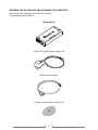
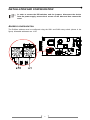
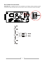
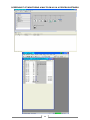
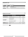
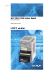
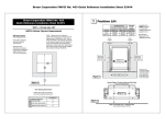
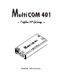
User Manual INTRODUCTION Thank you for choosing our product. The accessories described in this manual are of the highest quality, carefully designed and built in order to ensure excellent performance. This manual contains detailed instructions on how to install and use the product. It should be kept with care near the MultiCOM 401, so that it can be consulted for information on how to use and make the most of your device. IT SHOULD BE READ BEFORE YOU START WORKING ON THE DEVICE. SAFETY This part of the manual contains SAFETY precautions that must be followed scrupulously. The device has been designed for professional use and is therefore not suitable for use in the home. The device has been designed to operate only in closed environments. It should be installed in rooms where there are no inflammable liquids, gas or other harmful substances. Take care that no water or liquids and/or foreign bodies fall into the device. In the event of a fault and/or impaired operation of the device, do not attempt to repair it but contact the authorized service centre. The device must be used exclusively for the purpose for which it was designed. Any other use is to be considered improper and as such dangerous. The manufacturer declines all responsibility for damage caused by improper, wrong and unreasonable use. © No part of this manual may be reproduced without the prior written permission of the manufacturer. The manufacturer reserves the right to modify the product described in this manual at any time and without notice. 3 SUMMARY PRESENTATION ___________________________________________________ 5 DESCRIPTION __________________________________________________________ 5 OPENING THE PACKAGING AND CHECKING THE CONTENTS __________________________ 6 INSTALLATION AND CONFIGURATION ________________________________ 7 ADDRESS CONFIGURATION_________________________________________________ 7 BUS TERMINATION AND BIASING _____________________________________________ 8 JUMPER SETTINGS_______________________________________________________ 9 CONNECTION TO THE UPS _________________________________________________ 9 PROFIDRIVE MODE _______________________________________________ 10 CYCLIC COMMUNICATION (PROCESS DATA) ____________________________________ 10 PKW-PART___________________________________________________________ 11 PZD-PART ___________________________________________________________ 14 USER DEFINED PZD SLOTS _______________________________________________ 14 PERMANENT PZD CONFIGURATION _________________________________________ 15 LIST OF PARAMETERS ____________________________________________ 16 UPS PARAMETERS _____________________________________________________ 16 GATEWAY INTERNAL PARAMETERS __________________________________________ 19 PROFIDRIVE STANDARD PARAMETERS _______________________________________ 19 CONNECTORS PINOUT ____________________________________________ 21 DIAGNOSTIC LED ________________________________________________ 22 4 PRESENTATION DESCRIPTION MultiCOM 401 allows you to connect the UPS to a Profibus DP network. The device enables to integrate, in industrial enviroment, the management and monitoring of the UPS into a control system based on one of the most popular field bus designed especially for communication between automation control systems and distributed I/O. Baud rates from 9.6 kbit/s up to 12 Mbit/s are supported and automatically detected. The device also offers an RS-232 serial line through which the UPS can be monitored using the GPSER protocol (PRTK code: GPSER11201...). • A: RS-232 communication port • B: PROFIBUS connector • C: power supply connector • D: connector for connection to the UPS 5 OPENING THE PACKAGING AND CHECKING THE CONTENTS After opening the packaging, first check the contents. The packaging should contain: MultiCOM 401 12Vdc 0.5A external power supply unit DB9-RJ45 serial cable CD-Rom (User manual and GSD file) 6 INSTALLATION AND CONFIGURATION In order to access the DIP-switches and the jumpers, disconnect the device from the power supply, remove the 4 screws on the base and then remove the cover ADDRESS CONFIGURATION The Profibus address must be configured using the SW1 and SW2 rotary switch (shown in the figure). Allowable addresses are 1÷99. 7 BUS TERMINATION AND BIASING MultiCOM 401 is supplied with the bus termination and biasing resistors already mounted internally (R=100Ω). Dip-switch SW3 must be closed in order to insert these resistors (see figure). 8 JUMPER SETTINGS For proper working of the device, the jumper have to be set as shown in the figure below. = closed = open CONNECTION TO THE UPS Connect the “UPS SERIAL” port of the device to the serial port of the UPS using the cable supplied with the UPS. 9 PROFIDRIVE MODE The application can be drived in ProfiDrive standard compatible mode (ProfiDrive Mode). Driving mode is selected by using the appropriate GSD file: RPS_0B74.gsd. The gateway will accept all the configurations specified by Profidrive V2 (PPO1-PPO5). Using the ProfiDrive mode the standard ProfiDrive procedures can be used and it is possible to access to all application parameters in two possible ways: 1. Parameter area PKW: allow random access to any register in the range (1 – 799); 2. Process data area PZD: access automatically a predefined and configurable set of parameters. CYCLIC COMMUNICATION (PROCESS DATA) Cyclic communication data are exchanged with the Profibus DP master at every communication cycle. The exchanged data format and length are specified at the initialization by Profibus DP master using the Profibus DP configuration mechanism. The supported configuration are: Type Configuration bytes Process data layout Profidrive V2, PPO1 0xf3 0xf1 PKW + 2 words PZD Profidrive V2, PPO2 0xf3 0xf5 PKW + 6 words PZD Profidrive V2, PPO3 0xf1 2 words PZD Profidrive V2, PPO4 0xf5 6 words PZD Profidrive V2, PPO5 0xf3 0xf9 PKW + 10 words PZD The cyclic data consists of two parts, a parameter area (PKW) and a process data area (PZD). The layout of the process data is: PKW – 4 words PKE PZD - 2÷10 words IND PWE PZD 1 PZD 2 PZD 3 PZD 4 PZD 5 PZD 6 IND PWE PZD 1 PZD 2 IND PWE PZD 1 PZD 2 PZD 3 PZD 4 PZD 5 PZD 6 PZD 1 PZD 2 PZD 1 PZD 2 PZD 3 PZD 4 PZD 5 PZD 6 PZD 1 PZD 2 PZD 3 PZD 4 PZD 5 PZD 6 PZD 7 PZD 8 PZD 9 PZD 10 PZD 7 PZD 8 PZD 9 PZD 10 PPO1 PKE PPO2 PKE PPO3 PPO4 PPO5 PKE IND PWE The PKW part of the process data is used for asynchronous parameter access over process data. The PZD words can be programmed to hold a value of any available parameter of the word type. 10 PKW-PART The parameter part (PKW) is fixed to 4 words and can be used for reading and/or updating the parameters in the application one by one. Requests and responses use the predefined handshake procedure. The PKW is further divided into three parts: 1. PKE: Parameter ID (2 bytes); 2. IND: Sub-index (2 bytes), 2nd byte isn’t used and should be set to 0; 3. PWE: Parameter value (4 bytes). PKW PKE Parameter ID IND Sub-index PWE Parameter value Word 0 Word 1 Word 2 Word 3 b15 . . . . . . . . . . . . . . b0 b15 . . . . . . . . . . . . . . b0 b15 . . . . . . . . . . . . . . b0 b15 . . . . . . . . . . . . . . b0 PKE consists of three parts: 1. AKA: command/response identificator (4 bits); 2. SPM: toggle bit, not used (1 bit); 3. PNU: parameter number (11 bits). PKE b15 b14 b13 b12 AKA b11 b10 b9 b8 b7 b6 SPM b5 b4 b3 b2 b1 b0 PNU PNU parameters: 1÷799 are UPS PARAMETERS; 800÷899 are GATEWAY INTERNAL PARAMETERS; 900÷999 are PROFIDRIVE STANDARD PARAMETERS. AKA field meanings (master → slave) Value 0 1 2 3 4 5 6 7 8 9 Function No request Request parameter value Change parameter value (word) Change parameter value (long word) Request description element Change description element Request parameter value (array) Change parameter value (array word) Change parameter value (array long word)* Request number of array elements 11 Ack+ Ack- Note 0 1 1 2 3 3 4 4 5 6 7 7/8 7/8 7 7 7 7/8 7/8 7 not used not used not used AKA field meanings (slave → master) Value 0 1 2 3 4 5 6 7 8 Function No response Transfer parameter value (word) Transfer parameter value (long word) Transfer description element* Transfer parameter value (array word) Transfer parameter value (array long word)* Request number of array elements Request rejected, followed by fault code (in PWE part). Error values: 0 = Non-admissible parameter number 1 = Parameter value cannot be changed 2 = Upper or lower limit exceeded 3 = Erroneous sub-index 4 = No array 5 = Incorrect data type 7 = Descriptive element cannot be changed 9 = Descriptive data not available 11 = No parameter change rights 17 = Task cannot be executed due to operating status 22 = Parameter address impermissible 24 = Number of values not consistent 101 = communication error to the application No parameter change rights by PKW interface 12 EXAMPLES In the following examples, when you see: Index → you have to refer to LIST OF PARAMETERS chapter; xxxx → don’t care about the word’s value. Read word parameter (AKA=1): Output: Input: Word 0 Word 1 Word 2 Word 3 0x1000 + Index xxxx xxxx xxxx xxxx xxxx xxxx Value Read Input mains voltage V1 (Index 12 [0x000C] UPS PARAMETER): Output: 0x100C xxxx xxxx xxxx Read Output nominal power (Index 80 [0x0050] UPS PARAMETER): Output: 0x1050 xxxx xxxx xxxx Word 0 Word 1 Word 2 Word 3 0x2000 + Index xxxx xxxx Value xxxx xxxx xxxx xxxx Write word parameter (AKA=2): Output: Input: Write code 20 [0x0014] in Command code register (Index 113 [0x0071] UPS PARAMETER), in order to execute a battery test: Output: 0x2071 xxxx xxxx 0x0014 For further examples about this function, see PERMANENT PZD CONFIGURATION. Read array.word parameter (AKA=6): Output: Input: Word 0 Word 1 Word 2 Word 3 0x6000 + Index YY00 YY is sub-index of array xxxx xxxx xxxx xxxx xxxx Value Word 0 Word 1 Word 2 Word 3 0x7000 + Index YY00 YY is sub-index of array xxxx Value xxxx xxxx xxxx xxxx Write array.word parameter (AKA=7): Output: Input: For further examples about this function, see USER DEFINED PZD SLOTS. 13 PZD-PART MultiCOM 401 is provided with a default PZD input configuration: DEFAULT PZD INPUT CONFIGURATION PZD1 PZD2 PZD3 PZD4 PZD5 PZD6 PZD7 PZD8 PZD9 PZD10 DESCRIPTION UPS states (see the STATES table) UPS states (see the STATES table) Input mains voltage V1 Input mains voltage V2 Input mains voltage V3 Load phase L1 Load phase L2 Load phase L3 Remaining back-up time Remaining Battery Capacity Unit Flag Flag V V V % % % Minutes % 1 2 12 13 14 38 39 40 54 52 Index 0x0001 0x0002 0x000C 0x000D 0x000E 0x0026 0x0027 0x0028 0x0036 0x0034 In order to have different UPS parameters in PZD-part, the default configuration can be changed by user as described below. USER DEFINED PZD SLOTS For configurations the standard parameters 915 and 916 are used to define which values are transferred in these slots. Parameter 915 defines output and 916 input direction. Both parameters 915 and 916 are of array type and the subindex is used to reference the PZD slot (subindex 1 references PZD slot 1, subindex 2 references PZD slot 2, ... subindex 10 references PZD slot 10). Parameters of type word and byte can be selected (there is an implicit conversion byte-word). Not used PZD slots are marked with 0 in the parameters 915 and 916. EXAMPLES Set input PZD3 with Input mains voltage V1 (index 12 [0x000C] UPS PARAMETER): PKW Word 0 Word 1 Word 2 Word 3 Output: 0x7394 0x0300 xxxx 0x000C xxxx xxxx xxxx xxxx Input: Word 0 → Index used 0x394 (916dec) Word 1 → sub-index YY=03 (PZD3) Word 3 → Value = index of Input mains voltage V1 in UPS PARAMETER table Set input PZD10 with Battery voltage (index 48 [0x0030] UPS PARAMETER): Output: Input: Word 0 Word 1 Word 2 Word 3 0x7394 0x0A00 xxxx 0x0030 xxxx xxxx xxxx xxxx Word 0 → Index used 0x394 (916dec) Word 1 → sub-index YY=0A (PZD3) Word 3 → Value = index of Battery voltage in UPS PARAMETER table 14 PERMANENT PZD CONFIGURATION PZD configuration can be stored to non-volatile memory and automatically restored at the gateway power up. For this purpose the internal gateway parameter 802 is provided. By writing to this parameter the permanent storage of the PZD configuration is controlled. The possible values to be written to this parameter are: 0 → none 1 → clear non-volatile PZD setting 2 → store the current PZD setting to non-volatile memory 3 → restore the PZD settings from non-volatile memory The PZD setting saving is executed on the transition of the value of the parameter 802. To generate this transition firstly store 0 to this parameter and then the desired value. Ones that there are stored PZD settings in non-volatile memory, the function 3 (restore) is automatically executed at the gateway power up. In order to stop this auto-initialization the value 1 has to be written to parameter 802. EXAMPLES Store PZD setting to non-volatile memory: Output: Word 0 Word 1 Word 2 Word 3 0x2322 xxxx xxxx 0x0002 Must be 0 before. So write 2 and after 0 Word 0 → Index used 0x322 (802dec) Word 3 → Value = 2 (store the current PZD setting to non-volatile memory) Reset PZD setting to non-volatile memory: Output: Word 0 Word 1 Word 2 Word 3 0x2322 xxxx xxxx 0x0001 Must be 0 before. So write 1 and after 0 Word 0 → Index used 0x322 (802dec) Word 3 → Value = 1 (clear non-volatile PZD setting) 15 LIST OF PARAMETERS Parameters can be devided into three categories: 1. UPS parameters (from the range 1-799) 2. Gateway internal parameters (from the range 800-899) 3. Profidrive standard parameters (from the range 900-999) UPS PARAMETERS Index 1 2 Bit 0 1 2 3 4 5 6 7 8 9 10 11 12 13 14 15 0÷11 12 13 14 15 STATES UNIT Test in progress Flag Shutdown active Replace battery Battery charged Battery charging Bypass bad UPS communication lost Flag Flag Flag Flag Flag Flag On bypass Battery low Battery working UPS locked Output powered Flag Flag Flag Flag Flag Input Mains present Alarm temperature Alarm overload UPS failure Flag Flag Flag Flag 16 Index Data type MEASUREMENTS 1 2 3÷11 12 13 14 15 16 17 18 19÷21 22 23 24 25 26 27 28 29÷31 32 33 34 35 36 37 38 39 40 41÷43 44 45÷47 48 49÷50 51 52 53 54 55÷61 62 63 64 65÷72 Unsigned16 Unsigned16 UPS states (see the STATES table) UPS states (see the STATES table) Unsigned16 Unsigned16 Unsigned16 Unsigned16 Unsigned16 Unsigned16 Unsigned16 Input mains star voltage V1 Input mains star voltage V2 Input mains star voltage V3 Input current phase L1 Input current phase L2 Input current phase L3 Input frequency V V V 0.1*A 0.1*A 0.1*A 0.1*Hz Unsigned16 Unsigned16 Unsigned16 Unsigned16 Unsigned16 Unsigned16 Unsigned16 Bypass mains star voltage V1 Bypass mains star voltage V2 Bypass mains star voltage V3 Bypass frequency Output star voltage V1 Output star voltage V2 Output star voltage V3 V V V 0.1*Hz V V V Unsigned16 Unsigned16 Unsigned16 Unsigned16 Unsigned16 Unsigned16 Unsigned16 Unsigned16 Unsigned16 Output current phase L1 Output current phase L2 Output current phase L3 Output peak current phase L1 Output peak current phase L2 Output peak current phase L3 Load phase L1 Load phase L2 Load phase L3 0.1*A 0.1*A 0.1*A 0.1*A 0.1*A 0.1*A % % % Unsigned16 Output frequency 0.1*Hz Unsigned16 Battery voltage 0.1*V Unsigned16 Unsigned16 Battery current Remaining Battery Capacity 0.1*A % Unsigned16 Remaining back-up time Unsigned16 Unsigned16 Unsigned16 Internal UPS temperature Sensor 1 temperature Sensor 2 temperature 17 UNIT Flag Flag Minutes °C °C °C Index 73÷77 78 79 80 81÷83 84 85 86 87÷112 Data type Output nominal voltage (star) Output nominal frequency Output nominal power V 0.1*Hz 100*VA Unsigned16 Unsigned16 Unsigned16 Battery nominal capacity (battery expansion included) Battery benches Battery type Ah (1 or 2) Integer Data type 113 114 115 116 117 118÷120 Unsigned16 Unsigned16 Unsigned16 Unsigned16 Unsigned16 Unsigned16 (2) (3) UNIT Unsigned16 Unsigned16 Unsigned16 Index (1) NOMINAL DATA COMMANDS (1) Integer Seconds Minutes Command code Shutdown delay time Restore delay time Command result UNIT (2) Integer Refer to Command codes paragraph Command result = Command code if command is handled from the UPS Command result = Command code + 100 if command is NOT handled from the UPS Command result = 0 if Command code is wrong Index Data type 121 122 123 124 125 126 127 128 Unsigned16 Unsigned16 Unsigned16 Unsigned16 Unsigned16 Unsigned16 Unsigned16 Unsigned16 SPECIAL FLAGS (SENTR UPS)(3) Byte 1 of “s = xx..” code / Byte 2 of “s = ..xx” code Byte 1 of “c = xx..” code / Byte 2 of “c = ..xx” code Byte 1 of “b = xx..” code / Byte 2 of “b = ..xx” code Byte 1 of “r = xx..-..” code / Byte 2 of “r = ..xx-..” code Byte 3 of “r = ....-xx” code / Byte 1 of “i = xx..-..” code Byte 2 of “i = ..xx-..” code / Byte 3 of “i = ....-xx” code Byte 1 of “a = xx..-....” code / Byte 2 of “a = ..xx-....” code Byte 3 of “a = ....-xx..” code / Byte 4 of “a = ....-..xx” code In order to decode these registers, please refer to the UPS manual CODE 1 2 3 12 20 22 (0x0001) (0x0002) (0x0003) (0x000C) (0x0014) (0x0016) COMMAND Command shutdown Command shutdown and restore Cancel command codes 1, 2, 12 UPS on bypass Battery test Test panel 18 UNIT Flag Flag Flag Flag Flag Flag Flag Flag GATEWAY INTERNAL PARAMETERS These parameters are used in the ProfiDrive mode Index Data type R/W access Description 802 Unsigned8 Read-write Saving PZD setting to the gateway seeprom: 0 - nothing 1 - clear non-volatile PZD setting 2 - store the current PZD setting to non-volatile memory 3 - restore the PZD settings from non-volatile memory These parameters are used to identificate the gateway application type and application version. Index Data type R/W access Description 800 Unsigned16 Read-write Gateway application type 801 Unsigned16 Read only Gateway application version High byte - version Low byte - subversion PROFIDRIVE STANDARD PARAMETERS These parameters are defined by profibus standard. They are used in ProfiDrive mode. Index Data type Description 915 [8] Unsigned16 (Array) 916 [8] Unsigned16 (Array) 918 Unsigned8 PZD configuring, setpoint telegram Parameter is an array of 8 subindexes for defining output PZD slot content (0=PZD0; 1=PZD1,... 10=PZD10). PZD configuring, actual value telegram Parameter is an array of 8 subindexes for defining input PZD slot content (0=PZD0; 1=PZD1,... 10=PZD10). Gateway DP address 922 Unsigned16 964 [5] Unsigned16 (Array) 965 Unsigned16 971 Unsigned16 Telegram selection Value is 0 (telegram defined by 915,916 parameters) Device identification Array parameter with the following subindices meanings: Manufacturer code, device type, version, year, day+month Profile version and subversion (first and second byte) Saving parameters to the flash A change from 0 to 1 in this parameter value causes saving application parameter to flash (so actually two writings to 971 are needed for the request to save all parameters to flash). NOTE: Currently this parameter is not supported 19 SCREENSHOT OF MONITORING A MULTICOM 401 IN A PROFIBUS NETWORK 20 CONNECTORS PINOUT PROFIBUS CONNECTOR PIN # DESCRIPTION 1 NC 2 NC 3 RXTX+ 4 RTS 5 GND 6 +5Vdc 7 NC 8 RXTX- 9 NC SERIAL 2 PIN # DESCRIPTION 1 GND 2 GND 3 RXD 4 TXD 5 n.c. 6 n.c. 7 n.c. 8 n.c. 21 DIAGNOSTIC LED In the operational mode the meanings of LEDs are: LED Led RUN Led ERROR Color Description Green Blank Yellow Blank Regular working UPS communication error Profibus cable disconnected or gateway not in data-exchange Regular Profibus connection TECHNICAL DATA TABLE MULTICOM 401 POWER SUPPLY (1) ENVIRONMENT CONDITIONS PHYSICAL CHARACTERISTICS (1) Input voltage [Vdc] 12 Maximum input current [mA] 350 Operating temperature [°C] 0 ÷ +40 Storage temperature [°C] -5 ÷ +50 Relative humidity (in operation) [%] 80 (max) Relative humidity (in storage) [%] 90 (max) Dimensions H x L x D Weight [mm] [g] Polarity of the connector: 22 28 x 77 x 158 250 0MNU105NPB