1
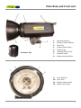
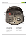
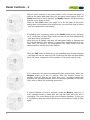
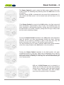
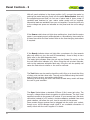
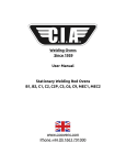
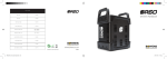
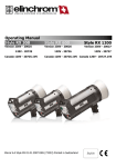
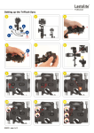
User Manual
Main Body and Front end
Protector Cap
1
2
3
4
5
6
7
8
Standard Reflector
Reflector Release Button
Slave Cell
Lighting Stand Clamp
Clamp Screw
Umbrella Clamp Screw
Umbrella Clamp
Reflector/Umbrella Slot
9
10
11
12
Inner Reflector
Flash Tube
Reflector Bayonet Slot
Safety Lamp Holder
3
Panel Controls
13
14
15
16
17
18
4
Mains Power Socket
Fuseholder & Fuses
Power On/Off
Modelling Lamp On
Modelling Lamp Full
Slave Cell On
19
20
21
22
23
Beeper/Sounder On
Flash Test Button
Ready-to-Fire Indicator
Flash/Modelling Power
Sync. Lead Socket
Fitting The Unit To a Light Stand
It is recommended that the F200/F400 be used with medium-weight lighting stands with standard
16mm male spigots. The stands must be stable when fitted with the unit and reflectors, umbrellas or
soft-boxes and when they are extended to full height. If the stand and unit fall over, severe damage to
the flash-unit is likely.
To release the Lighting Stand Clamp, turn the Tilt handle anticlockwise.
Swing the clamp to a new position then tighten. The Tilt handle can be
placed in any position by lifting it up against its spring, turning then
releasing.
Place the unit on the stand; loosen the Clamp Screw if required.
Retighten the screw so that it fits the unit securely to the stand's spigot.
The unit can now be tilted into any position. It is recommended that the
unit's handle be held with one hand while adjusting the tilt with the
other.
OPERATING PRECAUTIONS/SAFETY
The F200/400 units are designed for indoor use only and for connection to domestic 220-240VAC single
phase only. The unit must be operated with an adequate ground/earth, as normally found in three
connection mains plugs. For safety, a continuous ground connection to the camera is provided by the
low voltage sync. circuit and sync. cable.
Do not operate in damp conditions or with wet hands. High voltage is present inside, even when
disconnected from the mains. Do not open the unit; there are no user-serviceable parts inside.
Use only the recommended mains cable (supplied) and only the recommended modelling lamps.
Do not fire the flash faster or for more times within a period than recommended (refer to the unit's
specifications). Do not place inflammable material near the modelling lamp or flash-tube. Do not
enclose the unit so that the free-flow of air is compromised.
5
Reflector Fitting
If a Protector Cap is fitted, it must be removed before the unit is
switched on. Remove the cap by turning it anti-clockwise until the
cap bayonets can be lifted out of the reflector bayonet slots (the
Reflector Release Button may have to be slid back).
NEVER OPERATE THE LAMP OR THE FLASH WHILE THE
PROTECTOR CAP IS FITTED.
Damage to the unit could occur if the cap melts due to the heat from
the flash-tube or lamp.
Replace the Protector Cap when the unit is not in use.
Reflectors and other accessories (such as
Soft Boxes) can be fitted to the unit by
way of the three Reflector Bayonet Slots.
When fitting any accessories, do not
allow anything to touch the flash-tube.
The glass flash-tube can be damaged or
broken if it comes into contact with any
accessory.
It is preferable to fit the modelling lamp
after fitting the accessory, if it is
possible.
Line up the reflector bayonets over the
slots, as shown. If an umbrella reflector
is also going to be used, orientate the
reflector so that the oblong reflector slot
is at the bottom of the unit.
Engage the reflector bayonets and turn
the reflector until it stops. For security of
fitting, slide back the Reflector Release
Button and turn the reflector further.
At this point, the oblong reflector slot should be in line with the unit's umbrella clamp; if an umbrella is
going to be used, the umbrella shaft should pass through the reflector and into the slot of the umbrella
clamp. Note: When inserting the umbrella shaft, do not allow it to touch the flash-tube; damage to the
tube may occur. Always clamp the shaft into place using the Umbrella Clamp Screw (do not over-tighten
this screw; distortion damage to the shaft may occur).
To release the reflector, first remove the modelling lamp, if fitted. Turn the reflector anti-clockwise and,
at the same time, slide back the Reflector Release Button.
6
Modelling Lamp Replacement and Use
The F200/400 units are fitted with high temperature ES safety
lamp sockets which are designed to reduce the possibility of
injury due to electrical shock.
The following precautions are still required when fitting a lamp:
1.
2.
3.
4.
5.
6.
7.
8.
9.
10.
11.
12.
13.
14.
15.
16.
17.
The lamp rating must be a maximum of 275Watt 220-250V
Double-envelope, 230/250W, Halostar-type ES lamps are
recommended.
Standard 150W and 275W Photoflood ES lamps can also
be used.
Do not use single envelope, open QH lamps under any
circumstances.
Turn the unit off before fitting a lamp.
Turn the unit off and allow the lamp to cool before
replacing it.
Keep fingers away from the socket or the lamp thread
when fitting the lamp.
Avoid touching the flash-tube with the lamp. Note that
the flash-tube is not user-replaceable; flash-tube
replacement must be carried out by qualified engineers
only.
It may be necessary to replace the unit's fuse if a lamp
has broken; refer to fuse replacement instructions.
Most lamps are fragile and can easily break. Take care
when fitting a lamp.
The ES screw socket may require the lamp to be fully
screwed down in order to make contact. If a new lamp
fails to light, check that it is fully screwed down.
Take care not to damage the lamp when fitting
reflectors and accessories.
Lamp filaments are fragile, particularly when hot. Avoid
moving or jarring the unit when the lamp is on.
Anything placed in front of the lamp must be fireresistant. Soft-box material must be suitable for the
purpose.
The lamp envelope and the surrounding metal will
become hot during use.
Avoid fitting accessories that restrict the flow of air
around the lamp and flash-tube.
The unit is fitted with a comprehensive system of thermal
safety cut-outs. These cut-outs will shut the flash circuit
down in the event of overheating. The overheat condition
will be indicated by the Ready light being extinguished even
when the Power switch is illuminated. The lamp will still be
on if the lamp Full switch is on. If the overheat condition is
indicated, switch the unit off and leave it for 30 minutes. If
the overheat condition persists, refer the unit to a qualified
engineer to be repaired.
7
Panel Controls - 1
With all panel switches in the down position (off), connect the mains by
pushing the mains lead plug firmly into the panel mains socket. Push the
Power switch up to the on position; the Ready indicator will light showing
that the unit is ready to flash.
Press the flash Test button (see page 10) to fire the flash (if the power
switch does not illuminate when switched on, the unit's fuse may be blown
- see fuse replacement instructions).
If modelling light is required, switch up the Model switch to turn the lamp
on (if a lamp has not been fitted, switch off the unit and fit a suitable lamp
- see lamp fitting instructions).
When the unit is flashed, the lamp will extinguish briefly to indicate that
the unit has flashed - this function is useful when multiple flash units are
used. With this function, the photographer can easily check from the
camera position that all units have flashed.
When the Full switch is switched up, the modelling lamp function changes
- the lamp will stay on when the unit is fired and the lamp will also always
be at full power, irrespective of the position of the power control knob.
If it is required to fire the unit automatically from another flash, switch the
Remote switch up to the on position. With this function turned on,
multiple units will flash at the same time; sync. connecting cables are
therefore not required between units. For optimum operation of the Slave
Cells, refer to Slave Cell operating instructions.
If sound indication of firing is required, switch the Beeper switch on. A
brief, repeated sound is made after the unit has fired while the unit is
recharging. The sound stops at the point of Ready indication. In this way
it is possible to hear the time at which one or more units are ready to flash
again.
8
Panel Controls - 2
The Power Control is used to select the flash power output of the unit;
it also controls the modelling lamp dimming when the Full switch is in the
off position.
Minimum power, 1/32, is selected with the control fully anticlockwise. In
this position the flash power is at the lowest level and the lamp is at its
dimmest.
If the Power Control is turned to the 1/16 position, the flash output will
have increased by approximately 1stop of light. The modelling lamp will
have increased in approximate proportion (actual lamp level increase will
be determined by a number of factors, among them the type of lamp used
and the mains operating voltage).
Turning the Power Control clockwise to the 1/8 position will increase the
flash by another one stop (approximately double the light). Mid-way
positions can be used for increases in light of less than one stop; the
control has small click indents to aid fractional power selection.
The lamp dimming can be used to indicate relative flash power between
units when using multiple units (Full switch in the off position).
Turning the Power Control clockwise to the 1/4 position will again
increase the power by one stop. Power can be decreased at any time by
turning the control anticlockwise. When power is decreased, the unit will
auto power-dump by flashing. In this way, the unit will automatically get
rid of excess power.
1/2 and 1 (Full) Power can be selected in a
similar way. At full power the flash and modelling
output are at maximum. Note that small changes
in flash colour temperature and flash duration
occur when the power control is changed.
9
Panel Controls - 3
With all panel switches in the down position (off), connect the mains by
pushing the mains lead plug firmly into the panel Mains Socket. Use only
the supplied approved lead, do not use a mains lead of lower power. A
moulded lead matched to your mains outlet socket will be supplied.
Alternative leads are available from your unit supplier. Connect the unit only
to the voltage and power as indicated on the panel and the unit's ratings
label.
If the Power switch does not light when switched on, check that the mains
power is connected properly and switched on. Alternatively, there could be
a blown fuse within the fuse socket. Refer to the fuse changing instructions
if required.
If the Ready indicator does not light after a maximum of a few seconds
after unit switch-on, turn the unit off immediately - there is likely to be a
fault; refer to the fault diagnosis chart.
The ready light indicates when the unit can be flashed. Do not try to fire
the unit before this indicator is lit. When firing the unit at short intervals,
refer to the maximum advisable flash rate; firing the unit too quickly can
cause the flash tube to misfire or the unit to overheat.
The Test Button can be used to check the unit's firing or to check the firing
of other units via their slave cells. The unit can be flashed using the button
even if there is a sync. connection cable fitted.
Switching on and firing the unit a few times at least every month will keep
the unit in good condition.
The Sync Socket takes a standard 6.35mm (1/4in) mono jack plug. The
low sync. voltage allows direct connection to most cameras. The sync. lead
supplied connects to the camera's PC socket. If your camera has a hot-shoe
connection instead of a PC socket, a hot-shoe adapter, available from most
photo retailers, will allow the sync. lead to connect to the camera.
Some remote trigger systems can be plugged into the unit's sync. socket,
though sync. circuit damage could result if an unsuitable connection is
made; check with the unit's supplier if in doubt.
10
Fuse Replacement
The F200/400 fuse protects the unit from further damage after a component malfunction. In many
cases, the cause of a fuse blowing may simply be a modelling lamp failure. Some lamps temporarily
short-circuit when they fail causing the unit's fuse to blow; there may then be no other malfunction in
the unit. Once the fuse and lamp has been replaced, the unit can be ready to use once again.
If the fuse has blown, both the illuminated Power on/off switch and the Ready indicator will not light
when power is applied to the unit.
Note: It is important to replace the fuse only with one of the same rating. For both units, the fuse type
is as follows: 6Amp (or 6.3Amp), 20mm, 220-250V, Antisurge, Ceramic.
The fuse designation is sometimes written as: 6.3A(T) or 6.3AL
For convenience, all flash units are provided with a spare fuse built into the fuse-holder.
The following procedure must be taken to replace the fuse:
The fuse-holder is accessed by first removing
the mains plug from the unit. The fuse-holder
can then be gently levered out to reveal the
main fuse (A) and the spare fuse (B).
Replace the fuse-holder into the mains socket
and plug the mains plug back again. If the
fuse-holder has been incorrectly replaced, the
mains plug will not fit.
Unhook the main fuse and discard. Push out
the spare fuse from the holder and place it into
the original position of the main fuse.
When the power is switched on, the Power
switch will illuminate and the unit will come to
Ready. If this does not happen, there may be
another fault, possibly internal to the unit. The
unit then may require repairing by a qualified
technician.
DO NOT OPEN THE UNIT UNDER ANY CIRCUMSTANCES
OR ATTEMPT A REPAIR YOURSELF
11
Stored Energy
Guide Number (m/100iso)
Recycling Time (100%)
Flash Duration
Lastolite
Lastolite
Lumen8 F200
Lumen8 F400
200 w/s
400 w/s
42
60
0.3 ~ 0.9 sec
0.4 ~ 1.6 sec
1/700 ~ 1/1700 sec
1/700 ~ 1/1700 sec
Flash Power
Full ~ 1/32nd
Full ~ 1/32nd
Power Control (stepped rotary dial)
1/10th F’Stops
1/10th F’Stops
Body Construction
Unit Colour
User Replaceable Flash Tube
Modelling Lamp
Modelling Lamp Modes
Auto Dump
Colour Temperature
Metal casing with
Metal casing with
plastic control panel
plastic control panel
All Black
All Black
No
No
250w
250w
Full, Prop, Off
Full, Prop, Off
Yes
Yes
5300 ~ 5600k
5300 ~ 5600k
Slave Cell
Yes (10 metres)
Yes (10 metres)
Triggering Methods
Sync, Test, Slave
Sync, Test, Slave
Rocker Switch
Rocker Switch
Main Operating Controls
Sync Voltage
Voltage Stabilisation
Fan Cooled
Thermal Cut Off
4v DC
4v DC
+/- 1%
+/- 1%
No (not required)
No (not required)
Yes (x2)
Yes (x2)
Ready Light
Yes
Yes
Audible Recharge Confirmation
Yes
Yes
170 ~ 240v
170 ~ 240v
50 ~ 60Hz
50 ~ 60Hz
Operating Voltage
Umbrella Fitting
8mm
8mm
Fuse rating
6 amp
6 amp
Spare Fuse Supplied
Yes
Yes
EM Noise Supression
Yes
Yes
410 x 182 x 210mm
410 x 182 x 210mm
Length x Width x Height (mm)
Weight
Mounting System
www.lastolite.com
2.3kg
2.5kg
‘S’ Type compatible
‘S’ Type compatible