1
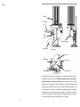
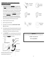
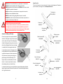
Promatic International Ltd.
Station Works,
Hooton,
South Wirral
CH66 7NF,
United Kingdom.
Tel: +44 (0) 151 327 2220 (General)
+44 (0) 1407 860800 (Sales)
Fax: +44 (0) 151 3277075
E-mail [email protected]
Website: www.promatic.co.uk
Promatic Inc.
7803 West Hwy 116
Gower
MO 64454
USA.
Toll Free: 888.767.2529
Fax: 816.539.0257
E-mail: [email protected]
Website: www.promatic.biz
Ranger Chondel Version 2 August 2014
24
Operating Instructions
Ranger Chondel - Clay target launcher
WARNING
Clay target launchers can be
dangerous and must be treated
with great care at all times to
avoid accidents.
Never place any bodily part into
the path of any mechanical piece
whilst the machine is in motion or
likely to be so.
Specifications:
300 target Carousel.
Weight: 80 kg / 176 lbs
Length: 800mm / 31½“
Width: 410mm / 16 “
Height: 1095mm / 43”
You must treat a clay target launcher with the same caution that you
would treat a loaded gun. Assume at all times that a clay target launcher is
armed and loaded and treat it accordingly
This document must be read in full before attempting to operate the machine
Preface:
Every effort has been made to ensure that the information contained within this manual is complete, accurate and up-to-date. Promatic International assumes no responsibility for errors beyond its control.
Conventions used within this manual:
Trap: Your Ranger Chondel Clay target launcher, commonly known as a clay trap and
may be referred to in this manual as “The trap” or “The machine”
Warnings & Cautions:
Warning: This section contains instructions which, if ignored or carried
out incorrectly, may result in risk of personal injury.
Caution: This section contains instructions which, if ignored or carried out
incorrectly, may result in malfunction or damage to the equipment or
consumables.
Note: This section contains additional information which the user may
find useful, but is not essential to the operation of the product.
12v DC Power Source:
This trap is designed to be powered from a 12v
DC battery, it MUST NOT BE DIRECTLY CONNECTED TO MAINS AC POWER
Battery: Where a trap is connected to any other
suitable power source i.e. a Transformer - the relevant sections of instructions should still be observed, i.e. “Disconnect the battery” and applied
to this or any other power source.
EYE PROTECTION MUST BE WORN WHEN WORKING ON OR AROUND A CLAY TARGET LAUNCHER
AS SMALL SHARP PIECES OF CLAY MAY BE EJECTED DURING NORMAL USE.
2
23
Understanding your new trap: (Guard has been removed for clarity in the side view)
NOTES:
Carousel
Throwing
Arm
Roller
Switch
Motor & Gearbox
Casting Plate
Spring Finger
Top Plate
Knife edges
Rear Pusher
Let Down Ramp
Thank you for purchasing your new Promatic Trap. If maintained properly it will give
many years of trouble free service. Before proceeding any further, checks need to
be made to ensure your Trap is in a safe state. When making these checks, stay well
away from the Trap. As supplied, the Trap should be in Transit mode. Before proceeding any further check that this is the case. Transit mode is described on page 4. If this
is not the case, the trap may be in safe mode as described on page 5. If the Trap does
not appear to be in any of these two positions assume it is unsafe, even if the power
source is dis-connected. Do not approach the Trap. Assume it could fire at any time.
Follow the procedure on page 5 and ensure the Trap is disarmed.
22
3
Transit Mode Procedure - This is recommended for machine transportation.
Warning: Stand at rear of machine only
a)
Disarm the machine by flicking the ARM/DISARM switch upwards towards
the DISARM position and immediately releasing (long enough for the trap to
fire, but not giving the machine a chance to rearm). The throwing arm should
be pointing towards the front of the machine. The Gearbox block (A rectangular block attached to the gearbox shaft) should be in a position pointing towards the front of the machine. Push the ARM/DISARM switch momentarily
in direction of DISARM/NUDGE just enough to allow the block past its forward pointing position. The gearbox block will now be pointing slightly up
with the drive pin just above the gearbox shaft. If the block has gone too far,
follow this procedure again until the desired position is achieved.
b)
Disconnect the power source from the machine.
c)
Adjust the spring to reduce the tension.
d)
The throwing arm can be pushed slowly, USING THE PALM OF THE HAND
ONLY, around clockwise .
e)
As the throwing arm gets to the firing position (pointing directly to the back of
the machine) the spring will take over, moving the arm onto the drive bolt on
the Gearbox block. This will stop the arm and prevent it from firing.
f)
This is TRANSIT MODE. The arm is now locked between the drive bolt and the
one-way bearing within the trap, it cannot move or release again until power
is applied and the ARM/DISARM switch operated.
Gearbox block
Command cable
E03V/CCCH
5 pin relay
E09V/5PIN
5 amp fuse
E10V/F05A
40 amp fuse
E10V/F40A
Toggle switch
E11V/7430
Main shaft spacer
D04N/SP18
Spare Parts List:
For parts not listed please call Promatic or you local dealer / service agent or visit
UK & ROW — www.promatic.co.uk
USA — www.promatic.biz
Drive pin
View from right of Trap
Mainshaft pin
Direction of rotation
of Throwing arm
Gearbox shaft
Mainshaft pin locked against Drive pin. Note that
some detail has been removed for clarity.
4
21
Never approach the machine from the front or sides, Do not assume
the trap is safe even without electrical power it may still be armed
and can fire without power being applied.
Motor & Gearbox
M01V/63918
Read and understand this manual. It contains important instructions
for the safe operation of the machine. Under no circumstances must
an inexperienced operator be allowed to work with the machine.
Main bearing set
B00V/SET1
Connecting the battery:
Rear pusher roller
D04N/RN25
Ensure you are behind the machine, the ARM/DISARM switch is in the OFF position
and it is otherwise safe to proceed. Connect the red cable to the Red (+) terminal and
the black cable to the Black (-) Terminal. Ensure the terminal fasteners are tight and
the charger has been removed.
Disarming the machine (Safe mode).
1.
Roller switch
RN6/7200
Spring roller
RN6/2630
2.
To disarm the machine push the ARM/DISARM switch upwards to the DISARM
position and immediately release (long enough for the trap to fire, but not giving the machine a chance to rearm). The throwing arm should be pointing towards the front of the machine.
Turn the ON/OFF or
switch (if fitted) to the OFF or
position and disconnect the battery.
Positioning the machine
1.
Main spring
S01Z/SHTR
Backrail
RCH/3440
2.
3.
Clay Target Launchers must be situated on firm level ground in a position that
will allow unrestricted access to rear of machine.
There must be no obstructions to the path of the throwing arm.
Ensure that the power supply can be easily disconnected and cables cannot become tangled in any part of the mechanism.
Firing the machine (Ensure the range is clear at the front of the trap.)
1.
Teal finger
RN6/3500
Rear pusher spring
S02Z/037D6
20
2.
3.
Turn the ON/OFF or
switch (if fitted) to the ON or
position and set the
ARM/DISARM switch to the ARM/LOAD position. The machine will move automatically and arm itself ready to launch a loaded clay.
Press the FIRE button on the command cable to throw a clay.
The machine will fire every time the FIRE button is pressed and will automatically rearm itself, until disarmed and switched off. When switched off, disconnect
the power source.
5
ALWAYS disarm the machine before any, adjustment or maintenance.
ALWAYS disconnect the battery after making the Trap safe.
ALWAYS approach the Trap from the rear, NEVER from the front or sides
and ONLY if the machine is disarmed .
NEVER allow children or untrained persons to approach the machine.
NEVER move an armed/loaded machine.
REMOVE the main throwing spring before transport in a vehicle.
BE AWARE of the fall zone of both broken and unbroken clays and that a
change in wind direction will affect this.
WARNING BEFORE ANY MACHINE ADJUSTMENTS
Part of this procedure requires you to work very close to the trap - before
proceeding be sure you understand and have practised the procedure for
putting the trap into safe mode (this can be found on page 5 of this manual)
and fully understand when the trap is safe and when it is not.
Spare Parts List:
This is a list of spares, but is not exhaustive. For parts not listed please call Promatic or
you local dealer / service agent or visit www.promatic.co.uk
Throwing arm
RCH/2100/13
Friction strip
RN6/2200
Clay sweeper
A28S/PAJH
Adjustment: Setting up knife edges
Place a clay target on the top plate and slide it
under the knife edges. Using a 10mm spanner/
wrench, adjust the height of the leading edge
of both knife edges by moving the nuts on each
side of the knife edge. When the correct height
in reached, lock the nuts against each other.
It is desirable to have the knife edges as close
to the shoulder of the clay as possible but leaving sufficient clearance to allow for deviation in
clay thicknesses. Spinning the clay will give a
good average of the shoulder height. This
height is factory set and should work ‘out of
the box’. It is worth a quick check to ensure
these settings match your brand of clays.
It is important that the clay is not pinched but can move freely beneath the knife
edges. A gap of around 0.5mm usually works well. If the shoulder height deviates,
set to a greater clearance.
Deflector holder
CH/3650
Deflector plate (LGE)
A28S/AXMR
Deflector plate (SML)
A28S/BWMT
Cone spring
E12V/BENCS
Outer knife edges
RN6/3150
Inner knife edge
RN6/3250
Outer knife edge block
RN6/3200
Inner knife edge block
RN6/3300
Let down ramp
FN6/3400
6
19
ALWAYS disarm the machine before carrying out loading, adjustment or
maintenance.
d)
e)
Check the Throwing arm timing relationship. If this relationship is incorrect the
trap will definitely break clays when throwing. The timing can be adjusted to
the diagram found on Page 10 in this manual.
Finally, after all the above has been tried, as a check for inferior clays, slacken
the main spring. Fire a few clays with the spring slack. This significantly reduces
the stresses put into the clay during the firing process. If the clays break, this is
a good indication that the clays themselves are sub-standard.
It is also important that the knife
edges have the correct clearance
around the diameter of the clay
and that they support the skirt of
the clay above the knife edges for
its entire travel along them.
To set this, slacken the nuts holding the inner knife edge. Hold the
clay against the inner two carousel
bars and gently tap the knife edge
until there is approx. 1mm clearance between the dome of the clay
and the knife edge. Tighten the
fixing bolts.
1mm
1mm
0.5mm
1mm
0.5mm
1mm
Now hold the clay against the two
outer carousel bars. Again gently
tap the outer knife edge until there
is approx. 1mm clearance between
the dome of the clay and the knife
edge. Tighten the fixing bolts. Refer Carousel bars
to the illustrations.
The procedures for adjusting the height of the knife edges and the clearance to the
dome of the clay are best performed together. Care taken at this stage will result in
fewer ‘no birds’ and many hours of trouble free use.
Problems usually revolve around the clay pigeons themselves or the variation in their sizes between the different manufacturers. Poor maintenance
and cleaning or physical damage caused during transportation of the machine are the other normal causes. Items that should be treated with great
care include the throwing arm, casting plate and electrical box.
18
7
Adjustment: Setting Elevation Angle
3. The trap breaks clays
Trajectory of clays can be set from Rabbit to near Teal mode. Loosen Elevation nut as
shown, elevate to desired angle and firmly re-tighten nut.
Check the loading procedure.
a)
Check that the clays are intact and free of chips and cracks before loading into
the carousel. Discard damaged clays.
b)
With the trap switched off, rotate the carousel by hand until a clay feeds onto
the casting plate. Remove this clay and check for chips and cracks. If found, remove the entire carousel and find a clay that has the thickest shoulder. This clay
should slide easily beneath both knife edges as per the setup instructions on
Page 6. If this is not the case, reset the knife edges using the same procedure.
c)
If the clay breaks on contact with the casting plate, check that the soft fall plate
offers a degree of damping for the clay as it drops. By design, the soft fall plate
should sit very slightly above the casting plate, and should assume a slightly
domed shape. Check this and make adjustments if necessary. Note that the gap
between it the soft fall plate and the casting plate is very small. If after adjustment the clays are still breaking it is likely that the clay is too soft and unsuitable for use.
d)
Check that there are no tight spots in any of the carousel pockets. Test this by
taking a handful of clays and slide them up and down the length of the carousel
pockets. If they are tight against any of the rails, reshape them to allow free
movement. This can be made easier by using a lever such as the handle of a
spanner.
Elevation Nut
Be aware that when making Elevation and Tilt adjustments, the Trap is
likely to move suddenly. Support the weight of the machine from the top
of the carousel when adjusting these settings.
Adjustment: Setting the Tilt Angle
The Trap can be tilted both to the left and right. Loosen Tilt adjustment bolts as shown.
The desired tilt can be achieved by slackening one or other of the bolts and then tightening the other firmly onto the Trap base.
If the clay is now dropping correctly onto the casting plate prior to firing, but the trap
fires a broken clay, then the fault probably lies in the throwing cycle.
Check the throwing cycle.
a)
Check the throwing arm for straightness, for pieces missing from the rubber/
plastic friction strip or any other physical damage to the arm. If the arm cannot
be straightened then it should be replaced. A new friction strip can be fitted to
an old arm if necessary .
Tilt adjustment bolt
b)
Check for damage to the casting plate especially the front edge of the plate.
Check for flatness, ensure that no screw heads protrude and that there are no
other obstructions to the clay’s path. Correct faults as necessary.
c)
Check that the screw holding the throwing arm to the clamp block is tightened correctly.
Tilt adjustment bolt
8
17
ALWAYS disarm the machine before carrying out loading, adjustment or
maintenance.
ALWAYS disarm the machine before carrying out loading, adjustment or
maintenance.
Mechanical Troubleshooting.
Adjustment: Spring Tension
1. Carousel does not rotate
Spring adjustment is always easier if the spring roller on the main shaft is at its rearmost position, this relieves the spring of a large proportion of it’s tension making adjustment much easier as well as reducing wear on the spring adjustment mechanism.
To achieve this, first perform the Safe Mode Procedure (see page 5) to put the machine into safe mode and then nudge forward until the throwing arm projects forward
from the front of the machine. At this point stop nudging and disconnect the battery.
Loosen the spring adjustment nut.
Check.
a)
The carousel pusher arm is not jammed.
b)
The pusher return spring is broken or missing. Replace if necessary.
c)
With the pusher arm withdrawn, the carousel should be free to rotate with a
small amount of friction. This is adjusted by tensioning the lock nut against the
blue plastic sleeve at the centre of the carousel.
d)
The carousel timing is correct ie. When the gearbox crank and connecting rod
are in line at maximum extension, the rollers on the bottom of the carousel
pusher arm are 1mm clear of the top plate at maximum travel. Adjustment can
be made by slackening the clamp on the rear pusher shaft and resetting the
rear pusher as above. Retighten the clamp before operating the trap.
To increase the spring tension, move the Lock nut towards the coil spring and then
tighten the Adjustment nut behind it.
To reduce the spring tension, move the Adjustment nut away from the spring coil and
tighten the lock nut behind it.
2. Sub standard targets are thrown
a)
If the clay flicks up in the air it is likely that the arm is bent down or the casting
plate is bent up. This has the effect of pinching the clay causing irregular flight.
Straighten the arm and/or reset the casting plate. If this is not possible, replace
them as necessary.
b)
The clay has no distance — the throwing arm is probably bent upwards allowing
the clay to pass beneath the arm. This loss of contact will significantly reduce
the thrown distance and can also lead to broken clays. Straighten or replace the
arm.
c)
The direction of the clays are inconsistent. This can be caused by a warped arm
not holding the clay against the casting plate. In this case, straighten the arm
and reset the height of the casting plate to give a gap between the friction strip
on the arm and the shoulder of the clay of between 1mm and 1.5mm. Sometimes the thickness of the clay shoulder varies. Resetting the height of the
casting plate in the same way as above will restore clay target consistency.
16
Adjustment nut
Lock nut
Important: leave 30mm (1 3/16”) thread length between lock nut and
spring coil. Increasing spring tension up to full length of thread will
seriously detriment the performance of the machine and will cause
spring damage or failure.
9
Adjustment: Throwing arm timing
A.
Disarm the machine by flicking the ARM/DISARM switch upwards towards the
DISARM position and immediately releasing (long enough for the trap to fire,
but not giving the machine a chance to rearm). The gearbox block will now be
pointing towards the front of the machine.
B.
Flick the ARM/DISARM switch upwards towards the DISARM position repeatedly until the gearbox block points towards the back of the machine put does not
contact the throwing arm. This reduces the spring tension.
C.
Note the position of the opening in the hook (down) and remove the spring.
D.
With the spring removed, rotate the throwing arm until the mainshaft crank is
pointing towards the front of the machine with the upper face perpendicular
(90°) to the front edge of the mainframe. See Diagram 1 below.
E.
On the other side of the machine, loosen the throwing arm clamp block bolt
until the throwing arm will move around the mainshaft. Rotate the throwing
arm anti-clockwise (this is so the mainshaft is held by the one-way bearing and
doesn’t move) until the throwing arm points roughly towards the back of the
machine and upper edge of the throwing arm clamp block is parallel with the
top edge of the frame immediately behind it. See Diagram 2 below.
F.
G.
Making sure both the mainshaft crank and the throwing arm are in the positions
described, firmly tighten the throwing arm clamp block bolt. The arm timing is
now complete.
Replace the spring paying attention to the orientation of the hook. See page 4.
Diagram 1.
4.
Machine cocks, but will not fire on command cable button.
(a)
Either the connections, cable or command push button are faulty. Disconnect
the Hirschman connector on the command cable. At the Hirschman connector on the trap, short out pins 2 & 3.
If the trap does not fire then there is a broken wire in the cable or a bad connection in the hirschmann connector or in the control box.
(b)
If the trap does fire then reconnect the command cable, remove the cover on the
push button box and short across the two spade connectors. If the trap fires then the push button is faulty. If the trap does not fire - then there is a broken wire
in the command cable or a bad connection in the hirschmann connector.
5.
Trap fires by itself!
(a)
Disconnect the command cable and switch the trap back on. If the trap cocks normally - then the command cable is damaged or shorted out. Alternatively, the push
button switch is stuck in or faulty.
(b)
If the trap continues to fire - then check the arm to crank timing relationship as
described on page 10 in this manual. If the above relationship is correct then,
after having put the trap into the disarmed/safe position, move the roller limit
switch up along the slotted bracket to its maximum. If the machine now cocks
normally - then move the limit switch back to within 5mm of its original position. If
the trap now fires by itself again then move the switch to 10mm of its original position and so on until the trap cocks normally under all conditions.
(c)
If the machine still fires by itself - check if the relay contacts have stuck together,
and if so replace. If the relay operates correctly, but the trap still fires by itself, then
the roller limit switch is faulty and should be replaced.
Diagram 2.
Parallel
Clamp block bolt
10
ALWAYS disarm the machine before any loading, adjustment or maintenance.
ALWAYS load clays from rear and ONLY if the machine is disarmed and safe.
NEVER approach the machine from the front or sides. ALWAYS from the rear.
NEVER allow children or untrained persons to approach or touch the machine.
NEVER move an armed/loaded machine.
ALWAYS disarm and disconnect battery.
REMOVE the main throwing spring before transport in a vehicle.
BE AWARE of the fall zone of both broken and unbroken clays and that a change in
wind direction will affect this.
15
ALWAYS disarm the machine before carrying out loading, adjustment or
maintenance.
ALWAYS disarm the machine before carrying out loading, adjustment or
maintenance.
Electrical Troubleshooting.
1.
Machine does not cock (i.e. come to the loaded position).
(a) Check the battery is charged and that the connections are clean and tight.
(b) Check the toggle switch is in the down (ON) position.
(c)
2.
Check the Throwing arm is clear of the Roller switch under the Casting plate. If
not, then press toggle switch up to nudge the Arm around until it is clear, then
switch it back down to the ON position. During this procedure it is possible the
machine will fire.
Adjustment: Spring Finger
Loosen the nut holding the Spring
finger. Position the Spring finger
with the spring pointing directly
towards the lower bolt holding the
back rail. (See illustration).
Align spring with bolt
Machine still does not cock.
(a)
Check all connections are tight including those inside the electrical box.
Check for broken wires and damaged connections.
(b)
If there are no broken connections (battery connected, all switches on) press
toggle up to “NUDGE”, listen and watch for the 12v relay operation in the control
box.
(c)
If the relay operates but the motor does not turn - short across the 2 large contacts on the relay with a screw driver or piece of wire. (These are the two terminals with red wires connected to them). If the motor does not turn - then the
motor is suspect. If the motor does turn - then the relay is faulty. Contacts may
be dirty or worn out.
(d)
If the relay does not operate – check the fuse has not blown. Replace fuse if
it has blown and try again.
(e)
If the motor does not turn - then short the brown wire to the yellow/green wire
on the back of the toggle switch with the switch in the “NUDGE” position. If the
relay operates and the motor turns then the toggle switch is faulty. If the relay
still does not operate, then it’s the relay that is faulty.
3.
Machine runs in “NUDGE” position, but not in “ON” position.
If the arm is clear of the Roller Switch then the Roller Switch may be faulty. Check
that the roller arm is not seized. If so, strip, clean and re-assemble. Otherwise replace the Roller Switch.
14
Adjustment: Roller Switch
Loosen both wing nuts and
slide the roller switch so that
the slot revealed measures
10mm. (See illustration). The
gap is measured between the
end of the slot and the body of
the wing nut.
11
ALWAYS disarm the machine before carrying out loading, adjustment or
maintenance.
Adjustment: Teal Fingers
The Trap has 3 teal fingers fitted to
the inside of the outer guard plate.
The Teal finger nearest to the throwing arm should be positioned so it is
resting on the casting plate pointing
towards the centre of the spring finger (approx). The other 2 should be
aligned so that the tips of each are in
line with the inside edge of the
backrail.
Teal fingers
This diagram shows the adjustment of
the nuts and the affect it has on the deflector plate. Note that the clay should
be held mid way across the dome. If not,
adjust the spring finger until it is.
Note that some parts have been removed from the illustration for clarity.
Adjustment: Switching from Standards to Rabbits (USA models only)
Backrail
Adjustment: Deflector Plate
The deflector plate is adjusted using
the 3 nuts as shown in the illustration to the right. The outer 2 nuts
are used for Standard clays. The centre nut is used for Rabbit clays.
When setting the deflector plate for
Standard clays, adjust the 2 nuts
until the clay is just held against the
casting plate with no gaps. The clay
should be held across the centre of
the dome.
Ensure that the machine is in the DISARMED/SAFE position and that the battery is disconnected.
Remove the outer guard by un-doing the 19mm nylock nut and the two 8mm wing nuts.
Remove the standard throwing arm and replace with the Rabbit throwing arm. The arm
is attached to its mounting block with one bolt, a 19mm or 3/4” spanner will be required. Do not move the mounting block position on the main shaft or machine timing
will be lost and have to be reset. After fitting the arm, refit the outer guard.
The clay deflector will now need to be adjusted. This is done by un-winding the three
lower horizontal 10mm nylock nuts on the side of the outer guard.. By loosening these
three nuts the spring loaded deflector is pushed closer to the clay. This is necessary as
the thinner Rabbit clays would fall out the bottom of the machine if the deflector was
left set for Standard clays. Adjust the three nuts enough so that when a Rabbit clay is
loaded the deflector supports it and holds the clay against the throwing plate.
If the clay is to be loaded the upside down, spacers (supplied) need to be fitted beneath the knife edge blocks and a second carousel washer (supplied) fitted onto the
carousel shaft. The knife edges will need to be reset, see page 4.
When setting up for Rabbit clays,
Unscrew the 2 outer nuts, then adjust the centre nut until the Rabbit clay is just held in
the same way. This is usually done by unscrewing the nut allowing the springs to extend the deflector plate further towards the casting plate. Once set the centre nut will
probably never need re-adjusting. Move between Rabbit and Standard clays simply by
adjusting the 2 outer nuts. (Refer to ‘Switching from Standards to Rabbits on Page 13).
12
Prepare the machine for operation and fill with Rabbit targets before reconnecting the
battery. Take care to ensure they are loaded correctly!
13