1
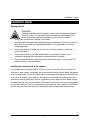
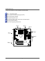
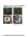
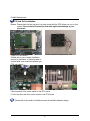
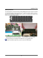
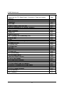
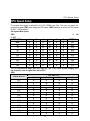
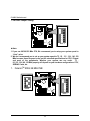
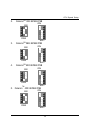
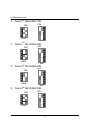
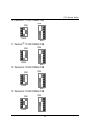
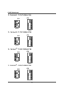
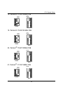
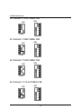
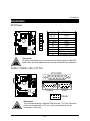
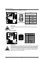
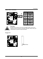
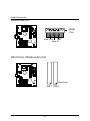
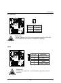
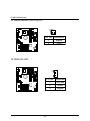
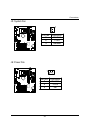
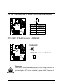
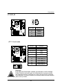
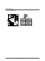
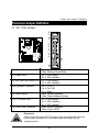
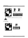
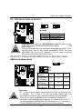
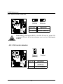
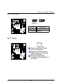
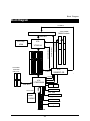
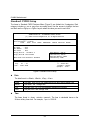
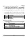
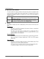
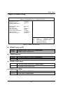
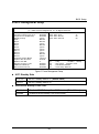
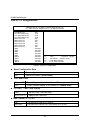
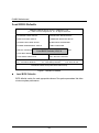
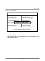
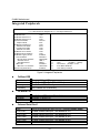
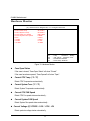
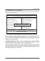
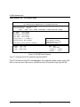
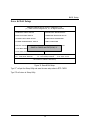
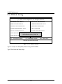
6VMM Socket 370 Processor Motherboard USER'S MANUAL Socket 370 Processor Motherboard REV. 1.2 First Edition R-12-01-001211 How This Manual Is Organized This manual is divided into the following sections: 1) Revision History Manual revision information 2) Item Checklist Product item list 3) Features Product information & specification 4) Hardware Setup Instructions on setting up the motherboard 5) Performance & Block Diagram Product performance & block diagram 6) Suspend to RAM Instructi ons STR installation 7) @BIOS TM & EasyTuneIIITM @BIOSTM & EasyTuneIIITM introduction 8) BIOS Setup Instructions on setting up the BIOS software 9) Appendix General reference Table Of Content Revision History P.1 Item Checklist P.2 Summary of Features P.3 Installation Guide P. 6 6VMM Motherboard Layout P.5 Page Index for CPU Speed Setup / Connectors / Panel and Jumper Definition P.6 Performance List P.35 Block Diagram P.38 Suspend to RAM Installation P.39 Memory Installation P.48 Page Index for BIOS Setup P.49 Appendix P.76 6VMM Motherboard Revision History Revision 1.2 Revision Note Initial release of the 6VMM motherboard user’s manual. Date Dec.2000 The author assumes no responsibility for any errors or omissions that may appear in this document nor does the author make a commitment to update the information contained herein. Third-party brands and names are the property of their respective owners. RM plc 1 Item Checklist Item Checklist þ The 6VMM motherboard þCable for IDE / floppy device þDiskettes or CD (TUCD) for motherboard driver & utility þ6VMM user’s manual 2 6VMM Motherboard Summary Of Features Form Factor Ÿ CPU Ÿ Chipset Ÿ Ÿ Ÿ Clock Generator Memory I/O Control Slots On-Board IDE Hardware Monitor PS/2 Connector BIOS Intel Pentium !!! 100/133MHz FSB, FC -PGA Intel CeleronTM 66MHz FSB, FC -PGA VIA Cyrix III 100/133MHz FSB, CPGA Ÿ Ÿ Ÿ Ÿ Ÿ Ÿ Ÿ 2nd cache in CPU (Depend on CPU) VT8601A (Pro Media) VT82C686A ICS 9248DF-39 66/100/133 MHz system bus speeds (PCI 33MHz) 75/83/112/124/140/150 MHz system bus speeds (reserved) 2 168-pin DIMM sockets. Supports PC-100 / PC-133 SDRAM and VCM SDRAM Supports up to 1.0GB DRAM Supports only 3.3V SDRAM DIMM VT82C686A 3 PCI slot supports 33MHz & PCI 2.2 compliant 1 AMR(Audio Modem Riser) slot 2 IDE bus master (DMA 33/ ATA 66 )IDE ports for up to 4 ATAPI devices Supports PIO mode 3, 4 (UDMA 33/ATA 66) IDE & ATAPI CD-ROM 1 floppy port supports 2 FDD with 360K, 720K,1.2M, 1.44M and 2.88M bytes 1 parallel ports supports SPP/EPP/ECP mode 2 serial ports (COM A & COMB) 4 USB ports 1 IrDA connector for IR CPU / System fan revolution detect CPU / System temperature detect System voltage detect (Vcore,Vcc3,Vcc,+12V) Ÿ Ÿ PS/2 Keyboard interface and PS/2 Mouse interface Licensed AMI BIOS, 2M bit flash ROM Ÿ Ÿ Ÿ Ÿ Ÿ Ÿ Ÿ Ÿ Ÿ Ÿ Ÿ Ÿ On-Board Peripherals 20.6 cm x 24.4 cm Micro ATX size form factor, 4 layers PCB. Socket 370 processor Ÿ 3 Summary of Features On-Board VGA Additional Features Ÿ Ÿ Ÿ Ÿ Ÿ Ÿ Ÿ Ÿ Ÿ Build Trident Blade 3D/Pro Media in VT8601A Support shared Memory Architecture Supports Wake-on-LAN (WOL) Supports Internal / External modem wake up Supports USB K/B or Mouse wake up from S3 Includes 3 fan power connectors. Poly fuse for keyboard over-current protection Support STR (Suspend-To-RAM) function Support @BIOS™ and EasyTuneIII™ (Optional) 4 6VMM Motherboard 6VMM Motherboard Layout 5 Installation Guide Installation Guide Getting Started WARNING! 1. 2. 3. 4. 5. Computer motherboards and expansion cards contain very delicate Integrated Circuit (IC) chips. To protect them against damage from static electricity, you should follow some precautions whenever you work on your computer. Unplug your computer when working on the inside. Use a grounded wrist strap before handling computer components. If you do not have one, touch both of your hands to a safely grounded object or to a metal object, such as the power supply case. Hold components by the edges and try not touch the IC chips, leads or connectors, or other components. Place components on a grounded antistatic pad or on the bag that came with the components whenever the components are separated from the system. Ensure that the ATX power supply is switched off before you plug in or remove the ATX power connector on the motherboard. Installing the motherboard to the chassis… If the motherboard has mounting holes, but they don’t line up with the holes on the base and there are no slots to attach the spacers, do not become alarmed you can still attach the spacers to the mounting holes. Just cut the bottom portion of the spacers (the spacer may be a little hard to cut off, so be careful of your hands). In this way you can still attach the motherboard to the base without worrying about short circuits. Sometimes you may need to use the plastic springs to isolate the screw from the motherboard PCB surface, because the circuit wire may be near by the hole. Be careful, don’t let the screw contact any printed circuit write or parts on the PCB that are near the fixing hole, otherwise it may damage the board or cause board malfunctioning. 6 6VMM Motherboard To set up your computer, you must complete the following steps: Step 1 - Set system jumpers Step 2- Install the Central Processing Unit (CPU) Step 3-Install memory modules Step 4-Install expansion cards Step 5-Connect ribbon cables, cabinet wires, and power supply Step 6-Set up BIOS software Step 7-Install supporting software tools Step 2 Step 3 Step 5 Step 1 Step 5 Step 5 Step 4 7 Installation Guide CPU Installation Please make sure the CPU type and speed is supported by your motherboard. CPU Bottom View CPU Top View Socket Actuation Lever 1.Pull the lever out and lift it up. 2.The notched corner should point toward the end of the lever. The CPU will only fit in the orientation as shown. 8 6VMM Motherboard CPU Heat Sink Installation: Beware: Please check that the heat sink is in good contact with the CPU before you turn on your system. Poor contact will cause over heat with might cause damage to your processor! 4.Use compliant fan approved by Intel. 3.Align CPU and insert it (Please refer to your heatsink installation manual for application of thermal grease to provide better heat conduction between your CPU and heatsink.) 5.Hook one end of the cooler bracket to the CPU socket. 6. Hook the other end of the cooler bracket to the CPU socket. (Please refer to the cooler’s installation manual for detailed installation steps) 9 Installation Guide Memory Installation The motherboard has 2 dual inline memory module (DIMM) sockets support 4 banks. The BIOS will automatically detects memory type and size. To install the memory module, just push it vertically into the DIMM Slot .The DIMM module can only fit in one direction due to the two notch. Memory size can vary between sockets. SDRAM 1. The DIMM slot has two notch, so the DIMM 2. Insert the DIMM memory module vertically into the DIMM slot. Then push it down. memory module can only fit in one direction. 3. Close the plastic clip at both edges of the DIMM slots to lock the DIMM module. Reverse the installation steps when you wish to remove the DIMM module. 10 6VMM Motherboard $ Page Index for CPU Speed Setup / Connectors / Panel and Jumper Definition CPU Speed Setup Connectors ATX Power COM A / COM B / VGA / LPT Port CN1(PS/2 Keyboard & PS/2 Mouse Connector) USB 1 Connector USB 2 Connector Floppy Port Game & Audio Port IDE 1 (Primary)/ IDE 2(Secondary) Port J1 (CPU Fan) J2 (IR) J3 (Internal Modem Card Ring On) J4 (Wake On LAN) J5 (System Fan) J6 (Power Fan) J10 (TEL) JP10 / LED1(STR LED Connector & DIMM LED) J11 (AUX_IN) JP11 (Front Audio) J12 (CD Audio Line In) Panel and Jumper Definition J7 (2x11 Pins Jumper) JP2 (Clear CMOS Function) JP3 (Case Open) JP4 (USB Device Wake Up Selection) JP5/JP6/JP7 (Onboard AC97& AMR Select) JP8 (BIOS Write Protection) JP9 (STR Function Enabled) JP12 (Front MIC) BAT1 (Battery) 11 Page P.12 P.20 P.20 P.20 P.21 P.21 P.22 P.22 P.23 P.23 P.24 P.24 P.25 P.25 P.26 P.26 P.27 P.27 P.28 P.28 P.29 P.30 P.30 P.31 P.31 P.32 P.32 P.33 P.33 P.34 P.34 CPU Speed Setup CPU Speed Setup The system bus speed is selectable at 66,100,133MHz and Auto. The user can select the system bus speed (SW1) and change the DIP switch (SW2) selection to set up the CPU speed for 300 – 1GB processor. Set System Bus Speed SW1: O : ON, X : OFF CPU (MHz) 1 2 3 4 5 6 PCI(MHz) Auto X X X X O O 33.3 66 O O X X X X 33.3 75 O O O X X X 37.5 83 O O X O X X 41.6 100 O X X X X X 33.3 112 O X O X X X 37.3 124 X X X O X X 31 133 X X X X X X 33.3 140 X X O O X X 35 150 X X O X X X 37.5 The CPU speed must match with the frequency ratio. It will cause system hanging up if the frequency ratio is higher than that of CPU. SW2: FREQ. RATIO X3 X 3.5 X4 X 4.5 X5 X 5.5 X6 X 6.5 X7 X 7.5 X8 X 8.5 X9 X 9.5 DIP SWITCH 1 2 3 4 O X O X O X O X O X O X O X X X O O X X O O X X O O X X O O X X X X O O O O X X X X O O O O O O X X X X X X X X 12 6VMM Motherboard F For Auto Jumper Setting: ON 6 5 4 3 2 1 SW1 « Note: 1. If you use 66/100/133 MHz CPU, We recommend you to setup your system speed to “Auto” value. 2. We don’t recommend you to set up your system speed to 75 , 83 , 112 , 124 , 140 ,150 MHz because these frequencies are not the standard specifications for CPU, Chipset and most of the peripherals. Whether your system can run under 75 , 83 ,112 ,124 ,140 ,150 MHz properly will depend on your hardware configurations: CPU, SDRAM, Cards, etc. 1. CeleronTM 300A/ 66 MHz FSB ON ON 6 5 4 3 2 1 1 2 3 4 SW2 SW2 SW1 13 CPU Speed Setup 2. CeleronTM 333/ 66 MHz FSB ON 1 2 3 4 6 5 4 3 2 1 ON SW2 3. TM SW1 Celeron 366/ 66 MHz FSB ON 1 2 3 4 6 5 4 3 2 1 ON SW2 4. TM SW1 Celeron 400/ 66 MHz FSB ON 1 2 3 4 6 5 4 3 2 1 ON SW2 TM SW1 5. Celeron 433/ 66 MHz FSB 1 2 3 4 SW2 ON 6 5 4 3 2 1 ON SW1 14 6VMM Motherboard 6. CeleronTM 466/ 66 MHz FSB ON 1 2 3 4 6 5 4 3 2 1 ON SW2 TM SW1 7. Celeron 500/ 66 MHz FSB ON 1 2 3 4 6 5 4 3 2 1 ON SW2 TM SW1 8. Celeron 533/ 66 MHz FSB ON 1 2 3 4 6 5 4 3 2 1 ON SW2 TM SW1 9. Celeron 566/ 66 MHz FSB 1 2 3 4 SW2 ON 6 5 4 3 2 1 ON SW1 15 CPU Speed Setup 10. Pentium !!! 500/100MHz FSB ON 1 2 3 4 6 5 4 3 2 1 ON SW2 SW1 11. Pentium !!! 550/100MHz FSB ON 1 2 3 4 6 5 4 3 2 1 ON SW2 SW1 12. Pentium !!! 600/100MHz FSB ON 1 2 3 4 6 5 4 3 2 1 ON SW2 SW1 13. Pentium !!! 650/100MHz FSB 1 2 3 4 SW2 ON 6 5 4 3 2 1 ON SW1 16 6VMM Motherboard 14. Pentium !!! 700/100MHz FSB ON 1 2 3 4 6 5 4 3 2 1 ON SW2 SW1 15. Pentium !!! 750/100MHz FSB ON 1 2 3 4 6 5 4 3 2 1 ON SW2 SW1 16. Pentium !!! 800/100MHz FSB ON 1 2 3 4 6 5 4 3 2 1 ON SW2 SW1 17. Pentium !!! 850/100MHz FSB 1 2 3 4 SW2 ON 6 5 4 3 2 1 ON SW1 17 CPU Speed Setup 18. Pentium !!! 533/133MHz FSB ON 1 2 3 4 6 5 4 3 2 1 ON SW2 SW1 19. Pentium !!! 600/133 MHz FSB ON 1 2 3 4 6 5 4 3 2 1 ON SW2 SW1 20. Pentium !!! 667/133MHz FSB ON 1 2 3 4 6 5 4 3 2 1 ON SW2 SW1 21. Pentium !!! 733/133MHz FSB 1 2 3 4 SW2 ON 6 5 4 3 2 1 ON SW1 18 6VMM Motherboard 22. Pentium !!! 800/133MHz FSB ON 1 2 3 4 6 5 4 3 2 1 ON SW2 SW1 23. Pentium !!! 866/133MHz FSB ON 1 2 3 4 6 5 4 3 2 1 ON SW2 SW1 24. Pentium !!! 933/133MHz FSB ON 1 2 3 4 6 5 4 3 2 1 ON SW2 SW1 25. Pentium !!! 1G Hz/133MHz FSB 1 2 3 4 SW2 ON 6 5 4 3 2 1 ON SW1 19 Connectors Connectors ATX Power Pin No. Definition 3,5,7,13, GND 15-17 1,2,11 3.3V 4,6,19,20 VCC 10 +12V 12 -12V 18 -5V 8 Power Good 9 5V SB stand by+5V 14 PS-ON(Soft On/Off) 10 20 1 11 Please note: AC power cord should only be connected to your power supply unit after ATX power cable and other related devices are firmly connected to the mainboard. COM A / COM B / VGA / LPT Port LPT PORT COM A VGA COM B Please note: This mainboard supports 2 standard COM ports and 1 LPT port. Device like printer can be connected to LPT port ; mouse and modem etc can be connected to COM ports. 20 6VMM Motherboard CN1:PS/2 Keyboard & PS/2 Mouse Connector PS/2 Mouse /Keyboard Pin No. Definition 1 Data 5 6 2 NC 4 3 3 GND 4 VCC(+5V) 2 1 5 Clock PS/2 Keyboard 6 NC PS/2 Mouse Please note: This mainboard supports standard PS/2 keyboard and PS/2 mouse interface connector. USB1: USB1 Connector 1 3 5 7 2 4 6 8 Please note: Pin No. Definition 1 USB PWR 2 USB PWR 3 USB D04 USB DT15 USB D0+ 6 USB DT1+ 7 GND 8 GND Before you connect your device(s) into USB connector(s), please make sure your device(s) such as USB keyboard, mouse, scanner, zip, buzzer..etc. have a standard USB interface. Also make sure your OS (Win 95 w/ USB supperment, Win98, Windows 2000, Windows ME, Win NT w/ SP 6) supports USB controller. If your OS does not support USB controller, please contact OS venders for possible patch or driver upgrade. For more information please contact your OS or device(s) venders. 21 Connectors USB2: USB 2 Connector 2 10 1 9 Pin No. 1 2 3 4 5 6 7 8 9 10 Definition USB PWR GND USB D2NC USB D2+ USB D3+ NC USB D3GND USB PWR Please Note: Be careful with the polarity of the front panel USB connector. Check the pin assignment while you connect the front panel USB cable. Please contact your nearest dealer for optional front panel USB cable. Floppy Port Red Line . 22 6VMM Motherboard Game & Audio Port GAME Port Line Out MIC Line In IDE1(Primary), IDE2(Secondary) Port Red Line IDE 1 IDE 2 23 Connectors J1: CPU Fan 1 Pin No. 1 2 3 Definition Control +12V SENSE Please note: A proper installation of the CPU cooler is essential to prevent the CPU from running under abnormal condition or damaged by overheating. J2:IR Pin No. Definition 1 VCC (+5V) 2 NC 3 IR Data Input 4 GND 5 IR Data Output 1 Please note: Warning make sure the pin 1 on the IR device is align with pin one the connector. 24 6VMM Motherboard J3:Internal Modem Card Ring On 1 Pin No. Definition 1 Signal 2 GND J4: Wake On LAN 1 Pin No. Definition 1 +5V SB 2 GND 3 Signal 25 Connectors J5: System Fan 1 Pin No. 1 2 3 Definition Control +12V SENSE J6: Power Fan 1 Pin No. 1 2 3 26 Definition Control +12V NC 6VMM Motherboard J10: TEL (The connector is for Modem with internal voice connector) 1 Pin No. Definition 1 Signal-In 2 GND 3 GND 4 Signal-Out JP10 / LED1: STR LED Connector & DIMM LED DIMM LED + STR LED Connector External. 1 Please note: Do not remove memory modules while DIMM LED is on. It might cause short or other unexpected damages due to the 3.3V stand by voltage. Remove memory modules only when STR function is disabled by jumper and AC Power cord is disconnected. 27 Connectors J11:AUX_IN 1 Pin No. 1 2 3 4 Definition AUX-L GND GND AUX-R JP11: Front Audio PIN NO. 1 2 2 16 1 15 Definition Incase speaker (R) Incase speaker (L) 3, 4,5,6,10,15 GND 7 +12V 8,16 NC 9 MIC 11 Front Audio (R) 13 Front Audio (L) 12 Rear Audio (R) 14 Rear Audio (L) Please Note : If you want to use “Front Audio” connector, you must move 11-12,13-14 Jumper. In order to utilize the front audio header, your chassis must have front audio connector. Also please make sure the pin assigment on the cable is the same as the pin assigment on the MB header. To find out if the chassis you are buying support front audio connector, please contact your dealer. 28 6VMM Motherboard J12: CD Audio Line In 1 Pin No. 1 2 3 4 29 Definition CD-L GND GND CD-R Panel and Jumper Definition Panel and Jumper Definition GN J7 : 2x11 Pins Jumper 1 SPK 1 1 GD RE PW P+ P− P− HD 1 GN (Green Switch) GD (Green LED) HD (IDE Hard Disk Active LED) SPK (Speaker Connector) RE (Reset Switch) P+P−P−(Power LED) PW (Soft Power Connector) 1 Open: Normal Operation Close: Entering Green Mode Pin 1: LED anode(+) Pin 2: LED cathode(−) Pin 1: LED anode(+) Pin 2: LED cathode(−) Pin 1: VCC(+) Pin 2- Pin 3: NC Pin 4: Data(−) Open: Normal Operation Close: Reset Hardware System Pin 1: LED anode(+) Pin 2: LED cathode(−) Pin 3: LED cathode(−) Open: Normal Operation Close: Power On/Off Please note: Please connect the power LED, PC speaker, reset switch and power switch etc of your chassis front panel to the front panel jumper according to the pin assignment above. 30 6VMM Motherboard JP2 : Clear CMOS Function 1 1 Normal (Default) Clear CMOS Pin No. Definition 1-2 Close Normal (Default) 2-3 Close Clear CMOS Please note: You may clear the CMOS data to its default values by this jumper. JP3: Case Open 1 Pin No. Definition 1 Signal 2 GND 31 Panel and Jumper Definition JP4: USB Device Wake up Selection 1 1 Normal (Default) Enable Pin No. Definition 1-2 close Normal (Default) 2-3 close USB Wake Up Please Note : (If you want to use “USB KB/MS Wake up from S3” function, you have to set the BIOS setting “USB KB/MS Wake up from S3” enabled, JP4 & JP9” enabled). *(Power on the computer and as soon as memory counting starts, press <Del>. You will enter BIOS Setup. Select the item “POWER MANAGEMENT SETUP”, then select “USB KB/MS Wake up from S3”. Remember to save the setting by pressing "ESC" and choose the “SAVE & EXIT SETUP” option.) JP5/JP6/JP7: Onboard AC97& AMR (Primary or Secondary) Select (AMRà à Audio Modem Riser) 1 1 JP6 1 JP5 Jumper Function Only AC97 (Default) Only AMR (Primary) AC97+MR (Secondary) JP7 JP5 JP6 JP7 1-2 1-2 1-2 3-4 3-4 2-3 1-2 3-4 1-2 1-2 Please note: JP7: 1-2 close: If you use software audio(onboard CODEC only), your modem riser must be “Secondary”. JP7: 2-3 close: If you don’t use onboard software audio, your audio/modem riser must be “Primary”. Mainboard’s software audio will be disabled. There are two types of AMR/MR card in the market, Primary and secondary. If your AMR/MR card is primary, JP7 should be set to 2-3, if you have secondary AMR/MR card JP7 should be set to 1-2. Warning! If Primary AMR/RM card is used, on-board audio will be disabled. 32 6VMM Motherboard JP8 : BIOS Write Protection 1 1 Normal (Default) Write Protection Pin No. Definition 1-2close Write Protection 2-3close Normal (Default) Please note:To flash/upgrade BIOS on this MB JP8 must be opened. We recommend JP8 to be set to close, whenever user is not try to flash/upgrade the BIOS. JP9: STR Function Selection 1 1 Disabled (Default) Enabled Pin No. Definition 2-3close STR Disabled (Default) 1-2close STR Enabled 33 Panel and Jumper Definition JP12 : Front MIC 1 1 Disable (Default) Enable Pin No. Definition 1-2close Disable (Default) 2-3close Enable BAT1 : Battery + CAUTION Danger of explosion if battery is incorrectly replaced. Replace only with the same or equivalent type recommended by the manufacturer. Dispose of used batteries according to the manufacturer’s instructions. 34 6VMM Motherboard Performance List The following performance data list is the testing results of some popular benchmark testing programs. These data are just referred by users, and there is no responsibility for different testing data values gotten by users. (The different Hardware & Software configuration will result in different benchmark testing results.) • CPU Intel Pentium III 1G Hz processor • DRA M (128 x 1)MB SDRAM (Mosel 0015PR V54C365804VCT7) • CACHE SIZE 256 KB included in CPU • DISPLAY Onboard VIA VT8601A 0046CD Graphics Controller • STORAGE Onboard IDE (IBM DTLA-307060) • O.S. Windows NTTM 4.0 SPK6a • DRIVER Display Driver at 1024 x 768 65536 colors 75Hz. VIA Bus Master IDE Driver Ver 2.1.49 Intel Pentium III 1G Hz (7.5x133) Processor Winbench99 CPU mark 99 78.6 FPU Winmark 99 5320 Business Disk Winmark 99 7980 Hi-End Disk Winmark 99 19700 Business Graphics Winmark 99 219 Hi-End Graphics Winmark 99 680 Winstone99 Business Winstone 99 42.9 Hi-End Winstone 99 53.5 35 Performance List • CPU Intel Celeron 800MHz processor • DRAM (128x1)MB SDRAM (Mosel 0015PR • CACHE SIZE 66KB included in CPU • DISPLAY Onboard VIA VT8601A 0046CD Graphics Controller • STORAGE Onboard IDE (IBM DTLA-307060) • O.S. Windows NTTM 4.0 SPK6a • DRIVER Display Driver at 1024 x 768 65536 colors 75Hz. VIA Bus Master IDE Driver Ver 2.1.49 V54C365804VCT7) Intel Celeron 800MHz (12x66) Processor Winbench99 CPU mark 99 51.4 FPU Winmark 99 4280 Business Disk Winmark 99 7380 Hi-End Disk Winmark 99 20000 Business Graphics Winmark 99 177 Hi-End Graphics Winmark 99 516 Winstone99 Business Winstone 99 34.8 Hi-End Winstone 99 41.3 36 6VMM Motherboard • CPU VIA Cyrix III 600MHz processor • DRAM (128x1)MB SDRAM (Mosel 0015PR • CACHE SIZE 256KB included in CPU • DISPLAY Onboard VIA VT8601A 0046CD Graphics Controller • STORAGE Onboard IDE (IBM DTLA-307060) • O.S. Windows NTTM 4.0 SPK6a • DRIVER Display Driver at 1024 x 768 65536 colors 75Hz. VIA Bus Master IDE Driver Ver 2.1.49 V54C365804VCT7) VIA Cyrix III 600MHz (4.5X133) Processor Winbench99 CPU mark 99 24.2 FPU Winmark 99 994 Business Disk Winmark 99 Hi-End Disk Winmark 99 6180 17700 Business Graphics Winmark 99 133 Hi-End Graphics Winmark 99 269 Winstone99 Business Winstone 99 Hi-End Winstone 99 37 26 18.7 Block Diagram Block Diagram 14.318MHz 3.3V DIMM DIMM Sockets Socket 370 CPU VIA On Chip VGA Ultra DMA 33/ATA66 IDE Ports 66 /100 /133 MHz 66 /100/133 MHz VT8601A 33 MHz PCI Bus VIA VT82C686A AC’97-Link ICS 9248DF-39 33 MHz USB Bus IDE Bus 66 /100 /133 MHz Host Bus 24MHz 48MHz 14.318MHz COM Ports LPT Port AC97 Floppy Port CODEC PS/2 KB/Mouse Game Port USB Ports 38 6VMM Motherboard Suspend To RAM Installation A.1 Introduce STR function: Suspend-to-RAM (STR) is a Windows 98 ACPI sleep mode function. When recovering from STR (S3) sleep mode, the system is able, in just a few seconds, to retrieve the last “state” of the system before it went to sleep and recover to that state. The “state” is stored in memory (RAM) before the system goes to sleep. During STR sleep mode, your system uses only enough energy to maintain critical information and system functions, primarily the system state and the ability to recognize various “wake up” triggers or signals, respectively. A.2 STR function Installation Please use the following steps to complete the STR function installation. Step-By-Step Setup Step 1: To utilize the STR function, the system must be in Windows 98 ACPI mode. Putting Windows 98 into ACPI mode is fairly easy. Setup with Windows 98 CD: A. Insert the Windows 98 CD into your CD-ROM drive, select Start, and then Run. B. Type (without quotes) “D:\setup ” in the window provided. Hit the enter key or click OK. C. After setup completes, remove the CD, and reboot your system (This manual assumes that your CD-ROM device drive letter is D:). 39 Suspend to RAM Installation Step 2: (If you want to use STR Function, please set jumper JP9 Closed.) 1 1 Disabled (Default) Enabled Pin No. Definition 2-3close STR Disabled (Default) 1-2close STR Enabled Step 3: Power on the computer and as soon as memory counting starts, press <Del>. You will enter BIOS Setup. Select the item “POWER MANAGEMENT SETUP”, then select “ACPI Sleep Type : S3 / STR”. Remember to save the settings by pressing "ESC" and choose the “SAVE & EXIT SETUP” option. Congratulation! You have completed the installation and now can use the STR function. 40 6VMM Motherboard A.3 How to put your system into STR mode? 1. There are two ways to accomplish this: Choose the “Stand by” item in the “Shut Down Windows” area. A. Press the “Start” button and then select “Shut Down” B. Choose the “Stand by” item and press “OK” 41 Suspend to RAM Installation 2. Define the system ”power on” button to initiate STR sleep mode: A. Double click “My Computer” and then “Control Panel” B. Double click the “ Power Management” item. 42 6VMM Motherboard C. Select the “Advanced” tab and “Standby” mode in Power Buttons. D. Restart your computer to complete setup. Now when you want to enter STR sleep mode, just momentarily press the “Power on” button. A.4 How to recover from the STR sleep mode? There are five ways to “wake up” the system: 1. 2. 3. 4. 5. Press the “Power On” button. Use the “PS/2 Mouse Power On” function. Use the “Resume by Alarm” function. Use the “Modem Ring On” function. Use the “Wake On LAN” function. 43 Suspend to RAM Installation A.5 Notices : 1. In order for STR to function properly, several hardware and software requirements must be satisfied: A. Your ATX power supply must comply with the ATX 2.01 specification (provide more than 720 mA 5V Stand-By current). B. 2. Your SDRAM must be PC-100 compliant. Jumper JP10 is provided to connect to the STR LED in your system chassis. [Your chassis may not provide this feature.] The STR LED will be illuminated when your system is in STR sleep mode. DIMM LED + STR LED Connector External. 1 44 Memory Installation Memory Installation The motherboard has 2 dual inline memory module (DIMM) sockets. The BIOS will automatically detects memory type and size. To install the memory module, just push it vertically into the DIMM Slot .The DIMM module can only fit in one direction due to the two notch. Memory size can vary between sockets. Install memory in any combination table: DIMM 168-pin SDRAM DIMM Modules DIMM 1 Supports 16 / 32 / 64 / 128 / 256 / 512 MB DIMM 2 Supports 16 / 32 / 64 / 128 / 256 / 512 MB Total System Memory (Max 1GB) 48 X 1 pcs X 1 pcs 6VMM Motherboard $ Page Index for BIOS Setup The Main Menu Standard CMOS Setup BIOS Features Setup Chipset Features Setup Power Management Setup PNP/ PCI Configuration Load BIOS Defaults Load Setup Defaults Integrated Peripherals Hardware Monitor Setup Supervisor Password / User Password IDE HDD Auto Detection Save & Exit Setup Exit Without Saving Page P.51 P.53 P.56 P.58 P.60 P.63 P.65 P.66 P.67 P.71 P.72 P.73 P.74 P.75 49 BIOS Setup BIOS Setup BIOS Setup is an overview of the BIOS Setup Program. The program that allows users to modify the basic system configuration. This type of information is stored in battery-backed CMOS RAM so that it retains the Setup information when the power is turned off. ENTERING SETUP Power ON the computer and press <Del> immediately will allow you to enter Setup. If the message disappears before you respond and you still wish to enter Setup, restart the system to try again by turning it OFF then ON or pressing the "RESET" bottom on the system case. You may also restart by simultaneously press <Ctrl> − <Alt>− <Del> keys. CONTROL KEYS <↑> <↓> <←> <→> <Esc> <+/PgUp> <-/PgDn> <F1> <F2> <F3> <F4> <F5> <F6> <F7> <F8> <F9> <F10> Move to previous item Move to next item Move to the item in the left hand Move to the item in the right hand Main Menu - Quit and not save changes into CMOS Status Page Setup Menu and Option Page Setup Menu - Exit current page and return to Main Menu Increase the numeric value or make changes Decrease the numeric value or make changes General help, only for Status Page Setup Menu and Option Page Setup Menu Reserved Reserved Reserved Restore the previous CMOS value from CMOS, only for Option Page Setup Menu Load the default CMOS value from BIOS default table, only for Option Page Setup Menu Load the Setup Defaults. Reserved Reserved Save all the CMOS changes, only for Main Menu 50 6VMM Motherboard GETTING HELP Main Menu The on-line description of the highlighted setup function is displayed at the bottom of the screen. Status Page Setup Menu / Option Page Setup Menu Press F1 to pop up a small help window that describes the appropriate keys to use and the possible selections for the highlighted item. To exit the Help Window press <Esc>. The Main Menu Once you enter AMI BIOS CMOS Setup Utility, the Main Menu (Figure 1) will appear on the screen. The Main Menu allows you to select from nine setup functions and two exit choices. Use arrow keys to select among the items and press <Enter> to accept or enter the sub-menu. AMIBIOS SIMPLE SETUP UTILITY -VERSION 1.24a ( C ) 1999 American Megatrends, Inc. All Rights Reserved STANDARD CMOS SETUP INTEGRATED PERIPHERALS BIOS FEATURES SETUP HARDWARE MONITOR SETUP CHIPSET FEATURES SETUP SUPERVISOR PASSWORD POWER MANAGEMENT SETUP USER PASSWORD PNP/PCI CONFIGURATION IDE HDD AUTO DETECTION LOAD BIOS DEFAULTS SAVE & EXIT SETUP LOAD SETUP DEFAULTS EXIT WITHOUT SAVING ESC : Quit ↑↓←→ : Select Item (Shift) F2 : Change Color F5 : Old Values F6 : Load BIOS Defaults F7: Load Setup Defaults F10: Save & Exit Time, Date, Hard Disk Type, … Figure 1: Main Menu • Standard CMOS Setup This setup page includes all the items in standard compatible BIOS. • BIOS Features Setup This setup page includes all the items of AMI special enhanced features. • Chipset Features Setup This setup page includes all the items of chipset special features. 51 BIOS Setup • Power Management Setup This setup page includes all the items of Green function features. • PnP/PCI Configurations This setup page includes all the configurations of PCI & PnP ISA resources. • Load BIOS Defaults Bios Defaults indicates the value of the system parameter which the system would be in the safe configuration. • Load Setup Defaults Setup Defaults indicates the value of the system parameter which the system would be in the most appropriate configuration. • Integrated Peripherals This setup page includes all onboard peripherals. • Hardware Monitor Setup This setup page is auto detect fan and temperature status. • Supervisor password Change, set, or disable password. It allows you to limit access to the system and Setup, or just to Setup. • User password Change, set, or disable password. It allows you to limit access to the system. • IDE HDD auto detection Automatically configure hard disk parameters. • Save & Exit Setup Save CMOS value settings to CMOS and exit setup. • Exit Without Saving Abandon all CMOS value changes and exit setup. 52 6VMM Motherboard Standard CMOS Setup The items in Standard CMOS Features Menu (Figure 2) are divided into 9 categories. Each category includes no, one or more than one setup items. Use the arrows to highlight the item and then use the <PgUp> or <PgDn> keys to select the value you want in each item. AMIBIOS SETUP – STANDARD CMOS SETUP ( C ) 1999 American Megatrends, Inc. All Rights Reserved Date (mm/dd/yyyy) : Tue Jan 25, 2000 Time (hh/mm/ss) : 10:36:24 TYPE SIZE CYLS HEAD PRECOMP LANDZ SECTOR MODE Pri Master : Auto Pri Slave : Auto Sec Master : Auto Sec Slave : Auto Floppy Drive A: 1.44 MB 3 ½ Floppy Drive B: Not Installed Base Memory : 640 Kb Other Memory: 384 Kb Extended Memory: 30Mb Total Memory: 31Mb Boot Sector Virus Protection : Disabled Month: Jan – Dec Day: 01 – 31 Year : 1990– 2099 ESC : Exit ↑↓ : Select Item PU/PD/+/ – : Modify (Shift)F2 : Color Figure 2: Standard CMOS Setup • Date The date format is <Week>, <Month>, <Day>, <Year>. Week Month Day Year The week, from Sun to Sat, determined by the BIOS and is display -only The month, Jan. Through Dec. The day, from 1 to 31 (or the maximum allowed in the month) The year, from 1990 through 2099 • Time The times format in <hour> <minute> <second>. The time is calculated bas e on the 24-hour military-time clock. For example, 1 p.m. is 13:00:00. 53 BIOS Setup • IDE Primary Master, Slave / Secondary Master, Slave The category identifies the types of hard disk from drive C to F that has been installed in the computer. There are two types: auto type, and user definable type. User type is user-definable; Auto type which will automatically detect HDD type. Note that the specifications of your drive must match with the drive table. The hard disk will not work properly if you enter improper information for this category. If you select User Type, related information will be asked to enter to the following items. Enter the information directly from the keyboard and press <Enter>. Such information should be provided in the documentation form your hard disk vendor or the system manufacturer. CYLS. Number of cylinders HEADS number of heads PRECOMP write precomp LANDZONE Landing zone SECTORS number of sectors If a hard disk has not been installed select NONE and press <Enter>. • Drive A type / Drive B type The category identifies the types of floppy disk drive A or drive B that has been installed in the computer. None 360K, 5.25 in. 1.2M, 5.25 in. 720K, 3.5 in. 1.44M, 3.5 in. 2.88M, 3.5 in. No floppy drive installed 5.25 inch PC-type standard drive; 360K byte capacity. 5.25 inch AT-type high-density drive; 1.2M byte capacity (3.5 inch when 3 Mode is Enabled). 3.5 inch double-sided drive; 720K byte capacity 3.5 inch double-sided drive; 1.44M byte capacity. 3.5 inch double-sided drive; 2.88M byte capacity. 54 6VMM Motherboard • Boot Sector Virus Protection If it is set to enable, the category will flash on the screen when there is any attempt to write to the boot sector or partition table of the hard disk drive. The system will halt and the following error message will appear in the mean time. You can run anti -virus program to locate the problem. Enabled Disabled Activate automatically when the system boots up causing a warning message to appear when anything attempts to access the boot sector or hard disk partition table No warning message to appear when anything attempts to access the boot sector or hard disk partition table. (Default Value) • Memory The category is display -only which is determined by POST (Power On Self Test) of the BIOS. Base Memory The POST of the BIOS will determine the amount of base (or conventional) memory installed in the system. The value of the base memory si typically 512 K for systems with 512 K memory installed on the motherboard, or 640 K for systems with 640 K or more memory installed on the motherboard. Extended Memory The BIOS determines how much extended memory is present during the POST. This is the amount of memory located above 1 MB in the CPU's memory address map. Other Memory This refers to the memory located in the 640 K to 1024 K address space. This is memory that can be used for different applications. DOS uses this area to load device drivers to keep as much base memory free for application programs. Most use for this area is Shadow RAM 55 BIOS Setup BIOS Features Setup AMIBIOS SETUP – BIOS FEATURES CMOS SETUP ( C ) 1999 American Megatrends, Inc. All Rights Reserved 1st Boot Device 2nd Boot Device 3rd Boot Device S.M.A.R.T for Hard Disks BootUp Num -Lock Floppy Drive Seek Password Check Processor Serial Number :Floppy :IDE-0 :CDROM :Disabled :On :Disabled :Setup :Disabled ESC F1 F5 F6 F7 : Quit ↑↓← →: Select Item : Help PU/PD/+/ - : Modify : Old Values (Shift)F2 :Color : Load BIOS Defaults : Load Setup Defaults Figure 3: BIOS Features Setup • 1st / 2nd / 3rd Boot Device The default value is Floppy or LS / ZIP A: or ATAPI ZIP C: or CDROM or SCSI or NET WORK or IDE-0~IDE-3 or USB FDD or Disabled. Floppy LS / ZIP A: CDROM SCSI NETWORK IDE-0~IDE-3 Disabled ATAPI ZIP C: USB FDD Boot Device by Floppy. Boot Device by LS / ZIP A:. Boot Device by CDROM. Boot Device by SCSI. Boot Device by NETWORK. Boot Device by IDE -0~IDE-3. Boot Device by Disabled. Boot Device by ATAPI ZIP C:. Boot Device by USB FDD. • S.M.A.R.T. for Hard Disks Enable Disable Enable S.M.A.R.T. Hard for Disks. Disable S.M.A.R.T. Hard for Disks. (Default Value) 56 6VMM Motherboard • Boot Up Num-Lock On Off • Keypad is number keys. (Default Value) Keypad is arrow keys. Floppy Drive Seek During POST, BIOS will determine if the floppy disk drive installed is 40 or 80 tracks. 360 type is 40 tracks while 720 , 1.2 and 1.44 are all 80 tracks. Enabled Disabled BIOS searches for floppy disk drive to determine if it is 40 or 80 tracks. Note that BIOS can not tell from 720, 1.2 or 1.44 drive type as they are all 80 tracks. BIOS will not search for the type of floppy disk drive by track number. Note that there will not be any warning message if the drive installed is 360. (Default Value) • Password Check Setup Always Set Password Check to Setup. (Default Value) Set Password Check to Always. • Processor Serial Number Disabled Enabled Disabled CPU Serial Number. (Default Value) Enabled CPU Serial Number. 57 BIOS Setup Chipset Features Setup AMIBIOS SETUP –CHIPSET FEATURE CMOS SETUP ( C ) 1999 American Megatrends, Inc. All Rights Reserved *** DRAM Timing *** DRAM Frequency SDRAM CAS# Latency :Disabled :100 MHz :3 DRAM Integrity Mode AGP Mode AGP Fast Write AGP Aperture Size ClkGen Spread Spectrum USB Controller USB Legacy Support :Non-ECC :2X :Disabled :64MB :Disabled :All USB Port :Disabled SDRAM Timing by SPD ESC : Quit ↑↓←→: Select Item F1 : Help PU/PD/+/ - : Modify F5 : Old Values (Shift)F2 :Color F6 : Load BIOS Defaults F7 : Load Setup Defaults Figure 4: Chipset Features Setup • SDRAM Timing by SPD Disabled Enabled Disabled SDRAM Timing by SPD. (Default Value) Enabled SDRAM Timing by SPD. • DRAM Frequency 100MHz 133MHz Set DRAM Frequency is 100MHz. (Default Value) Set DRAM Frequency is 133MHz. • SDRAM CAS# Latency 3 2 For Slower SDRAM DIMM module. (Default Value) For Fastest SDRAM DIMM module. • DRAM Integrity Mode ECC Non-ECC For 72 bit ECC type DIMM Model. Normal Setting. (Default Value) 58 6VMM Motherboard • AGP Mode 1X 2X Set AGP Mode is 1X. Set AGP Mode is 2X. (Default Value) • AGP Fast Write Disabled Enabled Disabled AGP Fast Write (Default Value) Enabled AGP Fast Write • AGP Aperture Size 4MB 8MB 16MB 32MB 64MB 128MB 256MB Set AGP Aperture Size to 4MB. Set AGP Aperture Size to 8 MB. Set AGP Aperture Size to 16 MB. Set AGP Aperture Size to 32 MB. Set AGP Aperture Size to 64 MB. (Default Value) Set AGP Aperture Size to 128 MB. Set AGP Aperture Size to 256 MB. • ClkGen Spread Spectrum Enabled Disabled Enabled ClkGen Spread Spectrum. Normal function. (Default Value) • USB Controller All USB Port USB Port 0&1 USB Port 2&3 Disabled Set USB Controller Function used all USB Port. (Default Value) Set USB Controller Function used USB Port 0&1. Set USB Controller Function used USB Port 2&3. USB Controller Function Disabled. • USB Legacy Support Keyboard / FDD KB / Mouse / FDD Disabled Set USB Legacy Support Keyboard / FDD. Set USB Legacy Support Keyboard / Mouse / FDD. Disabled USB Legacy Support Function. (Default Value) 59 BIOS Setup Power Management Setup AMIBIOS SETUP –POWER MANAGEMENT SETUP ( C ) 1999 American Megatrends, Inc. All Rights Reserved ACPI Standby State USB Device Wakeup From S3-S5 Suspend Time Out(Minute) Display Activity IRQ3 IRQ 4 IRQ 5 IRQ 7 IRQ 9 IRQ 10 IRQ 11 IRQ 13 IRQ 14 IRQ 15 Soft-off by Power Button System after AC Back Modem Use IRQ Resume On Ring / LAN PME Event Wake up RTC Alarm Power On :S1/POS :Disabled :Disabled :Ignore :Monitor :Monitor :Ignore :Monitor :Ignore :Ignore :Ignore :Ignore :Monitor :Ignore : Instant off :Soft-Off :4 :Enabled :Enabled :Disabled RTC RTC RTC RTC Alarm Date Alarm Hour Alarm Minute Alarm Second :15 :12 :30 :30 ESC F1 F5 F6 F7 : Quit ↑↓←→: Select Item : Help PU/PD/+/ - : Modify : Old Values (Shift)F2 :Color : Load BIOS Defaults : Load Setup Defaults Figure 5: Power Management Setup • ACPI Standby State S1/POS S3/STR Set ACPI Standby State is S1. (Default Value) Set ACPI Standby State is S3. • USB Device Wakeup From S3-S5 Disabled Enabled Disabled USB KB Wakeup From S3-S5 function. (Default Value) Enabled USB KB Wakeup From S3-S5 function. 60 6VMM Motherboard • Suspend Time Out (Minute.) Disabled 1 2 4 8 10 20 30 40 50 60 Disabled Suspend Time Out Function. (Default Value) Enabled Suspend Time Out after 1min. Enabled Suspend Time Out after 2min. Enabled Suspend Time Out after 4min. Enabled Suspend Time Out after 8min. Enabled Suspend Time Out after 10min. Enabled Suspend Time Out after 20min. Enabled Suspend Time Out after 30min. Enabled Suspend Time Out after 40min. Enabled Suspend Time Out after 50min. Enabled Suspend Time Out after 60min. • Display Activity Ignore Monitor Ignore Display Activity . (Default Value) Monitor Display Activity. • IRQ 3~IRQ15 Ignore Monitor Ignore IRQ3 ~IRQ15. Monitor IRQ3~IRQ15. • Soft-off by Power Button Instant off Delay -4Sec Soft switch ON/OFF for Power Button. (Default Value) Soft switch ON 4 Sec for Power off. • System after AC Back Power-Off Full-On Memory Set Restore on AC/Power Loss is Power off. Set Restore on AC/Power Loss is Full on. Set Restore on AC/Power Loss is Last state mode. (Default Value) • MODEM Use IRQ NA 3 4 5 7 Set MODEM Use IRQ to NA. Set MODEM Use IRQ to 3. Set MODEM Use IRQ to 4. (Default Value) Set MODEM Use IRQ to 5. Set MODEM Use IRQ to 7. 61 BIOS Setup • Modem Ring On/ LAN Disabled Enabled Disabled Modem Ring On / Wake On LAN function. Enabled Modem Ring On / Wake On LAN function. (Default Value) • PME Event Wake up Disabled Enabled Disabled PME Event Wake up function. Enabled PME Event Wake up function. (Default Value) • RTC Alarm Power On You can set “RTC Alarm Power On” item to enabled and key in Data/time to power on system. Disabled Enabled Disable this function. (Default Value) Enable alarm function to POWER ON system. If RTC Alarm Lead To Power On is Enabled. RTC Alarm Date : RTC Alarm Hour: RTC Alarm Minute : RTC Alarm Second : Every Day,1~31 0~23 0~59 0~59 62 6VMM Motherboard PnP/PCI Configurations AMIBIOS SETUP –PNP/PCI CONFIGURATION SETUP ( C ) 1999 American Megatrends, Inc. All Rights Reserved Reset Configuration Data VGA Boot From PCI Slot1 IRQ Priority PCI Slot2 IRQ Priority PCI Slot3 IRQ Priority DMA Channel 0 DMA Channel 1 DMA Channel 3 DMA Channel 5 DMA Channel 6 DMA Channel 7 IRQ3 IRQ4 IRQ5 IRQ7 IRQ9 IRQ10 IRQ11 IRQ14 IRQ15 :No :PCI :Auto :Auto :Auto :PnP :PnP :PnP :PnP :PnP :PnP :PCI/PnP :PCI/PnP :PCI/PnP :PCI/PnP :PCI/PnP :PCI/PnP :PCI/PnP :PCI/PnP :PCI/PnP ESC F1 F5 F6 F7 : Quit ↑↓←→: Select Item : Help PU/PD/+/ - : Modify : Old Values (Shift)F2 :Color : Load BIOS Defaults : Load Setup Defaults Figure 6: PnP/PCI Configuration • Reset Configuration Data Yes No Reset configuration data. Disabled this function. (Default Value) • VGA Boot From Onchip AGP PCI Primary Graphics Adapter From Add-on AGP. Primary Graphics Adapter From OnBoard PCI. (Default Value) • PCI Slot 1 ~ Slot 3 IRQ Priority Auto 3,4,5.7,9,10,11 Auto Set PCI Slot 1~Slot 3 IRQ Priority Setting PCI Slot 1~Slot 3 IRQ. • DMA Channel (0,1,3,5,6,7) PnP ISA / EISA The resource is used by PnP device. The resource is used by ISA / EISA device (PCI or ISA). 63 BIOS Setup • IRQ -( 3,4,5,7,9, 10,11), assigned to ( “ISA / EISA” or “PCI/PnP” ) ISA/ EISA PCI / PnP The resource is used by Legacy ISA device. The resource is used by PCI/ PnP device. 64 6VMM Motherboard Load BIOS Defaults AMIBIOS SIMPLE SETUP UTILITY -VERSION 1.24a ( C ) 1999 American Megatrends, Inc. All Rights Reserved STANDARD CMOS SETUP INTEGRATED PERIPHERALS BIOS FEATURES SETUP HARDWARE MONITOR SETUP CHIPSET FEATURES SETUP SUPERVISOR PASSWORD POWER MANAGEMENT SETUP USER PASSWORD PNP/PCI CONFIGURATION IDE HDD AUTO DETECTION LOAD BIOS DEFAULTS SAVE & EXIT SETUP LOAD SETUP DEFAULTS EXIT WITHOUT SAVING Load BIOS Defaults (Y/N)? N ESC : Quit ↑↓→← : Select Item (Shift) F2 : Change Color F5 : Old Values F6 : Load BIOS Defaults F7: Load Setup Defaults F10: Save & Exit Load BIOS Default except Standard CMOS Setup Figure 7: Load BIOS Defaults • Load BIOS Defaults BIOS defaults contain the most appropriate values of the system parameters that allow minimum system performance. 65 BIOS Setup Load Setup Defaults AMIBIOS SIMPLE SETUP UTILITY -VERSION 1.24a ( C ) 1999 American Megatrends, Inc. All Rights Reserved STANDARD CMOS SETUP INTEGRATED PERIPHERALS BIOS FEATURES SETUP HARDWARE MONITOR SETUP CHIPSET FEATURES SETUP SUPERVISOR PASSWORD POWER MANAGEMENT SETUP USER PASSWORD PNP/PCI CONFIGURATION Load IDE HDD AUTONDETECTION SETUP Defaults (Y/N)? LOAD BIOS DEFAULTS SAVE & EXIT SETUP LOAD SETUP DEFAULTS EXIT WITHOUT SAVING ESC : Quit ↑↓→← : Select Item (Shift) F2 : Change Color F5 : Old Values F6 : Load BIOS Defaults F7: Load Setup Defaults F10: Save & Exit Load Setup Default except Standard CMOS Setup Figure 8: Load Setup Defaults • Load Setup Defaults Selecting this field loads the factory defaults for BIOS and Chipset Features which the system automatically detects. 66 6VMM Motherboard Integrated Peripherals AMIBIOS SETUP –INTEGRATED PERIPHERAL ( C ) 1999 American Megatrends, Inc. All Rights Reserved OnBoard IDE OnBoard FDC OnBoard Serial Port 1 OnBoard Serial Port 2 Serial Port2 Mode Duplex Mode OnBoard Parallel Port Parallel Port Mode Parallel Port DMA Parallel Port IRQ OnBoard AC’97 Audio OnBoard MC’97 Modem OnBoard Legacy Audio Sound Blaster SB I/O Base Address SB IRQ Select SB DMA Select MPU-401 MPU-401 I/O Address Game Port(200h-207h) :Both :Auto :Aut o :Auto :Normal :N/A :Auto :ECP :Auto :Auto :Auto :Auto :Enabled :Disabled :220h-22Fh :IRQ 5 :DMA1 :Disabled :330h-333h :Enabled ESC F1 F5 F6 F7 : Quit ↑↓←→: Select Item : Help PU/PD/+/ - : Modify : Old Values (Shift)F2 :Color : Load BIOS Defaults : Load Setup Defaults Figure 9: Integrated Peripherals • OnBoard IDE Disabled Both Primary Secondary • On Board FDC Auto Disabled Enabled • Disabled OnBoard IDE Set OnBoard IDE is Both (Default Value). Set OnBoard IDE is Primary Set OnBoard IDE is Secondary Set On Board FDC is Auto (Default Value). Disabled On Board FDC Enabled On Board FDC Onboard Serial Port 1 Auto 3F8/COM1 2F8/COM2 3E8/COM3 2E8/COM4 Disabled BIOS will automatically setup the port 1 address (Default Value). Enable onboard Serial port 1 and address is 3F8. Enable onboard Serial port 1 and address is 2F8. Enable onboard Serial port 1 and address is 3E8. Enable onboard Serial port 1 and address is 2E8. Disable onboard Serial port 1. 67 BIOS Setup • Onboard Serial Port 2 Auto 3F8/COM1 2F8/COM2 3E8/COM3 2E8/COM4 Disabled • BIOS will automatically setup the port 2 address (Default Value). Enable onboard Serial port 2 and address is 3F8. Enable onboard Serial port 2 and address is 2F8. Enable onboard Serial port 2 and address is 3E8. Enable onboard Serial port 2 and address is 2E8. Disable onboard Serial port 2. Serial Port 2 Mode ASKIR IrDA Normal • Duplex Mode Half Duplex N/A Full Duplex • Using Parallel port as Enhanced Parallel Port. Using Parallel port as Extended Capabilities Port. (Default Value) Normal Operation. Parallel Port DMA Auto N/A 3 1 0 • Enable On Board LPT port and address is 378. Enable On Board LPT port and address is 278. Enable On Board LPT port and address is 3BC. Set On Board LPT port is Auto. (Default Value). Disable On Board LPT port. Parallel Port Mode EPP ECP Normal • IR Function Duplex Half. Disabled this function. (Default Value) IR Function Duplex Full. On Board Parallel port 378 278 3BC Auto Disabled • Set onboard I/O chip Serial Port 2 to ASKIR Mode. Set onboard I/O chip Serial Port 2 to IrDA Mode. Set onboard I/O chip Serial Port 2 to Normal Mode. (Default Value) Set Auto to parallel port mode DMA Channel. (Default Value) Disabled this function. Set Parallel Port DMA is 3. Set Parallel Port DMA is 1. Set Parallel Port DMA is 0. Parallel Port IRQ 7 Auto 5 Set Parallel Port IRQ is 7. Set Auto to parallel Port IRQ DMA Channel. . (Default Value). Set Parallel Port IRQ is 5. 68 6VMM Motherboard • OnBoard AC’97 Audio Auto Disabled • OnBorard MC’97 Modem Auto Disabled • Set MC’97 Modem to Auto (Default Value). Disabled MC’97 Modem. OnBorard Legacy Audio Enabled Disabled • Set AC’97 Audio to Auto (Default Value). Disabled AC’97 Audio. Enabled OnBoard Legacy Audio. (Default Value) Disabled OnBoard Legacy Audio. Sound Blaster Enabled Disabled Enabled Sound Blaster. Disabled Sound Blaster. (Default Value) • SB I/O Base Address 220h-22Fh 280h-28Fh 260h-26Fh 240h-24Fh • Set SB I/O Base Address is 220h-22Fh. (Default Value) Set SB I/O Base Address is 280h-28Fh. Set SB I/O Base Address is 260h-26Fh. Set SB I/O Base Address is 240h-24Fh. SB IRQ Select IRQ 5 / 7 / 9 / 10. (Default Value: 5 ) • SB DMA Select DMA 0 / 1 / 2/ 3. (Default Value: 1 ) • MPU-401 Enabled Disabled Enabled MPU-401. Disabled MPU-401. (Default Value) 69 BIOS Setup • MUP-401 I/O Address 330h-333h 300h-303h 310h-313h 320h-323h • Set MUP-401 I/O Address is 330h-333h. (Default Value) Set MUP-401 I/O Address is 300h-303h. Set MUP-401 I/O Address is 310h-313h. Set MUP-401 I/O Address is 320h-323h. Game Port (200h-207h) Disabled Enabled Disabled Game Port (200h-207h). Enabled Game Port (200h-207h). (Default Value) 70 6VMM Motherboard Hardware Monitor AMIBIOS SETUP –HARDWARE MONITOR ( C ) 1999 American Megatrends, Inc. All Rights Reserved Case Open Status :Opened Current CPU Temp. :36°C/96°F Current System Temp. :28°C/82°F Current CPU Fan Speed :5487 RPM Current System Fan Speed :0 RPM Vcore :2.075V +3.300V :3.590V +5.000V :5.119V +12.000V :11.926V ESC F1 F5 F6 F7 : Quit ↑↓←→: Select Item : Help PU/PD/+/ - : Modify : Old Values (Shift)F2 :Color : Load BIOS Defaults : Load Setup Defaults Figure 10: Hardware Monitor • Case Open Status If the case is closed, “Case Open Status” will show “Closed”. If the case have been opened, “Case Opened” will show “Open”. • Current CPU Temp. (°° C / ° F) Detect CPU Temperature automatically. • Current System Tem. (°° C / ° F) Detect System Temperature automatically. • Current CPU FAN Speed Detect CPU Fan speed status automatically . • Current System FAN Speed Detect System Fan speed status automatically . • Current Voltage (V) VCORE / +3.3V / +12V / +5V Detect system’s voltage status automatically. 71 BIOS Setup Set Supervisor / User Password When you select this function, the following message will appear at the center of the screen to assist you in creating a password. AMIBIOS SIMPLE SETUP UTILITY -VERSION 1.24a ( C ) 1999 American Megatrends, Inc. All Rights Reserved STANDARD CMOS SETUP INTEGRATED PERIPHERALS BIOS FEATURES SETUP HARDWARE MONITOR SETUP CHIPSET FEATURES SETUP SUPERVISOR PASSWORD POWER MANAGEMENT SETUP USER PASSWORD PNP/PCI CONFIGURATION IDE HDD AUTO DETECTION LOAD BIOS DEFAULTS SAVE & EXIT SETUP LOAD SETUP DEFAULTS EXIT WITHOUT SAVING Enter new supervisor password: ESC : Quit ↑↓→← : Select Item (Shift) F2 : Change Color F5 : Old Values F6 : Load BIOS Defaults F7: Load Setup Defaults F10: Save & Exit Chang /Set /Disabled Password Figure 11: Password Setting Type the password, up to eight characters, and press <Enter>. The password typed now will clear the previously entered password from CMOS memory. You will be asked to confirm the password. Type the password again and press <Enter>. You may also press <Esc> to abort the selection and not enter a password. To disable password, just press <Enter> when you are prompted to enter password. A message “PASSWORD DISABLED” will appear to confirm the password being disabled. Once the password is disabled, the system will boot and you can enter Setup freely. If you select “Always” at ”Password Check” Option in BIOS Features Setup Menu, you will be prompted for the password every time the system is rebooted or any time you try to enter Setup Menu. If you select “Setup” at “Password Check” Option in BIOS Features Setup Menu, you will be prompted only when you try to enter Setup. 72 6VMM Motherboard IDE HDD AUTO Detection AMIBIOS SETUP – STANDARD CMOS SETUP ( C ) 1999 American Megatrends, Inc. All Rights Reserved Date (mm/dd/yyyy) : Tue Jan 25, 2000 Time (hh/mm/ss) : 10:36:24 TYPE SIZE CYLS HEAD Pri Master : Pri Slave : Sec Master : Sec Slave : PRECOMP LANDZ SECTOR MODE Not Installed Not Installed Not Installed Not Installed Floppy Drive A: 1.44 MB 3 ½ Floppy Drive B: Not Installed Base Memory : 640 Kb Other Memory: 384 Kb Extended Memory: 31Mb Total Memory: 32Mb Boot Sector Virus Protection : Disabled Month: Jan – Dec Day: 01 – 31 Year : 1990– 2099 ESC : Exit ↑↓ : Select Item PU/PD/+/ – : Modify (Shift)F2 : Color Figure 12: IDE HDD Auto Detection Type "Y" will accept the H.D.D. parameter reported by BIOS. Type "N" will keep the old H.D.D. parameter setup. If the hard disk cylinder number is over 1024, then the user can select LBA mode or LARGER mode for DOS partition larger than 528 MB. 73 BIOS Setup Save & Exit Setup AMIBIOS SIMPLE SETUP UTILITY -VERSION 1.24a ( C ) 1999 American Megatrends, Inc. All Rights Reserved STANDARD CMOS SETUP INTEGRATED PERIPHERALS BIOS FEATURES SETUP HARDWARE MONITOR SETUP CHIPSET FEATURES SETUP SUPERVISOR PASSWORD POWER MANAGEMENT SETUP USER PASSWORD PNP/PCI CONFIGURATION IDE HDD AUTO DETECTION SAVE to CMOS and EXIT(Y/N)? Y LOAD BIOS DEFAULTS SAVE & EXIT SETUP LOAD SETUP DEFAULTS EXIT WITHOUT SAVING ESC : Quit ↑↓→← : Select Item (Shift) F2 : Change Color F5 : Old Values F6 : Load BIOS Defaults F7: Load Setup Defaults F10: Save & Exit Save Data to CMOS & Exit Setup Figure 13: Save & Exit Setup Type "Y" will quit the Setup Utility and save the user setup value to RTC CMOS. Type "N" will return to Setup Utility. 74 6VMM Motherboard Exit Without Saving AMIBIOS SIMPLE SETUP UTILITY -VERSION 1.24a ( C ) 1999 American Megatrends, Inc. All Rights Reserved STANDARD CMOS SETUP INTEGRATED PERIPHERALS BIOS FEATURES SETUP HARDWARE MONITOR SETUP CHIPSET FEATURES SETUP SUPERVISOR PASSWORD POWER MANAGEMENT SETUP USER PASSWORD PNP/PCI CONFIGURATION IDE HDD AUTO DETECTION LOAD BIOS DEFAULTS SAVE & EXIT SETUP Quit without saving (Y/N) ? N LOAD SETUP DEFAULTS EXIT WITHOUT SAVING ESC : Quit ↑↓→← : Select Item (Shift) F2 : Change Color F5 : Old Values F6 : Load BIOS Defaults F7: Load Setup Defaults F10: Save & Exit Abandon all Datas & Exit Setup Figure 14: Exit Without Saving Type "Y" will quit the Setup Utility without saving to RTC CMOS. Type "N" will return to Setup Utility. 75 Appendix Appendix Appendix : Acronyms Acor. ACPI POST LAN ECP APM DMA MHz ESCD CPU SMP USB OS ECC IDE SCI LBA EMC BIOS SMI IRQ NIC A.G.P. S.E.C.C. LED EPP CMOS I/O ESD OEM SRAM VID DMI MIDI IOAPIC DIMM DRAM PAC AMR Meaning Advanced Configuration and Power Interface Power-On Self Test Local Area Network Extended Capabilities Port Advanced Power Management Direct Memory Access Megahertz Extended System Configuration Data Central Processing Unit Symmetric Multi-Processing Universal Serial Bus Operating System Error Checking and Correcting Integrated Dual Channel Enhanced Special Circumstance Instructions Logical Block Addressing Electromagnetic Compatibility Basic Input / Output System System Management Interrupt Interrupt Request Network Interface Card Accelerated Graphics Port Single Edge Contact Cartridge Light Emitting Diode Enhanced Parallel Port Complementary Metal Oxide Semiconductor Input / Output Electrostatic Discharge Original Equipment Manufacturer Static Random Access Memory Voltage ID Desktop Management Interface Musical Interface Digital Interface Input Output Advanced Programmable Input Controller Dual Inline Memory Module Dynamic Random Access Memory PCI A.G.P. Controller Audio Modem Riser 76 6VMM Motherboard Acor. PCI RIMM DRM ISA MTH CRIMM Meaning Peripheral Component Interconnect Rambus in-line Memory Module Dual Retention Mechanism Industry Standard Architecture Memory Translator Hub Continuity RIMM 77