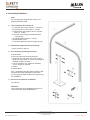
1
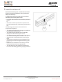
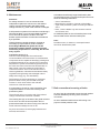
Assembly/Installation instructions
Operating Instructions
for
Söll fall protection systems
Typ „Söll-GlideLocTM“
twisted change overrail
Issue: 09.10.2008
SE 28
Safety At Height Limited
Unit 1 Pennine View, Marple, Stockport
Cheshire, SK67JW
Tel: +44(0)161 446 5615
1
www.safety-height.co.uk
Table of contents
1. Introduction
3
2. Equipment description
3
3. Safety precautions
4
4. Assembly/Installation
5
4.1 The installation kit consists of:
5
4.2 Equipment required for easy mounting:
5
4.3 For mounting to existing structures
5
4.4 Personnel required for installation
5
4.5 General assembly instructions
6
4.6 Minimum bolt dimensions
for the installation of ladders:
6
4.7 Instructions for assembling ladders
6
4.9 Assembling the twisted change-over rail
7
4.10Installation of the climbing block
8
4.11 Retrofitting the roof transfer system
to an existing climbing system
8
4.12Torque ranges:
9
5. Inspection and approval
10
6. Maintenance
11
7. Bolt connections/securing of bolts
11
8. Check list
13
These instructions are protected by copyright!
They may not be reproduced and distributed in any ways/
by any means without prior written consent of the author
according to Articles 16 and 17 of the German Copyright Act.
Honeywell Fall Protection Deutschland GmbH & Co. KG will
prosecute any violations against this
under Article 106 of the German Copyright Act.
Safety At Height Limited
Unit 1 Pennine View, Marple, Stockport
Cheshire, SK67JW
Tel: +44(0)161 446 5615
2
www.safety-height.co.uk
1. Introduction
General information
These instructions are intended to assist those using
and installing this system to achieve trouble-free
operation.
It is therefore necessary that these instructions are
read thoroughly and clearly understood by all
personnel responsible for using this installation.
The manufacturer will not accept any liability for
damage caused by non-adherence to these
instructions.
If, despite all precautions having been observed,
there are still problems which cannot be solved with
the help of these instructions, please contact us. Our
staff will be pleased to be of assistance.
2. Equipment description
Due to its three-dimensional bending, the twisted
change overrail enables the user to safely cross
building projections (e.g. flat roof ledges) without
having to remove the associated fall arrester from the
route of ascent.
A climbing block (order no. 16571) is included in the
scope of delivery to prevent inadvertent sliding out
and wrong insertion of the fall arresters.
The twisted change-over rail can be used to connect
vertical routes with horizontal anchorage devices.
Attention!
The glider must not be used for anchorage devices
(order no. 15620)!
In order to provide the roof transfer piece with a
second attachment point on the building, a support
foot can be provided at the request of the customer
(order no.: 17509), which can be mounted on the flat
roof. The attachment cross must be used at the free
end when installing the transfer piece.
Safety At Height Limited
Unit 1 Pennine View, Marple, Stockport
Cheshire, SK67JW
Tel: +44(0)161 446 5615
3
www.safety-height.co.uk
Söll fall protection components, made of stainless
steel grade 1.4571 are pickled. They should be stored
and further processed in an appropriate way.
3. Safety precautions
General safety precautions
Anyone working with or on SÖLL fall protection
systems in accordance with EN 353/part 1 must be
familiarized with these instructions prior to using the
system.
Attention!
Use which is not in accordance with these instructions
constitutes a risk to human life!
The operator of the fall protection system must ensure
that these instructions are either
•
retained in a dry and secure condition at the
installation or
•
retained by the operator, whereby he or she must
ensure that the user is aware of the storage
location of these instructions and that the
documents are accessible at all times.
The checklist (chapter 8) must be filled in clearly and
correctly by the construction manager of the building
company using an indelible pen. A visual check for
correct operation of the system must be carried out
before and during each use of the installed fall
protection system. When using attachment clamps,
tightening of the clamp brackets may lead to slight
deformation and cracks in the zinc coating in the
vicinity of the deformation, but this will not have any
effect on the safety and anti-corrosion capability of
the equipment.
The operator must be able to present these
instructions at the request of the manufacturer (Honeywell
Fall Protection Deutschland GmbH & Co. KG or one of
its authorised dealers).
The SÖLL fall protection system must be used in
accordance with the instructions for the relevant SÖLL
fall arrester.
The fitment and use of SÖLL accessories to such fall
protection systems must strictly adhere to the relevant
instructions for the fitment and use thereof.
In case of the use of further personal protective
equipment, relevant instructions must be followed.
The accident prevention regulations BGV A1 and BGV
D 36 as well as the “Rules for the use of personal
protection equipment against fall or for arresting and
saving” BGR 198 and 199 must be adhered to. UVV
BGV C 22 as well as notice BGI 530 apply for
assembly and/or installation. Always follow applicable
local safety regulations.
Söll fall protection systems may only be fitted and
used with original Söll components/elements. The
combination with non-original components/elements
may influence the safety of SÖLL fall protection
systems. In such cases, Honeywell Fall Protection
Deutschland GmbH & Co. KG and a dealer authorized
by the same refuse to accept product liability. In
addition, such systems are not properly approved and
authorized since SÖLL fall protection systems are
tested, approved and authorized as complete
systems. Full liability will therefore rest with the
operator.
Safety At Height Limited
Unit 1 Pennine View, Marple, Stockport
Cheshire, SK67JW
Tel: +44(0)161 446 5615
4
www.safety-height.co.uk
4. Assembly/Installation
Note
All mounting parts supplied are made of hotdipped galvanised steel.
4.1 The installation kit consists of:
– (1) Transfer piece, right, (order no. 16315) or
– (2) Transfer piece, left, (order no. 16292)
– (3) Attachment part (support foot on request,
order no. 17509)
– (4) Profile connecting part with attachment
components
– (5) Climbing block (order no. 16571)
– (6) Attachment cross
– (7) Auxiliary plate for twisted change overrail
4.2 Equipment required for easy mounting:
2 open wrenches, SW 19
4.3 For mounting to existing structures
2 fall arresters
2 full body harnesses according EN 361
1 cantilever arm with pulley (for a max. load of
20 kg) purchase order no. 17563, for lifting and
lowering of ladder sections.
1 ope for cantilever arm, maximum diameter
12 mm, length as required
1 toolbox
2 walkie-talkies
Min. 1 additional safety lanyard according to EN
354/355 with energy absorber to protect the
mounting person against falls from height during
the installation.
4.4 Personnel required for installation
two persons
Attention!
The roof transfer piece must be secured to at
least 2 attachment points before use!
Safety At Height Limited
Unit 1 Pennine View, Marple, Stockport
Cheshire, SK67JW
Tel: +44(0)161 446 5615
5
www.safety-height.co.uk
4.5 General assembly instructions
- Components must be handled carefully. Do not
throw away the guide rails.
- Before installation, ladder sections must be
cleaned from dirt - in particular on connecting
surfaces. They should not come into contact
with cement, mortar or similar substances.
Remnants of mortar must be wiped off
immediately. Especially the sliding surfaces for
the fall arrester on the inside and outside of the
guide-rail must be free of dirt.
- Damaged parts may neither be used nor
repaired but must be replaced by new ones.
4.6 Minimum bolt dimensions for the installation
of ladders:
The minimum bolt size is M 12. According to DIN
18799-3, the bolts used on chimneys must be of
stainless steel A 4 DIN ISO 3506-1, at least M 20
or, when used for anchoring, 1.25 m M 12 bolts.
Ordering of the mounting brackets must be based
on the minimum dimensions.
4.7 Instructions for assembling ladders
We specifically stress that only those dowels may
be used which are permitted by site inspection
engineers.
4.8 Permissible arrester equipment
The twisted change-over rail may only be used in
conjunction with fall arrester Compact/Comfort or
Söll-Fall arresters, which have been included into
the delivery programme after March 2003.
The twisted change-over rail may only be used in
conjunction with fall arresters of Söll-GlideLoc™
fall protection devices. The additional plate states
that „Universal“ and „Standard“ fall arresters must
not be used!
Note:
If using a guided-type fall arrester in horizontal
guide rails, the snap hook must always be
connected with the eye of the safety harness. An
extension between the safety harness and the
guided-type fall arrester is not permitted!
Attention!
If vertical routes are connected with horizontal
guide rails, the glider for anchorage devices (order
no. 15620) must not be used!
Safety At Height Limited
Unit 1 Pennine View, Marple, Stockport
Cheshire, SK67JW
Tel: +44(0)161 446 5615
6
www.safety-height.co.uk
4.9 Assembling the twisted change-over rail
When assembling from new, assemble the ascent
route in accordance with the relevant assembly
instructions. The free ladder projection at the
upper end must not exceed 380 mm. If it is
greater, an additional retaining bracket must be
fitted.
- Fit the connecting piece (B) on the uppermost
ladder element.
- Bolt the twisted change-over rail (F) to the
connecting piece. Set the guide rail joint to
about 2 mm. (Fig. 2)
- Use the attachment cross (F1) to mount the
twisted change-over rail (F) at a sufficiently
dimensioned fixing point (e.g. support foot,
order no. 17509) at the free end. When doing
so, make sure that all fixing holes of the
attachment cross (F1) are used (2x fixing on
change-over rail, 2x fixing on structure). (Fig. 3)
Attention!
The distance between the front edge of the
twisted change-over rail and the fixing point must
not exceed 1,140 mm! (Fig. 4)
Note:
The catch noses of the twisted change-over rail
must always point upwards when vertical.
Attention!
The twisted change-over rail must be securely
mounted on at least 2 fixing points before being
used.
Safety At Height Limited
Unit 1 Pennine View, Marple, Stockport
Cheshire, SK67JW
Tel: +44(0)161 446 5615
7
www.safety-height.co.uk
4.10 Installation of the climbing block
Attention!
It is absolutely essential that a climbing block is
fitted to the end of the twisted change overrail
system!
Depending on the type of roof transfer piece, the
climbing block can be mounted in a different way
(right or left version). The installation position of
the climbing block can be seen in the illustration
on the right. You must ensure that the ascending
lock prevents the fall arrester from being
incorrectly attached.
Attention!
Incorrect assembly could result in falls!
Note:
The combination with a turntable (order no.
11607/20349) is only permitted with a clockwise
twisted change-over rail (order no. 16315).
4.11 Retrofitting the roof transfer system to an
existing climbing system
Installation of the climbing block to a left roof
transfer system
Installation of the climbing block to a right roof
transfer system
- Remove the existing climbing block.
- Check that the free ladder projection at the
upper end is no more than 380 mm, otherwise
an additional retaining bracket must be fitted.
- Fit the connecting piece on the uppermost
ladder element.
- Bolt the roof change-over rail to the connecting
piece. Set the guide rail joint to about 2 mm.
- Fit the roof transfer piece to the second
attachment point (if necessary, fit support foot),
use the attachment cross. Do not exceed 1,140
mm! (for assembly, see also Points 4.9 and
4.10 and Figs. 2 - 4)
Safety At Height Limited
Unit 1 Pennine View, Marple, Stockport
Cheshire, SK67JW
Tel: +44(0)161 446 5615
8
www.safety-height.co.uk
4.12 Torque ranges:
When tightening mounting screws in steel
quality 8.8 used in combination with tooth lock
washers the following tightening torque range is
recommended:
Bei:
M 10
20 Nm
M 12
25 Nm
M 16
60 Nm
M 20
120 Nm
When tightening mounting screws in stainless
steel quality 1.4571 in combination with Söll
supplied auto-locking nuts (DIN 985) the following
torque range is recommended:
Bei:
M 10
40 Nm
M 12
45 Nm
M 16
85 Nm
M 20
150 Nm
Safety At Height Limited
Unit 1 Pennine View, Marple, Stockport
Cheshire, SK67JW
Tel: +44(0)161 446 5615
9
www.safety-height.co.uk
5. Inspection and approval
Both before and during use, consideration should be
given to how rescue operations can be performed
safely and effectively.
A fall protection device according to EN 353 Part 1
should only be used by persons who
• have been trained and/or are otherwise proficient in
its use,
or
• are under the direct supervision of a person who
has been trained and/or is otherwise proficient in its
use.
The following points must be observed for the
purposes of acceptance:
• The anticlockwise/clockwise change-over rail must
be flush with the ascent route.
• The guide rail joint between the route and the
change-over rail must be approx. 2 mm.
• The distance between the front edge of the changeover rail and the fixing point must be 1,140 mm.
• All fixing holes on the attachment cross must be
used.
• All screwed connections must be inspected. They
must be tight and secured against loosening (see
Point 7).
• Even bolts pre-assembled in the factory must be
checked and secured where appropriate.
• The stop bolt (H) of the ascending lock must be
forced into the starting position by spring resistance.
Safety At Height Limited
Unit 1 Pennine View, Marple, Stockport
Cheshire, SK67JW
Tel: +44(0)161 446 5615
10
www.safety-height.co.uk
6. Maintenance
Attention!
For safety reasons it is not recommended that
independent repairs are carried out to the twisted
change overrail. Mechanically damaged twisted
change overrails, e.g. after a fall, must be exchanged.
A fall protection system which has been used during a
fall must be taken out of use immediately and kept
out of use until the perfect condition of the fall
arrester system has been checked and ascertained
by a specialist.
Twisted change overrails should be checked as
necessary by a specialist for perfect condition.
According to BGI 691 the guide rails of fall
protection systems fitted to chimneys must be
checked by a specialist as necessary, but at least
every 2 years.
A durable and sufficiently large identification plate
must be fitted at every inlet and outlet point and must
show the following information:
– Year of manufacture
– Manufacturer, supplier or importer of the ladder
– Type of fall protection system according to DIN EN
353-1
– Note: „Use the ladder only with arrester harness
and arrester unit“!
An additional plate for the roof transfer piece must
also be fitted at each inlet and outlet point.
Note:
Durable means, for instance, a stamped/coated
aluminium identification plate.
Competent person is a:
One who is knowledgeable of manufacturer's
recommendations and instructions on manufactured
components and is capable of identifying existing and
predictable hazards in any component of a personal
fall protection system and related equipment used in
the work environment and who has authorization to
take prompt corrective measures to eliminate or
control the hazards. He must be familiar with the
relevant guidelines, national and international safety
regulations and generally acknowledged rules of
safety technology (e.g., EN standards).
Fall arresters must be examined by a competent
person at least once a year and after every fall
incident. In such cases refer to the relevant
instructions of the fall arrester.
It is necessary to check for correct operation of all
components before or at the time of using a fall
protection system.
7. Bolt connections/securing of bolts
The end stop (point 4.10) at the end of the twisted
change overrail must have been installed.
At use of hot dip galvanised screws the tooth washer
ensures satisfactory securing of the screw/nut
connection.
The locating bolt (H) on the side of the guide rail must
move on its own into the home position and so
prevent the arrester unit from running out of the rail.
At use of stainless steek screws self-locking nuts
(nyloe or similar) shall be used.
Guide-rails must always be free of dirt.
Any bolt connections must be tightly fastened and
secured, see section 7.
Safety At Height Limited
Unit 1 Pennine View, Marple, Stockport
Cheshire, SK67JW
Tel: +44(0)161 446 5615
11
www.safety-height.co.uk
Further remarks
Safety At Height Limited
Unit 1 Pennine View, Marple, Stockport
Cheshire, SK67JW
Tel: +44(0)161 446 5615
12
www.safety-height.co.uk
Control Activity :
8. Check list
yes
no
The two pages of this checklist must be filled out
completely by the installation manager of the building
firm, using an indelible pen. The installation manager
of the building firm is responsible for the correctness
of all details. Points checked which are faulty or
deviate from the specified details must be entered in
the list with „Room for remarks“ on the second page.
The twisted change overrail is secured to
the Söll fall protection system and to a
sufficiently sized attachment point on the
roof (e.g. support foot, see point 4.9)
using the attachment cross.
The distance between the front edge of
the twisted change-over rail and the
fixing point is no greater than 1,140 mm.
The gaps at the guide-rail joints comply
with point 4.9.
The mounting elements are correctly
installed and all bolt connections are
tightly fastened. (For tightening torques
see Point 4.12)
Even the screwed connections preassembled in the factory were inspected
(for tightening torques see Point 4.12).
All bolt connections are secured against
loosening in accordance with section 7.
An ascending lock is fitted at the end of
the twisted change-over rail in
accordance with Point 4.10.
In accordance with point 4.9 and 4.11
there are no rail projections of more
than 380 mm without extra
reinforcement.
The twisted change-over rail and the
guide rails/ladders are free of dirt.
Only anticorrosive, or hot dip galvanized
mounting elements and bolt connections
have been used.
The SÖLL fall arrester can only be
inserted into the guide-rail in the direction
in which it travels
Only original components from Honeywell
Fall Protection Deutschland GmbH & Co.
KG were used
The auxiliary plate for the twisted change
overrail has been fitted.
Test climbing has taken place.
No defects or shortcomings found.
This manual was handed over to the
operator.
Safety At Height Limited
Unit 1 Pennine View, Marple, Stockport
Cheshire, SK67JW
Tel: +44(0)161 446 5615
13
www.safety-height.co.uk
Installation Site:
Owner:
Installing company:
Street:
Street:
City:
City:
Telephone:
Telephone:
Fax:
Fax:
Manual handed over to:
name (site operator or representative)
signature
name
signature
Chief engineer of the installing company:
Place:
Date:
Defects, irregularities and deviations from the checklist must be noted here:
Noted defects/shortcomings
competent person/installer
Safety At Height Limited
Unit 1 Pennine View, Marple, Stockport
Cheshire, SK67JW
Tel: +44(0)161 446 5615
signature
date
14
www.safety-height.co.uk