1
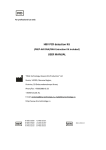
Tilt Transducer - Type TT420 User Manual Issue 1.0 Controlled Systems Limited Ryder Close, Swadlincote, Derbyshire. DE11 9EU. England TEL: +44 (0)1283 216231 / FAX: +44 (0)1283 552937 / [email protected] TT420 Tilt Transducer 1/8 March 2014 – Issue 1.0 Table of Contents 1 Features ..........................................................................................3 2 Description ......................................................................................3 2.1 4-20mA Signal Outputs........................................................................... 3 2.2 RS485 Communications Port ................................................................. 4 3 Connections ....................................................................................5 4 Installation .......................................................................................6 5 Mechanical Details ..........................................................................7 6 Environmental .................................................................................7 7 Conformity ......................................................................................8 8 Maintenance ...................................................................................8 9 Certification .....................................................................................8 TT420 Tilt Transducer 2/8 March 2014 – Issue 1.0 1 2 Features Rugged stainless steel housing suitable for machine mounting in harsh environments (e.g. mining) Solid-state, no moving parts for high reliability +/- 90deg range 4-20mA signal outputs (16-bit DAC) with HART (future option) RS485 communications - Modbus RTU Operating Temperature: -40ºC to +70ºC Hardware Low Pass Filter (LPF) on sensor signals 16-bit ADC with 64x oversampling and software digital filtering algorithms Intrinsically Safe ‘ia’ Group I Mining M1 and Group IIB ATEX and IECEx Certified. Description The unit is constructed from high quality stainless steel and is fully encapsulated providing a rugged solution for all angular and tilt measurements. The connections are made by a multi-pin plug and socket arrangement on the end of the unit. This allows easy replacement for example if the unit is due for re-calibration. 2.1 4-20mA Signal Outputs The two 4-20mA analogue output signals provide the user with signals corresponding to the pitch and roll of the unit. The first output is HART capable (future software upgrade required), this will allow all the information presented on the RS485 port to be also available to a suitably connected HART interface. The factory default range supplied is +/- 90°, this corresponds to the 4-20mA levels as shown below – 4mA = - 90° 12mA = 0° 20mA = TT420 Tilt Transducer + 90° 3/8 March 2014 – Issue 1.0 The transducer will drive full scale 20mA into a load resistance of approx. 330R maximum. Typically the load would be 100R or 250R in many applications. If the transducer detects that it is unable to drive the correct current into the load – for example the loop resistance is greater than 330R or the 12V supply voltage is too low, then it reacts by alternating the 4-20mA output between 0mA and the intended level at 1second intervals. This is to alert the monitoring equipment that the level it is reading is not correct and avoids undetected inaccuracies. Once the loop resistance/supply voltage returns to within range then the signal returns to the normal correct steady value. 2.2 RS485 Communications Port The RS485 port provides an alternative or in addition to the 4-20mA signals. More information is available using this method, e.g.- scaled angular readings and diagnostic status bits. Some of the information is only used during factory calibration so will not all be useful to the end user. Note: The user should not attempt to write to any registers, these are for factory calibration only. They are locked to prevent unintentional writes. The Modbus register mapping is shown below TT420 MODBUS Communications map REV 2 Input Registers Read 30001 TT420 Heartbeat 30002 Status 30003 Anlg 1 Reading (Voltage) f 30005 Anlg 2 Reading (Voltage) f 30007 Anlg 3 Reading (Voltage) f 30009 Anlg 4 Reading (Voltage) f 30011 Anlg 5 Reading (Voltage) f 30013 Anlg 6 Reading (Voltage) f 30015 Anlg 1 Engineering Reading g f 30017 Anlg 2 Engineering Reading g f 30019 Anlg 3 Engineering Reading g f 30021 Anlg 4 Engineering Reading V f 30023 Anlg 5 Engineering Reading °C f 30025 Anlg 6 Engineering Reading V f 30027 Pitch (F/B) f 30029 Roll (L/R) f 30031 DAC Output 1 16bit = 0-20mA 30032 DAC Output 2 16bit = 0-20mA 30033 Pitch (F/B) x 100 30034 Roll (L/R) x 100 30035 Serial Number Year 30036 Serial Number 30037 Software Version 30038 Hardware Version 30039 Main Thread Heartbeat 30040 DAC Thread Heartbeat 30041 ADC Thread Heartbeat 30042 Comms Thread Heartbeat 30050 Raw Pitch(F/B) f 30052 Raw Roll(L/R) f TT420 Tilt Transducer Status Meanings (bits) bit 0 Config Valid Pitch Config Valid bit 1 bit 2 Roll Config Valid bit 3 Pitch invalid bit 4 Roll invalid bit 5 DAC 1 Fault bit 6 DAC 2 Fault bit 7 DACs Not Calibrated bit 8 bit 9 bit 10 bit 11 bit 12 bit 13 bit 14 bit 15 DAC Calibation mode f 40001 DAC 1 Output if enabled 40002 DAC 2 Output if enabled Modbus Float Holding Registers Read/Write 4000-20000 = 4-20mA 4000-20000 = 4-20mA 40050 40051 40052 40053 Unlock Code 1 Unlock Code 2 Unlock Code 3 TT420 Mode A55A 5AA5 DDDD 0 Normal, 1 Config, 255 Reset to Bootloader 40100 40101 40102 40103 40104 40105 40106 40107 40108 40109 40110 40111 40112 40113 40114 40115 40116 40117 40118 40119 Unlock Code 1 Unlock Code 2 Unlock Code 3 Serial Number Year Serial Number Hardware Version Modbus Address Modbus Baudrate Pitch Range Min Pitch Range Max Roll Range Min Roll Range Max DAC 1 Sensor Source DAC 2 Sensor Source DAC1 4mA Setting DAC1 12mA Setting DAC1 20mA Setting DAC2 4mA Setting DAC2 12mA Setting DAC2 20mA Setting A55A 5AA5 CCCC 1-254 0 115k2, 1 57k6, 2 38k4, 3 19k2, 4 9k6, 5 4k8 0 0mA, 1 Pitch, 2 Roll, 3 Temp, 4 485 D1, 5 485 D2 0 0mA, 1 Pitch, 2 Roll, 3 Temp, 4 485 D1, 5 485 D2 40200 40201 40202 40203 40204 40205 …. Unlock Code 1 Unlock Code 2 Unlock Code 3 Pitch Cal Number of Samples Pitch Cal S1 Actual Pitch Cal S1 Expected …. A55A 5AA5 AAAA 40300 40301 40302 40303 40304 40305 …. Unlock Code 1 Unlock Code 2 Unlock Code 3 Roll Cal Number of Samples Roll Cal S1 Actual Roll Cal S1 Expected …. A55A 5AA5 BBBB 4/8 March 2014 – Issue 1.0 3 Connections Fischer 9-Pin Connector (Part number S105A101-130 + cable clamp E31 105.2/9.2+ B) Core Fischer Colour Pair Black 5a Blue 4a Violet 5b Red 4b Green Function Pin 1 0V SUPPLY I/P 2 12V SUPPLY I/P 2a 3 0V SIGNAL COMMON Yellow 2b 4 White 1a 5 4-20mA O/P #1 (PITCH) 0V SIGNAL COMMON Brown 1b 6 4-20mA O/P #2 (ROLL) 7 0V (cable screen) Braid Grey 3a 8 RS485 - B Pink 3b 9 RS485 - A Note: The cable core colours are shown for reference if using a CSL supplied cable assembly utilising Lutze 117320 cable. TT420 Tilt Transducer 5/8 March 2014 – Issue 1.0 4 Installation The connections to the units 9-Pin Fischer connector, as shown above, should be made using good quality cable having >= 0.5mm insulation thickness between cores. Alternatively a ready-made cable assembly can be purchased - shown on the front page picture. The operating parameters must not exceed those detailed on the certificate. This apparatus must only be installed or replaced by a competent person who must ensure that existing I.S. segregation is maintained. The operators should be trained in the safe use of the equipment, such that operational hazards arising from misuse are avoided. The unit should be mounted observing the following orientation – +90° 0° -90° PITCH 0° +90° -90° TT420 Tilt Transducer ROLL 6/8 March 2014 – Issue 1.0 5 Mechanical Details All values are approximate. 6 Length 130mm Width 53mm Depth 40mm Weight 1.1Kg. Environmental Operating Temperature -40°C…+70°C Storage Temperature 0°C…+40°C Humidity 0…95% RH, non-condensing Ingress Protection IP66 TT420 Tilt Transducer 7/8 March 2014 – Issue 1.0 7 Conformity The TT420 Tilt Transducer is designed and manufactured to be compliant with the following Standards and Directives: EN 60079-0:2012, IEC 60079-0:2011 Ed 6 Electrical apparatus For explosive gas atmospheres: General requirements EN 60079-11:2012, IEC 60079-11:2011 Ed 6 Explosive atmospheres: Intrinsic safety “i” EN 60079-26:2006 Explosive atmospheres: Equipment protection level (EPL) Ga 8 89/336/EEC EMC Directive 73/23/EEC Low Voltage Directive Maintenance No routine maintenance is required. Any damage that may affect the safe operation of the unit, e.g. - damaged enclosure, connector or cable, should be corrected by replacing the unit or cable, there are no user serviceable parts inside and to maintain dust seals the units should not be disassembled by the end user. Note: The complete assembly is encapsulated. 9 Certification Ex ia I Ma, Category M1 Ex ia IIB T4 Ga Ex ia IIIC T135°C Da CML 13ATEX2011 IECEx CML 14.**** (pending) See certificates for further information. TT420 Tilt Transducer 8/8 March 2014 – Issue 1.0