1
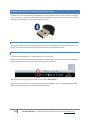
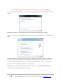
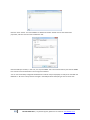
M-Tech Automotive / NODIZ Limited NODIZ Pro™ User Manual PROTOTYPE/TEST UNIT MANUAL REV A CONTENTS Introduction ....................................................................................................................................................... 2 The NODIZ Pro™ Unit and Connections............................................................................................................... 3 Buttons and Indicator LEDs ............................................................................................................................. 3 Indicator LEDs ............................................................................................................................................. 3 BUTTONS .................................................................................................................................................... 3 Connections .......................................................................................................Error! Bookmark not defined. Hardware Installation ......................................................................................................................................... 5 Moutning of the NODIZ Pro™ Unit .................................................................................................................. 5 Trigger Wheel and Crank sensor installation ................................................................................................... 5 Coil Pack Installation ....................................................................................................................................... 5 General Wiring ............................................................................................................................................... 5 Wiring of the Throttle Position Sensor ............................................................................................................ 6 Optional Systems Wiring ................................................................................................................................. 7 Tachometer Output .................................................................................................................................... 7 COOLANT and AIR TEMPERATURE SENSORS .................................................. Error! Bookmark not defined. MAP SENSOR PLUMBING ...............................................................................Error! Bookmark not defined. AUXILLARY OUTPUTS (SHIFT LIGHTS, VVT, FAN, FUEL PUMP ETC) ............................................................... 7 Setup/Calibrating ............................................................................................................................................... 8 Base Timing/IGNITION OFFSET ANGLE Setup .................................................................................................. 8 Throttle Position Sensor (TPS) Calibration ....................................................................................................... 9 Connecting To Your PC/Laptop with Bluetooth™ .............................................................................................. 10 Setting up the USB Dongle ........................................................................................................................ 10 NODIZ Pro™ Tuning Suite.................................................................................................................................. 13 1 M-Tech NODIZ Pro™ | For further support, please visit us online at www.NODIZ.co.uk INTRODUCTION The NODIZ Pro™ is a state of the art microprocessor controlled digital stand-alone, fully mappable ignition controller for four cylinder spark ignition engines. It can be used either to replace older distributor based ignition systems for more modern coil packs, or even to allow the running of carburettors on more modern engines which do not feature a distributor drive. It features in-built coil drivers, so no need for EDIS or any external modules. It is truly 3D, giving an advance angle based not only on engine speed but also on engine load, which can be derived from either its optional in-built Manifold Absolute Pressure Sensor (MAP), or using a potentiometer type Throttle Position Sensor (TPS). The NODIZ Pro™ is incredibly simple to install, and will always arrive pre-loaded with a suitable base-map of your choice. With only seven connections to make, you can be up and running in a matter of minutes, and if you opted for a pre-loomed system, this can be even quicker. To use the NODIZ Pro™, you will need, at a minimum, the following components. All can be obtained from our website (www.NODIZ.co.uk) or sourced locally. Trigger Wheel - In the case of modern engines this will probably already either be cast into the flywheel, or fitted to the front pulley. Note that direct support for many OEM trigger wheels is being added. (Currently 36-1, and 60-2 are fully supported, see the website for others.) Crank Sensor – A standard 2 Wire VR type crank sensor for reading the Trigger Wheel. Coil Pack – Standard Wasted Spark ‘dumb’ coil pack. Ford style ones work best and universal ones are available from us. If you are using a TPS based NODIZ Pro™, then you will also need a 3-wire TPS sensor fitted to your throttle linkage/carburettor(s). In addition to the above most direct and simple installation, the NODIZ Pro™ also features the following (some features require the use of the NODIZ Pro™ Power Suite Windows software to set them up, or we can carry out a setup at time of ordering for you): 16 Load by 16 Speed Sites, with full 3D interpolation and user definable Speeds/Loads. User settable RPM Soft and Hard Cut Rev Limiters. Coolant based ignition adjustment map (To add advance to cold engines, etc.). Intake Air Temperature ignition adjustment map, to allow timing retarding based on intake temperature to reduce pinking on very high intake temperatures. Cranking based advance angle to help start high compression engines. A programmable Shift Light output. 5v Tachometer Output. A programmable output based on either RPM (i.e. V-TEC control), coolant temperature (i.e. Fan Control), Intake temperature (i.e. Water Injection control), or Manifold Pressure (i.e. for 5th Injector systems). Bluetooth™ Communications built in, with USB PC/Laptop dongle supplied. There is a full video guide on our website, at www.NODIZ.co.uk, which runs through the installation and setup procedure for this powerful stand-alone ignition controller. 2 M-Tech NODIZ Pro™ | For further support, please visit us online at www.NODIZ.co.uk THE NODIZ PRO™ UNIT AND CONNECTIONS BUTTONS AND INDICATOR LEDS INDICATOR LEDS The RED LED indicates that the unit is powered up. If this light does not illuminate when power is supplied to the NODIZ Pro™, or flashes slowly, refer to the troubleshooting section. The BLUE and GREEN LED indicate a variety of information. In normal running use, they signify the firing of Coil A and B, hence they will alternately flash at a speed that relates to the engine speed. They also indicate entry into different setup modes, and these are detailed in the relevant section. BUTTONS The two push buttons on the NODIZ Pro™ are used to set different modes, adjust base offset and also to factory reset the unit. Holding down the button(s) shown during turning the power on, results in the actions shown in the table below being taken: BUTTON A (Outermost) HELD OFF HELD BUTTON B (Innermost) OFF HELD HELD RESULT Offset Angle Calibration Mode/Fixed Ignition firing at 0* TDC Throttle Position Sensor Calibration Mode Factory reset of the NODIZ Pro™. The buttons have different functions in different modes, and the relevant sections in this manual detail their functions in those modes. 3 M-Tech NODIZ Pro™ | For further support, please visit us online at www.NODIZ.co.uk MAIN LOOM CONNECTION S The NODIZ Pro™ features an automotive standard connector for various connections to be made to the engine and other systems. The main connector, is a 14-way black MOLEX style plug. Pin Number 1 2 3 4 5 6 7 8 9 10 11 12 13 14 Function Crank Sensor (It does not matter which way Crank Sensor round these are connected…) NOT YET IMPLEMENTED Tachometer Output (For 5V digital tachometers) NOT YET IMPLEMENTED NOT YET IMPLEMENTED 12V Main Power (To be switched on by the key) TPS (Throttle Sensor) Reference (5V) TPS (Throttle Sensor) Signal GROUND Programmable Output (500mA Switched Earth) GROUND COIL A –ve Feed (Switched Earth) COIL B –ve Feed (Switched Earth) There is also (on the MAP based NODIZ Pro™) a 4mm vacuum fitting which should be connected to the intake manifold to read its pressure. 4 M-Tech NODIZ Pro™ | For further support, please visit us online at www.NODIZ.co.uk HARDWARE INSTALLATION MOUNTING OF THE NODIZ PRO™ UNIT The NODIZ Pro™ unit is supplied in a sealed aluminium case, and has been tested and shown to operate fully submerged in water, strapped to a hot exhaust manifold and even dragged along the road, however, it is best practice to mount the unit away from areas where it could become wet or overheated, as this will ensure longevity. Most users generally mount the unit using sticky back Velcro pads to allow for easy removal (an added immobilisation feature when leaving the car unattended at shows), though a hard mounting bracketing kit can be supplied if required. The case itself does not need to be earthed, and so can be mounted to painted/non-metallic surfaces. TRIGGER WHEEL AND CRANK SENSOR INSTALLATION COIL PACK INSTALLATION The coil pack to be used is a standard OEM Ford Four Cylinder Coil-pack, as fitted to most Fords from 1994 Fiesta/Escort models though to current Ford Focuses/Mondeo models. If you are unsure of the type, please see our website, www.NODIZ.co.uk. GENERAL WIRING Although the NODIZ Pro™ has been designed using the very latest noise-immune practices and components, it is still important to follow these basic, commonly accepted wiring principles when wiring/routing the wiring loom: Keep the NODIZ Pro™ unit and crank sensor wiring as far from the HT system as sensibly possible (HT leads, Coil Pack and Plugs). Around 500mm (rarely as much is needed in practice) spacing is more than adequate. Ensure no wires run where chafing or heat are likely to damage them. If passing through a bulkhead be sure to use grommets where required. Ensure no wires are under stress. Try not to run the crank sensor wiring in the same conduit as the coil output wires, alternator wiring, or any other sources of electrical noise. Always use suitable shielded cable for crank sensor wiring, and be sure to earth the outer shield to the chassis. Ensure any ground/earth wires are of a strong connection to the chassis. Ensure that the main power wire to the NODIZ Pro™ does not ‘switch off’ during cranking, as can be the case on some classic cars. It must remain live (Around 8-14v) when both cranking AND running. Always solder and heat-shrink wiring where possible. Bullet connectors and Scotch-Locks are not the best practices to ensure longevity, and are often sources of reliability issues. 5 M-Tech NODIZ Pro™ | For further support, please visit us online at www.NODIZ.co.uk WIRING OF THE THROTTLE POSITION SENSOR The throttle position sensor is used to tell the NODIZ Pro™ the current throttle position. It should be of a three wire variety (as in most OEM cases and also if supplied by us.) First, we must determine what the connections are on your TPS. As a guide, generally, the middle connection is the TPS signal, but follow this simple guide below to ensure you make the right connections: 1) Set your multi-meter to measure resistance in the order of 1 or 2 Mega-Ohms. 2) Connect it to two of the connections on the TPS sensor 3) Sweep the throttle slowly from CLOSED to OPEN, whilst watching the resistance reading. If the reading on the multi-meter stays the same, then you have found the GROUND and TPS VOLTAGE REFERENCE wires, although we do not yet know which is which. If the reading starts HIGH, and then REDUCES, then you are connected with the TPS SIGNAL wire and TPS VOLTAGE REFERNECE wires, although we do not yet know which is which. If the reading starts LOW and INCREASES then you are connected with the TPS SIGNAL and the GROUND connection, although we do not yet know which is which. By changing the pins that you are taking the readings from and going back to step three, you will eventually be able to mark each wire with GROUND, TPS SIGNAL and TPS VOLTAGE REFERENCE. Once you have done this, follow the wiring diagram below for connection to the NODIZ Pro™. 6 M-Tech NODIZ Pro™ | For further support, please visit us online at www.NODIZ.co.uk OPTIONAL SYSTEMS WIRING The NODIZ Pro™ features several optional systems, which can be used if you wish, however most require setup during mapping, or setting at the time of order by your supplier, although with the software you will be able to adjust every setting on the unit. TACHOMETER OUTPUT The NODIZ Pro™ features a 5v 50% Duty tachometer output that can be used to drive modern or aftermarket tachometers. For traditional 12v tachometers, a diode pack will be needed to drive the tachometer, which is available from our website. COOLANT AND INTAKE TEMPERATURE SENSORS NOT YET IMPLEMENTED IN VERSION 1. MAP SENSOR PLUMBING On NODIZ Pro™ units with the MAP sensor upgrade, a 4mm bulkhead fitting is provided on the unit to facilitate connection of a 4mm silicone hose which should then be connected to the intake manifold to read to the manifold pressure. This must be connected to the manifold between the throttle and intake face of the engine, usually the same location as the brake servo take off can be used. AUXILLARY OUTPUTS (SHIFT LIGHTS, VVT, FAN, FUEL PUMP ETC) NOT YET IMPLEMENTED IN VERSION 1. 7 M-Tech NODIZ Pro™ | For further support, please visit us online at www.NODIZ.co.uk BASIC SETUP/CALIBRATING There are two methods of setup. The easiest method is without the use of a PC/Laptop, and uses the unit itself to setup base timing (in effect ‘twisting’ the distributor), as well as calibrate the throttle position sensor (if used). The second method uses the PC/Laptop to allow full calibration of the ignition map, as well as a host of other features. We suggest that the first method is used to get the engine running, and then optimisation can be carried out afterwards using a PC/Laptop. BASE TIMING/IGNITION OFFSET ANGLE SETUP The NODIZ Pro™ enables you to accurately set the 0* point by offering a mode called fixed firing. In this mode, the system will always fire its ignition coil on channel A at what it believes to be 0*, or TDC. Use this mode to check the position of Crank Sensor, trigger disc missing tooth angle, and correct coil wiring. You will also be able to adjust the ‘OFFSET ANGLE’ using the buttons from within this mode, to ensure that, for example, a commanded advance of 15* BTDC really is 15* BTDC and not out by any amount. IT IS RECCOMENDED YOU DISCONNECT THE ENGINES FUEL SUPPLY OR INJECTORS TO PREVENT THE ENGINE FIRING DURING THIS INTITIAL SETUP PHASE. CARBURETTERS WILL USUALLY CONTAIN A SMALL AMOUNT OF FUEL IN FLOAT CHAMBERS SO THE ENGINE MAY ‘POP’ ON REMAINING FUEL, BUT THIS IS NORMAL. ENTERING BASE TIMING SETUP MODE To enter this mode, with the NODIZ Pro™ all wired, and the ignition switched off, HOLD DOWN Button A (Outermost). Next, turn on the ignition. The RED Power LED will illuminate, and the GREEN LED and the BLUE LED will be OFF. Release Button A. The GREEN LED will flash four times. You are now in Base Timing/Offset Setup Mode. CHECKING/ADJUSTING BASE TIMING First you must establish the TDC position of your engine. You can either use the factory timing marks (although not always accurate!) or manually turn the engine to TDC, and mark the bottom pulley and a fixed reference point on the block, such that it can be seen with a timing light. Next, using a timing-light, reading from cylinder one’s HT lead, verify the position of the firing point in relation to the engines TDC mark by cranking the engine. If you see no flashes from the timing gun, refer to the trouble shooting section. Next, (and it is best to do this whilst cranking the engine) press Button A (OUTTERMOST) to INCREASE the Base Offset Angle, or Button B (INNERMOST) to DECREASE it. You will notice that the mark you made on the bottom pulley will move closer, or further away from the TDC mark as the system changes its base offset angle. The objective is to get the timing light to flash, showing that the engine is firing when your TDC marks align, i.e. firing at ZERO degrees, or TDC. You will only be able to adjust the offset by 20 degrees either way, hence why it is important to ensure that your fitment and relationship of the trigger wheel and sensor are as accurate as possible such that the missing gap passes the sensor when the engine is turned to 90* BTDC. Once you are happy with the firing at TDC, simply turn off the ignition, and the Base Offset/Base Timing position will be permanently stored in the NODIZ Pro™. 8 M-Tech NODIZ Pro™ | For further support, please visit us online at www.NODIZ.co.uk THROTTLE POSITION SENSOR (TPS) CALIBRATION When ordering, if specified, the NODIZ Pro™ offers the ability to use a Throttle Position Sensor, or TPS, as a means of determining load. This is more common for use on Individual Throttle Body/Twin Carbs or Motorbike Carbs fuelled engines, as reading a MAP sensor value from these types of engines requires extra piping and take-offs needing to be fitted. ENTERING TPS CALIBRATION MODE To enter Throttle Position Sensor calibration mode, with the ignition switched off, hold down BUTTON B (the innermost button), and turn the ignition on whilst keeping this button depressed. The NODIZ will flash the BLUE and ORANGE LEDs together to show to that TPS calibration has been entered. You are are now in TPS calibration mode. The engine will not run in this mode. CALIBRATING THE TPS Whilst in TPS Calibration Mode, simply sweep the throttle from open to closed several times. The NODIZ Pro™ will constantly update its memory such that the upper and lower results are stored, and also, you will notice that the LED flashes at different rates to indicate throttle position. You can now check that the throttle wiring and TPS sensors are working correctly by slowly opening and closing the throttle, and noticing that the LEDs flash faster with higher throttle openings, and more slowly as you near closed throttle. If this is not the case, refer to the relevant trouble shooting section. If you make a mistake at any point, return to the section above on entering TPS Calibration mode, and follow the instructions again. Once you are happy with the TPS calibration, to exit this mode, simply switch off the ignition, and switch back on, with no buttons depressed. 9 M-Tech NODIZ Pro™ | For further support, please visit us online at www.NODIZ.co.uk CONNECTING TO YOUR PC/LAPTOP WITH BLUETOOTH™ The NODIZ Pro™ is equipped with an in-built Bluetooth™ module which means for testing, setup and mapping you can use either a laptop (many of which feature in-built Bluetooth™ connectivity) or a PC with the supplied Bluetooth™ USB dongle. The range is approximately 20 meters. SETTING UP THE USB DONGLE The following is a guide for Windows 7 based PCs. Other versions of Windows are supported, but at the time writing have not been tested, though the setup process will be fundamentally the same. STEP ONE First install the USB Dongle into a unused USB port on your PC/Laptop. Windows should automatically detect the USB dongle, and will install it. After this is completed, the following logo should appear in the lower right corner of the screen on the task bar: Now right click the image and from the pop-up menu select ‘Add a Device’. Note that you will only need to do this the first time you link the NODIZ to your PC with the Bluetooth dongle. After successful connection, this will from then on be automatic. 10 M-Tech NODIZ Pro™ | For further support, please visit us online at www.NODIZ.co.uk Be sure to have the NODIZ Pro™ unit powered and in range of the PC/Laptop at this point! The following dialog will be presented, and after a short time the empty white box will show a device named ‘Linvor’: Double-click this new icon, and ‘Connecting to device’ will be shown at the bottom of the dialog. After a brief moment, the following dialog will appear, be sure to click the middle option ‘Enter device pairing code’: An input box will appear asking for the pairing code. Enter ‘1234’ in the box (just the numbers, 1234) and hit OK. After a moment a ‘Device Ready to Use’ notification should appear in the lower right of the screen, you may even catch which Com Port number it is assigned (usually COM10 or COM11, but varies with each PC.) Next we must confirm what port number the unit has been given. Right click the little Bluetooth™ icon on the task bar again, and this time click ‘Show Bluetooth Devices’. If all has gone well so far, the following should be shown: 11 M-Tech NODIZ Pro™ | For further support, please visit us online at www.NODIZ.co.uk Note the ‘linvor’ device. This is the NODIZ Pro™ Bluetooth module. Double click to show the devices properties, and then click the second ‘Hardware’ tab: Note the COM port number, in this case, it is on port COM10. This is the communications port that the NODIZ Pro™ will be communicated with in the Tuning Suite software. You can now successfully configured the Bluetooth™ module and your PC/Laptop is ready to be used with the NODIZ Pro™. Be sure to always have the Dongle in the USB port when attempting to connect to the unit. 12 M-Tech NODIZ Pro™ | For further support, please visit us online at www.NODIZ.co.uk NODIZ PRO™ TUNING SUITE The tuning suite is designed to run on Windows XP/Vista/7 32 or 64 bit versions. It allows full mapping abilities as well as a host of data-logging features, advanced module setup and features control. The latest version is always available on the www.nodiz.co.uk website, as well as links to the latest versions of the Microsoft .NET framework which it requires to run. 13 M-Tech NODIZ Pro™ | For further support, please visit us online at www.NODIZ.co.uk