1
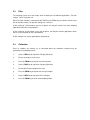
HR1000 USER MANUAL
Version 2.6
Table Of Contents
1.0
2.0
Installation
1.1
1.1.1
Power Supply
AC Adapter
1.2
Loadcell Connections
1.3
LCD Contrast
1.4
Indicator Mounting
User Operation
2.1
3.0
Auto Zero Tracking
Calibration Overview
3.1
Variables
3.2
Gain
3.3
Filter
3.4
Calibration
1.0
Installation
The HR1000 is a precision electronic instrument and requires careful handling. It should be ideally
installed in a dry atmosphere away from direct sunlight.
The HR1000 and the loadcell cable should be kept well away from any source of electrical noise.
The loadcell cable should be kept as short as possible.
1.1
Power Supply
The HR1000 may be powered by the supplied adapter :
Other battery options are available, consult Advanced Micropower Ltd for futher details.
1.1.1
AC Adapter
Important Note :
The AC adapter is NOT waterproof, and
must NOT be used in a damp environment.
The AC adapter supplied provides 9 Volts at 300mA current. The end of the lead has two soldered
wires. The polarity of the wires is as follows :
Black lead only
Black lead with white tracer colour
-
Negative (left)
Positive
It must be ensured the power is connected with the correct polarity.
The wire goes through the appropriate cable gland and directly to a two way terminal block on the
printed circuit board.
There are NO user serviceable parts contained within the unit. Live parts are enclosed. In the
event of a failure return the unit to Advanced Micropower Ltd.
1.2
Loadcell Connections
The loadcell connection is as follows : (from left)
1.
2.
3.
4.
5.
6.
Loadcell positive signal
Loadcell negative signal
Loadcell positive sense
Loadcell positive exitation
Loadcell negative sense
Loadcell negative exitation
-
SIG+
SIGSEN+
EX+
SENEX-
The loadcell wire goes through the appropriate cable gland and
should go a single turn through the supplied ferrite core and then to the four way terminal block on
the printed circuit board.
Note: Simply passing through the ferrite is NOT correct.
Figure 1 above shows the loadcell connector :
1.3
LCD Contrast
The contrast on the LCD display can be adjusted by varying a trimmer pot on the printed circuit
board.
The location of the (black) trimmer pot is shown on figure 1 above.
The contrast may need to be adjusted for optimum viewing angle depending on the HR1000
mounting position.
1.4
Indicator Mounting
Two brackets allow the HR1000 to be table or wall mounted.
2.0
User Operation
The front panel keys are described below:
ON
This key turns the power to the HR1000 ON
OFF
This key turns the power to the HR1000 OFF
TARE
This key sets the tare deduction.
If tare is required the desired weight should be
on the scale and the tare key pressed.
placed
Once tare is not required the tare key should be
with the scale empty.
pressed
ZERO
This key sets the scale to zero.
If the zero point has drifted pressing the zero key
will
correct it.
The zero key is only operational within a small
of the calibrated zero point.
range
Zero will not be operational if a weight is on the scale and the
will show Zero Err.
display
2.1
Auto Zero Tracking
The HR1000 will monitor the slow drift of the zero point and automatically track and compensate
for this error. This feature will only be operational when the displayed weight is close to zero and
the weight remains stable for ten seconds.
3.0
Calibration Overview
To enter calibration mode the following sequence is necessary :
1. Hold in both the ZERO and TARE keys during power on.
The display will show :
Cal 1
2. Press and release the TARE key within 3 seconds
The display will now show :
Cal 2
4. Press and release the ZERO key within 3 seconds
Calibration mode will now be entered and the display will
typically show :
F00030.0
Any incorrect keypress OR delay in pressing the keys will cause the indicator to enter normal
weighing mode.
Once in calibrate mode the first character will be flashing, The TARE key will step the display on
to the next parameter.
If the TARE key is pushed a number of times the following typical displays will appear :
F00030.0
S00005.0
R000.010
Gain
4
B1778023
Z1463453
S2437325
Filt
8
Exit Cal
The following is a brief description of the displays :
F00030.0
case 30.0 Kg
This is the Full scale value which the HR1000 can display. In
this
S00005.0
This is the Span value to be used for calibration. In this case
5.0 Kg.
R000.010
This is the desired Resolution of the indicator. In this case
10 grams.
Gain 4
This is the Gain of the HR1000 loadcell amplifier.
B1778023
This is the current value (in bits) of the A to D converter, and
dynamically changes when the scale load is varied.
Z1463453
This is the A to D converter bits which currently represent the
calibrated zero point.
S2437325
This is the A to D converter bits which currently represent the
calibrated span point.
Filt
8
Exit Cal
This is the filter setting of the system.
This gives the user an option to exit the calibration mode.
3.1
Variables
The FULL SCALE, SPAN and RESOLUTION variables can be set as desired in the following way
:
1.
Use the TARE key when the first character is flashing to select the
parameter to be modified.
desired
2.
Press the ZERO key to go into edit mode for the selected parameter.
digit to be modified will be underlined
.
At this stage the
3.
While in edit mode press the TARE key to increment the underlined
digit.
4.
When the digit is correct press the ZERO key to select the next digit
to be modified.
5.
The ZERO key may be pushed until the first digit flashes again. The
ZERO key will
now re-enter the edit mode while the TARE key will
step on to the next parameter.
3.2
Gain
The A to D converter has a front end amplifier which has a programmable gain which may be set
by the user.
When the Gain variable is selected with the TARE key the ZERO key can now be used to select
the desired gain. The possible gains are 1,2,4,8.
For optimum performance the gain should be set as high as possible, but care should be taken
that the full load signal does not cause the A to D bits to saturate. This may be checked by
looking at the bits display (Bxxxxxxx).
For most common loadcells with a sensitivity of 1 or 2 mV/V a gain of 4 or 8 is usual.
3.3
Filter
The weighing system can have various levels of filtering to suit different applications. The filter
settings can be set by the user.
When the Filter variable is selected with the TARE key the ZERO key can now be used to select
the desired filter setting. The possible settings are 1,2,4,8,16.
A filter setting of 1 will provide a very fast response, and may be used for fast check weighing
applications with static scale platforms.
A filter setting of 16 will provide a very slow response, and may be used for applications where
there is a lot of vibration on the scale platform.
A filter setting of 2 or 4 gives good general performance.
3.4
Calibration
Once all variables are correctly set as described above the calibration sequence may be
performed in the following manner :
1.
Use the TARE key to step to the Z display (Zero bits)
2.
Ensure no weight is on the scale
3.
Press the ZERO key to register the new zero point
4.
Use the TARE key to step to the S display (Span bits)
5.
Put the desired span weight on the scale
6.
Press the ZERO key to register the new span weight
7.
Use the TARE key to step to the Exit Cal display
8.
Press the ZERO key to return to the weighing mode