1
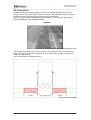
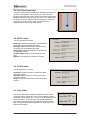
____________________________ User Manual ____________________________ FORSBERG SERVICES LTD 1 WATERVIEW, WHITE CROSS LANCASTER, LA1 4XS UNITED KINGDOM TEL: +44 (0) 1524 383320 FAX: +44 (0) 1524 848374 F064990-09-0001 v2.01 Forsberg Services Ltd. OptoNAV User Manual 1. Propriety Notice Information in this document is subject to change without notice and does not represent a commitment on the part of Forsberg Services Limited. The system described in this document is furnished under a non-disclosure agreement. The document may be used or copied only in accordance with that agreement. It is against the wishes of Forsberg Services Limited to copy the document on any medium except as specifically allowed in the non-disclosure agreement. No part of this document may be reproduced or transmitted in any form or by any means, electronic or mechanical, including photocopying or recording, for any purpose without the express written permission of Forsberg Services Limited. The information within this document is understood to be true and correct at the time of publication. 2007 Forsberg Services Limited. All rights reserved. 2 Forsberg Services Ltd. OptoNAV User Manual 2. Contents 1. 2. 3. 4. Propriety Notice ............................................................................................................... 2 Contents............................................................................................................................ 3 Figures .............................................................................................................................. 4 Introduction ...................................................................................................................... 5 4.1. OptoNAV......................................................................................................................... 5 4.2. System Overview ............................................................................................................ 5 4.3. System Details ................................................................................................................ 5 4.4. Camera Feed .................................................................................................................. 6 5. OptoNAV Software ........................................................................................................... 7 5.1. Start-up ........................................................................................................................... 7 5.2. Layout ............................................................................................................................. 7 5.3. Layout Guides ................................................................................................................ 8 5.4. RTG Visual Indication ..................................................................................................... 9 5.5. RTG Position .................................................................................................................. 9 5.6. GPS Position .................................................................................................................. 9 5.7. Lane Limits ..................................................................................................................... 9 5.8. Direction Indicator ......................................................................................................... 10 5.9. Status Bar ..................................................................................................................... 10 5.10. Status Messages ........................................................................................................ 10 5.11. Traffic Light Status ...................................................................................................... 11 5.12. System Shutdown ....................................................................................................... 11 6. Admin Mode.................................................................................................................... 12 6.1. Overview ....................................................................................................................... 12 6.2. Auto - Survey ................................................................................................................ 12 6.3. Define Lines .................................................................................................................. 12 6.4. Auto-Record.................................................................................................................. 12 7. Support ........................................................................................................................... 13 7.1. Contact Details ............................................................................................................. 13 3 Forsberg Services Ltd. OptoNAV User Manual 3. Figures Figure 1 OptoNAV System Diagram .......................................................................................... 5 Figure 2 Camera Feed with drive line ........................................................................................ 6 Figure 3 Camera Visibility .......................................................................................................... 6 Figure 4 RTG Visual Indication .................................................................................................. 9 Figure 5 RTG Position ............................................................................................................... 9 Figure 6 GPS Position ............................................................................................................... 9 Figure 7 Lane Limits .................................................................................................................. 9 Figure 8 Direction Indicator ...................................................................................................... 10 Figure 9 Status Bar .................................................................................................................. 10 4 Forsberg Services Ltd. OptoNAV User Manual 4. Introduction 4.1. OptoNAV The OptoNAV system assists the RTG operator by providing a visual camera reference of the RTG in relation to the driveline. Two cameras mounted each side of the vehicle continually monitor the direction, angle and accuracy of the RTG to the driveline by image processing techniques. The Northing and Easting position derived from these images are then compared with given system parameters. Any RTG deviation from these parameters will be visually displayed to the Operator via the traffic light display screen in the cabin. By interfacing the OptoNAV system with the onboard RTG “Assisted Steering Module” it can provide a seamless reliable fallback in the event of poor GPS data. Therefore OptoNAV will still give the Operator a continuous visual of driveline accuracy or obstructions. 4.2. System Overview The OptoNAV system is a combination of hardware and software that provides the user with the ability to navigate using machine vision. The diagram below shows the OptoNAV system design. Figure 1 OptoNAV System Diagram 4.3. System Details The OptoNAV system consists of the following components. • • • • • • • OptoNAV ICE Box Industrial PC with OptoNAV software pre-installed OptoNAV ICE Box Industrial PC Mains Adapter 2x High Performance Colour CCD Camera with lens Combined Video and Power Cable Phono to BNC Adapter (pre-fitted to cable) Mains adapter for above camera OptoNAV CD containing PC software and manual 5 Forsberg Services Ltd. OptoNAV User Manual 4.4. Camera Feed OptoNAV utilises two cameras positioned to face both possible drive directions. The live images from the camera provide the means to determine the heading of the RTG as well as providing a means to observe the area in front and behind the RTG. Figure 2, below, shows an example image received by one of the cameras. Both camera feeds are displayed on the OptoNAV interface. Figure 2 Camera Feed with drive line The cameras are positioned on one leg of the RTG and provide an area of view as shown below. It should be noted that the cameras do not provide visual coverage closer than 1.77 meters from the RTG leg. This is represented in the diagram below. Figure 3 Camera Visibility 6 Forsberg Services Ltd. OptoNAV User Manual 5. OptoNAV Software 5.1. Start-up OptoNAV will start automatically when the RTG system is turned on. 5.2. Layout The OptoNAV software starts automatically on system power up. The OptoNAV software consists of a simple user friendly interface that requires minimal interaction. The display shows: • Live feeds from camera one and camera two • Visual representation of the RTG position and heading • RTG position data • GPS position data • Lane limits • RTG position quality • Heading information • Status bar Note: On start-up of the OptoNAV software, an initial picture is taken from the camera, no live video will be displayed at this point. 7 Forsberg Services Ltd. OptoNAV User Manual 5.3. Layout Guides The following images show the OptoNAV user interface and provide a breakdown for each section. 8 Forsberg Services Ltd. OptoNAV User Manual 5.4. RTG Visual Indication The RTG visual indication displays the heading and position of the RTG in comparison with the drive line. The drive line is shown in green and the RTG is shown by the blue circle with its heading displayed by the blue line. If there is any movement by the RTG to the left or right this will be displayed by movement of the blue circle to the left or right. The lane limits are displayed by the amber and red shadings. Figure 4 RTG Visual Indication 5.5. RTG Position The RTG position box shows: Northings: Northing RTG position calculated from the image and the available GPS data. Eastings: Easting RTG position calculated from the image and the available GPS data. Along Track: Distance the RTG has moved from its originating position Camera Height: Height of the camera from the floor. Std Dev: The quality of the position in meters. Figure 5 RTG Position 5.6. GPS Position The GPS position box shows: Northings: Northing position received from GPS receiver in meters. Eastings: Eastings position received from GPS receiver in meters. Height: Height from sea-level received from GPS receiver. Figure 6 GPS Position 5.7. Lane Limits The Lane Limits section provides a guideline for the cranes movement from the drive line. They are provided as a safety mechanism. As a default this is set as +/- 10 centimeters for the lower limit and +/- 15 for the upper limit. If this threshold is reached an alert will display on the status bar and the traffic light. The lane limits can be adjusted by an expert user in the administrator options. Figure 7 Lane Limits 9 Forsberg Services Ltd. OptoNAV User Manual 5.8. Direction Indicator The direction indicator will provide information on the RTG’s heading and it’s offset. The heading data is displayed in degrees relative to the drive line. The Left | Right data is provided in meters from the drive line. Figure 8 Direction Indicator 5.9. Status Bar The Status bar displays the the operational status of the OptoNAV software . this will also prompt the user when input is required and provide hints for operation. The messages are displayed in the tabl below. Figure 9 Status Bar 5.10. Status Messages Message Left click on furthest visible point on drive line 1 Left click on nearest visible point on drive line 1 Left click on furthest visible point on drive line 2 Left click on nearest visible point on drive line 2 Both Lines Defined Course Good! Heading off course!! Check Position of Drive Line!!! RECORDING!!! BAD CAMERA 1 DATA BAD CAMERA 2 DATA BAD CAMERA 1 & 2 DATA 10 Meaning Using the mouse left click on the furthest point of drive line 1 (The drive line located in the Camera 1 view field) Using the mouse left click on the nearest point of drive line 1 (The drive line located in the Camera 1 view field) Using the mouse left click on the furthest point of drive line 2 (The drive line located in the Camera 2 view field) Using the mouse left click on the nearest point of drive line 2 (The drive line located in the Camera 2 view field) A drive line has been defined in both camera views RTG is within the lower lane limits RTG has exceeded the lower lane limit but is still within the upper lane limit RTG has exceeded the upper lane limit Auto Record function has been activated and is recording data Poor image conditions or insufficient data for camera 1 to calculate RTG navigation Poor image conditions or insufficient data for camera 2 to calculate RTG navigation Poor image conditions or insufficient data for both cameras to calculate RTG navigation Forsberg Services Ltd. OptoNAV User Manual 5.11. Traffic Light Status OptoNAV uses a traffic light system to prompt the system status displaying either a green, amber or red light. The status is displayed along the bottom of the user interface. Green Light A green light will be displayed if the drive line is visible in both measure boxes and the RTG is travelling on good course. Amber Light When the amber light is displayed the drive line is only visible in one measure box. There are several reasons for this: • Drive Line has become worn or is obscured • RTG has exceeded the lower lane limits and is moving off course Red Light The Red light is displayed if the drive line is not visible in either measure boxes. • Drive Lines have become worn or both are obscured • RTG has exceeded the upper lane limits and is off course 5.12. System Shutdown The OptoNAV system will shut down automatically on RTG power down. 11 Forsberg Services Ltd. OptoNAV User Manual 6. Admin Mode 6.1. Overview OptoNAV has a built in administrator mode which provides the ability to automatically survey sections of the port, define the lane limits and auto-record data for problem finding. These options are located at the top of the screen under ‘File’ and ‘Settings’ and require and expert user for access. Information on what is available through the admin mode is detailed below. Please see ‘F064990-09-0004 OptoNAV Set-up and Installation Guide’ for full instructions and detailed use. 6.2. Auto - Survey The auto-survey function is used to teach the software to recognise designated areas of the port. When encountering a drive-line that has not been previously surveyed or one with known errors the auto-survey function will store the drive line with the required information to the library for use. 6.3. Define Lines The lane limits provide a guideline for the RTG movement and is used as a safety mechanism to alert the driver when they are moving off course. The lines can be altered to provide different tolerance levels for RTG movement. 6.4. Auto-Record Auto Record is used to aid the development of the OptoNAV software. When enabled the system will capture the data received in normal use or it can be left running unattended. Auto record will prompt the OptoNAV software will capture an image from both cameras and save them with the name specified as the current date and time. At the same time current GPS position (Northings, Eastings & Height) is recorded to a log file. Data can be opened and interrogated at a later date. 12 Forsberg Services Ltd. OptoNAV User Manual 7. Support 7.1. Contact Details OptoNAV was developed by Forsberg Services Ltd. please contact for all support enquiries. Forsberg Services Ltd. 1b Waterview, White Cross Lancaster, LA1 4XS UNITED KINGDOM E-mail: [email protected] Tel: +44-1524-383320 Fax: +44-1524-382939 13