1
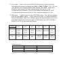
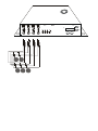
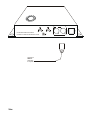
USER MANUAL for
Neo-Neon SRC-171 “Color Master DMX” LED controller
INTRODUCTION
SRC-171 is an intelligent power source with multi
functions console. It can also to be applied on
dimming and on/off switch. The voltage SRC-171
supply is DC24V, three outputs to control R, G & B,
and the currency is 3.5A each, total output is 10A.
This controller can be used independently or
controlled by DMX-512 controller.
SPECIFICATION
Weight: 1.6kg
Size:
360*210*65
Input voltage: 220VAC---240VAC
Output voltage: 24VDC
Max. output power consumption: 360W
Signal output connector:
DMX connector: 3-pin connector
Out shell: Q235
OPERATING INSTRUCTIONS
1)Pushing the MODE button to select: DMX,
Manual, Roll or Auto modes.
A) Manual Mode: In Manual mode, press the
FUNCTION button after entering this mode,
the LED menu display will show
correspondingly R000, G000 or B000. R
stands for red output, G for green and B for
blue. Press UP or DOWN to adjust the output
figure from 000 to 255.
B) Roll mode: In Roll mode, press the
FUNCTION button after entering this mode,
the displayer will display correspondingly ro-1
or SP01 or FS00. “RO”, “SP” and “FS” stand
for roll mode, roll speed and strobe speed
respectively. Press UP and Down to adjust
respectively the ROLL mode between 1 to 4,
ROLL speed between 01 to FL, corresponding
time between 0.12S to 6S, strobe speed
between 00 to 99, corresponding speed
between 25Hz to 0.5Hz.
C) Auto mode: In Auto mode, press FUNCTION button after entering this mode,
the displayer will display correspondingly SP01 or FS00 OR FD00. “SP”, “FS” and
“FD” stand for color-changing speed, strobe speed & step speed. Press UP &
DOWN to adjust respectively color-changing speed between 01 to 100,
corresponding time between 0.12s to 6s, and strobe speed between 00 to 99,
corresponding speed between 25Hz to 0.5Hz, step speed between 0 to 10s.
D) DMX Mode: In DMX mode, press the FUNCTION button. The LED menu display
will show either d001 or d-P1.
“d001” stand for the SRC-171 initiative address to
receive DMX signals. Press UP or DOWN to adjust the address between 001 to 512;
enter d-P1, denotes the mode of reception of DMX signal, press UP or DOWN to
choose P1 or P2, the work mode as following
Channel
Mode
CH 1
CH 2
CH 3
internal
Output
Strobe
program
Control
Speed
Green
Blue
CH 4
CH 5
CH 6
No function
Step Speed
Output
Strobe
Step
Control
Speed
Speed
Select
P1
No
function
(128)
P2
Red
Cable length limits:
Percentage of full load
Output Distance (Meters)
Output Cable diameter
0-100%
1m-20m
>/= 1.5mm
2
0-40%
21m-40m
>/= 1.5mm
2
41-100%
21m-40m
>/= 2.5mm
2
24V 12A MAX. 24V 5A MAX.
24V 5A MAX.
24V 5A MAX.
DMX IN
DMX OUT
MANUAL
UP
DMX
ROLL
COMMON
BLUE
GREEN
RED
DOWN
BLUE GREEN RED POWER
MODE
FUNCTION
AUTO
DMX IN
DMX OUT
DMX IN
DMX OUT
AC100~240V
47~63Hz
NO USER SERVICEABLE PARTS INSIDE.
DISCONNECT POWER BEFORE REMOVING COVERS.
Connect to
DMX512
Controller
if required
Size
FUSE: 10A?
TROUBLESHOOTI NG
1. The screen does not light.
Check the power connection.
Check the socket
2. The buttons do not work
Check whether all the springs of the buttons are still elastic to bounce back.
Check whether a clear sound is produced by pressing the button.
3. The screen is flashing after connected to the power.
Check if there is any button spring loses its elasticity to bounce back.
If all the methods above do not work, please contact the tech support.