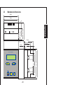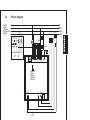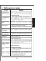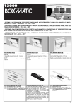
1
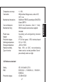
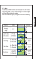
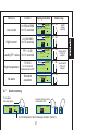
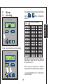
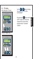
WARNING
COMAR declines
all liability for any
damage to
people or
property caused
by unsuitable or
incorrect use of
its products.
Comar reserves
The right to
change product
specifications
wiThout prior
notice.
ATTENTION
COMAR décline
toute
responsabilité
pour éventuels
dommages à
personnes et
matériels causés
par une utilisation
impropre ou par
un emploi des
produits
incorrect. Comar
se reserve le droit
de modifier sans
preavis les
caracteristiques
tecniques des
materiels.
ACHTUNG
COMAR
lehntjede
Verantwortung
für eventuelle
Schäden an
Personen oder
Sachen
infolge von
unsachgemäßem
Gebrauch der
Control ab.
Änderungen
vorbehalten.
ATENCION
La COMAR
declina toda
responsabilidad
por eventuales
danos a
personas o
cosas
producidos por
el uso
inadecuado o
equivocado de
sus productos.
Puede ser
modificado sin
preaviso.
COMAR CONDENSATORI S.p.A.
Via del Lavoro, 80 - CRESPELLANO (Bologna)
Tel. + 39 51 733.383 - Fax + 39 51 733.620
P.O. Box 134 - 40011 ANZOLA EMILIA (Bologna)
MU - 03.10.Mmm REV.NO - 05-2000 - 1000
ATTENZIONE
La COMAR
declina ogni
responsabilità
per eventuali
danni a persone
o cose originati
da uso improprio
o da errato
impiego dei
propri prodotti.
Soggetto a
modifiche senza
preavviso.
USER MANUAL
QSR6
User manual
page 21
Index
1
1.1
1.2
1.3
1.4
1.5
2
2.1
2.2
2.3
2.4
2.5
3
3.1
3.2
3.3
3.4
3.5
4
4.1
Instruction
Introduction
Operator safety
Instructions for proper
installation
Cleaning
Warranty
General
Unit description
Mechanical fixing
Working situation
Power of controlled
banks
Number of steps
Technical features
General features
Reference standard
Mechanical dimensions
Pinout diagram
How to choose the C.T.
Functions
Powering on
p.22
p.22
p.23
p.23
p.23
p.24
p.24
p.24
p.24
p.25
p.25
p.25
p.26
p.26
p.27
p.28
p.29
p.30
p.32
p.32
21
4.2
4.3
4.4
4.5
4.6
4.7
5
5.1
5.2
6
Key functions
Automatic
Manual
Manual insertion
of the banks
Alarms
Alarm memory
Set-up
C/K setting
P.F. setting
Working troubles
and solution
p.32
p.33
p.34
p.35
p.36
p.37
p.38
p.38
p.39
p.40
1
Instruction
1.1
Introduction
Before connecting the regulator to the mains, read the instructions in this
handbook, they provide important indications about the safety, use and
maintenance. Take carefully this handbook for any information.
This regulator has been manufactured and tested in accordance with
international standard, it leaves the factory in perfect safety conditions. In
order to mantain these condition and to ensure safe operation, the user must
comply with the instructions and remarks given in this manual. After removing
the packaging check that the regulator has not been damaged during transport.
In case of doubt, do not attempt to fix or use the regulator. If the equipment
has falled down or has been violently shaken during transport, it could suffer
internal damages which may be dangerous.
After checking that regulator cannot be safely used, it must be placed out of
order and not used before checking of experienced personnel. Causes that
bring to put the regulator out of order are the presence of external damages,
missed functioning, unproper stocking or transport conditions. Technical
Assistance on the regulator must be performed exclusively by COMAR
personnel.
22
1.2
Operator safety
Before to perform any maintenance, the regulator must be disconnected from
any power supply source, wait 5 minutes before start any action. During
maintenance it is necessary to follow standard safety procedures. Do not
touch any printed circuit board for any reason.
This regulator will be assigned only to the use for which it has been
specifically made. Each other use has to be considered improper and
therefore dangerous.
1.3
Instruction for proper installation
Before connect the equipment, check the data plate: this has to be in
conformity with the electrical network (the plate is located on the back
of the P.F. Regulator). The regulator is not provided with protection fuse
on the power supply, it has to be protected externally by the user. Being
the regulator designed for permanent operation (CEI EN 61010-1), the
supply have to be interrupted by automatic switch, which has to be placed
close the regulator for easy intervention.
For the correct functioning of the equipment, the limit of voltage, current
and temperature, imposed by the CEI and IEC standard must never be
exceeded. The equipment has to be protected from athmospheric
conditions.
1.4
Cleaning
After disconnecting the instrument from the power supply, clean the
external surface of the plastic box using a soft cloth dipped in water only.
Never use abrasive or solvent. Never wet the connection terminals.
23
1.5
Warranty
Comar Condensatori S.p.A. guarantees its own products for twelve months
from purchase date.
The warranty covers the faults of materials and manufacture and it has to be
understand for goods ex-works. Before the equipment works, all instructions,
present on this handbook, have to be meticulously followed. Breakdowns
caused from improper use and/or not conformity to enclosed instructions and
faults caused from tampering by unqualified technicians aren’t covered.
The misuse of any of the previous points will erode the right of warranty.
2
General
2.1
Unit description
QSR is an automatic microprocessor regulator which operates the switching
on and off of the capacitors steps which are necessary to reach and to
maintain the required power factor value. The QSR operate an RMS measure
which allows correct operation and display even in presence of harmonics.
The central microprocessor unit controls all settings and parameters.
2.2
Mechanical fixing
The regulator should be mounted in a cutout (drilling template 92x92mm.)
using the special fixings supplied.
24
2.3
Worning situation
The regulator works according to binary logic sequence; the switching on
and off of capacitors banks always start from the first bank.
2.4
Power of controlled banks
For correct operation of the automatic bank, the power ratio per bank should
be:
a.
equal to each other
(1-1-1-1-1-1-1-1)
b.
double of the previous bank
(1-2-4-8-16-32)
c.
equal or double of the previous bank
(1-1-2-2-4-4)
2.5
Number of steps
Is determined by the power combination which has been
capacitors bank:
Examples:
6 banks in the sequence 1-1-1-1-1-1
6 banks in the sequence 1-1-2-4-4-4
6 banks in the sequence 1-2-4-8-16-32
used on single
make 6 steps
make 16 steps
make 63 steps
Note. A too high number of steps as a too high power of first step , produce
an high number of switching operation that reduce the life of the equipment.
When the first step is too high in power hunting may occur which again would
produce excessive wear and reduced life of the components.
Normally 8-16 regulating steps is the best solution to adopt
25
3
Technical features
3.1
General features
Rated supply voltage
Rated consumption
Rated supply current
Current circuit consumption
Rated frequency
Controlled banks
Output relays
Max current relays common
Switching steps delay
Alarm delay
P.F. setting
Operating range
Digital monitoring
Measurement monitoring
Accuracy
Multivoltage 380÷415V a.c. ± 10%
400V -10% / +5% continuous operation
3 VA
By means of CT secondary side
st
5A max., 1 class - 5VA (Imin. = 500mA)
2VA
50Hz or 60Hz autoset
6
5A 250 Va.c. resistive load
5A at 40°C resistive load
25" (5" on request)
10"÷ 1"
0,90 lag ÷ 0,90 lead
Power Factor 0,20 ÷1,00 lag / lead
Alphanumeric 2x16 characters
LCD display
P.F. 0,20÷1,00 lag / lead
On the P.F. regulation range ± 2 f.s.
at +25°C and 2,5A.
26
Temperature accuracy
Connection
Mechanical dimensions
Cut out dimension
Mechanical fixing
Plastic case
Weight
Protection degree
Working temperature
Storage temperature
Relative humidity
Type of service
+/- 10%
With terminal fixing screws, cable of 2,5
2
mm c.s.a.
96x96 mm FRONT (according to DIN43700)
60mm DEPTH
92x92 mm (tolerance -0mm /+ 1mm).
With the special accessories supplied
included
Insulating self-extinguishing material
0,5 Kg
IP 54 front panel - IP20 terminal board
0°C to + 50°C
-20°C to +60°C
Max. 90% at 20°C noncondensing
Indoor service, no dusty condition. Do not
place directly under sun light.
3.2 Reference standard
Safety
EMC
Protection degree
IEC 1010 440V CAT III
EN50082-1, EN50082-2, EN50011,
EN55022
CEI-EN 605.29
27
Mechanical dimensions
96mm
60mm
38,2mm
18,3mm
3,5mm
91mm
60mm
38,2mm
3,5mm
18,3mm
4" Setup
28
91mm
96mm
68mm
Power Factor Regulator
Made in Europe
3.3
3.4
Pinout diagram
Carichi
Loads
Charges
Verbraucher
Cargas
CT../5
220V
L
0V
1A
T1 T2 T3 T4 T5 T6
C1....6
X1X2 1 2 3 4 5 6 C
Allarme
Alarm
Alarme
Störung
Alarma
A A
V
29
V
Max 4A
K
3.5
How to choose the CURRENT TRANSFORMER (C.T.)
Use a Current Transformer (C.T.) with 5A at secondary circuit and primary
equal or slightly higher than the maximum absorbed by the loads. The C.T.
must be chosen in such a way to obtain a good current signal in the
secondary circuit. Current values between 0.5 and 5Amps are suitable to
obtain good working conditions of the regulator.
The C.T. must be good quality (first class) and with power equal or higher
to 5VA. If the C.T. has been mounted far from the equipment, it needs to
add the normal demanded the power consumed from2the cables of connection
(normaly 0.2VA per meter of bifilar lines with 2.5mm section) and the power
dissipated by others possible tools connected in the circuit.
The equations, used to calculate the real losses, are the sequents:
R = 2 x x L/S2
(Ω)
Total resistance of amperometric circuit
P=(R+0.08) x I (VA)
Losses of amperometrical circuit
‘ ’ is the electrical resistivity ( 0.018 for the copper )
‘L’ is the length of amperometric circuit (mt)
‘S’ is the across section of cables at the secondary of TA
‘I’’ is Imax. at the secondary of C.T.
‘0.08’ are the internal resistance of P.F. regulator
When single-phase inductive loads are connected (unbalanced three-phase
system), place C.T. on the phase where Power Factor is lower and/or where
higher current value is absorbed.
2
The cables at the secondary of C.T. have to be of 2,5mm section.
The C.T. connection must not to be protected with fuses or interruped by
switch.
30
The C.T. has to be connected to the line, upstream the load and the P.F.
Regulator: the C.T., can then measure the current demanded by the load,
inductive and capacitive. Possible capacitors for fixed P.F.Regulation will
be mounted downstream of the C.T., as they aren’t used and dimensioned
for the P.F. Regulation of transformers that feed the load.
It’s important to check that the phase, where the C.T. is connected, is the
same that will be connected to terminals of the main switch, inside the
equipment, signed with the letter “L1”.
Before doing any work on the C.T. circuit, be sure that the C.T. is shortcircuited, otherwise dangerous voltages can rise, add bringing to breakdown
the C.T.
P.F. correcting two or more lines (transformers in parallel), you need to use
two or more C.T (.../5) of which the secondary circuits will be supplied a
add transformer with 5Amps at secondary: connect the current transformers
at the same phase.
If two or more C.T. ‘s are used with an additional transformer, the value of
the primary current is the sum of each C.T. Example: n°3 C.T. ‘s 500/5 =
n°1 C.T. 1500/5.
Connecting two or more cables (for load and P.F.Regulator) on the same
terminal - phase “L1” - from the general main switch, It needs to pass
through the hole of the C.T. all the derived cables.
Note. QSR regulators are able to detect automatically the current phasing
of the CT. It is not necessary to ensure correct polarity connections as with
other Power Factor Regulators.
31
4
P.F. Value
“+” P.F. Lag
“-” P.F. Lead
Functions
4.1
Powering on
When power is switched on, an internal
self test routine has been performed.
The display shows the installed s/w
release.
Banks
disconnection
CAP
Spinning when
working
Banks
+0,93 PF/
connenction
123---
Output
ON
4.2
IND
Output
OFF
Key function
Power Factor Regulator
enable change from
The key
“Automatic” to “Manual” (light is on).
When pressed for 4 seconds it
enable to enter the set-up page and
confirm setting
SELF TEST - v1.9
used in “Manual”
Keys
enable switch-on and off the output.
Used in “SET-UP” enable setting of
the value.
Used in “Automatic” enable
visualization and reset of “Alarm
After start-up process, the regulator is memory”.
working in ”Automatic” operation.
Made in Europe
4" Setup
32
4.3
Automatic
Power Factor Regulator
Power Factor Regulator
+0,93 PF/
12345- IND
+0,97 PF/
---45-
4" Setup
Made in Europe
Made in Europe
4" Setup
Fig. 1
Fig. 3
Power Factor Regulator
-0,99 PF/
CAP --345-
Made in Europe
4" Setup
Fig.1: inductive loads connected
(motors, transformers, decharge
lamps, etc.).
“IND” indication on and regulator
that inserts the required outputs.
Fig. 2: capacitive loads connected.
“CAP” indication on and regulator
that disconnects the exceeding
outputs.
Fig. 3: P.F. value setted is achieved
when Cap and IND indications are
off. Output are not changing.
Fig. 2
33
4.4
Manual
Power Factor Regulator
Power Factor Regulator
+0,93 PF/ MANUAL
123---
-0,99 PF/ MANUAL
CAP --3456
Fig.1 The key is lit (on)
Made in Europe
4" Setup
Made in Europe
4" Setup
Fig.3 Output switch off
Power Factor Regulator
+0,99 PF/ MANUAL
123456 IND
Manual working visualize balanced
load (IND and CAP indication off).
Switch on/off are made only after
the proper response time (25
seconds standard).
Made in Europe
4" Setup
Fig.2 Output insertion (switch on)
34
Manual insertion of the banks
Power Factor Regulator
Power Factor Regulator
+0,93 PF/ MANUAL
1-----
+0,93 PF/ MANUAL
------
4" Setup
Made in Europe
4" Setup
Fig.1 Bank insertion
Fig.3 Reset memory
In Automatic operation the “stored”
output are always on.
The remaining output are working
in Automatic, the stored output
can be disconnected exclusively
when operation shows in fig.3
occurs (key on, key pressed) or
switching off the power supply
Power Factor Regulator
+0,93 PF/ MANUAL
1----Blinking
Made in Europe
4" Setup
Fig.2 Entering memory
Made in Europe
4.5
35
4.6 Alarms
The QSR has a normally closed NC alarm contact (rated 5 A 250 V resistive
load). It will be possible to give an external alarm signal. This contact is signed
with X1 and X2 in the base of the regulator.
When alarm condition disappears, the regulator will reset itself automatically.
Reference
Condition
Display indications
No supply
voltage
V=0
Low P.F. value
in the network
PF = IND
for 15 minuts
0,35 PF/
ALARM
123456
Low voltage
V < 340Vac RMS
for 10 seconds
High voltage
V > 450Vac RMS
for 10 seconds
Zero Current
A<50mA RMS
for 10 seconds
36
Alarm relay
X1
X2
X1
X2
Blinking
ALARM
0,95 PF/ MIN V
123---
X1
X2
Quick switch
off for all
outputs
Blinking
ALARM
0,95 PF/ MAX V
------
X1
X2
Quick switch
off for all
outputs
Blinking
X1
ALARM
-,-- PF/
A = 0
------
X2
Quick switch
off for all
outputs
Blinking
Condition
Display indication
X1
X2
Low current
A<350mA RMS
for 10 seconds
ALARM
0,35 PF/ MIN A
123--Bliking
ALARM
0,95 PF/ MAX A
123---
X1
X2
Hight current
A>5,5A RMS
for 10 seconds
PF< ± 0,20
for 10 seconds
Bliking
ALARM
-,-- PF/
CAP
------
X1
X2
Leading P.F. value
Bliking
ALARM
0,95 PF/
TEMP
------
X1
X2
X1
X2
Reference
T°>50°C
Hight temperature
for 10 seconds
Hysteresis level 5°C
No alarm
Standard
operation
4.7
Bliking
0,95 PF/
123---
Alarm relay
Alarm memory
To visualize
last alarm press
To erase memory press
at the same time
MEMORY = MAX V
123---
MEMORY = VOID
123---
A dot indicates an alarm message stored in memory
37
Inhibit
output
insertion
Quick switch
off for all
outputs
Quick switch
off for all
outputs
5
Set-up
The suggested value to set is given on the table.
5.1
C/K setting
Use the
selection.
or
buttons to change the
Power Factor Regulator
T.A. - C.T.
30/5
50/5
60/5
80/5
100/5
150/5
200/5
250/5
300/5
400/5
500/5
600/5
800/5
1000/5
1200/5
1500/
2000/5
2500/5
3000/5
4000/5
Made in Europe
4" Setup
Puss 4 seconds for aut. functioning
Power Factor Regulator
3 C/K
Power 1st bank (kvar)
C/K
+0,93 PF/ MANUAL
123---
SETUP
+0,97 PF
5
5
3
3
3
3
2
2
2
2
2
1
1
1
1
1
1
1
1
1
1
6
5
4
4
3
3
3
2
2
2
2
2
1
1
1
1
1
1
1
1
1
10 12,5 20
5
5
5
5
5
3
4
5
3
3
5
3
3
3
3
3
3
2
3
3
2
2
3
2
2
3
2
2
2
2
2
2
1
2
2
1
1
2
1
1
2
1
1
1
1
1
1
1
1
1
1
1
1
25
5
4
3
3
3
3
3
2
2
2
2
1
1
1
1
40
5
5
4
3
3
3
3
3
2
2
2
2
2
1
50
5
5
4
3
3
3
3
3
2
2
2
2
2
When the CT secondary current signal is
lower than 2 amps, the C/K value should
be increased by 0,1.
Blinking
When using the regulator on 220Vac
networks the C/K values should be doubled.
4" Setup
Made in Europe
“-” means installation of C.T. with primary
value too small.
38
5.2 P.F. setting
After setting the C/K value
or
buttons to change
Use the
the selection. A P.F. of 0,95 is
recommended.
Power Factor Regulator
3 C/K
SETUP
+0,97 PF
button, the C/K
By pressing the
and P.F. values which have been
selected will be saved and the
regulator works in “Automatic”
condition.
Blinking
Made in Europe
4" Setup
Press the “Manual” key
Power Factor Regulator
3 C/K
SETUP
+0,97 PF
Blinking
Made in Europe
4" Setup
39
6
Working tuonbles and solution.
TROUBLE
Soluzione
All banks on with a low
The CT is connected upstream the load but not of capacitors.
inductive load on the network Connect the CT as shown in the connection diagram ( § 3.4).
a) The C/K value is not correct.
Continous switching on and
Check in the table "C/K VALUES" for the right value ( § 5.1).
off of first bank (hunting
b) The power of the first bank is too high for the selected PF requirements.
phenomena)
Reduce the first bank power according to paragraphs 2.4 and 2.5.
Increase the selected PF value ( § 5.2).
Displayed PF values not
CT installed in the wrong phase: connect to phase L1 ( § 3.4).
correct
a) Possible stand-by condition: at least one capacitor bank on.
Check the PF value of the network on the display.
IND and CAP leds off
b) Possible MANUAL working condition: choose the AUTOMATIC operation.
IND led ON and no insertion
of capacitor banks
Minimun current alarm. Current lower than 500mA (see § 4.6).
CAP led is ON without
capacitor banks working
CT installed in the wrong phase: connect to phase L1 (see § 3.4).
a) Alarm condition of least one value: see chapter (§ 4.6).
b) Check supply voltage is correct.
a) Check if supply voltage is present.
Display off, regulator not working b) Check if supply voltage is equal to the rated voltage of the regulator.
Blinking display
Display on, banks inserted
signalling, but capacitors
not working
a) Check if supply voltage is equal to the rated voltage of the regulator.
b) Check the “0Vac” connection on contactors.
c) Check if “220Vac” has been connected on "C" terminal.
d) Check contactor functioning.
Displayed “ ALARM CAP” on a) Possible capacitive load condition.
b) CT installed in the wrong phase: connect to phase L1 (§ 4.6).
display
c) P.F. lower than 0,20 IND or CAP.
a) Zero current signal: check the C.T. and its connection and ensure the
minimum secondary current level is least 10mAmps (§ 3.4).
Displayed “-.--” on display
b) C.T. connected on the supply cable of the PFC equipment.
Connect according the connection diagram ( § 3.4).
IF PROBLEMS PERSIST AFTER ALL ABOVE MENTIONED SOLUTIONS SWITCH OFF THE REGULATOR FOR AT LEAST 20
SECS AND THEN SWITCH ON AGAIN. IF THE PROBLEM IS STILL PRESENT PLEASE CALL OUR TECHNICAL DEPARTMENT.
40