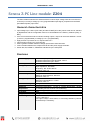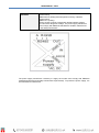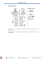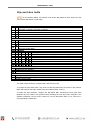
1
USER MANUAL Z204 This document is property of SENECA srl. Duplication and reproduction of its are forbidden (though partial), if not authorized. Contents of present documentation refers to products and technologies described in it. Though we strive for reach perfection continually, all technical data contained in this document may be modified or added due to technical and commercial needs; it’s impossible eliminate mismatches and discordances completely. Contents of present documentation is anyhow subjected to periodical revision. If you have any questions don’t hesitate to contact our structure or to write us to e-mail addresses as above mentioned. MI002972 Page 1 USER MANUAL – Z204 Seneca Z-PC Line module: Z204 The Z204 module measures the alternate and/or continue input voltage value and converts it to a current (0..20 mA) or voltage (0..10 V) programmable output signal, proportional to the RMS (Root Mean Square) input value. General characteristics Input voltage up to 1200 V (DC scale) and 850 V RMS (AC scale), which scale can be selected by Dipswitches and the configuration have to be downloaded on the Z204 by software (Easy, ZNET). If the screw terminals mode is selected «analog output», output can be turned between: current (0..20 mA, programmable) or voltage (0..10 V, programmable). High precision: input class is 0.5, outputs class is 0.1. Input frequency range: DC..30 Hz-300 Hz. 4000 V galvanic isolation between voltage input and the other terminals. 1500 V isolation between the output terminals and the power supply terminals. Power ON, fail, RS485 Tx, RS485 Rx: indications by the LED panel Features Power supply Consumption Voltage input Passband Current output Voltage output Thermal stability Response time Operating temperature LED signals Protection Weight, dimensions Overvoltage class 10..40 VDC (free polarity) or 19..28 VAC 50..60 Hz. Insulation toward the output terminals: 1500 V. Insulation toward the input: 4000 V <1 W at 24Vdc. Continue voltage 0..1200 Vdc; alternate voltage 0..850 Vac Input impedance: 800 kohm. Frequency: DC..30 Hz-300 Hz. Precision class: 0.5. At 1 kHz, error is 1.5% Range: 0..20 mA can be selected via DIP-switch. Maximum load resistance: 500 ohm. Precision class: 0.1 Range: 0..10 V can be selected via DIP-switch. Minimum load resistance: 1 kohm. Precision class: 0.1 100 ppm/K. For a stepped variation: 1 s from 10 to 90%. Operating temperature: -20..65 °C, storage temperature: -20..85 °C humidity 30..90% at 40°C non-condensing. Power ON (green), fail (yellow), Rx/Tx (red). IP20. 140 g, 100 x 112 x 17.5 mm. II, up to 600 Vrms; I, up to 1000 Vrms. For higher voltage / class values, an overvoltage limitation (external to the device) is necessary. 2 USER MANUAL – Z204 Conform to CE standards EN61000-6-4 (2007) (electromagnetic emission, industrial environment) EN61000-6-2 (2006) (electromagnetic immunity, industrial environment) EN61010-1 (safety) All the circuits must be provided with double isolation against circuits under dangerous voltage. The power supply transformer must comply with EN60742 standards for isolation transformers and safety transformers. The power supply transformer necessary to supply the module must comply with EN60742 (Isolated transformers and safety transformers requirements). To protect the power supply, it is recommended to install a fuse. 3 USER MANUAL – Z204 Connections Connect the pole «+» of voltage input, indifferently, to one of the screw terminals 7, 8, 9 (equipotentials). Connect the pole «-» of voltage input, indifferently, to one of the screw terminals 10, 11, 12 (equipotentials). 4 USER MANUAL – Z204 Dip-switches table In the following tables: box without circle means Dip-Switch=0 (OFF state); box with circle means Dip-Switch=1 (ON state). SW1 – INPUT SCALE 1 2 Meaning DC scale: 0..150 Vdc; AC scale: 0..100 Vac DC scale: 0..500 Vdc; AC scale: 0..350 Vac DC scale: 0..850 Vdc; AC scale: 0..600 Vac DC scale: 0..1200 Vdc; AC scale: 0..850 Vac SW2 - BAUDRATE 1 2 Meaning Baud-rate=9600 Baud Baud-rate=19200 Baud Baud-rate=38400 Baud Baud-rate=57600 Baud SW2 - ADDRESS 3 4 5 6 7 8 Meaning Address and Baud-Rate are acquired from memory(EEPROM) Address=1 Address=2 Address=3 Address=4 X X X X X X …………………… Address=63 SW3 - RS485 TERMINATOR 1 Meaning RS485 terminator disabled RS485 terminator enabled SW4 – OUTPUT MODALITY FOR SCREW TERMINALS 4 – 5 - 6 1 Meaning Analog output 0..10 V (voltage), 0..20 mA (current) RS 485 communication The Z204 module is factory configured with 1000 Vdc full scale. To change the input start scale / stop scale, set the Dip-Switch SW1 as shown in the previous table and configure the Z204 module using the software (Easy, Z-NET). To obtain the best resolution, configure the Dip-Switch SW1 selecting the lower input scale (between the four scales in the previous table) including the new stop scale. Example: if the software-configured new full scale is 680 Vdc, set the Dip-Switch SW1-1=»0», SW1-2=»1» (corresponding to 0-850 Vdc). 5 USER MANUAL – Z204 RS 485 register table Name Range MachineID FWREV Baudrate Scale outset and Interpretation of register Word R/W / R Id_Code (Module ID) / Word R Firmware Code / Word R/W Baud-rate for RS485 (baud-rate of module/node if parameters are configurated by memory modality): 0=4800; 1=9600; 2=19200; 3=38400; 4=57600; 5=115200; 6=1200; 7=2400 Word RW Input scale setting is bit[1,0]: 0=DC scale is 0-150Vdc, AC scale is 0-100 Vac 1=DC scale is 0-500Vdc, AC scale is 0-350 Vac 2=DC scale is 0-850Vdc, AC scale is 0-600 Vac 3=DC scale is 0-1200Vdc, AC scale is 0-850 Vac Delay Address and Parity Input start Input stop Out start scale (if current) Out stop scale (if current) Word R/W Output start scale, for current (in uA) Word R/W 6 Address 40001 0x4900 40002 40003 38400 40004 Bit [1,0]=3 Bit 2 = 0 Output signal type is bit[2]: 0=output is current; 1=output is voltage Word R/W Delay for RS485 (delay of communication response): from 0x0000=0 (no delay) to 0xFFFF=65535 Address: from 0x01=1 to MSB, LSB R/W 0xFF=255 Address for RS485 (address of module/node if parameters are configurated by memory modality) Parity for RS485: 0=there isn’t; 1=odd; 2=even Word R/W Input start scale (in V/10) Word R/W Input stop scale (in V/10) Output stop scale, for current (in uA) Default 40005 0 40006 1 Bit [15:8] 0 Bit [7:0] 40007 0 40008 10000 (=1000 V) 40009 4000 40010 20000 USER MANUAL – Z204 Out start scale (if voltage) Out stop scale (if voltage) Word R/W Output start scale, for voltage (in mV) Word R/W 0 V RMS Output stop scale, for voltage (in mV) Bit R Error status register, bit[0]=1: flash setting error; bit[1]=1: flash tarature error Word R V RMS float Input voltage RMS value, in V/10 (example: 10000=1000 VRMS) Floating point R Status 40011 40012 10000 40045 40046 40047(MSB) 40048(LSB) Input voltage VRMS value Command Word R/W 40050 To reset, write 0xC1A0 (49568 decimal) in this register LEDs for signalling In the front-side panel there are 4 LEDs and their state refers to important operating conditions of the module. LED PWR ERR LED status ON ON Meaning The module is power on Internal error RX ON TX ON Data are being received through the communication port Data are being transmitted through the communication port RS485 RS485 Easy-SETUP To configure the Seneca Z-PC Line modules, it is possible to use Easy-SETUP software, Freedownloadable from the www.seneca.it. 7