1
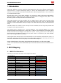
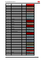
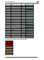
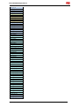
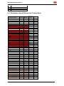
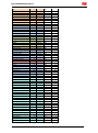
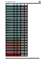
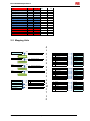
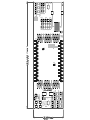
EDP-CM-PIM Adapter Board
dsPIC/PIC ‘Command Module’ – Adapter Board
EDP-CM-PIC-PIM User Manual
Version 1.04
10th June 2010
Electrocomponents plc
Page 1
EDP-CM-PIM Adapter Board
Contents
1.
Introduction
2.
2.1
2.2
2.3
2.4
2.5
MCU Mapping
3
MCU Pin Allocation ......................................................................... 3
Backplane Resources Used by the MCU ........................................ 5
Alphabetical Listing of MCU Pins .................................................... 7
Backplane Signal Names and Connections .................................... 9
Mapping Aids ................................................................................ 12
3.
Jumper Options
13
4.
Zero Ohm Links
19
5.
5.1
Software Support
22
dsPIC33FJ256MC710 ................................................................... 22
Electrocomponents plc
3
Page 2
EDP-CM-PIM Adapter Board
1. Introduction
The RS-EDP platform is a system, which has been designed to utilise many different manufacturers’
microprocessors. To support Microchip’s family of devices, the RS-EDP platform uses an adapter
board to connect between the RS-EDP baseboard and the Microchip PIM modules. This is referred to
as the EDP-CM-PIM module.
Microchip have most of their MCU’s available, pre-mounted on 80 pin and 100 pin PIM modules.
These are square in shape and use pin headers to connect down to a daughter board, which in the
Microchip system is usually some form of evaluation board.
The RS-EDP therefore uses these modules with an adapter board to gain access to the Microchip
portfolio of devices. One adapter board can be used with pretty much all of the Microchip PIM
modules, from the 8 bit PIC16Cxx family, through to the 16bit dsPIC family and the new 32bit PIC32
family.
The PIM modules are available to order directly from the RS website, and are separately listed in the
catalogue from the RS-EDP platform.
The adapter board is configured as a ‘Command Module’. The ‘Command Module’ in a system
dictates whether the whole system is a 3.3V one or a 5.0V one. The module has a link option which
decides which of the two voltages is used within the system. The Vcc_CM line is set to this level by
the link option on this adapter module. This Vcc_CM is used as a reference by the other modules,
such as the analogue module for example.
The daughter board remaps the I/O of the PIM module on to the backplane of the RS-EDP system. As
the RS-EDP system has a similar concept to the PIM module system from Microchip, you will find
most of the PIM modules will correctly map out to the RS-EDP backplane.
During the development of this board, several devices were chosen for trial fits to the RS-EDP
system. These included the dsPIC33FJ256MC710, the dsPIC33FJ256GP710 and the PIC32Mx4xxFxxxL
devices.
2. MCU Mapping
2.1 MCU Pin Allocation
The MCU pins have been allocated to the backplane as follows
dsPIC33FJ256MC710
Pin
1
2
3
4
5
6
7
8
9
10
11
12
13
14
Electrocomponents plc
Name
Comment
2 link options
2 link options
RG15
Vdd
PWM3H/RE5
PWM4L/RE6
PWM4H/RE7
AN16/T2CK/T7CK/RC1
AN17/T3CK/T6CK/RC2
AN18/T4CK/T9CK/RC3
AN19/T5CK/T8CK/RC4
SCK2/CN8/RG6
SDI2/CN9/RG7
SDO2/CN10/RG8
#MCLR
#SS2/CN11/RG9
Page 3
RS-EDP-BASE BOARD
Name
GPIO5_I2S_TX_WS
GPIO9_I2S_RX_WS
3.3V
MOTORP2H
AN8
AN9
GPIO2_MCI_DAT0
GPIO4_MCI_DAT1
GPIO6_MCI_DAT2
GPIO8_MCI_DAT3
SPI_SSC_CLK
SPI_SSC_MTSR_MOSI
SPI_SSC_MRST_MISO
#RESIN
SPI_SSC_#CS_NSS
EDP-CM-PIM Adapter Board
15
16
17
18
19
20
21
22
23
24
Vss
Vdd
TMS/RA0
AN20/#FLTA/INT1/RE8
AN21/#FLTB/INT2/RE9
AN5/QEB/CN7/RB5
AN4/QEA/CN6/RB4
AN3/INDX/CN5/RB3
AN2/#SS1/CN4/RB2
PGC3/EMUC3/AN1/CN3/RB1
25
PGD3/EMUD3/AN0/CN2/RB0
26
PGC1/EMUC1/AN6/OCFA/RB6
27
PGD1/EMUD1/AN7/RB7
28
29
30
31
32
33
34
35
36
37
38
39
40
41
42
43
44
45
46
47
48
49
50
Vref-/RA9
Vref+/RA10
Avdd
Avss
AN8/RB8
AN9/RB9
AN10/RB10
AN11/RB11
Vss
Vdd
TCK/RA1
#U2RTS/RF13
#U2CTS/RF12
AN12/RB12
AN13/RB13
AN14/RB14
AN15/OCFB/CN12/RB15
Vss
Vdd
IC7/#U1CTS/CN20/RD14
IC8/#U1RTS/CN21/RD15
U2RX/CN17/RF4
U2TX/CN18/RF5
SGND
3.3V
GPIO10_MCI_CLK
AN2
AN3
MOTORH0_ENC0
MOTORH1_ENC1
MOTORH2_ENC2
CNTRL_SPI_#CS_NSS
AN4
Local EMUC
AN5
Local EMUD
GPIO33_AD11
Local EMUC
GPIO34_AD2
Local EMUD
GPIO14_MCI_PWR
GPIO12_MCI_CMD
AN_REF
VAGND
AN6
AN7
AN0
AN1
SGND
3.3V
GPIO24_AD7
GPIO25_AD15
GPIO26_AD6
GPIO27_AD14
GPIO28_AD5
GPIO29_AD13
GPIO30_AD4
SGND
3.3V
EVM10_GPIO68_ASCO_CTS
EVG20_GPIO69_ASCO_RTS
ASC1_RX_TTL
ASC1_TX_TTL
51
52
53
54
55
56
57
58
59
60
61
62
63
64
65
66
67
68
69
70
U1TX/RF3
U1RX/RF2
SDO1/RF8
SDI1/RF7
SCK1/INT0/RF6
SDA/RG3
SCL1/RG2
SCL2/RA2
SDA2/RA3
TDI/RA4
TDO/RA5
Vdd
OSC1/CLKIN/RC12
OSC2/CLKO/RC15
Vss
INT3/RA14
INT4/RA15
IC1/RD8
IC2/RD9
IC3/RD10
ASC0_TX_TTL
ASC0_RX_TTL
CNTRL_SPI_MRST
CNTRL_SPI_MTSR
CNTRL_SPI_CLK
CNTRL_I2C_SDA
CNTRL_I2C_SCL
I2CGEN1_SCL
I2CGEN1_SDA
EVG7_GPIO54
EVG8_GPIO56
3.3V
Not applicable
Not applicable
SGND
EMG_TRAP
EVM6_GPIO49
EVM7_GPIO51
MOTOR_TCO_FB
EVM8_GPIO53
Electrocomponents plc
2 link options
2 link options
2 link options
2 link options
2 link options
2 link options
2 link options
2 link options
Page 4
EDP-CM-PIM Adapter Board
71
72
73
IC4/RD11
OC1/RD0
PGD2/EMUD2/SOSCI/CN/RC13
74
PGC2/EMUC2/SOSCO/T1CK/CN0/RC14
75
Vss
76
77
78
79
80
81
82
83
84
85
86
87
OC2/RD1
OC3/RD2
OC4/RD3
IC5/RD12
IC6/CN19/RD13
OC5/CN13/RD4
OC6/CN14/RD5
OC7/CN15/RD6
OC8/UPDN/CN16/RD7
Vddcore
Vdd
C1RX/RF0
88
C1TX/RF1
89
C2TX/RG1
90
C2RX/RG0
91
92
93
94
95
AN22/CN22/RA6
AN23/CN23/RA7
PWM1L/RE0
PWM1H/RE1
RG14
96
97
98
99
100
RG12
RG13
PWM2L/RE2
PWM2H/RE3
PWM3L/RE4
2 link options
2 link options
2 link options
2 link options
EVM9_GPIO55
MOTORPWM
GPIO0
local 32kHz sub clock
GPIO1
local 32kHz sub clock
SGND
2 link options
2 link options
2 link options
2 link options
3 link options
3 link options
3 link options
EVG0_GPIO40
EVG1_GPIO42
EVG2_GPIO44
EVM2_GPIO41_CAPADC
EVM3_GPIO43
EVG3_GPIO46
EVG4_GPIO48
EVG5_GPIO50
EVG6_GPIO52
Not applicable
3.3V
CAN0_RX
GPIO35_AD10
CAN0_TX
GPIO36_AD1
GPIO31_ADI2
USB_HOST_DUSB_DEV_D-
3 link options
GPIO32_AD3
3 link options
3 link options
USB_HOST_D+
USB_DEV_D+
EVM4_GPIO45
EVM5_GPIO47
MOTORP0L
MOTORP0H
GPIO13_I2S_TX_CLK
GPIO7_I2S_RX_CLK
GPIO11_I2S_RX_SDA
GPIO15_I2S_TX_SDA
MOTORP1L
MOTORP1H
MOTORP2L
2 link options
2 link options
2.2 Backplane Resources Used by the MCU
Resources used/available
3.3V
Vcc_CM
AN_REF
#RESIN
SGND
VAGND
AN0
AN1
AN2
AN3
AN4
AN5
AN6
AN7
AN8
AN9
Electrocomponents plc
Page 5
EDP-CM-PIM Adapter Board
ASC0_RX_TTL
ASC0_TX_TTL
ASC1_RX_TTL
ASC1_TX_TTL
CAN0_RX
CAN0_TX
CNTRL_I2C_SCL
CNTRL_I2C_SDA
I2CGEN1_SCL
I2CGEN1_SDA
CNTRL_SPI_#CS_NSS
CNTRL_SPI_CLK
CNTRL_SPI_MTSR
CNTRL_SPI_MRST
SPI_SSC_#CS_NSS
SPI_SSC_CLK
SPI_SSC_MTSR_MOSI
SPI_SSC_MRST_MISO
EVG0_GPIO40
EVG1_GPIO42
EVG2_GPIO44
EVG3_GPIO46
EVG4_GPIO48
EVG5_GPIO50
EVG6_GPIO52
EVG7_GPIO54
EVG8_GPIO56
EVG20_GPIO69_ASCO_RTS
EVM2_GPIO41_CAPADC
EVM3_GPIO43
EVM4_GPIO45
EVM5_GPIO47
EVM6_GPIO49
EVM7_GPIO51
EVM8_GPIO53
EVM9_GPIO55
EVM10_GPIO68_ASCO_CTS
GPIO0
GPIO1
GPIO5_I2S_TX_WS
GPIO7_I2S_RX_CLK
GPIO9_I2S_RX_WS
GPIO11_I2S_RX_SDA
GPIO13_I2S_TX_CLK
GPIO15_I2S_TX_SDA
GPIO24_AD7
GPIO25_AD15
GPIO26_AD6
GPIO27_AD14
GPIO28_AD5
GPIO29_AD13
GPIO30_AD4
GPIO31_ADI2
GPIO32_AD3
GPIO33_AD11
GPIO34_AD2
GPIO35_AD10
GPIO36_AD1
GPIO10_MCI_CLK
GPIO12_MCI_CMD
GPIO14_MCI_PWR
Electrocomponents plc
Page 6
EDP-CM-PIM Adapter Board
GPIO2_MCI_DAT0
GPIO4_MCI_DAT1
GPIO6_MCI_DAT2
GPIO8_MCI_DAT3
MOTORP0H
MOTORP0L
MOTORP1H
MOTORP1L
MOTORP2H
MOTORP2L
MOTORH0_ENC0
MOTORH1_ENC1
MOTORH2_ENC2
MOTORPWM
EMG_TRAP
MOTOR_TCO_FB
USB_HOST_D+
USB_HOST_DUSB_DEV_D+
USB_DEV_D-
2.3 Alphabetical Listing of MCU Pins
Pin
13
14
40
39
23
22
21
20
32
33
34
35
41
42
43
44
6
7
8
9
18
19
91
92
30
31
87
88
90
89
68
69
70
71
79
Alphabetical Pin Function
#MCLR
#SS2/CN11/RG9
#U2CTS/RF12
#U2RTS/RF13
AN2/#SS1/CN4/RB2
AN3/INDX/CN5/RB3
AN4/QEA/CN6/RB4
AN5/QEB/CN7/RB5
AN8/RB8
AN9/RB9
AN10/RB10
AN11/RB11
AN12/RB12
AN13/RB13
AN14/RB14
AN15/OCFB/CN12/RB15
AN16/T2CK/T7CK/RC1
AN17/T3CK/T6CK/RC2
AN18/T4CK/T9CK/RC3
AN19/T5CK/T8CK/RC4
AN20/#FLTA/INT1/RE8
AN21/#FLTB/INT2/RE9
AN22/CN22/RA6
AN23/CN23/RA7
Avdd
Avss
C1RX/RF0
C1TX/RF1
C2RX/RG0
C2TX/RG1
IC1/RD8
IC2/RD9
IC3/RD10
IC4/RD11
IC5/RD12
Electrocomponents plc
Page 7
EDP-CM-PIM Adapter Board
80
47
48
66
67
72
76
77
78
81
82
83
84
63
64
26
74
24
27
73
25
94
93
99
98
3
100
5
4
96
97
95
1
55
10
57
58
56
59
54
11
53
12
38
60
61
17
52
51
49
50
2
16
37
46
62
86
85
28
29
15
IC6/CN19/RD13
IC7/#U1CTS/CN20/RD14
IC8/#U1RTS/CN21/RD15
INT3/RA14
INT4/RA15
OC1/RD0
OC2/RD1
OC3/RD2
OC4/RD3
OC5/CN13/RD4
OC6/CN14/RD5
OC7/CN15/RD6
OC8/UPDN/CN16/RD7
OSC1/CLKIN/RC12
OSC2/CLKO/RC15
PGC1/EMUC1/AN6/OCFA/RB6
PGC2/EMUC2/SOSCO/T1CK/CN0/RC14
PGC3/EMUC3/AN1/CN3/RB1
PGD1/EMUD1/AN7/RB7
PGD2/EMUD2/SOSCI/CN/RC13
PGD3/EMUD3/AN0/CN2/RB0
PWM1H/RE1
PWM1L/RE0
PWM2H/RE3
PWM2L/RE2
PWM3H/RE5
PWM3L/RE4
PWM4H/RE7
PWM4L/RE6
RG12
RG13
RG14
RG15
SCK1/INT0/RF6
SCK2/CN8/RG6
SCL1/RG2
SCL2/RA2
SDA/RG3
SDA2/RA3
SDI1/RF7
SDI2/CN9/RG7
SDO1/RF8
SDO2/CN10/RG8
TCK/RA1
TDI/RA4
TDO/RA5
TMS/RA0
U1RX/RF2
U1TX/RF3
U2RX/CN17/RF4
U2TX/CN18/RF5
Vdd
Vdd
Vdd
Vdd
Vdd
Vdd
Vddcore
Vref-/RA9
Vref+/RA10
Vss
Electrocomponents plc
Page 8
EDP-CM-PIM Adapter Board
36
45
65
75
Vss
Vss
Vss
Vss
2.4 Backplane Signal Names and Connections
Base Board Signal Name
#CS0
#CS1
#CS2
#CS3
#PSEN
#RD
#RESIN
#RESOUT
#WR
#WRH
12V
12V
12V
12V
12V GND
12V GND
12V GND
12V GND
3.3V
3.3V
3.3V
3V BAT
5.0V
5.0V
5.0V
A0_AD0
A1_AD1
A2_AD2
A3_AD3
A4_AD4
A5_AD5
A6_AD6
A7_AD7
A8_AD8
A9_AD9
A10_AD10
A11_AD11
A12_AD12
A13_AD13
A14_AD14
A15_AD15
ALE
AN_REF
AN0
AN1
AN2
AN3
AN4
AN5
AN6
AN7
Electrocomponents plc
EDPCON1
EDPCON2
53 & 54
55 & 56
57 & 58
59 & 60
51 & 52
45 & 46
1 &2
3&4
47 & 48
49 & 50
133
134
135
136
137
138
139
140
127
128
95 & 96
124
129
130
97 & 98
41 & 42
39 & 40
37 & 38
35 & 36
33 & 34
31 & 32
29 & 30
27 & 28
25 & 26
23 & 24
21 & 22
19 & 20
17 & 18
15 & 16
13 & 14
11 & 12
43 & 44
1
3
4
5
6
7
8
9
10
Break Out
Connector
P603
P603
26
27
P603
P603
P603
P603
P603
P603
P603
P603
P603
P603
P603
P603
P603
P603
P603
47
47
47
47
48
48
48
48
44
44
44
42
45
45
45
P601
P603
P603
P603
P603
P602
P602
P602
P602
6
2
6
1
5
2
4
1
3
Page 9
EDP-CM-PIM Adapter Board
AN8
AN9
AN10
AN11
AN12
AN13
AN14
AN15
ASC0_RX_TTL
ASC0_TX_TTL
ASC1_RX_TTL
ASC1_RX_TTL_ASC0_DSR
ASC1_TX_TTL
ASC1_TX_TTL_ASC0_DTR
CAN0_RX
CAN0_TX
CAN1_RX
CAN1_TX
CANH0
CANL0
CNTRL_I2C_SCL
CNTRL_I2C_SDA
CNTRL_SPI_#CS_NSS
CNTRL_SPI_CLK
CNTRL_SPI_MRST
CNTRL_SPI_MTSR
CPU_DACO0_GPIO17
CPU_DACO1_GPIO19
EMG_TRAP
ETH_LNK_LED
ETH_RXETH_RX_LED
ETH_RX+
ETH_SPD_LED
ETH_TXETH_TX+
EVG0_GPIO40
EVG1_GPIO42
EVG2_GPIO44
EVG3_GPIO46
EVG4_GPIO48
EVG5_GPIO50
EVG6_GPIO52
EVG7_GPIO54
EVG8_GPIO56
EVG9_GPIO57
EVG10_GPIO58
EVG11_GPIO59
EVG12_GPIO60
EVG13_GPIO61
EVG14_GPIO62
EVG15_GPIO63
EVG16_GPIO64
EVG17_GPIO65
EVG18_GPIO66
EVG19_GPIO67
EVG20_GPIO69_ASCO_RTS
EVM0_GPIO21
EVM1_GPIO23
EVM2_GPIO41_CAPADC
EVM3_GPIO43
Electrocomponents plc
11
12
13
14
15
16
17
18
89
91
93
99
95
97
P601
P601
P601
P601
P603
P602
P603
P602
P602
P602
P602
P602
P602
P602
2
4
1
3
4
6
3
5
30
31
32
35
33
34
P602
P602
P603
P603
P603
P603
P603
P603
P603
P603
P603
P601
P601
P602
P602
P602
P602
P602
P602
P602
P602
P602
P602
P602
P602
P602
P602
P602
P602
P601
P602
P601
P602
P601
P602
P601
P602
P601
P602
P601
P601
P601
P601
P601
P601
46
47
40
41
35
34
33
30
31
32
7
7
44
41
40
42
39
43
38
37
16
17
18
19
20
21
22
23
24
26
25
27
26
28
27
29
28
30
29
31
33
8
9
18
19
61 & 62
63 &64
121
123
89 & 90
91 & 92
79 & 80
77 & 78
75 & 76
69 & 70
71 & 72
73 & 74
38
40
114
111
109
113
107
115
105
103
61
63
65
67
69
71
73
75
77
78
79
80
81
82
83
84
85
86
87
88
92
42
44
62
64
Page 10
EDP-CM-PIM Adapter Board
EVM4_GPIO45
EVM5_GPIO47
EVM6_GPIO49
EVM7_GPIO51
EVM8_GPIO53
EVM9_GPIO55
EVM10_GPIO68_ASCO_CTS
GPIO0
GPIO1
GPIO2_MCI_DAT0
GPIO3
GPIO4_MCI_DAT1
GPIO5_I2S_TX_WS
GPIO6_MCI_DAT2
GPIO7_I2S_RX_CLK
GPIO8_MCI_DAT3
GPIO9_I2S_RX_WS
GPIO10_MCI_CLK
GPIO11_I2S_RX_SDA
GPIO12_MCI_CMD
GPIO13_I2S_TX_CLK
GPIO14_MCI_PWR
GPIO15_I2S_TX_SDA
GPIO24_AD7
GPIO25_AD15
GPIO26_AD6
GPIO27_AD14
GPIO28_AD5
GPIO29_AD13
GPIO30_AD4
GPIO31_ADI2
GPIO32_AD3
GPIO33_AD11
GPIO34_AD2
GPIO35_AD10
GPIO36_AD1
GPIO37_AD9
GPIO38_AD0
GPIO39_AD8
I2C_GEN0_SCL
I2C_GEN0_SDA
I2C_GEN1_SCL
I2C_GEN1_SDA
IRQ_GPIO16_CNTRL_I2C_INT
IRQ_GPIO18_I2C_GEN0_INT
IRQ_GPIO20_I2C_GEN1_INT
IRQ_GPIO22_I2C_INT
MOTOR_TCO_FB
MOTORH0_ENC0
MOTORH1_ENC1
MOTORH2_ENC2
MOTORP0H
MOTORP0L
MOTORP1H
MOTORP1L
MOTORP2H
MOTORP2L
MOTORPWM
SGND
SGND
SGND
Electrocomponents plc
66
68
70
72
74
76
90
21
22
23
24
25
26
27
28
29
30
31
32
33
34
35
36
45
46
47
48
49
50
51
52
53
54
55
56
57
58
59
60
7&8
5&6
119
117
37
39
41
43
122
116
118
120
102
100
106
104
110
108
112
131
132
9 & 10
P601
P601
P601
P601
P601
P601
P601
P603
P603
P603
P603
P603
P603
P603
P603
P603
P603
P603
P603
20
21
22
23
24
25
32
13
15
14
16
17
19
18
20
22
21
23
24
P603
P603
P603
P602
P601
P602
P601
P602
P601
P602
P601
P602
P601
P602
P601
P602
P601
P602
P601
P603
P603
P602
P602
P603
P603
P603
P602
P601
P601
P601
P601
P601
P601
P601
P601
P601
P601
P601
P603
P603
P603
25
12
8
8
10
9
11
10
12
11
13
12
14
13
15
14
16
15
17
29
28
45
44
11
10
9
7
48
45
46
47
38
37
40
39
42
41
43
46
46
46
Page 11
EDP-CM-PIM Adapter Board
SGND
SPI_SSC_#CS_NSS
SPI_SSC_CLK
SPI_SSC_MRST_MISO
SPI_SSC_MTSR_MOSI
USB_DEBUG_DUSB_DEBUG_D+
USB_DEV_DUSB_DEV_D+
USB_HOST_DUSB_HOST_D+
VAGND
VAGND
Vcc_CM
Vcc_CM
Vcc_CM
99 & 100
101
98
94
96
67 & 68
65 & 66
87 & 88
85 & 86
83 & 84
81 & 82
19
20
125
126
93 & 94
P603
P602
P601
P601
P601
46
36
36
34
35
P603
P603
P603
P603
P601
P601
P603
P603
P603
39
38
37
36
5
5
43
43
43
2.5 Mapping Aids
3
1
GPIO33_AD11
2
JP203
26
PGC1/EMUC1/AN6/OCFA/RB6
27
PGD1/EMUD1/AN7/RB7
73
PGD2/EMUD2/SOSCI/CN/RC13
Local Debug EMUC
3
1
GPIO34_AD2
2
JP208
Local Debug EMUD
1
3
GPIO0
2
JP205
Local 32kHz Clock
1
3
GPIO1
2
JP206
74 PGC2/EMUC2/SOSCO/T1CK/CN0/RC14
Local 32KHz Clock
GPIO11_I2S_RX_SDA
GPIO15_I2S_TX_SDA
GPIO13_I2S_TX_CLK
GPIO7_I2S_RX_CLK
1
3
2
GPIO5_I2S_TX_WS
GPIO9_I2S_RX_WS
1
3
2
Electrocomponents plc
96
97
RG12
RG13
95
RG14
1
RG15
JP211
JP202
Page 12
d
s
P
I
C
3
3
F
J
2
5
6
M
C
7
1
0
76
77
78
81
82
83
84
60
61
48
OC2/RD1
OC3/RD2
OC4/RD3
OC5/CN13/RD4
OC6/CN14/RD5
OC7/CN15/RD6
OC8/UPDN/CN16/RD7
TDI/RA4
TDO/RA5
IC8/#U1RTS/CN21/RD15
EVG0_GPIO40
EVG1_GPIO42
EVG2_GPIO44
EVG3_GPIO46
EVG4_GPIO48
EVG5_GPIO50
EVG6_GPIO52
EVG7_GPIO54
EVG8_GPIO56
EVG20_GPIO69_ASCO_RTS
79
80
91
92
67
68
70
71
47
IC5/RD12
IC6/CN19/RD13
AN22/CN22/RA6
AN23/CN23/RA7
INT4/RA15
IC1/RD8
IC3/RD10
IC4/RD11
IC7/#U1CTS/CN20/RD14
EVM2_GPIO41_CAPADC
EVM3_GPIO43
EVM4_GPIO45
EVM5_GPIO47
EVM6_GPIO49
EVM7_GPIO51
EVM8_GPIO53
EVM9_GPIO55
EVM10_GPIO68_ASCO_CTS
38
39
40
41
42
43
44
TCK/RA1
#U2RTS/RF13
#U2CTS/RF12
AN12/RB12
AN13/RB13
AN14/RB14
AN15/OCFB/CN12/RB15
GPIO24_AD7
GPIO25_AD15
GPIO26_AD6
GPIO27_AD14
GPIO28_AD5
GPIO29_AD13
GPIO30_AD4
EDP-CM-PIM Adapter Board
JP216
AN0
AN1
AN2
AN3
34
35
18
19
3
1
AN4
2
AN10/RB10
AN11/RB11
AN20/#FLTA/INT1/RE8
AN21/#FLTB/INT2/RE9
d
s
P
I
C
3
3
F
J
2
5
6
M
C
7
1
0
JP207
24 PGC3/EMUC3/AN1/CN3/RB1
Local Debug EMUC
3
1
AN5
2
JP210
25 PGD3/EMUD3/AN0/CN2/RB0
Local Debug EMUD
AN6
AN7
AN8
AN9
32
33
4
5
MOTORP0H
MOTORP0L
MOTORP1H
MOTORP1L
MOTORP2H
MOTORP2L
MOTORH0_ENC0
MOTORH1_ENC1
MOTORH2_ENC2
MOTORPWM
EMG_TRAP
MOTOR_TCO_FB
CAN0_RX
GPIO35_AD10
CAN0_TX
GPIO36_AD1
94
93
99
98
3
100
20
21
22
72
66
69
1
3
2
1
3
2
AN8/RB8
AN9/RB9
PWM4L/RE6
PWM4H/RE7
PWM1H/RE1
PWM1L/RE0
PWM2H/RE3
PWM2L/RE2
PWM3H/RE5
PWM3L/RE4
AN5/QEB/CN7/RB5
AN4/QEA/CN6/RB4
AN3/INDX/CN5/RB3
OC1/RD0
INT3/RA14
IC2/RD9
JP204
87 C1RX/RF0
JP209
88 C1TX/RF1
I2CGEN1_SCL
I2CGEN1_SDA
58 SCL2/RA2
59 SDA2/RA3
CNTRL_I2C_SCL
CNTRL_I2C_SDA
57 SCL1/RG2
56 SDA/RG3
3
PIM_VCC
1
AN_REF
2
VAVDD
SGND
VAGND
R104
#RESET
3.3V
5.0V
PIM_VCC
1
JP101
3
R103
2
VCC_CM
52 U1RX/RF2
51 U1TX/RF3
ASC0_RX_TTL
ASC0_TX_TTL
49 U2RX/CN17/RF4
50 U2TX/CN18/RF5
ASC1_RX_TTL
ASC1_TX_TTL
23
55
54
53
AN2/#SS1/CN4/RB2
SCK1/INT0/RF6
SDI1/RF7
SDO1/RF8
CNTRL_SPI_#CS_NSS
CNTRL_SPI_CLK
CNTRL_SPI_MISR
CNTRL_SPI_MRST
14
10
11
12
#SS2/CN11/RG9
SCK2/CN8/RG6
SDI2/CN9/RG7
SDO2/CN10/RG8
SPI_SSC_#CS_NSS
SPI_SSC_CLK
SPI_SSC_MISR_MOSI
SPI_SSC_MRST_MISO
17
29
28
6
7
8
9
TMS/RA0
Vref+/RA10
Vref-/RA9
AN16/T2CK/T7CK/RC1
AN17/T3CK/T6CK/RC2
AN18/T4CK/T9CK/RC3
AN19/T5CK/T8CK/RC4
GPIO10_MCI_CLK
GPIO12_MCI_CMD
GPIO14_MCI_PWR
GPIO2_MCI_DAT0
GPIO4_MCI_DAT1
GPIO6_MCI_DAT2
GPIO8_MCI_DAT3
89
90
C2TX/RG1
C2RX/RG0
JP214
2
JP212
2
1
3
2
1
3
JP215
1
2 1
3
3
JP213
GPIO31_ADI2
USB_HOST_DUSB_DEV_D-
GPIO32_AD3
USB_HOST_D+
USB_DEV_D+
3. Jumper Options
Vcc_CM Command module Voltage Selection Jumper – JP101
The EDP-CM-PIM with a PIM module fitted is designed to be a ‘Command Module’ in the system.
When the module is used as a Command Module, the operating voltage of the complete system
needs to be decided via the link option JP101. This provides the back plane with the necessary
voltage (Vcc_CM) to instruct all the other modules that the system is either a 3.3V or 5.0V system.
i.e. The Analogue Module for example will provide signals up to 3.3V/5.0V accordingly.
This Vcc_CM is also used by the RESET circuitry on the base board. The RESET button will not work
for example if this link is not made. There are two possible positions for this jumper, position 1-2 for
3.3V and position 2-3 for 5.0V.
Electrocomponents plc
Page 13
EDP-CM-PIM Adapter Board
Normally the operating voltage of the PIM module PIC device will determine the operating voltage of
the system. Hence the selection jumper is altered accordingly, depending on whether you use a 5.0V
or 3.3V PIC device.
The Vcc-CM line and operating voltage for the adapter board and the PIM module are usually the
same. They are connected via a zero ohm resistors, R103 & R201. It would be possible to de-solder
these resistors and to operate the PIM and adapter board at a different voltage to the Vcc_CM line.
Some consideration would have to be given to the different voltages then present in the system and
possible bleed paths for current when I/O are possibly at different voltages. The users should check
the circuit to ensure safe operation is guaranteed during this case. No further design guidance is
offered at this point and this dual voltage feature has not been tested.
Leaving this jumper open would suggest that another module is going to decide what the Vcc_CM
voltage would be.
JP101 – option 1-2
JP101 – option 2-3
open
Vcc_CM is set to 3.3V
Vcc_CM is set to 5.0V
Vcc_CM is decided by another module (DEFAULT)
Table: 01 Vcc_CM ‘Command Module’ Voltage Selection Jumper - JP101 options
Voltage Reference Selector – JP216
The PIM modules have a separate analogue voltage reference supply pin called AVdd. This pin can
be connected to either the power supply voltage of the module, Vcc_PIM, or to an external reference
provided through the back plane. If the analogue module is fitted, a voltage reference is provided via
the backplane called AN_Ref. This selector option will allow the user to connect either of the two
voltages to the PIM module reference voltage pin. This jumper should also be used in conjunction
with the analogue ground zero ohm link. See section on zero ohm links below.
JP216 – option 1-2
JP216 – option 2-3
AN Ref is selected as the AVdd signal
PIM_Vcc is selected as the AVdd signal (DEFAULT)
Table:02 Voltage Reference Selector Jumper – JP216 options
Emulation & Programmer Jumpers – JP203, JP208 & JP207, JP210
There are two possible channels to which the emulation and programming system can be connected.
These are connected via the daughter board to the programming pins on the PIC or dsPIC MCU.
These are usually referred to as EMUCx and EMUDx where x is either 1, 2 or 3. The actual
designation and pins used, will depend on the PIC/dsPIC fitted to the module.
Most of the development for the PIM module was based on the highly successful
dsPIC33FJ256MC710 module, which effectively maps both EMUC1/D1 and EMUC3/D3 to the
emulator connections.
Have a look at your PIM module and identify the pins that are responsible for the programming and
flashing of the device. These should be connected to pins 24, 25, 26 and 27 of the PIM module.
These pins are then selectable via the link options. The ones not used for programming can be used
for other functions within the system. Only two pins are used at any one time for debugging and
flashing. Select the correct link options accordingly.
Electrocomponents plc
Page 14
EDP-CM-PIM Adapter Board
For the emulation/programming system to be able to communicate with the PIC, the fuse options for
the microcontroller also need to be correctly set.
This is usually done with a few lines of source code.
For the dsPIC33FJ256MC710 device the appropriate fuse option is...
/* Fuse In Circuit Debug - 0xf8000e */
_FICD(ICS_PGD1 & JTAGEN_OFF)
/* bit15-bit8 - always set to 1's */
/* bit7 - BKBUG */
/* bit6 - COE */
/* bit5 - JTAGEN */
/* bit4,3,2 - Reserved - write 1's */
/* bit1,0 - ICS<1:0> - 01 - Communicate on PGC3/EMUC3 & PGD3/EMUD3 */
/* Possible options are... _FICD( OPT1_ON & OPT2_OFF & OPT3_PLL )
**
**
**
**
**
**
**
**
**
**
**
**
**
**
**
**
**
**
*/
Background Debug Enable Bit:
BKBUG_OFF
Device will Reset in Debug mode
BKBUG_ON
Device will Reset in user mode
Debugger/Emulator Enable Bit:
COE_OFF
Reset in clip-on operational mode
COE_ON
Reset in operational mode
JTAG Enable Bit:
JTAGEN_OFF
JTAGEN_ON
JTAG is disabled
JTAG is enabled
ICD communication channel select bits:
ICS_NONE
Reserved
ICS_PGD3
communicate on PGC3/EMUC3 and PGD3/EMUD3
ICS_PGD2
communicate on PGC2/EMUC2 and PGD2/EMUD2
ICS_PGD1
communicate on PGC1/EMUC1 and PGD1/EMUD1
As you can see from here the relevant option is the ICS_PGD1. For this PIM module we could use
channel 3 rather than channel 1, in which case the ICS_PGD1 options gets replaced with the
ICS_PGD3 option.
JP207 – option 1-2
JP210 – option 1-2
JP207 – option 2-3
JP210 – option 2-3
JP207 – option – open
JP210 – option – open
PIM pin 24 is connected to emulator/programmer
PIM pin 25 is connected to emulator/programmer
PIM pin 24 is connected to analogue channel AN4 on backplane.
PIM pin 25 is connected to analogue channel AN5 on backplane.
PIM pin 24 is not connected (DEFAULT)
PIM pin 25 is not connected (DEFAULT)
Table: 03 Emulation Selection Jumpers - JP207 & JP210 options
JP203 – option 1-2
JP208 – option 1-2
JP203 – option 2-3
JP208 – option 2-3
JP203 – option – open
JP208 – option - open
Electrocomponents plc
PIM pin 26 is connected to emulator/programmer (DEFAULT)
PIM pin 27 is connected to emulator/programmer (DEFAULT)
PIM pin 26 is connected to GPIO33_AD11 on the backplane
PIM pin 27 is connected to GPIO34_AD11 on the backplane
PIM pin 26 is not connected
PIM pin 27 is not connected
Page 15
EDP-CM-PIM Adapter Board
Table: 04 Emulation Selection Jumpers - JP203 & JP208 options
I2S Jumper Options – JP202, JP211
On the backplane of the RS-EDP module are some signals dedicated to the serial I2S communication
interface (Inter Integrated-circuit Sound).
I2S is a high speed serial standard used primarily for digital audio. This digital audio used a clock and
a data signal.
The Wikipedia definition of I2S is detailed below.
I²S consists, as stated above, of a bit clock, a word select and the data line. The bit clock pulses once
for each discrete bit of data on the data lines. The bit clock will operate at a frequency which is a
multiple of the sample rate. The bit clock frequency multiplier depends on number of bits per
channel, times the number of channels. So, for example, CD Audio with a sample frequency of
44.1kHz, with 32 bits of precision per (2) stereo channels will have a bit clock frequency of
2.8224MHz. The word select clock lets the device know whether channel 1 or channel 2 is currently
being sent, since I²S allows two channels to be sent on the same data line. Transitions on the word
select clock also serve as a start-of-word indicator. The Word clock line pulses once per Sample, so
while the Bit clock runs at some multiple of the sample frequency, the word clock will always match
the sample frequency. For a 2 channel (stereo) system, the word clock will be a square wave, with an
equal number of Bit clock pulses clocking the data to each channel. In a Mono system, the word clock
will pulse one bit clock length to signal the start of the next word, but will no longer be square, rather
all Bit clocking transitions will occur with the word clock either high or low.
Standard I²S data is sent from MSB to LSB, starting at the left edge of the word select clock, with one
bit clock delay. This allows both the Transmitting and Receiving devices to not care what the audio
precision of the remote device is. If the Transmitter is sending 32 bits per channel to a device with
only 24 bits of internal precision, the Receiver may simply ignore the extra bits of precision by not
storing the bits past the 24th bit. Likewise, if the Transmitter is sending 16 bits per channel to a
Receiving device with 24 bits of precision, the receiver will simply Zero-fill the missing bits. This
feature makes it possible to mix and match components of varying precision without reconfiguration.
There are left justified I²S streams, where there is no bit clock delay and the data starts right on the
edge of the word select clock, and there are also right justified I²S streams, where the data lines up
with the right edge of the word select clock. These configurations however are not considered
standard I²S.
The PIM module has support for I2S and data can be transmitted as a master from the PIC/dsPIC or
received into the module as a slave from a master somewhere else in the system.
The backplane has two signals for I2S_WS, one for I2STX_WS and one for I2SRX_WS. As the PIC can
be either master or slave the user can select the appropriate settings for this.
The backplane also has two signals for the I2S_CLK as well, one for I2SRX_CLK and one for I2STX_CLK.
The user can therefore select which one he wants depending on whether the PIC is transmitting as a
master or receiving as a slave.
JP202 – option 1-2
JP211 – option 1-2
JP202 – option 2-3
Electrocomponents plc
I2STX_CLK – PIC is master I2S device
I2STX_WS - PIC is master I2S device
I2SRX_CLK - PIC is slave I2S device
Page 16
EDP-CM-PIM Adapter Board
JP211 – option 2-3
JP202 – option – open
JP211 – option – open
I2SRX_WS - PIC is slave I2S device
I2STX_CLK is not connected (DEFAULT)
I2STX_WS is not connected (DEFAULT)
Table 05: I2S selection jumpers – JP202 & JP211 options
It is worth checking that if other modules are using I2S, which lines are being used.
CAN Bus – Jumper Option – JP204 & JP209
The jumper options can used to route the CAN Tx and CAN Rx signals from the PIC/dsPIC on to the
backplane. These signals can then be converted to physical layer signals via a communications
module. If the CAN bus is not being used or the PIC does not support CAN bus then these signals can
be used for other purposes.
JP204 – options 1-2
JP209 – options 1-2
JP204 – options 2-3
JP209 – options 2-3
JP204 – option – open
JP209 – option – open
PIM pin 87 is routed to CAN TX on backplane
PIM pin 88 is routed to CAN RX on backplane
PIM pin 87 is routed to GPIO35_AD10
PIM pin 88 is routed to GPIO36_AD1
PIM pin 87 is not connected (DEFAULT)
PIM pin 88 is not connected (DEFAULT)
Table:06 CAN Bus selection – JP204 & JP209 options
Electrocomponents plc
Page 17
EDP-CM-PIM Adapter Board
USB Link Options – JP212, JP213, JP214, JP215
The RS-EDP is equipped with several lines for USB communication including a separate USB host and
a separate general USB. The PIM module can have access to both of these signals via connections
present on the adapter board.
JP212 – option 1-2
JP214 – option 1-2
JP212 – option 2-3
JP214 – option 2-3
JP212 - option – open
JP214 – option – open
PIM pin 90 is routed through to D+
PIM pin 89 is routed through to DPIM pin90 is routed through to GPIO32_AD3
PIM pin89 is routed through to GPIO31_AD12
PIM pin 90 is not connected (DEFAULT)
PIM pin 89 is not connected (DEFAULT)
Table: 07 USB selection jumpers – JP212 & JP214 options
The USB link options can further be routed to either the USB host channel or the standard USB
connections on the back plane.
JP213 – option 1-2
JP215 – option 1-2
JP213 – option 1-2
JP215 – option 1-2
JP213 – option – open
JP215 – option – open
D+ is routed to USB HOST D+
D- is routed to USB HOST DD+ is routed to USB DEV D+
D- is routed to USB DEV DD+ is not connected (DEFAULT)
D- is not connected (DEFAULT)
Table: 08 USB Connections - JP213 & JP215 options
Note: USB On The Go uses additional signals as well, notably USB ID, and VBUSON. These can be
routed on to the backplane. Check the PIM module configuration to see the pins actually used for
these.
32KHz Sub Clock Option – JP205 & JP206
The adapter module has been designed to support a 32KHz watch crystal sub clock. To enable this
feature for the PIM modules that can support it, JP205 & JP206 should be inserted as detailed in the
table below. If the 32KHz sub clock is not required, it can be bypassed and the circuitry re-routed to
the backplane GPIO signals.
JP205 – option 2-3
JP206 – option 2-3
JP205 – option 1-2
JP206 – option 1-2
JP205 – option – open
JP206 – option – open
PIM pin 73 is routed to 32KHz circuitry
PIM pin 74 is routed to 32KHz circuitry
PIM pin 73 is routed to GPIO0 on the backplane
PIM pin 74 is routed to GPIO1 on the backplane
PIM pin 73 is not connected (DEFAULT)
PIM pin 74 is not connected (DEFAULT)
Table: 09 Sub clock jumpers – JP205 & JP206 options
Electrocomponents plc
Page 18
EDP-CM-PIM Adapter Board
Vdd_Core Jumper – JP201
The VDDCORE voltage is usually managed on the PIM module itself with various jumpers and
capacitors to ensure this voltage is correct. The PIM adapter module provides some additional
flexibility with this function. For normal operation it should be left disconnected.
JP201 – option open
JP201 – option 1-2
JP201 – option 2-3
The VDDCORE voltage will be managed by the PIM module
(DEFAULT)
The VDDCORE voltage is Vcc_CM
The VDDCORE voltage is SGND
Table: 10 The VDDCORE Jumper – JP201 options
4. Zero Ohm Links
Analogue Ground Reference – R104
The analogue ground from the back plane can be made to be the same as the signal ground if
required. AD signals can be passed from the analogue module to the command module. These
analogue signals have their own separate ground return. The signal ground and the analogue ground
can be connected together on the PIM module adapter board via a zero ohm link resistor R104.
R104 – option populated
R104 – option removed
SGND and VAGND are shorted together on the PIM adapter
(DEFAULT)
SGND and VAGND are not connected on the PIM adapter
Table: 11 Analogue Ground Reference link R104
PIM Voltage Vcc_PIM & Vcc_CM Connection - R103
This connects the Vcc_CM voltage to the operating voltage of the PIM adapter module. The default
setting for this is to populate this position with a zero ohm link. This is discussed more in the section
on jumper settings, for the Vcc_CM.
With this link in place the voltage used on the PIM adapter module will be made the same as for the
Vcc_CM voltage which is selectable via link option JP101.
R103 – option – populated
R103 – option - removed
Vcc_PIM adapter board & Vcc_CM are connected
together.(DEFAULT)
Vcc_PIM adapter board is not connected to the Vcc_CM line
Table: 11 Adapter board voltage Vcc_PIM & Vcc_CM Conection – R103
Electrocomponents plc
Page 19
EDP-CM-PIM Adapter Board
PIM Module Voltage & PIM Adapter Module Voltage – R201
The PIM module operating voltage can be made the same as the operating voltage for the PIM
adapter board by inserting the zero ohm link, R201 on the board. This is the normal setting for
operation and should not be removed without good reason.
R201 – option – populated
R202 – option - removed
The Vcc_PIM adapter voltage is connected to the Vcc_PIM on the
module.(DEFAULT)
The supply voltage for the adapter board is disconnected from
the PIM module.
Table : 12 Adapter board voltage to PIM voltage connection – R201
Main Oscillator Selections – R202, R203, R204
The main oscillator on the PIC/dsPIC devices can be selected as either, an internal RC oscillator, an
external Xtal resonator type or an external clock module. The adapter board has been designed to
accommodate all of these options.
To use the internal RC oscillator the zero ohm links, R203 and R204 need to be removed.
To use an external crystal or ceramic oscillator then the zero ohm links R202, R203 need to be
populated.
To use an external clock oscillator module the module needs to be soldered on to the board. R203
and R204 should be removed.
Clock Type
External Xtal (DEFAULT)
External Clock module
Internal RC
R202
Removed
Don’t care
Don’t care
R203
Populated
Removed
Removed
Table:13 Main Oscillation Selection Links
Electrocomponents plc
Page 20
R204
Populated
Removed
Removed
EDP-CM-PIM Adapter Board
Hardware Setup
Select the appropriate jumper and link options for your design and then insert your PIM module into
the adapter board. Once inserted, plug the adapter board into the RS-EDP base board along with the
Communication Module. The communications board is fitted with a nine way D connector, which is
mapped to one of the serial channels on the PIM module. Connect this to the host PC.
Power up the RS-EDP board via the power adapter provided.
Check the Vcc_CM voltage on the break out connector of the base board, to see if it is what you have
selected via the Vcc_CM jumper. If all is ok, the +5V, the 3.3V and the Vcc_CM voltages should be
present on the break out connector.
The green power on LED lamp should illuminate when power is applied. Press the reset button and
the red LED should illuminate. This should go off when the button is released.
Electrocomponents plc
Page 21
EDP-CM-PIM Adapter Board
5. Software Support
5.1 dsPIC33FJ256MC710
The Microchip adapter board is designed to be used with Microchip PIM modules and the user is
expected to have some familiarity with the series of MCU’s he is looking to use.
As the adapter board can be used with many platforms including PIC16Cxx, dsPIC30Fxxxx,
dsPIC33FJxxxx and PIC32 devices it is not possible to provide a whole series of drivers for all of these
devices.
The basic development work done was using a dsPIC33FJ256MC710 device a 16 bit device from the
latest generation of dsPIC devices from Microchip. Consequently driver support is included for this
part to communicate with the analogue module, the digital module, the communications module,
and the MC2 motor drive module. It may be worth purchasing one of these PIM modules so you
have a working reference by which you can check the base board and the modules.
The software was written and developed using MPLAB Version 8.14 and the C30 compiler from
Microchip. These are available to download free of charge from Microchips web site, although some
registration is required to obtain the compiler.
The software drivers allow the user to read signals from most of the popular peripheral boards and
also to control the motors for the MC2 module.
These modules can be tested via a test menu, which will require the use of the ‘Communications
Module’ and a terminal emulator for the host PC.
The configuration of the terminal emulator is as follows...
The serial configuration at the time of writing this support documents is as follows.
Check the C source code to see if this has changed since this document was written.
Baud rate: 115,200 baud
Data bits: 8
Stop bits: 1
Parity: None
Flow control: None
Start MPLAB and open up the MPLAB project, ‘PIM_dsPIC33FJ256MC710_General’.
Plug in the emulator/programmer into the PIM adapter board and attempt to connect to it.
Try starting with the Real-ICE connected as a programmer and selected for ‘Release’ rather than
‘Debug’. Recompile the code and ensure all of your paths are correct for the project and then
attempt to flash the board.
The fuse options you have selected may be important at this stage and make sure you have the
correct oscillator selections and the correct debug/programmer setting for the fuse options.
For the dsPIC mentioned and the provided software the fuse options can be viewed in the header file
called ‘fuse_options.h’
The emulator selection is important and this is detailed in the sections relating to jumper options
earlier, and must be read before proceeding.
Electrocomponents plc
Page 22
EDP-CM-PIM Adapter Board
If you are able to flash the PIM module with this code then you should see some serial output on the
terminal emulator when the code starts to run. Problems with flashing code would almost certainly
be due to the fuse options not being correct or the link and jumper options not being correctly set.
Work through the menu options provided with the test suite. The default oscillator configuration
provided is for the external crystal populated on the adapter module.
If you are having problems with the oscillator, then change the fuse setting to run with on board high
speed RC oscillator. The code to do this is included and commented out in the ‘fuse_header.h’
There is also a #define in the ‘defines.h’ header file which needs to be changed also.
Electrocomponents plc
Page 23
1
2
3
4
5
6
7
8
A
A
EDPCON1 IO Connector
COP101
P101
PIP10101
PIP10105
PIP10107
PIP10109
PIP101011
PIP101013
PIP101015
PIP101017
VAGND
GPIO0
GPIO2_MCIDAT0
GPIO4_MCIDAT1
GPIO6_MCIDAT2
GPIO8_MCIDAT3
GPIO10_MCICLK
GPIO12_MCICMD
GPIO14_MCIPWR
PIP101019
PIP101021
PIP101023
PIP101025
PIP101027
PIP101029
PIP101031
PIP101033
PIP101035
PIP101037
PIP101039
PIP101041
PIP101043
GPIO24_AD7
GPIO26_AD6
GPIO28_AD5
GPIO30_AD4
GPIO32_AD3
GPIO34_AD2
GPIO36_AD1
B
PIP101045
PIP101047
PIP101049
PIP101051
PIP101053
PIP101055
PIP101057
PIP101059
EVG0_GPIO40
EVG1_GPIO42
EVG2_GPIO44
EVG3_GPIO46
EVG4_GPIO48
EVG5_GPIO50
EVG6_GPIO52
EVG7_GPIO54
EVG8_GPIO56
PIP101061
PIP101063
PIP101065
PIP101067
PIP101069
PIP101071
PIP101073
PIP101075
PIP101077
PIP101079
PIP101081
PIP101083
PIP101085
PIP101087
ASC0 RX TTL
ASC0 TX TTL
ASC1 RX TTL
ASC1 TX TTL
PIP101089
PIP101091
PIP101093
PIP101095
PIP101097
SPI_SSC #CS_NSS
C
PIP101099
PIP1010101
PIP1010103
PIP1010105
PIP1010107
PIP1010109
PIP1010111
PIP1010113
I2C GEN1 SDA
I2C GEN1 SCL
PIP1010115
PIP1010117
PIP1010119
PIP1010121
PIP1010123
VCC_CM
+3V3
+5V
SGND
1
PIP10103 3
PIP1010125
PIP1010127
PIP1010129
PIP1010131
PIP1010133
PIP1010135
PIP1010137
PIP1010139
5
7
9
11
13
15
17
19
21
23
25
27
29
31
33
35
37
39
41
43
45
47
49
51
53
55
57
59
61
63
65
67
69
71
73
75
77
79
81
83
85
87
89
91
93
95
97
99
101
103
105
107
109
111
113
115
117
119
121
123
125
127
129
131
133
135
137
139
2
4
6
8
10
12
14
16
18
20
22
24
26
28
30
32
34
36
38
40
42
44
46
48
50
52
54
56
58
60
62
64
66
68
70
72
74
76
78
80
82
84
86
88
90
92
94
96
98
100
102
104
106
108
110
112
114
116
118
120
122
124
126
128
130
132
134
136
138
140
PIP10102
PIP10104
PIP10106
PIP10108
PIP101010
PIP101012
AN1
AN3
AN5
AN7
AN9
PIP101014
PIP101016
PIP101018
PIP101020
PIP101022
GPIO1
PIM_VCC
VAGND
PIR10102
PIP101024
PIP101026
PIP101028
PIP101030
PIP101032
PIP101034
PIP101036
PIR10101
#MCLR
10K
COD101
D101
COR102
R102
PIR10202
RES_LED
PIP101038
PIR10201
PID10101
2K2
PID10102
COP102
P102
#RESIN
BAT54XV2T1G
PIP101040
SGND
PIP101042
PIP101048
PIP101050
PIP101052
PIP101054
PIP101056
GPIO25_AD15
GPIO27_AD14
GPIO29_AD13
GPIO31_AD12
GPIO33_AD11
GPIO35_AD10
PIP102013
PIP102015
PIP102017
PIP102019
PIP102021
PIP102023
PIP102025
PIP101060
PIP101064
PIP101066
PIP101068
PIP101070
PIP101072
PIP101074
PIP101076
PIP10205
PIP102011
PIP101058
PIP101062
PIP10203
PIP10209
PIP101044
PIP101046
PIP10201
PIP10207
PIP102027
EVM2_GPIO41_CAPADC
EVM3_GPIO43
EVM4_GPIO45
EVM5_GPIO47
EVM6_GPIO49
EVM7_GPIO51
EVM8_GPIO53
EVM9_GPIO55
PIP102029
PIP102031
PIP102033
PIP102035
PIP102037
PIP102039
PIP102041
PIP102043
PIP101078
PIP102045
PIP101080
PIP102047
PIP101082
PIP102049
PIP101084
PIP102051
PIP101086
PIP102053
PIP101088
PIP102055
EVM10_GPIO68_ASC0 CTS
PIP101090
EVG20_GPIO69_ASC0 RTS
PIP101092
SPI_SSC MRST_MISO
PIP101094
SPI_SSC MTSR_MOSI
PIP101096
SPI_SSC CLK
PIP101098
MOTOR P0L
PIP1010100
MOTOR P0H
PIP1010102
MOTOR P1L
PIP1010104
MOTOR P1H
PIP1010106
MOTOR P2L
PIP1010108
MOTOR P2H
PIP1010110
MOTOR PWM
PIP1010112
EMG TRP
PIP1010114
MOTOR H0_ENC0
PIP1010116
MOTOR
H1_ENC1
PIP1010118
MOTOR H2_ENC2
PIP1010120
MOTOR TCO FB
PIP102057
CAN0 RX
CAN0 TX
PIP102059
PIP102061
PIP102063
PIP102065
CNTRL SPI CLK
CNTRL SPI MRST
CNTRL SPI MTSR
CNTRL SPI #CS_NSS
CNTRL I2C SDA
CNTRL I2C SCL
USB HOST D+
USB HOST DUSB DEV D+
USB DEV D-
PIP102067
PIP102069
PIP102071
PIP102073
PIP102075
PIP102077
PIP102079
PIP102081
PIP102083
PIP102085
PIP102087
PIP1010122
PIP102089
PIP1010124
PIP102091
PIP1010126
PIP1010128
PIP1010130
PIP1010132
VCC_CM
+3V3
+5V
SGND
VCC_CM
+3V3
+5V
SGND
PIP102093
PIP102095
PIP102097
PIP102099
PIP1010134
1
3
5
7
9
11
13
15
17
19
21
23
25
27
29
31
33
35
37
39
41
43
45
47
49
51
53
55
57
59
61
63
65
67
69
71
73
75
77
79
81
83
85
87
89
91
93
95
97
99
2
4
6
8
10
12
14
16
18
20
22
24
26
28
30
32
34
36
38
40
42
44
46
48
50
52
54
56
58
60
62
64
66
68
70
72
74
76
78
80
82
84
86
88
90
92
94
96
98
100
PIP10202
PIP10204
PIP10206
PIP10208
PIP102010
SGND
PIP102012
PIP102014
B
PIP102016
PIP102018
PIP102020
PIP102022
PIP102024
PIP102026
PIP102028
PIP102030
PIP102032
PIP102034
PIP102036
PIP102038
PIP102040
PIP102042
PIP102044
PIP102046
PIP102048
PIP102050
PIP102052
PIP102054
PIP102056
PIP102058
PIP102060
PIP102062
PIP102064
PIP102066
PIP102068
C
PIP102070
PIP102072
PIP102074
PIP102076
PIP102078
PIP102080
PIP102082
PIP102084
PIP102086
PIP102088
PIP102090
PIP102092
PIP102094
PIP102096
PIP102098
PIP1020100
VCC_CM
+3V3
+5V
SGND
Tyco Amp 100 Way
PIP1010136
PIM_VCC
PIP1010138
PIP1010140
Tyco Amp 140 Way
+5V
3 PIJP10103 PIJP10102 PIJP10101 1
+3V3
JP101
COJP101
3 way Jumper
R103
COR103
VCC_CM
D
EDPCON2 Bus/Control Connector
COR101
R101
GPIO5_I2STX_WS
GPIO7_I2SRX_CLK
GPIO9_I2SRX_WS
GPIO11_I2SRX_SDA
GPIO13_I2STX_CLK
GPIO15_I2STX_SDA
2
AN_REF
AN0
AN2
AN4
AN6
AN8
PIR10301
0R
PIR10302
R104
COR104
PIM_VCC
SGND
PIR10401
PIR10402
VAGND
D
0R
Checked By:
Title:
Hitex (UK) Ltd.
Cannot open file
Sir William Lyons Road
P:\Lou\LOGOs\Hitex\Hitex
University of Warwick Science Park
Number:
Revision:
Dev Tools Logo Small.bmp
Coventry
A3
EDP-CM-PIM
B
Date: 05/03/2009
(c) Hitex (UK) Ltd.
Sheet1
of 2
File: D:\PCB Designs\DXP\EDP-CM-PIM\EDP-CM-PIM_B\Module Connectors.SchDoc
Author: A.Davison
EDP Connectors
Size:
Approved By:
1
2
3
4
5
6
7
8
4
5
PMA5/SCK2/CN8/RG6
SDI2/CN9/RG7
7
GPIO4_MCIDAT1
8
PIP20108
GPIO6_MCIDAT2
9
GPIO8_MCIDAT3
PIP20109
10
PIP201010
33
C2OUT/AN9/RB9 PIP202033
AN7
34
PIP202034
AN0
13
#MCLR
14
SPI_SSC #CS_NSS
MCLR
PIP201013
PIP201014
Vss
Vdd
TMS/RA0
AN20/INT1/RA12
AN21/INT2/RA13
AN5/CN7/RB5
SGND
16
17
PIP201017
GPIO10_MCICLK
PIP201018
18
AN2
19
PIP201019
AN3
20
MOTOR H0_ENC0
PIP201020
21
AN4/CN6/RB4 PIP201021
AN3/CN5/RB3
PIP201022
22
MOTOR H2_ENC2
AN2/SS1/CN4/RB2
PIP201023
23
CNTRL SPI #CS_NSS
24
PIP201024
PGD3/EMUD3/AN0/CN2/RB0
PIP201025
47
PIP202047
IC7/U1CTS/CN20/RD14
48
IC8/U1RTS/CN21/RD15
RB1
25
46
PIP202046
RB0
PIP202048
IC1/RTCC/RD8
IC2/RD9
SGND
GPIO9_I2SRX_WS
EVG20_GPIO69_ASC0 RTS
50
PIP202050
ASC1 TX TTL
3
COJP207
JP207
RB7
3 way Jumper
AN4
OSC2PIR20401
PIR20502
RC14
PIR20501
1M
COY201
Y201
1
2
3
5MHz
C203
COC203
22pF
PIC20101
PIC201 2
C204
COC204
22pF
MOTOR P2L
COC202
C202
PIC20 2
22pF
SGND
2
CSCK
PIJ20104
PIJ20105
PIJ20106
SGND
RJ12
PIC20502
PIC205 1
2
Q201
COQ201
1
PIQ20101
BC858C
PIQ20103
PIR20702
PIY20302
PIM_VCC
100nF
PIR20701
PID201
PID2012
SGND
Place between Pin2 and Pin3
ICD 2 MPLAB Programmer connector
SGND
OUTPUT
3
OSC1
R208
COR208
180R
PIJP21401
RG1
Not fitted by default.
If fitted, remove R203 and R204
COD201
D201
LED RED (RESET)
2 PIJP21402
1
GPIO31_AD12
JP214
COJP214
3 way Jumper
PIJP21403
PIR20801
PID20 1
PID20 2
USB HOST D+
PIJP21301
COJP213
JP213
2 PIJP21302 3 way Jumper
USBD+
PIJP21303
SPXO0 18037
USB DEV D+
USB HOST D-
PIJP21501
2
USBD-
PIJP21502
COJP215
JP215
3 way Jumper
PIJP21503
COD202
D202
D
USB DEV D-
LED GREEN (+3V3)
Checked By:
Title:
Hitex (UK) Ltd.
Cannot open file
Sir William Lyons Road
P:\Lou\LOGOs\Hitex\Hitex
University of Warwick Science Park
Number:
Revision:
Dev Tools Logo Small.bmp
Coventry
A3
EDP-CM-PIM
B
Date: 05/03/2009
(c) Hitex (UK) Ltd.
Sheet2
of 2
File: D:\PCB Designs\DXP\EDP-CM-PIM\EDP-CM-PIM_B\PIM Connectors.SCHDOC
Author: A.Davison
PIM Connectors
SGND
Size:
Approved By:
2
3
PIY20303
GPIO32_AD3
JP212
COJP212
PIJP21202 3 way Jumper
PIJP21203
SGND
PIR20802
R207
COR207
180R
C205
COC205
GND
SGND
2
3
PIR20601
RG0
3
PIJ20103
EMUD
EMUC
COR206
R206
PIR20602
10K
PIM_VCC
PIJP21201
COC206
C206
100nF
4
PIY20304
GPIO7_I2SRX_CLK
1
2
PIJ20102
1
2
3
4
5
6
PIC20601
GPIO13_I2STX_CLK
JP211
COJP211
PIJP21102 3 way Jumper
PIJP21 03
PIC20602
PIM_VCC
GPIO36_AD1
PIJP20903
PIC20201
PIM_VCC
VDD
C
CAN0 TX
PIJP20901
PIJP21 01
R209
COR209
10K COY203
Y203
1
PIR20901 PIY20301
Enable
3
PIJ20101
GPIO35_AD10
JP209
COJP209
2 PIJP20902 3 way Jumper
RF1
SGND
PIQ20102
CAN0 RX
COJP204
JP204
2 PIJP20402 3 way Jumper
3
3
RES_LED
J201
COJ201
#MCLR
1
MOTOR P1H
32.768KHz
COC201
C201
22pF
SGND
PIR20902
PIM_VCC
MOTOR P1L
PIJP20401
COJP206
JP206
2 PIJP20602 3 way Jumper
COY202
Y202
2
PPIY20201
IJP20603 1
PIY20202
PIC20401
PIC204 2
GPIO15_I2STX_SDA
98
PIP204098
3
1
3 way Jumper
PIM_VCC
97
PIP204097
CSCK
GPIO11_I2SRX_SDA
100
PIP2040100
PIJP20503
PIJP20601
PIY20101 PIY20102
PIC20301
GPIO34_AD2
AN5
96
PIP204096
PIJP20403
GPIO1
COR205
R205
PIR20402
MOTOR P0H
95
PIP204095
99
AN27/RE3 PIP204099
2 PIJP20502 3 way Jumper
RC13
0R_opt
0R
MOTOR P0L
94
PIP204094
B
EVM5_GPIO47
93
PIP204093
AN25/RE1
RF0
COJP205
JP205
PIM_VCC
PIJP210 3
92
PIP204092
AN24/RE0
PIJP20103
SGND
EVM4_GPIO45
PIP204091
SGND
PIJP20501
PIR20202
SGND
D
RG0
91
PIM_VCC
PIJP20101
COJP201
JP201
2 PIJP20102 3 way Jumper
PIM conn 76-100
Samtec FTR-125-01-S-S
COR202
R202
R203
OSC1 COR203
PIR20301
PIR20302
COJP210
JP210
PIJP21002
RG1
AN26/RE2
RC14
75
C2TX/RG1
90
C2RX/RG0 PIP204090
CSDO/RG13
RC13
74
RF1
89
PIP204089
CSDI/RG12
MOTOR PWM
73
88
PIP204088
CSCK/RG14
EVM9_GPIO55
72
C1TX/RF1
EMUD
PIJP210 1
2
EVM8_GPIO53
GPIO0
PIC203 2
RB0
70
RF0
AN28/RE4
COJP208
JP208
2 PIJP20802 3 way Jumper
PIJP20803
3
PIJP20703
MOTOR TCO FB
1
2PIJP20702
69
PIP203069
PIR20102
0R
87
PIP204087
AN23/CN23/RA7
EVM7_GPIO51
PIP203070
VDDCORE
86 PIR20101
PIP204086
AN22/CN22/RA6
PIP203068
PIR20201
EMUD
85
COR201
R201
EVM6_GPIO49
68
PIM_VCC
PIP204085
C1RX/RF0
3
RB1
EVG6_GPIO52
EMG TRP
67
PIP203067
PIP203075
EVG5_GPIO50
84
PIP204084
PIM_VCC
GPIO33_AD11
PIJP20801
66
Vss
EVG4_GPIO48
83
OC7/CN15/RD6 PIP204083
SGND
PIP203066
PIP203074
EMUC
1
1
EMUC
65
PIP203065
PGC2/EMUC2/SOSCO/T1CK/CN0/RC14
EVG3_GPIO46
Vcap/Vddcore
A
EVM3_GPIO43
82
PIP204082
OC8/CN16/RD7
PIM conn 51-75
Samtec FTR-125-01-S-S
0R
COR204
R204
PIJP20701
OSC2
PIP203073
COJP203
JP203
2 PIJP20302 3 way Jumper
PIJP20303
OSC1
PIP203072
80
PIP204080
VREG
64
OC1/RD0
EVG2_GPIO44
79 EVM2_GPIO41_CAPADC
PIP204079
PIM_VCC
63
PGD2/EMUD2/SOSCI/CN/RC13
EVM10_GPIO68_ASC0 CTS
OC4/RD3
IC5/RD12
81
OC5/CN13/RD4 PIP204081
EVG8_GPIO56
71
IC4/RD11 PIP203071
PIJP20301
RB6
61
PIP203061
PIM_VCC
3
PIJP20203
C
INT4/RA15
IC3/RD10
ASC1 RX TTL
1
1
GPIO5_I2STX_WS
COJP202
JP202
2PIJP20202 3 way Jumper
EVG7_GPIO54
PIP203064
INT3/RA14
PIM conn 26-50
Samtec FTR-125-01-S-S
PIJP20201
COFS
60
PIP203060
PIP203063
GPIO28_AD5
49
U2RX/CN17/RF14 PIP202049
U2TX/CN18/RF5
PIM conn 1-25
Samtec FTR-125-01-S-S
I2C GEN1 SDA
OSC1/CLKIN/RC12
GPIO27_AD14
GPIO30_AD4
45
PIP202045
59
EVG1_GPIO42
78
PIP204078
OC6/CN14/RD5
I2C GEN1 SCL
PIP203059
EVG0_GPIO40
77
PIP204077
IC6/CN19/RD13
CNTRL I2C SCL
58
PIP203058
OSC2/CLKOUT/RC15
Vss
GPIO29_AD13
PIP202044
57
PIP203057
62
Vdd PIP203062
44
PIP202043
Vss
TDI/RA4
43
PMA1/AN14/RB14
Vdd
SDA2/RA3
GPIO26_AD6
42
PIP202042
PMA0/AN15/CN12/RB15
MOTOR H1_ENC1
SCL2/RA2
GPIO25_AD15
PIP202041
AN13/RB13
SCL1/RG2
GPIO24_AD7
41
AN12/RB12
CNTRL I2C SDA
AN_REF
TDO/RA5
40
U2CTS/RF12 PIP202040
PIM_VCC
PIP201016
CNTRL SPI CLK
56
PIP203056
SDA1/RG3
PIM_VCC
39
PIP202039
CNTRL SPI MTSR
55
SCK1/NT0/RF6 PIP203055
SGND
38
PIP202038
TCK/RA1
U2RTS/RF13
15
PIP201015
PGC3/EMUC3/AN1/CN3/RB1
37
PIP202037
54
PIP203054
CNTRL SPI MRST
1
B
36
PIP202036
Vdd
SDI1/RF7
AN1
PIP202035
Vss
SPI_SSC MRST_MISO
12
PMA3/SDO2/CN10/RG8 PIP201012
PMA2/SS2/CN11/RG9
35
TD0/AN11/RB11
SPI_SSC MTSR_MOSI
VAGND
AN6
CVref/AN10/RB10
SPI_SSC CLK
COJP216
JP216
2 PIJP21602 3 way Jumper
PIJP21601
32
PIP202032
C1OUT/AN8/RB8
PIJP21603
AVDD
PIP202030
31
AVss PIP202031
53
PIP203053
PIM_VCC
30
AVdd
GPIO2_MCIDAT0
PIP20107
11
GPIO12_MCICMD
AN9
6
PIP20106
PIP201011
29
PIP202029
SDO1/RF8
76
PIP204076
OC3/RD2
OC2/RD1
1
AN19/T5CK/T8CK/RC4
Vref+/RA10
AN8
ASC0 RX TTL
3
AN18/T4CK/T9CK/RC3
GPIO14_MCIPWR
52
PIP203052
3
AN17/T3CK/T6CK/RC2
Vref-/RA9
28
PIP202028
U1RX/RF2
1
MOTOR P2H
5
AN31#/RE7 PIP20105
AN16/T2CK/T7CK/RC1
RB7
ASC0 TX TTL
3
4
PIP20104
27
PIP202027
51
PIP203051
1
AN30/RE6
PGD1/EMUD1/AN7/RB7
PIM_VCC
8
COP204
P204
U1TX/RF3
1
3
PIP20103
RB6
PGC1/EMUC1/AN6/OCFA/RB6
2
PIP20102
AN29/RE5
26
PIP202026
3
A
COP203
P203
COFS
1
Vdd
1
PIP20101
7
1
COP202
P202
COFS/RG15
6
3
COP201
P201
3
3
2
1
1
4
5
6
7
8
COJP216 PAJP21601
PAJP21602 PAJP21603
PAJP20401 PAJP20901
COJP21 PAJP20201
PAJP20202 PAJP20203
PAJP20402 PAJP20902
COJP20 PAJP21101
PAJP21102 PAJP21103
PAJP20403 PAJP20903
PAJ2010
COJP204COJP209
COJP210
COJP208
COJP201
PAJP21001 PAJP20701
PAJP20801
PAJP20301
PAJP20101
PAJP21002 PAJP20702
PAJP20802
PAJP20302
PAJP20102
PAJP21003 PAJP20703
PAJP20803
PAJP20303
PAJP20103
COJP207
PAJ2016 PAJ2015 PAJ2014 PAJ2013 PAJ201 PAJ201
COJP203
COJ201
PAD10102 PAD10101
COD101
COP202
PAP202026
PA201 5 PA201 3 PA201 PA201 9 PA201 7 PA201 5 PA201 3 PA201 PA2019 PA2017 PA2015 PA2013 PA201 COP201
PA201 4 PA201 2 PA201 PA201 8 PA201 6 PA201 4 PA201 2 PA201 PA2018 PA2016 PA2014 PA2012
PAP2040100
PAP202027
PAP204099
PAP202028
PAP204098
PAP202029
PAP204097
PAP202030
PAP204096
PAR10402 PAR10401
COR104
PAP202031
PAP202032
PAP204095
PAP204094
PAP202033
PAP204093
PAP202034
PAP204092
PAP202035
PAP204091
PAP202036
PAP204090
PAP202037
PAP204089
PAP202038
PAP204088
PAP202039
PAP204087
COR201
PAR20102 PAR20101
PAP202040
PAP204086
PAP202041
PAP204085
PAP202042
PAP204084
PAP202043
PAP204083
PAP202044
PAP204082
PAP202045
PAP204081
PAP202046
PAP204080
PAP202047
PAP204079
PAP202048
PAP204078
PAP202049
PAP204077
PA20352
PA20374
COP203 PA 203 51 PA 203 5 PA 203 54 PA 203 5 PA 203 56 PA 203 57 PA 203 58 PA 203 59 PA 203 6 PA 203 61 PA 203 62 PA 203 6 PA 203 64 PA 203 65 PA 203 6 PA 203 67 PA 203 68 PA 203 69 PA 203 7 PA 203 71 PA 203 72 PA 203 7 PA 203 75
COR205
PAP202050
COR203PAR20302 PAR20301
PAJP10101 PAJP10102 PAJP10103
COJP10 COC204
COD202 PAD20202
PAD20102
COD201
PAD20201
PAC20301
PAC20401
PAC20402 PAR20202 PAR20201
COR202
COY201
COP204
PAR20401 PAR20402COR204
PAY20101 COJP206 PAJP20601
PAY20102
COR103
PAR10301 PAR10302
PAD20101
PAR20501 PAR20502
PAP204076
PAC20302
COC203COJP205 PAJP20501
COJP21 PAJP21201
COJP214 PAJP21401
COY202
PAJP20602 PAJP20603 PAY20201
PAJP20502 PAJP20503 PAY20202
PAC20101
COC201
PAC20102
PAC20202
PAC20201
COC202
COJP213
PAJP21503 COJP215
PAJP21202 PAJP21203
PAJP21301 PAJP21302 PAJP21303
PAJP21402 PAJP21403
PAJP21501 PAJP21502
COP101
PAP10101
PAP10102
PAP10103
PAP10104
PAP10105
PAP10107
PAP10106
PAP10108
PAP10109
PAP101010
PAP101011
PAP101012
PAP101013
PAP101014
PAP101015
PAP101016
PAP101017
PAP101018
COR102
PAP101019
PAP101020
PAP101021
PAP101022
PAP101023
PAP101024
PAR10202 PAR10201
COP102
PAP101025
PAP101026
PAP101027
PAP101028
PAP101029
PAP101030
PAP101031
PAP101032
PAP101033
PAP101035
PAP101034
PAP101036
PAP10201
PAP10203
PAP10202
PAP10204
PAP101037
PAP101038
PAP10205
PAP10206
PAP101039
PAP101040
PAP10207
PAP10208
PAP101041
PAP101042
PAP10209
PAP102010
PAP101043
PAP101044
PAP102011
PAP102012
PAP101045
PAP101046
PAP102013
PAP102014
PAP101047
PAP101048
PAP102015
PAP102016
PAP101049
PAP101050
PAP102017
PAP102018
PAP101051
PAP101052
PAP102019
PAP102020
PAP101053
PAP101055
PAP101054
PAP101056
PAP102021
PAP102023
PAP102022
PAP102024
PAP101057
PAP101058
PAP102025
PAP102026
PAP101059
PAP101061
PAP101060
PAP101062
PAP102027
PAP102029
PAP102028
PAP102030
PAP101063
PAP101064
PAP102031
PAP102032
PAP101065
PAP101066
PAP102033
PAP102034
PAP101067
PAP101068
PAP102035
PAP102036
PAP101069
PAP101070
PAP102037
PAP102038
PAP101071
PAP101072
PAP102039
PAP102040
PAP101073
PAP101075
PAP101074
PAP101076
PAP102041
PAP102043
PAP102042
PAP102044
PAP101077
PAP101078
PAP102045
PAP102046
PAP101079
PAP101081
PAP101080
PAP101082
PAP102047
PAP102049
PAP102048
PAP102050
PAP101083
PAP101084
PAP102051
PAP102052
PAP101085
PAP101086
PAP102053
PAP102054
PAP101087
PAP101088
PAP102055
PAP102056
PAP101089
PAP101090
PAP102057
PAP102058
PAP101091
PAP101092
PAP102059
PAP102060
PAP101093
PAP101095
PAP101094
PAP101096
PAP102061
PAP102063
PAP102062
PAP102064
PAP101097
PAP101098
PAP102065
PAP102066
PAP101099
PAP1010101
PAP1010100
PAP1010102
PAP102067
PAP102069
PAP102068
PAP102070
PAP1010103
PAP1010104
PAP102071
PAP102072
PAP1010105
PAP1010106
PAP102073
PAP102074
PAP1010107
PAP1010108
PAP102075
PAP102076
PAP1010109
PAP1010110
PAP102077
PAP102078
PAP1010111
PAP1010112
PAP102079
PAP102080
PAP1010113
PAP1010115
PAP1010114
PAP1010116
PAP102081
PAP102083
PAP102082
PAP102084
PAP1010117
PAP1010118
PAP102085
PAP102086
PAP1010119
PAP1010121
PAP1010120
PAP1010122
PAP102087
PAP102089
PAP102088
PAP102090
PAP1010123
PAP1010124
PAP102091
PAP102092
PAP1010125
PAP1010126
PAP102093
PAP102094
PAP1010127
PAP1010128
PAP102095
PAP102096
PAP1010129
PAP1010130
PAP102097
PAP102098
PAP1010131
PAP1010132
PAP102099
PAP1020100
PAP1010133
PAP1010134
PAP1010135
PAP1010136
PAP1010137
PAP1010138
PAP1010139
PAP1010140
PAC20501 PAC20502COC205
COR101
PAR10102 PAR10101
COR209PAR20902
PAR20901
PAC20601
PAQ20101
PAQ20103
COR206
PAR20601 PAR20602
PAQ20102
COR207
PAR20701 PAR20702
PAY20302
COC206PAC20602 PAY20304 PAY20303
COY203
PAP1010
COQ201
PAY20301
PAR20801 PAR20802 COR208
PAP1020