1
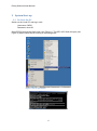
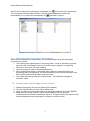
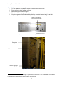
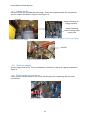
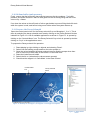
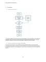
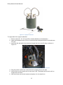
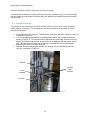
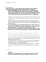
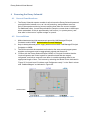
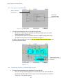
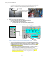
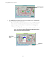
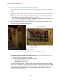
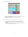
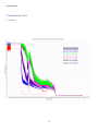
Decay Solenoid User Manual Decay Solenoid User Manual Decay Solenoid User Manual Contents 1 2 3 4 5 6 Introduction and system description ...................................................................... 2 1.1 Coldbox........................................................................................................ 3 1.2 Compressor System..................................................................................... 4 1.3 Decay Solenoid Cryostat .............................................................................. 5 System Start-up .................................................................................................... 6 2.1 Re-boot the PC ............................................................................................ 6 2.1.1 Recovering the system after a power outage .................................. 7 2.2 Switch on the Linde Fridge control cabinet ................................................... 7 2.3 Switch on the Linde Fridge ........................................................................... 8 2.4 Switch on the Chiller .................................................................................... 8 2.5 Check the air conditioning is on ................................................................... 8 2.6 Switch on controls rack ................................................................................ 9 2.7 Valves check .............................................................................................. 10 2.8 Check air supply ........................................................................................ 10 2.9 Visual inspection of turret ........................................................................... 10 2.10 Prepare the Decay Solenoid ...................................................................... 11 Cooldown ............................................................................................................ 12 3.1 Cooldown Process ..................................................................................... 12 3.2 Regenerating the Cryogenic Absorber ....................................................... 12 3.3 System Clean-up ....................................................................................... 14 3.4 Fridge and Magnet Cooldown .................................................................... 16 3.4.1 Preconditions for Fridge and Magnet Cooldown ... Error! Bookmark not defined. 3.4.2 Starting the Compressor............................................................... 16 3.4.3 Starting the Cooldown .................................................................. 17 3.4.4 Cooldown ..................................................................................... 19 3.5 Warm-up Instructions ................................................................................. 19 Powering the Decay Solenoid ............................................................................. 20 4.1 General Considerations ............................................................................. 20 4.2 Preconditions ............................................................................................. 20 4.3 Pre-power-up check list.............................................................................. 21 4.4 Preparing the Decay Solenoid for power .................................................... 21 4.5 Turning the Decay Solenoid Power Supply on ........................................... 24 4.6 Ramping the solenoid power supply down and making the system safe .... 25 Typical Cooldown Example: 12/2010 ................................................................. 26 5.1 Temperatures ............................................................................................ 26 5.2 Level and Mass Flow Rates ....................................................................... 27 5.3 Pressure .................................................................................................... 29 5.1 Current ....................................................................................................... 31 5.2 Control Valves............................................................................................ 32 Maintenance ....................................................................................................... 34 6.1 Opening the compressor to air for maintenance ......................................... 34 1 1 Introduction and system description 1.1 Coldbox 1.2 Compressor System MFM03/ /CLTS03 /PRE-07 /CLTS02 /PRE-06 /CGR01 /PRE-01 /MFM01 /MFM04 /CGR06 /CLTS01 /PRE-08 /MFM02 1.3 Decay Solenoid Cryostat CGR02/ PRE-02/ CGR04/ /CGR03PRE-04/ /PRE-03 N.B. Labels in yellow indicate sensor names in the Archiver /CGR05 /PRE-05 Decay Solenoid User Manual 2 System Start-up 2.1 Re-boot the PC Switch on the Linde PC and log in with: Username: CNRS Password: mice123 Open EPICS through the Start menu (see Figure 1). The OPC-IOC Shell will open (see Figure 2) which should be left running in the background. Figure 1: How to open EPICS Figure 2: OPC-IOC Shell 6 Decay Solenoid User Manual WinCC can be opened by selecting the ‘Quickstart’ icon found next to the start button. This will open the window shown Figure 2 and the Linde programme should start automatically. If not, select the activate/play icon , indicted in Figure 3. Figure 3: WinCC Explorer window 2.1.1 Recovering the system after a power outage When the DS losses power unexpectedly, the following things should be noted when recovering the system: The system often regains power in the wrong order. It may be necessary to power cycle the IOC so that when it turns on it receives all the signals it is expecting. Sensors on the mimic will need resetting Vacuum pumps will need to be switched back on. When resetting the heater in the helium bath, initially the interlocks will be red preventing this from happening. It will be necessary to reset all the interlocks in the PSU control window first and then reset the heater. The heater will reset by default to manual mode – this should be changed to automatic mode. 2.2 Switch on the Linde Fridge control cabinet 1. 2. 3. 4. Release emergency stop on front panel (pull outwards). Turn on mains breaker on front of the control panel. Clear any alarms on the control cabinet by alternately pressing ‘ACK’ and ‘ENTER’. Make sure the control cabinet is set to be controlled by the PC using the Local/remote control button indicated in Figure 4. The green light to the top-left of the button indicates that the compressor is currently in remote control. 7 Decay Solenoid User Manual Local/remote control Figure 4: Compressor control panel 2.3 Switch on the Linde Fridge 1. 2. 3. 4. Turn on the 3-phase power supply. Release the emergency stop on the front panel (rotate and pull outwards) Check the gate valves on air supply have come on. Check that the vacuum pump on the insulating vacuum behind the fridge has come on. 2.4 Switch on the Chiller 1. The water cooler is located to the right behind the compressor. It is turned on by switching on the power point located on the wall to the right and turning the switch indicated in Figure 5 on. The white light above the switch should come on and the display will show the water temperature, which should be in the region 16-20°C.. This is indicated by the line of LEDs on the gauge indicated in Figure 9 on the coldbox being lit. Power switch Figure 5: Cooling water supply 2.5 Check the air conditioning is on The air conditioning must be on in the hall – turn it on using (PRG-ENTER-ENTER) The compressor emit 85kW of heats, so if the air conditioning is not on the hall will overheat in 2 hours. The Compressor itself can work in up to 40°C, however the DS vacuum pumps and the DS C&M rack will fail at a hall temperature of ~35°C as measured at the East wall – this has happened in the past. The MOM notes refer to maintaining the hall to a temperature below 30°C. 8 Decay Solenoid User Manual 2.6 Switch on controls rack 1. 2. 3. 4. 5. Turn the isolators on (Master first) at the back of the control rack. From the front, switch on the computer. Switch the signal conditioning on. Check the vacuum gauges are on. Check the heater control switch for the Helium Cryostat is set to level 21 and that neighbouring switch is set to ‘FERN’ (remote) control as shown in Figure 6. Heater control switch should be set to level 2 Set switch to ‘FERN’ to allow remote control Figure 6: Heater control for Helium Cryostat Computer Signal conditioning Vacuum gauges Figure 7: DS Controls rack on the north mezzanine 1 This heater control setting is changing the power level in the heater. The on/off setting of the heater is controlled through the EPICS control system on a PID loop. 9 Decay Solenoid User Manual 2.7 Valves check Valves HV3100 and HV3200 should be open. These are located between the compressor and the coldbox as shown in Figure 9 and Figure 10. HV3200 Gauge indicating air supply pressure Gauge indicating turbine cooling water supply flow Figure 9: Turbine cooling water and air supply gauge Figure 9: Position of HV3200 HV3100 Figure 10: Position of HV3100 2.8 Check air supply The air supply must be on. This is indicated by a reading of 6 bar on the gauge indicated in Figure 9. 2.9 Visual inspection of turret Check for any obvious issues on the turret, including the fan is operating and any loose connections. Figure 11: Turret 10 Decay Solenoid User Manual 2.10 Helium buffer tank pressure Firstly, ensure that the buffer tank has sufficient pressure for the cooldown. The buffer pressure should be at least 6.5 bara: 4 bara goes into the DS during filling and the Linde cuts out if p < 2bara. If so close the valves to the refill pack of helium gas bottles to prevent filling the buffer tank while the system is cold, and hence losing more Helium when the system warms up. 2.11 Prepare the Decay Solenoid Open the control panel mimic for the Decay solenoid Cryo on Miceopipc 1, 2 or 3. This is done by selecting the decay solenoid work area by clicking on the ‘Decay Solenoid’ button indicated in Figure 12. A list of available applications as shown in Figure 13 is opened by clicking on the ‘Controls Menu’ icon. The Decay Solenoid Cryo mimic is opened by doubleclicking on ‘Cryo’ in the applications menu. To prepare the Decay solenoid for operation: 1. Reset display by right-clicking on objects and selecting ‘Reset’. 2. Switch first the backing pumps and then the turbo pumps on. 3. Open the valves between the decay solenoid vacuum and the pumps when then level of vacuum on either side of the valves is of a similar level. 4. Reset the Linde Quench Inhibit. 5. Switch the Air on (otherwise the valves cannot operate) 6. Check that the magnet is in ‘Safe Mode’ in the State Control. ‘Controls Menu’ icon ‘Decay Solenoid button Figure 12: Desktop of miceopipc1, miceopipc2 or miceopipc3 computers 11 Figure 13: Applications menu Decay Solenoid User Manual 3 Cooldown 3.1 Cooldown Process The system cleanliness is measured by the gas analyser. The gas analyser can be read via a webcam online which can be opened through the Application Launcher menu. The gas analyser is shown by Camera 6 and should give a reading of less than 10ppm. 3.2 Regenerating the Cryogenic Absorber The impurities removed from the helium flow by the absorber build up on the activated carbon absorber surface. In order to reuse the absorber it should be regenerated to remove impurities by heating to room temperature. This is done by inserting an electrical heater into the well. 12 Decay Solenoid User Manual Figure 14: Cryogenic absorber To regenerate the cryogenic absorber: 1. Ensure valves V1, V2, V3 and V5 are closed (labelled on the absorber). 2. Open the blowdown valve (V5) to a vacuum pump to depressurise the unit and leave V5 open. 3. Insert into the well within the absorber through the hole in the fill plug, as shown in Figure 15. Figure 15: Cryogenic absorber with heater inserted into well 4. Plug the power cord for the control box into a power point on the wall. 5. Set the timer on the control box for two hours. N.B. The heater should not be left on longer than two hours. 6. After two hours remove the heater and replace it in its control box. 13 Decay Solenoid User Manual Once the absorber is clean, disconnect the vacuum pump. If the absorber is allowed to warm up during the clean-up process (e.g. if it is left overnight and the clean-up continued the following day), the absorber should be pumped out before being reused. 3.3 System Clean-up The system is clean when both the H2O and N2 content are less than 10vpm (parts per million relative to volume). The compressor must be in operation so that there is a flow through the absorber. 1. Fill the absorber with nitrogen. The absorber is full when the level indicator is fully up, indicated in Figure 16. 2. Turn on the gas analyser which is located directly above the cryogenic absorber, shown in Figure 17. The flow should be adjusted using the black control to around 20mm. The pressure should be at 1bar and can be adjusted with the green control. N.B. The valve HV2173 (the start of the line from the buffer to the gas analyser, located on the DSA roof) must be open. 3. Start the flow through the gas analyser by opening valves HV2252 followed by HV2152, indicated in Figure 16. HV2252 HV2153 and HV2253 Level indicator HV2152 Figure 16: Cryogenic absorber and associated valves 14 Decay Solenoid User Manual Figure 17: Gas analyser The compressor should now be switched on so that the gas is flowing. 4. Open valves HV2253 followed by HV2153, indicated in Figure 16. The key to remove the padlock is held by the MOM and is labelled “LINDE ABSORBER VALVES”. This allows the gas to flow through the absorber. 5. The gas in the buffer tank can be cleaned by changing the high pressure setpoint between 8bar and 13bar. This forces gas in and out of the buffer tank. This is done by i. On the compressor mimic screen, left-click on PC2160, indicated in Figure 18, to open the ‘Compressor HP-Controller’ window. PC2160 Figure 18: Compressor mimic screen ii. iii. iv. v. Change the Setpoint value from 13.00 to 8.00. indicated in Figure 19. Wait for PI2160, indicated in Figure 18, to read ~8bar. Change the Setpoint value to 13.00. Continue until the impurity levels are below 10ppm. Ensure the final setpoint pressure is 13.00bar. Setpoint Figure 19: Compressor HPcontroller window 15 Decay Solenoid User Manual 6. If the fridge has been idle for a long time and/or there is any suspicion of air ingress, then it is good to clean the air inside the magnet. Only a small flow is acceptable in order not to put strain on the turbines. i. Change State Control on the ‘Decay Solenoid Cryo’ mimic to ‘Manual’ and then to ‘Start Cool Down’. ii. On the Coldbox mimic, open valve CV3170 by 10% to get a flow around the magnet. iii. Aim to get the incoming pressure at FI21 at ~5mBar (shown on the ‘Decay Solenoid Cryo’ mimic) iv. On the Coldbox mimic check CV3125 is partially open. Then open CV3135 by 3% - this is the return line from the radiation shields. v. Once the gas is clean in the magnet, change all the valves back to aurtomatic control. N.B. Be aware that the flow rates do not vary linearly with the % opening of the valves. Also it will not be possible to open PV 5510 manually at this point to clean the gas in that line, as the fridge will not allow it to be opened unless it considers it to be ‘ready’. 7. Once the gas is clean, close the valves allowing flow through the absorber - HV2153 valve followed by HV2253. 8. Close the valves allowing flow through the gas analyser. Close HV21523 first and allow the pressure in the gas analyser to drop to zero before closing HV2252. 3.4 Fridge and Magnet Cooldown Method statement and risk assessment must be agreed by Hall Manager and/or MOM and Authorisation to work obtained prior to starting the cooldown. 3.4.1 Starting the Compressor 1. Ensure the Compressor is in remote control - this is changed by pressing the Remote Control button ( ) on the front of the compressor. It is in remote control when the green light is on. 2. Check the start permissives of the compressor system on the visualisation in the MLCR by: i. On the MODE screen hover the mouse over ‘Compressor’ until a pen symbol appears, then left click. A new window should open as shown in Figure 20. Figure 20: Compressor start permissives window 16 Decay Solenoid User Manual ii. Check that all the permissives are ok - all the boxes down the right hand side of the window should be green. 3. If the permissives are ok, press the button in the MODE column next to Compressor on the visualisation, indicated in Figure 21. The compressor will now start up. A stable high and low pressure of 13.0 and 1.1 bar will be achieved. These are indicate on the compressor mimic as indicated in Figure 22. Click this button to start the compressor Click this button to start the cooldown Figure 21: MODE screen Pressure readings Figure 22: Pressure readings on compressor mimic 3.4.2 Starting the Cooldown 1. Wait at least 10 minutes until the compressor system has stabilized to a high and low pressure of 13.0 and 1.1 bar. 2. Check the pressures in the DS cryostat, which should be around 1.2bar – if the pressures are abnormally high, the fridge will not open CV3170 or CV3290 as the high pressure could damage the fridge. High pressures can be released by opening 17 Decay Solenoid User Manual PV5510 (using used to cool the current leads) which will allow the safe release of Helium back into the buffer tank. 3. Check the permissives for the coldmode visualisation by: i. On the MODE screen, hover the mouse over ‘Coldmode’ until a pen symbol appears. Left click to open a new window, as shown in Figure 24. ii. Check that all the permissives are ok – they should all be green. 4. If the permissives are ok, press the button next to COLDMODE in the MODE column, indicated in Figure 21. 5. Open the ‘MICE Pressure/Level Control’ window, shown in Figure 23, by selecting the “State Control” button in the bottom right hand corner of the “Decay Solenoid Cryo” mimic. Click on the “Start Cool DN” button in the ‘MICE Pressure/Level Control’ window. Figure 23: MICE Decay Solenoid Cryo Figure 24: Coldbox start permissives for coldmode window 18 Decay Solenoid User Manual 3.4.3 Cooldown The following sequence of actions is then carried out automatically by the refrigerator controls. All relevant valves are found either on the Cold-box or Cryostat mimic. 1. When the temperature of the outlet of turbine 2 (sensor TI3155 in the Cold-box) reaches 170K (after about 3 hours), the control valve on the inlet to the cryostat (CV3170) will automatically open to 100%. This allows the helium to flow through the magnet and start cooling it down. The control system sets CV1 to 20% and CV2 at 0%. The valve on the inlet to the heat-exchangers for the returning gas (CV3290) remains closed, so the helium gas return flow is directed through the one-way valve and PV3210, avoiding the heat-exchangers. The pressure inside the cryostat is about 12 bara, which then slowly decreases. Also, there is no flow through the shields at this stage. 2. When the temperature of the inlet of turbine 1 (sensor TI3130 in the Cold-box) reaches 230K (about five hours after start of cool-down), the control valve CV3125 will slowly open automatically to 100%. This allows helium to flow through the shield and start cooling it. 3. When the temperature of the gas returning from the cryostat (sensor TI3290 in the Cold-box) reaches 60K the control valve CV3290 will open to 100% and PV3210 will close to 0%. This re-directs the return flow of helium from the magnet through the heat exchangers. N.B. This will usually cause the fridge to warm slightly. 4. After CV3290 opens (step 3 above) the cool-down is controlled by a PID loop, where the limits are set in the ‘State Control’ window, in the ‘PID COOLDOWN flow control’ box. This loop limits the opening of CV1 such that the flow around the magnet (measured at FI01 is no more than the setpoint – currently 5mbar). The loop then checks that the temperature at TI21 isn’t rising more than 2K every 60mins – if it is, then the flow through the magnet is reduced by 0.1mBar. The aim of this is to ensure that the temperature of the cold trap (A3980) in the fridge (sensor TI3280) does not rise above 120K, when it could start to release contaminants back into the system. In a ‘normal’ cooldown, this should not be a problem. Linde advised that we should be concerned if the temperature of the cold trap reaches 120K, and to shut the fridge down if it reaches 150K. 5. During the start of the magnet cooldown Coils 1-5 and Coils 6-10 of the magnet are cooled in parallel. This is done automatically by the control system closing valve CV2, opening valve V12 and controlling valve CV1. When the temperature in the magnet reaches around 20K, the valves V12 and CV1 close and the J-T valve, CV2, opens. This redirects the helium to flow in series through Coils 1-5, Coils 6-10, and then the J-T valve to further cool and then fill the cryostat. 3.5 Warm-up Instructions To warm up the system: 1. Select the ‘Warm Up’ state in the MICE Decay Solenoid State Control shown in Figure 23. 2. In the Linde Fridge control system go to the ‘Modes’ screen, shown in Figure 26. Select any ‘On’ buttons in reverse order to the cooldown, to turn them to ‘Off’. 19 Decay Solenoid User Manual 4 Powering the Decay Solenoid 4.1 General Considerations 1. The Decay Solenoid experts consider it safe to leave the Decay Solenoid powered overnight and/or between runs, as it is self-protecting, and problems are more likely to be experienced during current ramping than when the current is stable. For additional safety, it would be preferable to ramp the current down to 400 Amps when unattended, as this is approximately half-current (i.e. quarter-power), and thus safer in the event of a power outage or quench. 4.2 Preconditions 1. Method statement and risk assessment agreed by Hall Manager/Principal Contractor and/or MOM. Authorisation to work obtained; 2. Keys to decay-solenoid power supply obtained from MICE Hall Manager/Principal Contractor or MOM; 3. The DSA must either be searched and locked or the area around magnet power supplies and magnets must be appropriately signed and fenced off; 4. Confirm with the Decay Solenoid Expert, MOM, or Principal Contractor that the Linde refrigerator and control system is operational and that the magnet, refrigerator, and helium reservoir have been in a stable operating state for an appropriate length of time. This is done by selecting the ‘Mode’ button indicated in Figure 25. It should read “Cooldown end. Refrigerator ready.” in the ‘State’ column and ‘Coldbox/Magnet’ as indicated in Figure 26. ‘Modes’ Button Figure 25: Screenshot of compressor mimic indicating ‘Mode’ button 20 Decay Solenoid User Manual 4.3 Pre-power-up check list Alarms or warnings indicated here. Should read “Cooldown ended. Refrigerator ready.” Figure 26: Screenshot of 'Modes' screen 1. On the Linde refrigerator mimic in the MLCR check that; i. No alarms or warnings are indicated (by flashing triangle at the top of the screen as shown in Figure 26); ii. The liquid helium level in the helium reservoir is stable (usually 80% level). The helium level of the reservoir is indicated in Figure 27. If either of these conditions is not met do not attempt to power the magnet, call the Decay Solenoid expert. Indicates liquid helium level in reservoir – should read 90%. Figure 27: Linde refrigerator mimic indicating the liquid helium level 4.4 Preparing the Decay Solenoid for power 1. Put the current-lead cooling into operation. Go into the Hall; i. Go to the decay solenoid gas panel on the east end of the north mezzanine and check that hand valve HV14 is open (in the vertical position as shown in Figure 29). If it is closed, open it; 21 Decay Solenoid User Manual ii. Check that the fan blowing air across the decay solenoid current leads on the platform in the DSA is on and appropriately positioned, see Figure 28; Appropriate position of fan on platform Figure 29: Hand valve HV14 shown in open position 2. Figure 28: Appropriate positioning of fan on platform On the Linde control panel operate PV5510: i. Hover over valve icon until a ‘pen’ appears and left click; ii. Click ‘Manual’ button on the pop-up menu; a. This will open the valve. The valve icon will change to green. b. Close the pop-up window that you just used to open the valve. Figure 30: Screenshot of Linde control panel indicating PV5510 control iii. PV5510 valve icon Verify that helium flow through the valves HCV31 and HCV32 as reported on the (EPICS-based) MICE decay solenoid mimic, shown in Figure 31, is stable and greater than 20 l/min (25 l/min is desirable but not a requirement) after a period of 30 minutes has elapsed; Note that it is necessary to allow approximately 30 minutes to elapse, to allow the refrigerator to stabilise and the current leads to reach operational temperature, during which the flow will steadily increase. If the flow has not stabilised at above 20 l/min after 30 minutes do not attempt to power the magnet, call the Decay Solenoid expert; 22 Decay Solenoid User Manual Readings for valves HCV31 and HCV32 Figure 31: MICE decay solenoid mimic indicating readings for HCV31 and HCV32 3. On the MICE Decay Soelnoid Cryo mimic, set the Linde Quench Inhibit selection button to the ‘Linde Quench Inhibit’ state: To set the Linde Quench Inhibit selection button to the ‘Linde Quench Inhibit’ state, click on the Linde Quench Inhibit status box on the main panel of the refrigerator mimic and select ‘On’ from the Linde Quench Inhibit window which opens. The status box will turn red with the words “Linde Quench Inhibit”, as seen in Figure 32; Note that the status box will turn green with the words “Linde Quench Active” when the active state is automatically enabled whenever the current through the solenoid exceeds 50 A. ‘On’ switch in the Linde Quench Inhibit window Linde Quench Inhibit status box Figure 32: Decay Solenoid Cryo mimic 23 Decay Solenoid User Manual 4.5 Turning the Decay Solenoid Power Supply on 1. Press the button on the side of the rack (for turning on power supply and ramping to 50A) 2. Unlock the main breaker indicated in Figure 33 on the power supply and turn the unit on. 3. Check the Set Values by pressing the ‘Set Values’ button and adjusting as needed. The normal operating set values are 875.5A and 6.5V. N.B. The PSU currently stops ramping somewhere slightly below the value set– so a set value of 875A will stop it ramping at 872A. 4. Reset the quench detector in the rack adjacent to the magnet power supply. Once reset, all LEDs on the panel should be off. ‘SET VALUES’ ‘On’, ‘Off’ and ‘Reset’ switch Mains breaker Figure 33: Power supply; located at the east end of the north mezzanine. 4. The power supply must now be prepared to be powered in the software using the MICE Decay Solenoid PSU mimic shown below. 1. Reset each of the controls in the mimic 2. Turn on the three controls in the following order: PSU EXT ILK (Ramp Down) PSU COOLER ILK (Fast) PSU ON On each of these controls – when the ‘ON’ button is selected, the state will change from ‘OFF’ to ‘TIMING’. It is necessary to hit ‘RESET’ on the power supply itself while the controls mimic reads ‘TIMING’ otherwise the controls mimic will go back to ‘OFF’. If the reset button is pushed in time, the controls mimic will show ‘ON’. The next control can then be switched on. 24 Decay Solenoid User Manual Figure 34: MICE DS PSU mimic 5. The power is then ramped up by selecting ‘Ramp to Set Current’ on the PSU control panel on the front of the PSU. 6. The button on the side of the rack must be released above 50A. 4.6 Ramping the solenoid power supply down and making the system safe 1. Select ‘Ramp to zero’ on the PSU control panel on the front of the PSU. The button on the side of the rack must be pressed in when the current goes below 50A. 2. When the current has reached zero, turn the power supply off using the button on the front of the PSU and the mains breaker. 25 Decay Solenoid User Manual 5 Typical Cooldown Example: 12/2010 5.1 Temperatures 26 Decay Solenoid User Manual 5.2 Level and Mass Flow Rates 27 Decay Solenoid User Manual 28 Decay Solenoid User Manual 5.3 Pressure 29 Decay Solenoid User Manual 30 Decay Solenoid User Manual 5.1 Current 31 Decay Solenoid User Manual 5.2 Control Valves 32 Decay Solenoid User Manual 33 Decay Solenoid User Manual 6 Maintenance 6.1 Opening the compressor to air for maintenance Prepare the system for being opened to air as follows: On DS mimic, close CV1 + CV2 On Cold-Box mimic, manually close o CV3170 + CV3290 o CV3125 + CV3135 o PV3210 + PV3122 + PV5510 Shut-down compressor On Compressor mimic, manually close o CV2160 + CV2150 + CV2250 Above compressor and Cold-Box, by hand, manually close o HV3100 + HV3200 At absorber, by hand, manually close o HV2140 + HV2180 At gas analyser, by hand,manually close o HV2152 + HV2252 o Power of the gas analyser Electrically isolate the compressor at the wall and lock off using padlock above isolation box Leave the compressor at pressure for HPC, who will then empty the system of oil and vent to air, 34