1
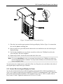
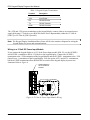
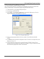
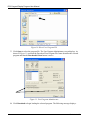
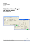
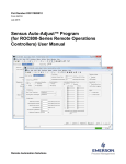
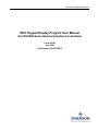
Remote Automation Solutions ROC Keypad Display Program User Manual (For ROC800-Series Remote Operations Controllers) Form A6162 June 2007 Part Number D301273X012 ROC Keypad Display Program User Manual Revision Tracking Sheet June 2007 This manual may be revised periodically to incorporate new or updated information. The revision date of each page appears at the bottom of the page opposite the page number. A change in revision date to any page also changes the date of the manual that appears on the front cover. Listed below is the revision date of each page (if applicable): Page All pages Initial release Revision Jun 07 Jun 04 © 2004-2007 Remote Automation Solutions, division of Emerson Process Management. All rights reserved. NOTICE Remote Automation Solutions (“RAS”), division of Emerson Process Management shall not be liable for technical or editorial errors in this manual or omissions from this manual. RAS MAKES NO WARRANTIES, EXPRESSED OR IMPLIED, INCLUDING THE IMPLIED WARRANTIES OF MERCHANTABILITY AND FITNESS FOR A PARTICULAR PURPOSE WITH RESPECT TO THIS MANUAL AND, IN NO EVENT SHALL RAS BE LIABLE FOR ANY INCIDENTAL, PUNITIVE, SPECIAL OR CONSEQUENTIAL DAMAGES INCLUDING, BUT NOT LIMITED TO, LOSS OF PRODUCTION, LOSS OF PROFITS, LOSS OF REVENUE OR USE AND COSTS INCURRED INCLUDING WITHOUT LIMITATION FOR CAPITAL, FUEL AND POWER, AND CLAIMS OF THIRD PARTIES. Bristol, Inc., Bristol Babcock Ltd, Bristol Canada, BBI SA de CV and the Flow Computer Division are wholly owned subsidiaries of Emerson Electric Co. doing business as Remote Automation Solutions (“RAS”), a division of Emerson Process Management. FloBoss, ROCLINK, Bristol, Bristol Babcock, ControlWave, TeleFlow and Helicoid are trademarks of RAS. AMS, PlantWeb and the PlantWeb logo are marks of Emerson Electric Co. The Emerson logo is a trademark and service mark of the Emerson Electric Co. All other trademarks are property of their respective owners. The contents of this publication are presented for informational purposes only. While every effort has been made to ensure informational accuracy, they are not to be construed as warranties or guarantees, express or implied, regarding the products or services described herein or their use or applicability. RAS reserves the right to modify or improve the designs or specifications of such products at any time without notice. All sales are governed by RAS’ terms and conditions which are available upon request. RAS does not assume responsibility for the selection, use or maintenance of any product. Responsibility for proper selection, use and maintenance of any RAS product remains solely with the purchaser and end-user. ii Revised Jun-07 ROC Keypad Display Program User Manual Table of Contents Page 1 INTRODUCTION.................................................................................................................................. 1 1.1 Scope and Organization ........................................................................................................... 1 1.2 Hardware Overview ................................................................................................................. 1 1.2 Program Overview ................................................................................................................... 2 1.3 Program Requirements ............................................................................................................. 2 2 INSTALLATION................................................................................................................................... 3 2.1 Installing the Keypad Display ................................................................................................. 3 2.1.1 How to Mount the Keypad Display .............................................................................. 3 2.1.2 How to Install the Visor................................................................................................6 2.1.3 How to Wire the Keypad Display for Power................................................................ 7 2.1.4 How to Wire the Keypad Display for Communications............................................... 9 2.2 Downloading the KeypadDisplay.tar Program ..................................................................... 11 3 CONFIGURATION ............................................................................................................................. 15 3.1 Device Information Keypad Display Tab .............................................................................16 3.2 Comm Port General Tab ....................................................................................................... 18 3.3 Saving the Configuration ...................................................................................................... 20 4 REFERENCE MATERIALS ............................................................................................................... 23 4.1 Operating the Keypad Display ..............................................................................................23 4.1.1 Logging In................................................................................................................... 24 4.1.2 Accessing the Main Menu and Other Menus.............................................................. 25 4.1.3 Logging Out................................................................................................................ 28 4.2 Point Type 236: Display Configuration ................................................................................ 29 Revised Jun-07 iii ROC Keypad Display Program User Manual iv Revised Jun-07 ROC Keypad Display Program User Manual 1 INTRODUCTION 1.1 Scope and Organization This document serves as the user manual for the ROC Keypad Display and program, which is intended for use in the ROC800-Series Remote Operations Controllers (“ROC800s”). This manual describes how to install the ROC Keypad Display (“the keypad display”) and how to download, install, and configure the ROC Keypad Display program (“the program”). You access and configure this application using ROCLINK™ 800 Configuration Software loaded on an IBM-compatible personal computer running Windows® 98, NT 4.0 (with Service Pack 6), 2000 (with Service Pack 2), or XP. The sections in this manual provide information in a sequence appropriate for first-time users. Once you become familiar with the device, the procedures, and the software, the manual becomes a reference tool. This manual has the following major sections: Section 1 – Introduction Section 2 – Installation Section 3 – Configuration Section 4 – Reference Materials This manual assumes that you are familiar with the ROC800s and their configuration. For more information, refer to the following manuals: ROC809 Remote Operations Controller Instruction Manual (Form A6116) ROC827 Remote Operations Controller Instruction Manual (Form 6174) ROCLINK 800 Configuration Software User Manual (for ROC800-Series) (Form A6218) 1.2 Hardware Overview The ROC Keypad Display has two liquid crystal display (LCD) screens, two light-emitting diodes (LEDs), and 25 keypad buttons (see Figure 1). Figure 1. ROC Keypad Display Revised Jun-07 1 ROC Keypad Display Program User Manual You can configure the LCD screen to display either black letters on a white background or white letters on a black background. The LEDs display in two colors to denote alarm or function status of the keypad. Refer to Section 2.1 for instructions on installing the keypad and to the specifications sheet 6.5:RKD, ROC Keypad Display (ROC800-Series), for device specifications. See Section 4.1 for instructions on using the keypad. Note: The keypad display is designed either for panel or enclosure mounting. See Section 2.1 for installation instructions. 1.2 Program Overview The ROC Keypad Display program is designed as an interface between ROC800-Series Remote Operations Controllers (ROCs) and the ROC Keypad Display. The program manages the writing of information to the display and reads and decodes the keystrokes which control the information displayed. 1.3 Program Requirements The application is compatible with version 2.02 (or greater) of the ROC800-Series firmware and with version 1.74 (or greater) of the ROCLINK 800 software. Program specifics include: File Name Target Unit/ Version User Defined Point (UDP) Flash Used (in bytes) SRAM Used (in bytes) DRAM Used (in bytes) ROCKLINK 800 Version KeypadDisplay.tar ROC800 2.02 236 138,240 7,342 270,356 1.74 Note: You must connect a PC to the ROC800’s LOI port before starting the download. For information on viewing the memory allocation of user programs, refer to the ROCLINK 800 Configuration Software User Manual (for ROC800-Series) (Form A6218). 2 Revised Jun-07 ROC Keypad Display Program User Manual 2 INSTALLATION This section provides instructions for installing the physical ROC Keypad Display and for installing and configuring the ROC Keypad Display program. You must install the keypad display before you install and configure the program. Read Section 1.3 of this manual for program requirements. 2.1 Installing the Keypad Display Note: The keypad display is designed for panel or enclosure mounting. The keypad display enables you to access ROC800 process and operational information and view and change ROC800 parameters. When powered, the keypad display shows ROC800 values in real time. Using the 25 multi-function keys, you can browse through lists and screens, type text, and enter numeric value. Any changes you make using the keypad display take immediate effect in the ROC800. See Table 4 in Section 4.1 for a list of actions for each keypad display button. The ROC800 uses any EIA-232 (RS-232) port to communicate with the keypad display. The keypad display requires 10 to 30 Volts dc and can be powered either by the ROC800’s power module or an external power source. You need the following tools to install, remove, or wire a keypad display: Phillips screwdriver, size 2. Flat blade screwdriver, size 2.5 mm (0.10 inch). Electric screwdriver, tip size 2 (can be portable battery-driven style). Drill with 5.5 mm (0.219) inch drill bit. 1¼ inch knockout punch. Wrench to accommodate #8 hex nuts. The keypad display itself requires no configuration. Any configuration occurs at the program level using ROCLINK 800 software. Refer to Section 2.2 for software configuration instructions. 2.1.1 How to Mount the Keypad Display Review the following guidelines for mounting the keypad display: Enclosure Mounting Panel Mounting If you intend to panel-mount the keypad display, you can remove the gasket attached to the back of the keypad display. If the panel has not been pre-cut, follow steps 1 through 9. If the panel has been pre-cut, follow steps 7 through 9. If you intend to mount the keypad display in a ROC800-Series enclosure (Models EN23 or EN37 or other Type 4 enclosure), you must use the gasket attached to the back of the keypad display Review steps 1 through 6 to appropriately prepare the enclosure before mounting the keypad display. Revised Jun-07 3 ROC Keypad Display Program User Manual Note: The keypad display ships from the factory accompanied by a three-page Installation Sheet (Form A6164, Revision E). Use the graphic on Page 3 of that Installation Sheet as the template for Step 1. Figure 2 presents a reduced version of that graphic. However, ensure that the drawing you use for the template is to scale. 3.76 [95.5] .98 [24.9] B 1.13 [28.6] B A 3.36 [85.3] A 6.72 [170.7] DO NOT PUNCH - USE FOR ORIENTATION ONLY. LOCATION OF THREADED INSERTS OF EXISTING DISPLAY CUTOUT ON FISHER EN23 & EN37 ENCLOSURES. B B 2.42 [61.5] DISPLAY OUTLINE C B B 1.88 [47.8] DOC0571B Figure 2. Keypad Display Installation Template (not to scale) 1. Copy Figure 2 to a sheet of paper that you can discard when finished. Reduce or enlarge the drawing until Figure 2 is to scale. Note: You can also use page 3 of the Keypad Display Installation Sheet (Form A6164, Revision E) as the template for Step 1. However, ensure that whatever drawing you use for the template is to scale. 2. Attach the sheet of paper with Figure 2 to the enclosure. Position the paper so that the line marked 3.76 [95.5] is towards the top of the enclosure. If you are installing on an EN23 or EN37 enclosure door, align the two locations marked A with the threaded inserts on either side of the existing display cutout. 3. Center-punch at the locations marked B and C (a total of seven punches). 4 Revised Jun-07 ROC Keypad Display Program User Manual 4. Remove the sheet of paper with Figure 2 and drill 5.6 mm (0.219 inch) diameter holes at six locations marked B. 5. Punch a 44 mm (1.25 inch) diameter knockout hole at the location marked C. 6. Deburr all edges and apply a touch-up coating of paint (not provided) to raw edges of the enclosure or panel for corrosion protection. 7. Install washers and set screws (provided) on the backplate of the keypad display (refer to Figure 3. Washer Set Screw Gasket Figure 3. Backplate of Keypad Display 8. Place six set screws through the six drilled holes in the enclosure or panel. Press the keypad display against the enclosure or panel. 9. Attach the keypad display to enclosure or panel with supplied 8-32 hex nuts (refer to Figure 4). Revised Jun-07 5 ROC Keypad Display Program User Manual Enclosure wall Hex Nut View D Figure 4. Side View of Installed Keypad Display This completes the installation of the keypad display on a panel or enclosure. Proceed to Section 2.1.2 if you need to install a visor on the keypad display or to Section 2.1.3 to wire the keypad display. 2.1.2 How to Install the Visor The visor shades the display so you can see it easily in direct sunlight (see Figure 5). Typically, the visor is factory-installed unless you order it later as a kit. If you order a visor kit, a Keypad Display Visor Installation Sheet (Form A6176) accompanies the kit. 6 Revised Jun-07 ROC Keypad Display Program User Manual Figure 5. Keypad Display with Installed Visor 1. Place the visor onto the upper portion of the keypad display. Refer to Figure 5 to ensure that the visor fits into the retaining tabs. 2. Insert a small screw (provided) into the hole on the visor and hole in one side of the keypad display housing. 3. For first time installation, use an electric screwdriver with a size 2 Phillips bit to drive the screw into place. Do not overtighten. 4. Repeat steps 2 and 3 for the hole on the other side of the visor. Note: If you are reinstalling the visor, use a manual (not electric) size 2 Phillips screwdriver to prevent stripping the screw’s threads. You may need to initially reverse the direction of the screw to engage it fully. To remove the visor, simply unscrew each side of the visor. Keep the screws; the holes in the sides of the keypad display require this type of fastener. 2.1.3 How to Wire the Keypad Display for Power You use the termination block accessible through the cutout on the back of the keypad display (see Figure 3) to connect wiring for the power and EIA-232 (RS-232) communications. Table 1 shows the power and communications terminations. The terminals accept wires 16 AWG or smaller. Bare at least 5 mm (0.2-inch). Tighten the terminals to 0.22 N-m (1.95 in-lb). Revised Jun-07 7 ROC Keypad Display Program User Manual Table 1. Keypad Display Terminations Terminal +VIN Description Input Power + -VIN Input Power – RX RS-232 Receive TX RS-232 Transmit COM RS-232 Common The +VIN and -VIN power terminations on the keypad display connect either to an external power supply delivering 12 Volts dc or to a ROC800-Series Power Input module (either the 12 Volts dc [PM-12] or 24 Volts dc [PM-24] model). Note: The Keypad Display Installation Sheet (Form A6164) also contains a diagram for wiring the keypad display for power and communications. Wiring to a 12 Volt DC Power Input Module If you connect the keypad display to a 12 Volt dc Power Input module (PM-12), use the AUXSW+ and AUXSW– terminals to deliver 12 Volts dc to the keypad display. Connect the AUXSW+ termination to the +VIN termination of the keypad display and the AUXSW– termination to the –VIN (Input Power –) termination of the keypad display. You can use the AUX+ and AUX– terminations, but the AUXSW terminations allow the ROC800 to switch off the keypad display in power-loss situations. Refer to Figure 6. POWER MODULE PM-12 EXAMPLE SHOWN RED BLK +VIN -VIN RX TX COM A123456 DOC0576B Figure 6. 12 Volts dc Power Input Module Wiring 8 Revised Jun-07 ROC Keypad Display Program User Manual Wiring to a 24 Volt DC Power Input Module If you connect the keypad display to a 24 volts dc Power Input module (PM-24), use the AUX+ and AUX– terminals to deliver 12 Volts dc to the keypad display. Connect the AUX+ termination to the +VIN termination of the keypad display and the AUX- termination to the –VIN (Input Power –) termination of the keypad display. Refer to Figure 7. Figure 7. 24 Volts dc Power Input Module Wiring Wiring to an External Power Source If you connect the keypad display to an external power source, connect the + termination to the +VIN termination and the – termination to the –VIN termination of the keypad display. 2.1.4 How to Wire the Keypad Display for Communications The TX, RX, and COM terminations on the keypad display connect to the RX, TX, and GND terminations on an EIA-232 (RS-232) communications port on a ROC800. The EIA-232 (RS-232) port can be either the Comm 2 port on the CPU or an optional communications module (Comm 3, Comm 4, or Comm 5). Table 2 shows the EIA-232 connections; Figure 8 shows an example of the communications wiring. Table 2. EIA-232 (RS-232) Terminations Revised Jun-07 Terminal RX Keypad Display Connection Connect to Keypad Display TX. TX Connect to Keypad Display RX. RTS N/C DTR N/C GND Connect to Keypad Display Common. 9 ROC Keypad Display Program User Manual Figure 8. Communications Wiring (CPU Comm 2 Port Shown) 10 Revised Jun-07 ROC Keypad Display Program User Manual 2.2 Downloading the KeypadDisplay.tar Program This section provides instructions for installing the KeypadDisplay.tar program file into the Flash memory on the ROC800. To download the program using ROCLINK 800 software: 1. Connect the ROC to your computer using the LOI port. 2. Start and logon to ROCLINK 800. 3. Select Utilities > User Program Administrator from the ROCLINK menu bar. The User Program Administrator screen displays (see Figure 9): Figure 9. User Program Administrator 4. Select any empty program number (in this case, number 1) into which to download the program. 5. Click Browse in the Download User Program File frame. The Select User Program File screen displays (see Figure 10). 6. Select the path and user program file to download from the CD-ROM. (Program files are typically located in the Program Files folder on the CD-ROM.) As Figure 10 shows, the screen lists all valid user program files with the .TAR extension: Revised Jun-07 11 ROC Keypad Display Program User Manual Figure 10. Select User Program File 7. Click Open to select the program file. The User Program Administrator screen displays. As shown in Figure 11, note that the Download User Program File frame identifies the selected program and that the Download & Start button is active: Figure 11. User Program Administrator 8. Click Download to begin loading the selected program. The following message displays: 12 Revised Jun-07 ROC Keypad Display Program User Manual Figure 12. Confirm Download 9. Click Yes to begin the download. When the download completes the following message displays: Figure 13. ROCLINK 800 Download Confirmation 10. Click OK. The User Program Administrator screen displays (see Figure 14). Note that: The Device User Program Environment frame reflects the use of system memory. The User Programs Installed in Device frame identifies the installed program. The Status field indicates that the program is running. Figure 14. User Program Administrator 11. Proceed to Section 3 to configure the program. Revised Jun-07 13 ROC Keypad Display Program User Manual 14 Revised Jun-07 ROC Keypad Display Program User Manual 3 CONFIGURATION Note: Before you begin the process of configuring ROCLINK 800, ensure you have correctly wired the keypad display (in accordance with Form A6164 or Sections 2.1.3 and 2.1.4 of this manual) and connected the keypad display to your ROC800. After you have downloaded and started the Keypad Display program, you use two standard ROCLINK 800 screens to configure the program: Use the Keypad Display tab on the Device Information screen (ROC > Information) to set general parameters for the keypad display. Use the General tab on the Comm Port screen (ROC > Comm Ports) to set communicationspecific parameters for the keypad display. Note: After configuring these screens, you should restart your ROC800 using a warm start from the Flags screen (ROC > Flags > Warm Start). This ensures that the ROC800 firmware recognizes your modified configuration. You can access all screens from the main ROCLINK 800 screen: Figure 19. ROCLINK 800 Revised Jun-07 15 ROC Keypad Display Program User Manual 3.1 Device Information Keypad Display Tab Use this tab to set general parameters for the keypad display. To access this screen: 1. Select ROC > Information. The Device Information screen displays, showing the General tab. 2. Select the Keypad Display tab. The Keypad Display screen displays. Figure 20. Device Information Keypad Display Tab 3. Review the following fields for your organization’s values: Field Description LCD Master Switch Sets whether the ROC800 runs the Keypad Display program. Valid values are On (the Keypad Display program is running on the ROC800) or Off (the Keypad Display program is stopped). The default is On. LCD Status This read-only field shows the operational status of the keypad display. If the keypad display is functioning correctly, the field displays OK. If the keypad is not installed or is otherwise not functioning correctly, the field displays LCD Not Installed. LCD Video Mode Sets the keypad display. Valid values are Dark Text on Light Background or Light Text on Dark Background. The default is Dark Text. LCD Backlight Power Saving Mode Sets a power saving mode for the keypad display. Valid values are Enabled (the backlight turns off after a specified time) or Disabled (the backlight is always on). The default is Disabled. Note: If you select Enabled, you must also complete the Inactivity Time field which indicates, in minutes, how long the backlight remains on. 16 Revised Jun-07 ROC Keypad Display Program User Manual Field Description LCD Firmware Version This read-only field shows the current version of LCD firmware installed in the ROC800. Auto Logout Period Sets, in minutes, how long the keypad waits before automatically logging off the current user. The default is 30 minutes. Logout Scroll Time Sets, in seconds, how frequently the program refreshes the loaded configuration’s default “screen saver” program. If the screen saver contains more than 8 lines, this value indicates how frequently the program rotates through the first 8 lines and then moves to the next 8-line display. You define the content of this “screen saver” using the Keypad Display Editor screen (Utilities > Keypad Display Editor). A screen saver can have as many lines as necessary. The display shows 8 lines at a time; this value indicates how long the display shows each 8-line display before the keypad proceeds to the next 8 lines in the defined screen saver. 4. Click Apply to save your changes. 5. Click OK to close the screen. Proceed to Section 3.2 to configure communications. Revised Jun-07 17 ROC Keypad Display Program User Manual 3.2 Comm Port General Tab Use the General tab on this screen to define communications parameters specific to the keypad display. To access this screen: 1. Select ROC > Comms Ports. The Comm Port screen displays. Figure 21. Comm Port General Tab 2. Review the following fields for your organization’s values: Field Description Comm Ports Sets the communication port associated with the keypad display. Typically this is COMM2, although you can set the keypad active on COMM1 or COMM3. Click d to display all comm ports. Note: You cannot configure the LOI or Local Port for use with the keypad display. 18 Tag Sets a 10-character identifier for the comm port. ROCLINK 800 includes this tag as part of the value shows in the Comm Ports field. Comm Type This read-only field shows the type of communication protocol associated with the selected comm port. Baud Rate Sets a communications rate (baud rate) for the port. The Keypad Display program requires 57.6 K. Revised Jun-07 ROC Keypad Display Program User Manual Field Description Parity Sets the parity parameter for the communications protocol. The Keypad Display program requires None. Data Bits Sets the data bits parameter for the communications protocol. The Keypad Display program requires 8 data bits. Stop Bits Sets the stop bits parameter for the communications protocol. The Keypad Display program requires 1 stop bits. Key On Delay Sets, in seconds, how long ROCLINK 800 waits before sending a signal to the keypad display. Set this value to 0.0 to prevent signal delay. Key Off Delay Sets, in seconds, how long ROCLINK 800 waits before turning off the signal to the keypad display. Set this value to 0.0 to prevent signal delay. Port Owner Sets the program or device that ROCLINK 800 associates with this comm port. Select LCD for the Keypad Display program. Note: Do not select a User Program. The Keypad Display program automatically selects a program internally. 3. Click Apply to save any changes you have made to this screen. 4. Proceed to Section 3.3 to save this configuration. Revised Jun-07 19 ROC Keypad Display Program User Manual 3.3 Saving the Configuration Whenever you modify or change the configuration, it is a good practice to save the final configuration to memory. To save the configuration: 1. Select ROC > Flags. The Flags screen displays: Figure 22. Flags screen 2. Click Save Configuration. A verification message displays: Figure 23. Perform screen 20 Revised Jun-07 ROC Keypad Display Program User Manual 3. Click Yes. A confirmation message displays: Figure 24. Flags screen 4. Click OK to begin the save process. The Status field on the Flags screen displays In Progress. When the process ends, the Status field on the Flags screen displays Completed. 5. Click Update on the Flags screen. This completes the process of saving your new configuration. Note: For archive purposes, you should also save this configuration to your PC’s hard drive or a removable media (such as a diskette or a flash drive) using the File > Save Configuration option on the ROCLINK 800 menu bar. Revised Jun-07 21 ROC Keypad Display Program User Manual 22 Revised Jun-07 ROC Keypad Display Program User Manual 4 REFERENCE MATERIALS This section provides detailed instructions on operating the keypad display as well as information on point type 236, which the Keypad Display program uses. 4.1 Operating the Keypad Display Note: The sample keypad screens in this section are only examples. The screens in your environment may change depending on programs installed in your ROC800s or user security. After you have activated and configured the keypad display, you can use it to access information on the ROC800. 800 Keypad Display ALARM 7 0 , Figure 25. Keys on Keypad Display Thirteen keys on the keypad (see Figure 25) have three alphanumeric values. The upper left character is red, the center character is black, and the lower right character is blue. You press the SHIFT/ALT key (note that the word SHIFT is red and the word ALT is blue) to access the various values. The SHIFT/ALT LED to the right of the lower display turns different colors and blinks to indicate the current value. Table 3. LEDs on Keypad Display LED Function Solid Red Shift/Alt Action Pressed1 time Function Action Accesses the red characters on the pads in upper case. Solid Blue Pressed 2 times Accesses the blue characters on the pads in upper case. Revised Jun-07 23 ROC Keypad Display Program User Manual LED Function Blinking Red Shift/Alt Action Pressed 3 times Function Action Accesses the red characters in lower case. Blinking Blue Pressed 4 times Accesses the blue characters in lower case. No Light Not pressed or Shift held down for 1 second or longer Accesses the black numbers and punctuation. Table 4 shows the actions for the non-alphanumeric keys. Table 4. Keys on Keypad Display Keypad Button PREV Action Returns to previous list of sub-menu options. Note: This key is available only if < displays in the lower left corner of the screen. F1 Selects the left sub-menu option. If it points to Log#-, it decreases the logical number of the point being displayed. If it points to another screen, it opens the screen. F2 Selects the middle sub-menu option. If it points to Log#+, it increases the logical number of the point being displayed. If it points to another screen, it opens the screen. F3 Selects the right sub-menu option, if one is there. Typically points to another screen that it will open. NEXT Goes to next list of sub-menu choices. Note: This key is available only if > displays on the bottom line of the screen. BKSP Moves cursor back one space in Edit mode and deletes the last character. Í (Left Arrow) Returns display from sub-menu to next higher menu. Î (Right Arrow) Takes display to highlighted sub-menu. ENTER has the same action. Ð (Down Arrow) Highlights item below the currently highlighted item. Ï (Up Arrow) Highlights item above the currently highlighted item. SHIFT/ALT Enters Function mode. See table above for Function actions. ENTER Takes display to highlighted sub-menu or saves values of pressed keypad buttons. 4.1.1 Logging In After you activate the keypad display, the Log-in display shows on the lower screen (see Figure 26): Login: LOI Password: **** Figure 26. Log-in (Defaults Shown) You can enter any valid login ID and password defined on the ROC800 using ROCLINK 800. Caution 24 The keypad display does not support access levels. Using the keypad display, any valid login ID and password can access all ROC800 menus and submenus. Revised Jun-07 ROC Keypad Display Program User Manual For example, to type LOI (the default ROC800 logon ID), press SHIFT/ALT once. The SHIFT/ALT LED next to the lower display turns red, indicating you have access to the red values on the keys. Press the L key (bottom row, second from the left). Press SHIFT/ALT again, and the SHIFT/ALT LED turns blue, indicating that you have access to the blue values on the keys. Press the O key (third row, second from the left). Press SHIFT/ALT four times. The SHIFT/ALT LED turns red again, indicating that you have access to the red values on the keys again. Press the I key (fourth row, second from right) and then press ENTER. To type 1000 (the default logon password), press SHIFT/ALT four times (or hold the SHIFT/ALT key for 1 second). The SHIFT/ALT LED turns off. This gives you access to the black (numeric) values on the keys. Press 1000 and ENTER to complete the logon sequence. Refer to Table 3 for the relationship between the LED colors and patterns and pressing SHIFT/ALT. 4.1.2 Accessing the Main Menu and Other Menus After you complete the login, the keypad display’s main menu displays (see Figure 27). 1 2 3 4 5 6 7 8 IO Control Meter System Events Alarms IO Calibration Logout Figure 27. Main Menu To select an option, use the Ï and Ð keys on the keypad to highlight an option and press ENTER. For example, if you select the Meter option, the following screen sequence could display: 1 Station Figure 28. Station Menu Revised Jun-07 25 ROC Keypad Display Program User Manual 1 Station Information 2 Meter Runs Figure 29. Station Sub-Menu Station Information 1 Point Tag Station 1 Flow Rate 0.00 Flow Today 0.00 Flow Yday 0.00 Energy Rate 0.00 Energy Today 0.00 Log# - Log# + Figure 30. Station Information Data Screen Some of the information on this screen (such as flow rates, flow totals, energy rates, and energy totals) is display-only; you cannot change it. (If the screen contains 8 or more lines of information, use the Ï and Ð keys on the keypad to view those additional lines.) But you can, for example, change the tag associated with this station number by selecting that line and pressing ENTER. The highlighting jumps to Station 1, as shown in Figure 31. Station Information 1 Point Tag Station 1 Flow Rate 0.00 Flow Today 0.00 Flow Yday 0.00 Energy Rate 0.00 Energy Today 0.00 Cancel Reset OK Figure 31. Station Information Data Screen Use the keys on the keypad to relabel Station 1. Note also that the displays at the bottom of the screen have changed, and are now labels for the F1, F2, and F3 keys on the keypad. Pressing those keys enables you to, respectively, cancel, reset, or OK the change. In a similar way, Figure 30 shows that F1 has the label Log# –and F2 has the label Log# +. Using the F1 and F2 keys, you can page through the logical iterations (stations) define for this meter, and view information for Station 2, Station 3, and so on. Figure 32 shows one of two RTD input screens: 26 Revised Jun-07 ROC Keypad Display Program User Manual RTD 8-1 Point Tag RTD Deflt Units Tag deg C EU Value 350.00 Log# - Log# + Figure 32. RTD Information Screen Use the F1 or F2 key to review the values for the RTDs defined for the ROC800. Finally, Figure 33 shows an event log, which lists events on the lower screen and provides event details on the upper screen: Param Change Event Operator: LOI Type :RTD Logic: 128 Param: UNITS Data Type : STRINGØ New Val: deg C Events 1 15:41:11 06/06/07 2 15:41:11 06/06/07 3 15:41:11 06/06/07 4 15:41:11 06/06/07 5 15:41:11 06/06/07 6 15:41:11 06/06/07 Up Down New Figure 33. RTD Information Screen (both upper and lower displays) Here the F1, F2, and F3 keys have been assigned values of Up, Down, and New, enabling you to move up and down the event log. Press New to assign a description for a new event. Revised Jun-07 27 ROC Keypad Display Program User Manual 4.1.3 Logging Out When you are finished with this session using the keypad display, select the Logout on the Main menu and press ENTER. This logs you out and redisplays the login screen (Figure 26). Caution 28 Logging out is essential for security. Although the keypad display automatically logs users off after the period you define on the Keypad Display tab on the Device Information screen (see Figure 20), until that period expires, anyone with a valid login ID and password can access all ROC800 menus and submenus. Revised Jun-07 ROC Keypad Display Program User Manual 4.2 Point Type 236: Display Configuration Point type 236 contains the parameters defining selections for the keypad display. The program maintains one logical point for each keypad and saves point type 236 information to internal configuration memory. 0 1 Reserved LCD Status R/O R/O Program or User Update SYSTEM USER 2 LCD Video Mode R/W USER UNIT8 1 0Æ1 0 1.0 3 LCD Power Save Time R/W USER UINT8 1 0 Æ 255 0 1.0 4 LCD Auto Logout Period R/W USER UINT8 1 0 Æ 255 30 1.0 5 LCD Logout Scroll Time R/W USER UINT8 1 1 Æ 255 5 1.0 Parm # Name Revised Jun-07 Access Data Type Length Range Default Version UINT8 UINT8 1 1 0 Æ 255 0Æ4 0 0 1.0 1.0 Description of functionality and meaning of values Indicates Current LCD Status 0: OK 1: Invalid Display Conf File 2: Display Conf File CRC Error 3: LCD Not Installed 4: Unknown Error Select between dark text on light background or light text on dark background. 0: Dark on Light 1: Light on Dark Enables/Disables the power saving feature of the LCD 0: Disable Power Saving When set to anything greater then 0, that will be the number of minutes of inactivity required before placing the LCD into sleep. The Time Out Period for the keypad auto logout. This is in Minutes. The number of seconds between updates of screen shown when user is logged out. 29 ROC Keypad Display Program User Manual If you have comments or questions regarding this manual, please direct them to your local sales representative or contact: Emerson Process Management Remote Automation Solutions Marshalltown, Iowa 50158 USA Houston, TX 77065 USA Watertown, CT 06795 USA Pickering, North Yorkshire UK Y018 7JA 30 Revised Jun-07 ROC Keypad Display Program User Manual Revised Jun-07 31