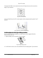
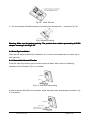
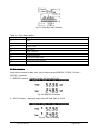
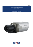
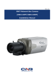
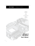
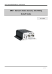
1
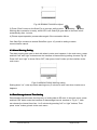
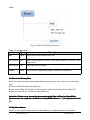
Solar Eye User Manual
Edition <1.
1>
<1.1
JIANGSU EVER-SOLAR NEW ENERGY CO., LTD.
Revision History
Date
Edition
Specification
17/08/2011
1.0
Create File
02/09/2011
1.1
Add Micro SD function
description
www.ever-solar.com
Page 1 of 25
Table of Contents
1. Introductions...................................................................................................................................... 3
1.1 Packing List........................................................................................................................... 3
1.2 Safety and Notes.................................................................................................................. 4
2. Product Installation............................................................................................................................4
2.1 Connecting Solar Bee and Straight Networking Cable....................................................4
2.2 Solar Bee Wall Attach Installation...................................................................................... 5
2.3 SD Card (Optional) in Solar Eye and Battery Installation................................................6
2.4 Solar Eye Installation........................................................................................................... 7
2.4.1 Detachable Chassis Fixation.................................................................................7
2.4.2 Wall Mounting......................................................................................................... 7
3. Interface Introduction........................................................................................................................ 8
3.1 Main Interface....................................................................................................................... 8
3.2 Sub Interface.........................................................................................................................9
4. Set & Operation...............................................................................................................................10
4.1 Initial Setting........................................................................................................................10
4.1.1 Set Time................................................................................................................ 10
4.1.2 Set Currency......................................................................................................... 10
4.1.3 Set Yield Coefficient.............................................................................................11
4.1.4 Set Emission Coefficient......................................................................................11
4.2 Wireless Connection.......................................................................................................... 11
4.2.1 Connection Type.................................................................................................. 12
4.2.2 Set Up Wireless Connection............................................................................... 12
4.3 Alarm Warning Setting.......................................................................................................13
4.4 Data Storage Interval Time Setting..................................................................................13
4.5 Restore Factory Default Settings..................................................................................... 13
4.6 History Energy and Power Value Yield View.................................................................. 14
4.7 Micro SD File Structure Description.................................................................................14
4.8 Check the History Data......................................................................................................15
4.9 Update software................................................................................................................. 15
5. Reference:........................................................................................................................................16
6. Error Message................................................................................................................................. 17
7. Contact............................................................................................................................................. 19
www.ever-solar.com
Page 2 of 25
1. Introductions
Solar Eye is desktop monitoring device, developed for home and small commercial PV solar
system. This device is able to monitor up to 5 inverters simultaneously, transfer data through
wireless network and display relevant data on the LCD.
Features:
Integrated Large LCD display
Multiple display - Graph or bar chart display options
● Wireless Technology (Up to 150 meter in open area and up to 100 meter in building)
● Retro fit on any Ever-solar inverter, monitor up to 5 inverters
● Micro SD card storage for history monitoring data
● Real time monitoring of Power Generation, Export value and Carbon Saving
●
●
1.1 Packing List
The packing list of Solar Eye as below:
A
B
G
H
C
D
I
E
F
J
K
Table 1-1 Packaging List
Location
A
Quantity
1
Name
Solar Eye
Purpose
Display terminal of inverter data
B
1
Solar Bee
Collect inverter data
C
1
Waterproof Seal Sets
Secure water and dust protection of Solar Bee
(IP65)
D
1
Operating&
Instruction
Product operating & installation instruction
E
4
wall plug
For Solar Bee wall mounting
F
2
Screw ST2.7×6
Fix the suspension loop to Solar Bee
G
2
Solar Bee Suspension Loop
For Solar Bee wall mounting
H
1
The base of Solar Eye
For Solar Eye installation on the table
I
4
Screw ST3×25
For Solar Bee & Solar Eye wall mounting
www.ever-solar.com
Installation
Page 3 of 25
J
1
Direct network
Cable between Solar Bee & inverter
K
1
Quick installation guide of
Solar Eye
Product quick installation guide
1.2 Safety and Notes
1)Read the instructions before installation
2)Disconnect inverter power before installing Solar Bee
3)If the product is damaged, please contact your local maintenance center or return to the
dealers/distributors for repair
4)Please do NOT try to open the Solar Eye and Solar Bee, or force it in any way as it will
VOID your warranty and we will not be able to exchange it
5)Please do not put Solar Eye in the water or any other liquids.
6)Please do not place Solar Eye near heat or flame, or any place with high humidity or low
temperature
7)Please handle the product carefully
9)Please keep the product away from children
10)Please use the product under the environment with temperature ranging from -20℃ to 50
℃, and relative humidity ≤ 80%
11)When Solar Eye is not in use for a long time, please remove the battery or cut off the
power.
2. Product Installation
The installation process includes the installation of Solar Bee and Solar Eye. Please follow
below steps.
2.1 Connecting Solar Bee and Straight Networking Cable
1) Please remove the square silica gel plug, and then insert network cable, as shown in Fig2-1
Fig 2-1 Insert network cable
Attention: Connection cable is standard CAT5 network cable with RJ45 connectors,
CAT5, CAT5E is compatible.
2) Fix the accessories (waterproof seal sets) to Solar Bee, as shown in Fig 2-2
www.ever-solar.com
Page 4 of 25
Fig 2-2 Installation of waterproof seal sets
2.2 Solar Bee Wall Attach Installation
1) Use the ST2.7*6 screws to fix two suspension loops onto the pillars of Solar Bee. Fig 2-3 as
below
Fig 2-3 Suspension loop installation
2) Drill twoφ6 holes on the wall with 39mm space distance as Fig 2-4
Fig 2-4 Drill the wall mounting holes
Attention: Hold the handgrip tightly; keep right direction, no shaking to prevent the
damages to the wall and bias of the holes. The depth of holes must more than 30mm.
Please keep the surface clean before measurement.
3) Use the rubber hammer to tap wall plugs into the holes.
4) Wring two ST3×25 screws into wall plugs, and keep the screw head 5mm space outside.
Fig 2-5 as below
www.ever-solar.com
Page 5 of 25
Fig 2-5 Fix screws
5) Hang the Solar Bee on the screws fixed to the wall. Tighten the screw with a screwdriver
slightly. Fig 2-6 as below
Fig2-6 Install Solar Bee
6) Connect Solar Bee and the PV inverter together with the straight networking cable. Fig 2-7
as below
Fig 2-7Connect inverter and Solar Bee
2.3 SD Card (Optional) in Solar Eye and Battery Installation
Solar Eye adopts SD card (compatible up to 4GB). Users is able to upgrade Solar Eye
Firmware through SD card.
1)Open the battery cover of Solar Eye. Fig 2-8 as below
Fig 2-8 Open battery cover
2)Put SD card into the slot, then lock the MICRO SD card clamping plate. Fig 2-9 as below
www.ever-solar.com
Page 6 of 25
Fig 2-9 Insert SD card
3)Put three pieces AA alkaline battery into battery box following the + - marks as Fig 2-10.
Fig2-10 Battery loading
Warning: Make sure the battery polarity. The product also could be powered by 4.5V DC
adapter showing in the Fig 2-10.
2.4 Solar Eye Installation
There are two ways for Solar Eye installation: one is on the removable base, the other way is
wall mounting.
2.4.1 Detachable Chassis Fixation
Press the Solar Eye bottom groove into the convex of base. With a sound of clattering,
installation will be finished. Fig 2-11 as below:
Fig 2-11 Solar Eye base setting
If want to remove Solar Eye from the base, press the base button and release connection. Fig
2-12 as below:
www.ever-solar.com
Page 7 of 25
Fig2-12 Remove Solar Eye from base
Warning: When remove the base, there should be no force in case of mechanical
damage.
2.4.2 Wall Mounting
1)Drill two φ6 holes with 43mm space distance. Fig 2-13 as below:
Fig 2-13 Drill the wall mounting holes
Warning: Stay vertical angle between driller and wall with no shake in case of incline.
The hole should be no less than 30mm deep. When measure the hole depth, clear the
dust inside.
2)Place the wall plugs into the holes with the rubber hammer.
3)Wring the screws ST3×25 into wall plugs, and keep the screw head 5mm space outside.
Fig 2-14 as below:
Fig 2-14 Fix screws
4)Hook the Solar Eye over the two screw nails. Fig 2-15 as below:
Fig 2-15 Hook Solar Eye on the wall
3.
Interface Introduction
3.1 Main Interface
Solar Eye main interface as Fig 3-1:
www.ever-solar.com
Page 8 of 25
Fig 3-1 Solar Eye main interface
Table 3-1 Fig3-1 Description
Pos. Fig 3-1
Description
A
Date
B
Time
C
Power trend
D
Sub menu
E
Gross generation
F
Intraday generation
G
Current generated power
H
Connected inverter quantity
Battery display(when battery power shortage happens, it will twinkle)
I
3.2 Sub Interface
Under main interface, press “enter” key to switch among ENERGY, YIELD, CO2 and
HISTORY interfaces.
1)ENERGY interface:display E-today & E-total as Fig 3-2
Fig 3-2 ENERGY Interface
2)YIELD interface:display E-today yield & E-total yield as Fig 3-3
Fig 3-3 YIELD Interface
www.ever-solar.com
Page 9 of 25
3)CO2 interface:display CO2 emission volume today and in total as Fig3-4
Fig 3-4 CO2 Interface
4)HISTORY interface:display hourly, daily, weekly, monthly and yearly generated electricity
as Fig 3-5. For details, pls refer to chapter “4.6 history energy and power value yield view”.
Fig 3-5 HISTORY Interface
4. Set & Operation
Three keys “left” ( C ), “right” ( B ), and “enter” ( A ) are available as Fig 4-1, which can help
achieve all functions.
Fig 4-1 Key Guide
4.1 Initial Setting
Initial setup is required for first time use. Users are allowed to change these parameters as
following:
4.1.1 Set Time
Hold “Enter” key for 3 seconds for setting as Fig 4-2. At this interface, press “left” & “right” key
to change time, and switch to the next setting by “enter” key. All time & dates will flash to
indicate the setting is finished; at this time, press “right” key to enter into currency setting
interface.
www.ever-solar.com
Page 10 of 25
Fig 4-2 Set Time
4.1.2 Set Currency
Currency setting interface is as Fig 4-3. Press “left” & “right” key to switch among “€、£、$、
¥” and then choose the target one by “enter” key. When it’s finished, press “right” key to enter
into yield coefficient setting interface.
Fig 4-3 Set Currency
4.1.3 Set Yield Coefficient
Yield coefficient indicates the yield per 1Kwh electricity generated from PV inverter and its
setting interface is as Fig 4-4. Press “left” & “right” key to change coefficient, and then confirm
it by “enter” key. All digits flash to indicate the setting is finished. At this time, press “right” key
enter into emission coefficient setting interface.
Fig 4-4 Set Yield Coefficient
4.1.4 Set Emission Coefficient
Emission Coefficient indicate the decreased CO2 volume (kg) per 1Kwh electricity generated
from PV inverter and its setting interface is as Fig 4-5. “left” & “right” key to change coefficient,
and then confirm it by “enter” key. All digits flash to indicate the setting is finished. At this time,
press “right” key enter into main interface.
www.ever-solar.com
Page 11 of 25
Fig 4-5 Set Emission Coefficient
4.2 Wireless Connection
Solar Eye can be connected to Ever-solar inverter (up to 5 inverters) as the following two ways.
4.2.1 Connection Type
Type 1:One Solar Eye connects to multiple Solar Bee as Fig 4-6.
Fig 4-6 one Solar Eye connects to several Solar Bee
Type 2:One Solar Eye connects to one Solar Bee, and then the Solar Bee connects to
several pieces of inverters as Fig 4-7.
Fig 4-7 one Solar Eye connects to one Solar Bee
4.2.2 Set Up Wireless Connection
1) Press the key of Solar Bee under normal working state for 15 seconds, until LED of Solar
Bee flashes, which indicates Solar Bee has been into connection state.
2) Press “right” key of Solar Eye to go into connection state as Fig 4-8. At this time, the
channel Solar Bee stays in will show on top left corner on Solar Eye, and press “left” & “right”
key to choose channels Solar Bee stays in. For example,
in channel 1.
www.ever-solar.com
icon indicates Solar Bee stays
Page 12 of 25
Fig 4-8 Wireless Connection Adjust
3) Press “Enter” button on the Solar Eye to connect, while symbol
flashing,
stop
flashing after connection is ready, while LED is off. Solar Eye goes back to the main menu
automatically after 1 minute.
4) Please repeat operation process above again if the connection failure,
One Solar Eye connects to several Solar Bee (up to 10); avoid to setting to same
communication cannel.
4.3 Alarm Warning Setting
The alarm waning note user to deal with when inverter error happens, in the main menu, press
and hold “left” and “right” buttons enter the interface of alarm warning setting, show as Fig 4-9.
Press “left” and “right” to chose ON or OFF, then press “enter” button quit the interface to the
main menu.
Fig 4-9 interface of alarm warning setting
Setting alarm “on”, solar-eye alarm warning every 5 minutes to note user when inverter error
happens.
4.4 Data Storage Interval Time Setting
Data storage interval means the frequency of writing data to SD card. In the main menu, press
and hold “left” button enter the interface of data storage interval. as show in “Fig 4-1”. User
can choose the interval time from 1 to 5 minutes by pressing “left” or “right” buttons, Then
press “enter” button go back to the main menu.
www.ever-solar.com
Page 13 of 25
Fig 4-10 Interface of data storage interval
4.5 Restore Factory Default Settings
In the main menu, you press and hold both “left” and ”right” buttons, while switch on the power.
LCD display in full screen, LED flash after 3 seconds, then device restore to default factory
setting. After completion, device can be used again by switch on power.
Attention: history data will be lost if recover to factory default setting. therefore, copy
the data in SD card before restore to factory default setting!
4.6 History Energy and Power Value Yield View
Call up HISTORY menu, you press “right” button to view history data by switching the unit of Y
axis among “Hour”“Day”“Week”“Month” and “Year” by pressing “right” button. Operation
process show as below:
Hour
1)Hour
Hour:Press “right” button, you can view the energy and power values/hour of last 34
hours yield by your PV system, Shown as in “Fig 3-1” “B” means the time you check, ”F”
means energy and power values yield in this hour.
Day
2)Day
Day:Press “right” button, you can view the energy and power values/day of this day yield
by your PV system, Shown as in “Fig 3-1” “A” means the data you check, ”F” means energy
and power values yield in the day.
Week
3)Week
Week:Press “right” button, you can view the energy and power values/week of last 34
weeks yield by your PV system, Shown as in “Fig 3-1” “B” means the week you check, ”F”
means energy and power values yield in this week.
Month
4)Month
Month:Press “right” button, you can view the energy and power values/month of last 34
months yield by your PV system. Shown as in “Fig 3-1” “A” means year you check, ”F” means
energy and power values yield in this month.
Year
5)Year
Year:Press “right” button, you can view the energy and power values/year of last 4 years
yield by your PV system. Shown as in “Fig 3-1” “A” means year you check, ”F” means energy
and power values yield in this year.
4.7 Micro SD File Structure Description
Take out Micro SD from Solar Eye, insert into PC, and then you will see the file structure as
www.ever-solar.com
Page 14 of 25
below:
Fig 4-11 Micro SD Directory Structure
Table 4-1 file description
Name
Type
Description
hist
folde
r
Store files of history data & fault info
SN_YM.csv
file
Store working data of inverter, SN—serial number of inverter; YM—
year/month
ErrorLog.cs
v
file
Store fault info of inverter
update
folde
r
Store software upgrading program, named as S-update.bin
4.8 Check the History Data
Solar Eye records all data of generated electricity and the user can review it as the following
way:
■ Take out Micro SD card from Solar Eye
■ Copy into PC files “SN YM.csv” & “ErrorLog.csv” under file directory “hist” of Micro SD
■ Open file “SN YM.csv” via Excel or OpenOffice etc
Attention: If there
there’’s any abnormity when opening the files via Excel or OpenOffice,
please ensure the separator of the Excel or OpenOffice files is “,”; if not, please set into
“,”.
4.9 Update software
Solar Eye can improve the performance and stability by updating software, the detailed
www.ever-solar.com
Page 15 of 25
procedures are as below:
■Receive the latest program from www.ever-solar.com or distributors of Ever-solar;
■Read carefully announcement of the new program;
■Copy file “S-update.bin” into update folder of Micro SD, and then insert Micro SD card into
Solar Eye;
■Press “left” button and power on, 3 seconds later LED blinks, it enters into upgrading state;
real-time power of Solar Eye shows “P” is flashing; “P” stop flashing when upgrading finished.
If it shows “F”, the upgrading fails, and please check whether all procedures are done as told.
Repeat the steps after reviewing.
Attention: The following conditions can cause upgrading fail:
■Power of Solar Eye is not enough;
■SD card doesn
doesn’’t exist;
S-update.bin
■”
■”S-update.bin
S-update.bin”” file in update folder of SD card doesn
doesn’’t exist;
■The file of upgrading program is not named as “S-update
S-update””.
www.ever-solar.com
Page 16 of 25
5. Reference:
Table 5-1 Solar Eye specifications table
Item
Specifications
Power supply
DC 4.5V/100mA or AA*3 batteries
Wireless communication range
Max. 100m
Maxim MicroSD capacity support
4GByte/FAT32 Format
Wireless Operating frequency
433MHz
Solar Eye waterproof level
IP20
Monitor the max. number of inverter
5
Max. number of connected Solar
Bee
5
Currency
£, €, $ ¥
Error alarm
LCD display & audible alarm
Operating temperature range
-10~50℃
Operating humidity range
≤80%
Table 5-2 Solar Bee specifications table
Item
Specifications
Power supply
Inverter power
Wireless communication range
Max. 100m
Maxim RS485 length support
Max. 20M
Operating temperature range
-20~60℃
Max. number of connected Inverter
5
Operating humidity range
≤98%
Wireless Operating frequency
433MHz
Solar Eye waterproof level
IP65
www.ever-solar.com
Page 17 of 25
6. Error Message
Table 6-1 Error Message(1)
Error
Single phase error message
Code
1
GFCI Failure
2
AC HCT Failure
3
Reference Voltage Fault
4
DC inj. differs for M-S
5
Ground I differs for M-S
6
Low DC Bus
7
High DC Bus
8
Device Fault
9
NA
10
No-Utility
11
Ground I Fault
12
NA
13
14
15
16
17
18
19
20
21
22
23
24
25
26
27
28
29
30
31
32
33
34
35
36
37
38
39
40
41
42
43
44--54
55
56
57
58
59
60
Three phases error message
GFCI Failure
AC HCT Failure
NA
DC inj. differs for M-S
Ground I differs for M-S
Low DC Bus
High DC Bus
Device Fault
NA
Grid voltage =0
Ground I Fault
Output Current High Protect
Output Current High Protect By
NA
Hardware
Over Temperature in Inverter
Over Temperature in Inverter
Auto Test
NA
PV Over Voltage
PV Over Voltage
Fan Lock
Fan Lock
AC Voltage Out of Range
AC Voltage Out of Range
Isolation Fault
Isolation Fault
DC Injection High
DC Injection High
Consistent Fault: Fac, Vac Differs for
Fac, Vac Differs for M-S
M-S
NA
Consistent Fault
Fac differs for M-S
Consistent Fault: Fac differs for M-S
Vac differs for M-S
Consistent Fault: Vac differs for M-S
NA
Output Relay Check Failure
AC Relay-Check Fails
AC Relay-Check Fail
NA
Output HCT Failure
NA
GFCI Device Failure
NA
M-S Version Unmatched
Fac Out of Range
Fac Failure: Fac Out of Range
EEPROM R/W Fail
EEPROM R/W Fail
SPI Failure: Communication Fails
Communication Fails between M-S
between M-S
SPI Failure: Communication Fails between M-S
EEPROM R/W Fail
Relay check Fail
DC Injection High
The result of Auto Test unction is fail
DC bus is too high
The voltage reference inside is abnormal
AC HCT Failure
GFCI Device Failure
Device fault
M-S version unmatched
reserve
Fac Failure: Fac Out of Range
AC Voltage Out of Range
Utility Loss
GFCI Failure
PV Over Voltage
Isolation Fault
www.ever-solar.com
Page 18 of 25
62
Over temperature in Inverter
Table 6-1 Error Message(2)
Error
Single phase error message
Three phases error message
Code
63
Consistent Fault: Vac differs for M-S
64
Consistent Fault: Fac differs for M-S
65
Consistent Fault: Ground I differs for M-S
66
DC inj. differs for M-S
67
Consistent Fault: Fac, Vac differs for M-S
68
High DC bus
www.ever-solar.com
Page 19 of 25
7. Contact
If you have technical problems concerning our products, please contact us. We will get back to
you as soon as possible. The contact details as below:
www.ever-solar.com
Page 20 of 25
www.ever-solar.com
Page 21 of 25