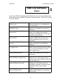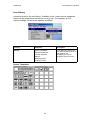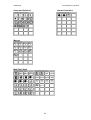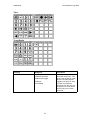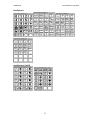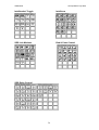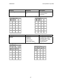
1
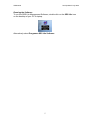
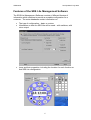
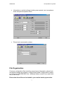
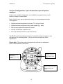
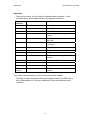
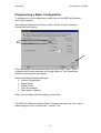
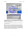
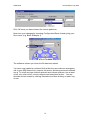
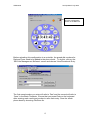
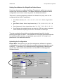
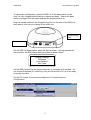
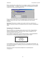
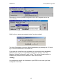
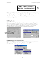
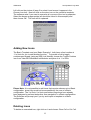
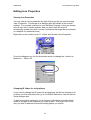
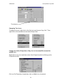
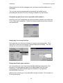
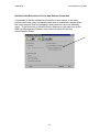
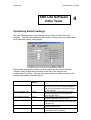
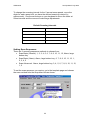
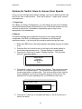
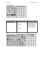
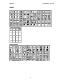
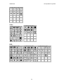
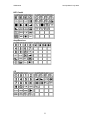
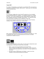
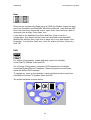
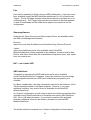
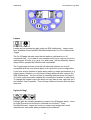
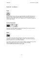
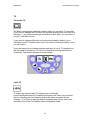
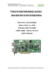
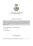
MANAGEMENT SOFTWARE
USER MANUAL
It is important to read and understand this manual before
programming the SRS Lite
SRS Helpline:
01922 459880
SRS Technology Ltd
105 Brickyard Rd
Aldridge
West Midlands
WS9 8SX
Tel. 01922 456882
Fax. 01922 456883
[email protected]
www.srstechnology.co.uk
USM02204
Last Updated: July 2005
Contents
1.
Introduction
3
2.
Programming Configurations
8
3.
Editing Configurations
23
4.
Other Tasks
43
5.
Icons and their Properties
47
6.
A-Z Set-Up List
61
7.
Help
71
2
USM02204
Last Updated: July 2005
SRS Lite Software
Introduction
1
This manual is intended to provide a work-through document for engineers
who are new to the software, as well as providing a reference source of
information for experienced users. If this is the first time you are using the
Software, please work through the document from the Introduction. We also
recommend you read the user manual for the SRS Lite prior to programming if
you are new to the product.
About the SRS Lite Management Software
The SRS Lite Management Software allows you to program the SRS Lite
controller. You can:
•
•
•
•
Create and arrange keypad layouts and LCD submenus
Associate icons with specific device functions. The Software contains
an extensive database of infra-red and radio codes for controlling a
wide range of appliances.
Set scan speeds and the response of the SRS Lite to switch presses to
match the client’s ability
Create a phone book.
When you have completed a configuration you can upload it to the client’s
SRS Lite controller directly. The software retains the configurations allowing
you to update or modify them at a later date.
SRS runs training courses on the SRS Lite Management Software. Please
contact your SRS representative for further details.
Installation
The SRS Lite Management Software is supplied on a CD and utilises
InstallShield for ease of installation.
Requirements for Installation
To run the SRS Lite Management Software you will need a PC/laptop
featuring:
•
Windows 95, 98, ME, NT, 2000 or XP
3
USM02204
•
•
•
•
•
Last Updated: July 2005
A CD-Rom drive
A spare COM port
64Mb Memory
40Mb of free hard disk space
The correct serial uplink cable (SRS Product Code: SUC00301)
Installing the Software
Place the SRS Management Software CD in your CD-Rom Drive. The
installation program will auto-run. If you have auto-run disabled, click on the
Windows Start button and select Run. Browse to your CD-Rom Drive and
select Setup.exe. Click on the OK button.
Follow the on-screen instructions provided by the installation wizard.
Upgrading
In time you may wish to upgrade to future versions on SRS Lite Management
Software. To do this you will need the CD of the version of SRS Lite
Management Software you are currently using. Insert this CD into your CDROM drive and follow the on-screen instructions to remove the SRS Lite
Management Software.
When the removal is complete, put the CD for the newer version of SRS Lite
Management Software into your CD-ROM drive and follow the on-screen
instructions to install the new software.
Please note that any new files you created in the previous version of SRS Lite
Management Software will still be available for use with the new version (i.e.
installing a new version of software does not overwrite files you have created.)
Backup Files
SRS recommends making regular back-up files of Configurations and also of
Device Templates incase anything should happen to your computer. To do
this:
1. Locate your current customer configurations file: Configurations which
is typically found in the following folder
C:\Program Files\SRS\SRS Lite
2. Copy this file to a separate location and rename it to Backup
Configurations
3. Repeat 1 and 2 for the Device Templates folder, also found in
C:\Program Files\SRS\SRS Lite
4
USM02204
Last Updated: July 2005
Running the Software
To run the SRS Lite Management Software, double click on the SRS Lite icon
on the desktop of your PC or laptop.
Alternatively select Programs>SRS Lite Software.
5
USM02204
Last Updated: July 2005
Features of the SRS Lite Management Software
The SRS Lite Management Software consists of different libraries of
information which combine to provide a complete configuration for a
customer. The main databases contain information on:
•
•
The type of configuration – basic or custom
Information on how the SRS Lite will be used – with switches, with
voice output
•
Icons and their properties, including the location for each function on
that SRS Lite configuration
6
USM02204
Last Updated: July 2005
•
Information on switch settings including scan speeds, input acceptance
times and post-acceptance times.
•
Phone book names and numbers
File Organisation
Customer configuration files (including screen layout information, phone book
and switch settings) are stored in a single folder called Configurations located
in C:\Program Files\SRS\SRS Lite. Additional folders contain Icons and Audio
files for the icons.
Ensure that these files are included in your routine back-up procedure.
7
USM02204
Last Updated: July 2005
SRS Lite Software
Programming
Configurations
2
This chapter covers the following aspects to the SRS Lite Management
Software:
•
•
•
•
Design of the 2 programming templates, Basic and Custom
Opening a new customer file and creating a Basic configuration
Opening a new customer file and creating a Custom configuration
Uploading the configurations to the SRS Lite controller
There are two ways in which the SRS Lite can be programmed for use.
These are described below.
Basic Configuration: 14 functions
In this configuration each of the 12 keys on the circumference of the clockface, plus the two large central keys, are programmed to perform a separate
function, bringing the total number of functions that the SRS Lite can be used
for to 14.
Each of the 14 keys can be selected to carry out a pre-programmed task.
This might be:
•
Operate external equipment using infra-red signals (such as a TV)
•
Operate external equipment using radio signals (e.g. door)
•
Dial a pre-programmed telephone number
•
Call the social alarm response unit
When a key is selected, confirmation of the command is shown briefly on the
LCD screen and also announced via the speaker or headphones (volume
must be turned up to hear the announcements).
If the SRS Lite has been programmed for single switch use, it will immediately
recognize if a switch has been plugged in and will then work in scanning
mode – you do not have to make any menu adjustments.
Please Note:
Time delays can be programmed into the software to allow for variations in
switch control between individuals.
8
USM02204
Last Updated: July 2005
When in single switch mode the user can make use of automatic scrolling of
telephone numbers.
When in switch mode you can still operate the SRS Lite using the keys.
Pressing the Lamp key turns
the lamp on/off
Pressing the Mum
key speed dials a
pre-programmed
phone number
Switch users can plug
one or two switches in
here to scan the menu
and select the functions
Operation
Each key will carry out the function illustrated when pressed. In the
example above this means that the keys operate as follows:
Key
Position
Picture
Function
12 o’clock
Smiley Face
Call Carer’s pager
1 o’clock
Phone
Answer/Hang up Phone
2 o’clock
Mum
Speed dial to Mum
3 o’clock
Dad
Speed dial to Dad
4 o’clock
TV
Toggles TV on/off
5 o’clock
Minus
Changes TV Channel Down
6 o’clock
Plus
Changes TV Channel Up
7 o’clock
Down
Turns TV Vol Down
8 o’clock
Up
Turns TV Vol Up
9 o’clock
Hifi
Toggles Hifi on/off
10 o’clock
Lamp
Toggles lamp on/off
11 o’clock
Door
Opens/closes door
Middle top
Social Alarm
Activates social alarm
Middle
bottom
Curtains
Toggles curtains open/closed
9
USM02204
Last Updated: July 2005
Custom Configuration: Up to 96 functions plus 25 phone
numbers
In this more complex configuration, it is possible to programme any key to
perform a single or linked tasks.
Each of the 14 keys can be selected to carry out a pre-programmed task.
This might be:
•
Operate external equipment (such as a TV) using infra-red
•
Operate external equipment using radio signals (e.g. door)
•
Dial a pre-programmed telephone number
•
Call the social alarm response unit
•
Link to a submenu shown on the LCD screen
The SRS Lite will immediately recognize if a switch has been plugged in and
will then work in scanning mode – you do not have to make any menu
adjustments.
Please Note: Time delays can be programmed to allow for variations in
switch control between individuals.
LCD Screen –
showing submenu
of 3 functions for a
DVD
Arrow keys enable
selection of
functions from LCD
screen
Keys programmed to
perform various functions
such as phoning the
Doctor
10
USM02204
Last Updated: July 2005
Operation
Each key will carry out the function illustrated when pressed. In the
example above this means that the keys operate as follows:
Key
Position
Picture
Function
12 o’clock
TV
Make TV submenu Live
1 o’clock
Hifi
Make Hifi submenu live
2 o’clock
DVD
Make DVD submenu live
3 o’clock
Arrow Left
Choose right hand image from LCD
screen
4 o’clock
Carer
Preprogrammed telephone number
for carer
5 o’clock
Doctor
Preprogrammed telephone number
for doctor
6 o’clock
Lamp
Toggle lamp on/off
7 o’clock
Mains Socket
Toggle mains socket on/off
8 o’clock
Fan
Toggle fan on/off
9 o’clock
Arrow Right
Choose left hand image from LCD
screen
10 o’clock
Door
Open/close front door
11 o’clock
Phone
Make Phone submenu live
Middle top
Social Alarm
Trigger social alarm
Middle
bottom
Blank
Choose centre image from LCD
screen
*For each multi-level device, up to 8 functions can be created.
The total number of functions that can be performed by the SRS Lite in
this configuration is 96, plus an additional 25 pre-stored phone book
numbers.
11
USM02204
Last Updated: July 2005
Programming a Basic Configuration
To programme a new configuration double click on the SRS Lite Software
icon on the desktop.
The software loads and presents you with a choice of how to proceed.
Choose the Basic option.
If the user needs voice announcement, then tick Enable Voice. If this
customer will be using switches, tick Single Switch or Two Switches as
required, and choose a scan speed.
Please note that the default setting is:
• Custom Configuration
• Single Switch
• Display Clock
• Voice not enabled
• Scan Speed - Medium
When you are happy with the settings, press Start.
The SRS Lite Software loads the Basic Template and asks you if you want to
make changes to any of the devices. Choose Yes.
12
USM02204
Last Updated: July 2005
The software presents you with a list of the IR Devices included with the
standard Basic template. If you need to change the IR codes for the TV, but
leave the phone and intercom, click Change next to the TV to reveal the full
database of IR codes available.
Use the drop-down boxes to choose the manufacturer and model of the TV
codes you want to use.
Note: You must choose the manufacturer first and allow the management
software time to search for all the available codes from that manufacturer.
The best way to do this is to type the first few letters of the manufacturer into
the field, click the arrow to jump to the correct part of the database, and use
the mouse to highlight and select the manufacturer. When the software has
accepted your input, the cursor will automatically jump to the Model Number
field and you can search to find the model you want.
13
USM02204
Last Updated: July 2005
Click OK once you have chosen the correct appliance.
Now save your changes by choosing Configuration/Save As and giving your
file a name (e.g. Basic Example 1).
The software informs you when the file has been saved.
You have now created a customer file that lets the user make an emergency
call (via an SRS Nurse-Link), answer the phone, dial two pre-stored numbers,
turn a TV on/off and use channel up/down and volume up/down, turn a lamp
on/off, turn a fan on/off, use an intercom and open/close a door. You can
simulate this on screen by clicking Simulation and then clicking on each ‘key’
in turn.
14
USM02204
Last Updated: July 2005
Click Simulation to see
how the configuration
works on the SRS Lite
Before uploading this configuration to a controller, the speed dial numbers for
Dad and Carer need to be added to the phone book. To do this, click on the
‘SRS Lite Management Software’ screen and choose View/Phonebook Entry.
The first name/number you enter will refer to ‘Dad’ and the second will refer to
‘Carer’ in the Basic Template. Ensure that you press Enter on the keyboard
after entering each name and number to save each entry. Save the whole
phone book by choosing File/Save As.
15
USM02204
Last Updated: July 2005
Setting Scan Methods for Single/Dual Switch Users
If you have chosen to configure the Basic Template for switch use, you can
choose from two scan methods. The Basic methods are intended for Basic
configurations, but some users may prefer the Advanced method.
There are 4 scanning sequence methods to choose from (only one can be
configured at the time of installation):
•
Scan Basic (Normal): 12, 1, 2, 3, 4, 5, 6, 7, 8, 9, 10, 11, Alarm, large bottom
key
•
Scan Basic (Alarm): Alarm, large bottom key, 6, 7, 8, 9, 10, 11, 12, 1, 2, 3, 4,
5
•
Scan Advanced: Alarm, large bottom key, 3, 4, 5, 6, 7, 8, 9, 10, 11, 12, 1, 2
•
Scan Display: this method lets the user scan the LCD icons using a separate
switch rather than requiring to use the 3 o’clock and 9 o’clock keys.
To make a selection the switch user simply presses the switch to start
scanning and again to select. A two switch user can either press and hold the
first switch to start scanning, or repeatedly press switch 1 to ‘nudge’, and
press switch 2 to make the selection.
Uploading the Configuration
Please Note: The first time you use the management software to upload a
configuration you will need to define the communications port you wish to use
on the PC. To do this go to Communications/Communication Settings and
use the drop down arrow indicated below on the SRS Lite Management
Software screen:
16
USM02204
Last Updated: July 2005
To upload the configuration, place the SRS Lite in the base station (make
sure it is fully charged before starting to upload any data). Ensure the base
station is plugged into the mains and that the mains power is on.
Plug the upload cable into the Programming Port on the back of the SRS Lite
base station, and into your laptop at the other end.
Programming
Port
Set-up button
On the SRS Lite base station, press the Set-up button. Having pressed the
Set-up button the SRS Lite presents a screen as shown below.
Change Settings
Download
Load Defaults
Run Tests
On the SRS Lite and use the large bottom key to navigate to ‘Download’. Do
not choose Download (3 o’clock key) until you have set the PC up to be ready
to transfer the data.
On the PC choose Communications/Upload to Controller/Upload
Configuration.
17
USM02204
Last Updated: July 2005
Alternatively choose Upload/Configuration from the Template screen as
shown below.
Wait for the on-screen prompt and select Yes when asked.
You have 8 seconds in which to initiate handshaking by pressing the 3 o’clock
key to choose Download on the SRS Lite.
If you want the voice files to be uploaded you can choose these separately
(Upload Voice) or you can upload the configuration and the voice files
together (Upload Configuration with Voice). The Upload Firmware option is
available for potential future releases of SRS Lite firmware.
Note: If you make changes to a configuration with voice, you will need to
choose ‘Upload Configuration with Voice’ when you upload the changes to
ensure that the correct voice files are transferred to the SRS Lite.
Testing
It is important to test all the functions on your SRS Lite to check you have
configured it correctly.
18
USM02204
Last Updated: July 2005
About Icons, Keys, Tiles and LCD Display Representation
Please Note: the SRS Lite Management Software template shows the icons
for each function that can appear on the LCD screen only, and cannot show
the tile you choose for the SRS Lite keypad itself. You may wish to keep a
manual note of this below.
19
USM02204
Last Updated: July 2005
Programming a Custom Configuration
Click the SRS Lite software icon on the laptop.
The software loads and presents you with a choice of how to proceed.
Choose the Custom Configuration option.
If this customer will be using voice announcement, then tick Enable Voice. If
this customer will be using switches, tick Single Switch or Two Switches as
required, and choose a scan speed (Medium is highlighted by default).
When you are happy with the settings, press Start.
The SRS Lite Software loads the blank Custom Template and asks you to
type in the name of the file.
You can now import any icon from the Available Icons directory to create a
custom configuration.
The process of importing codes for a TV is illustrated below.
20
USM02204
Last Updated: July 2005
On the Available Icons page, select the image of the TV then click on the
location of the custom template where you wish the TV functions to appear.
The software asks if you wish to use a pre-configured template of TV
functions (there are 4 to choose from).
As described with the Basic Configuration, use the drop-down boxes when
prompted by the software to choose the manufacturer and model of the TV.
Click OK once you have chosen the correct make and model of appliance.
To see how the Custom configuration works, choose Simulation from the
screen below, and then click on each key in turn to see how the configuration
works.
21
USM02204
Last Updated: July 2005
Before uploading this configuration to a controller, numbers should be added
to the phone book. To do this, click on the SRS Lite Management Software
screen and choose View/Phonebook Entry.
Ensure that you press Enter on the keyboard after entering each name and
number to save each entry. Save the whole phone book by choosing
File/Save.
Important: Enter phone numbers in the order in which you wish them to
appear in the phone book as the software does not put entries in alphabetical
order.
Uploading the Configuration
Place the SRS Lite in the base station (make sure it is fully charged before
starting to upload any data). Ensure the base station is plugged into the
mains and that the mains power is on.
On the SRS Lite base station, press the Set-up button. Having pressed the
Set-up button the SRS Lite presents a screen as shown below.
Change Settings
Download
Load Defaults
Run Tests
On the SRS Lite and use the large bottom key to navigate to ‘Download’. Do
not choose Download (3 o’clock key) until you have set the PC up to be ready
to transfer the data.
On the PC choose Communications/Upload to Controller/Upload
Configuration.
22
USM02204
Last Updated: July 2005
Alternatively choose Upload/Configuration from the Template screen as
shown below.
Wait for the on-screen prompt and select Yes when asked.
You have 8 seconds in which to initiate handshaking by pressing the 3 o’clock
key to choose Download on the SRS Lite.
If you want the voice files to be uploaded you can choose these separately
(Upload Voice) or you can upload the configuration and the voice files
together (Upload Configuration with Voice). The upload firmware option is
available for potential future releases of SRS Lite firmware.
Testing
It is important to test all the functions on your SRS Lite to check you have
configured it correctly.
23
USM02204
Last Updated: July 2005
SRS Lite Software
Editing Configurations
3
The Basic and Custom templates provided by the Management Software are
suitable for many circumstances, but there will be times when you need to edit
a configuration to accommodate different equipment, different icons or
different locations for each task. This chapter explains how to edit and
customise configurations.
Editing Icons
Start by opening the file ‘Basic Example 1’, which you created in Chapter 2.
You can find this file quickly by clicking on Load Existing Configuration/Start
when you first start the SRS Lite Management Software or by choosing
File/Open Existing Configuration if you are already in the software.
Example: replace door with second lamp.
Click on the SRS Lite template to bring it to the front of your computer screen.
Then go to the Available Icons library and choose ‘View/SRS
Modules/Intellisocket Toggle’ to see the choices available.
24
USM02204
Last Updated: July 2005
Left click on the picture of lamp 2 to select it and ensure it appears in the
Chosen Icon box. Now left click on the door icon on the controller template.
The software asks if you want to overwrite all or some of the icon’s properties.
Select the boxes as appropriate (all should be ticked in this example) and
then choose OK. The icon will be replaced.
Adding New Icons
The Basic Template and your Basic Example 1, both have a free location at
11 o’clock for you to add another function. To provide a link to toggle
curtains open/closed (using an SRS Link Module) choose the Toggle Curtains
icon from View/SRS Modules/Link Modules and place it at 11 o’clock.
Please Note: It is not possible to add icons that require submenus to a Basic
configuration, since they would not be accessible by the user of a Basic
configuration. The 3 o’clock, 9 o’clock and bottom large keys have already
been assigned to perform tasks other than navigation in a Basic configuration.
The Software will prompt you if you try and import a template to a Basic
configuration.
Deleting Icons
To delete an unwanted icon, right click on it and choose Clear Cell or Cut Cell.
25
USM02204
Last Updated: July 2005
Editing Icon Properties
Viewing Icon Properties
You can view an icon’s properties by right clicking on the icon and choosing
View /Properties. This brings up a dialogue box with details of the current
settings. For example, assume on your file Basic Example 1 that you already
have a user with a curtain operator and you don’t wish this client to
accidentally operate the other’s curtain (a situation that might be encountered
in a hospital or residential home).
Right click on the curtain key at 11 o’clock and choose View /Properties.
From the dialogue box, use the drop-down arrow to change the Location to
Bedroom 1. Select OK.
Changing IR Codes for an Appliance
If you need to change the IR codes for an appliance, but did not choose to do
so when you first opened the file, go to Tools/Edit Devices to view the Device
Setup dialogue box.
To edit icons within a submenu (on a Custom configuration) use Simulation
mode to navigate to the submenu you wish to alter. Then right click on the
icon you wish to edit and choose the editing option you require.
26
USM02204
Last Updated: July 2005
Programming Advanced Functions
The Basic Programming wizard make it quick to set up a configuration. You
may find that further customization is needed to provide a perfect solution for
an individual. The tasks below can be used on basic and custom
configurations.
This section describes how to:
- Skip unpopulated icons
- Swap two icons
- Change the action properties of any icon to
increment/decrement the middle icon
- Overwrite any part of an icon’s properties with another’s
- Assign any icon to any function
- Design and create new icons
- Send a 2,3 or 4 digit IR command
- Assign IR sticky to any IR Send action and adjust the
transmission interval
- Send IR on press and release of key
- Assign voice tags to icons
- Delete voice tags on icons
- Optimise voice memory
- Assign house codes to RF devices
- Control individual Relay Functions in SRS RF Devices
- Create and run a Macro
- Use Multi-Digit Send within a macro
- Use system control within a macro
- Set up custom screens
- Set brightness control for the backlight
- Start submenu scanning on selection of a device
- Go back to top after key press and release
Skipping Unpopulated Icons
Where you are not populating all keys on the SRS Lite, you may wish the
highlighter to skip past the unused keys. In this case you will need to do the
following:
On the SRS Lite Management Software screen, click on View and then on
Controller Input Settings.
Tick the box titled Do Not Scan Unpopulated Icons (shown below) if you do
not require the controller to scan unpopulated keys.
27
USM02204
Last Updated: July 2005
Tick this box
Swapping Two Icons
To swap two icons, right click on the first icon and choose Copy Cell. Then
right click on the second icon and select Swap Cells.
Change the Action Properties of Any Icon to Increment/Decrement the
middle icon
Right click on any icon and then select View Properties which will bring up the
Properties screen.
Click on Set Properties As and then click on Middle Icon Increment.
28
USM02204
Last Updated: July 2005
Selecting the icon with the changed action will now cause the middle icon to
increment.
The icon can also be programmed to decrement the middle icon by
proceeding as above but this time clicking on Middle Icon Decrement.
Overwrite any part of one icon’s properties with another’s
Import an icon over a populated cell and the software prompts you to alter any
or all of that icon’s properties. Select only those properties you wish to import
and choose OK.
Assign any icon to any function
First import the icon with the functions you require into the template. Then
right click on that icon and choose Change Property/Icon Bitmap. You can
choose any icon from the available list.
Design and Create your own Icon
You can create your own icons using the Microsoft Paint programme. Run
Microsoft Paint and load the blank icon file Blank.BMP from the icons
subdirectory of the SRS Lite Management Software (C:\programme
files\SRS\SRS Lite\Icons).
Edit the icon, ensuring you only draw within the given border. Do not adjust or
fill the outside area.
29
USM02204
Last Updated: July 2005
Click on File/Save As when you have completed the drawing, and save the
image in the same subdirectory as Blank.BMP. You can import the new icon
to any location by right-clicking on the imported icon and choosing Change
Property/Icon Bitmap as before. This time select the icon you have created.
Send a 2, 3 or 4 Digit IR Command
The first step is to create an icon that will perform the multi-digit IR command.
Click View on the Available Icons screen and then System and Multi Digit
Send.
Choose one of the icons e.g. Sky 1
Click on the icon on your SRS Lite template where you want the multi-digit
send command to go (this can be an empty location or you can overwrite an
existing icon); you will then be presented with the screen titled Device
Selection, shown below:
Select either New Device or Use Existing Device as appropriate.
30
USM02204
Last Updated: July 2005
If you choose New Device you will be presented with a screen titled Add a
Device. Now insert the manufacturer, model and serial number of the device
to which you wish to send a 2, 3 or 4 digit code.
If you choose Use Existing Device you have the option to select the device
from the drop-down list of devices in the customer file. Select OK once you
have chosen the correct device.
Right click on the required icon (in non simulation mode) and then select View
Properties as shown below:
Click on Set Properties as to reveal the drop-down list shown
31
USM02204
Last Updated: July 2005
Click on IR Digit Sender; you will then be presented with a screen titled
Device Selection
Select either New Device or Use Existing Device
You are then presented with a box titled Infrared Digit Sender to enter the
required multi-digit code:
Type in the code you want the icon to send e.g. 567 as shown.
Assign IR sticky to any IR Send action and adjust the transmission
interval
IR Sticky enables the IR signal to be sent continuously upon selection of a key
and only to be stopped when the key is selected again (useful for TV functions
such as ‘channel up’ where the user may want to scroll through the channels
to find something suitable to watch.
IR sticky can be assigned to any IR send action by right clicking on the icon,
then choosing Change Property/Sticky IR Delay. The transmission interval
can be input in milliseconds between 100 and 25,500 (i.e. 0.1 – 25.5
seconds).
Send IR on press and release of key
This function allows 2 different IR signals to be sent upon selection of a single
key – the first signal is sent when the key is pressed and the second is sent
when the key is released. First import the icon with the IR properties you
want to use on the key press. Now right click on the icon and choose Change
Property/IR Release Button. Type in the Device Button Number required –
value between 0 and 31 (e.g. 0 = Channel 0; 1 = Channel 1 etc).
32
USM02204
Last Updated: July 2005
Assigning Voice Tags to or Deleting Voice Tags from Icons
To assign a voice tag to an icon, first right click on that icon and select
Change Property/Voice Tag. The software presents a scroll-down choice of
all the pre-recorded voice tags that are available to choose from.
To delete a voice tag from an icon, right click on that icon and select Delete
Property/Voice Tag.
Optimising Voice Memory
In order to create more memory for functions it is possible to clear the
memory allocated to voice files that are not required. To do this choose
Tools/Optimise Voice Memory from the SRS-Lite Configuration page and
follow the instructions.
33
USM02204
Last Updated: July 2005
Assigning House Codes to RF Devices
‘House Codes’ are used to differentiate SRS systems between users who are
within signal reach of each other. By choosing different house codes for the 2
configurations, the radio equipment will be assigned different signal properties
to ensure the systems only operate the equipment in one house, not that of
the next door neighbour as well.
From the SRS Lite Management Software page choose View/Communication
and Controller Settings. Select the House Code Number required.
House Code Number
Controlling Individual Relay Functions in SRS RF Devices
If you need to have control of individual relays in SRS RF devices such as the
SRS Relay (for example if you are configuring it for use with a profiling bed),
first import the appropriate icon onto the template. Now right-click on the icon
and select View Properties. From the Properties box choose Set Properties
As/Bed Chair and Channel Control.
34
USM02204
Last Updated: July 2005
The software displays a choice of options for configuring the individual relay
functions as shown. Select the required configuration and choose OK.
Create and run a Macro
With the SRS Lite you can programme a string of functions linked to a single
key/switch selection (macro); each macro can be programmed to have 12
functions (from 12 o’clock through to 11 o’clock)
a.
Simple Macro
A simple macro will link functions to a single selection where the functions will
be set to occur sequentially
Open client file screen SRS Lite Configuration File Name <…>
Select View on the Available Icons screen and then Systems followed by
Macros
35
USM02204
Last Updated: July 2005
Click on any of the icons shown on the System (Macros) screen (e.g. Macro
1) and this will appear in the chosen icon window;
Click on the chosen location on the template of the client screen; you will then
be presented with the screen titled Macro Name.
Enter the name of your macro (e.g. ANSWER PHONE) and click OK.
You will then be presented with a blank template to populate the functions you
wish to link into a macro.
Populate the template in the same way as you would when configuring the
SRS Lite for the first time.
Example
You want to mute TV, switch on the light and answer the telephone in one
operation
Select View on the Available Icons screen and then System followed by
Macros
Continue as above; when prompted for the name of the macro enter
ANSWER PHONE; press OK.
36
USM02204
Last Updated: July 2005
Select View from Available Icons and then TV, Satellite, Video, etc; select TV
icon (confirm by checking Chosen Icon window);
Select the mute icon from the current TV screen within Available Icons that
you have navigated the user to.
Click on the 12 o’clock location; you will then be prompted with the screen
titled Device Name; follow the prompts to insert the make and model of the TV
to be muted; press OK
Check (mute) icon has appeared in the 12 o’clock location;
Click on View and then SRS Modules and then select the Intellisocket toggle;
click on lamp icon (confirm by checking Chosen Icon window);
Click on the 1 o’clock location and confirm that the Lamp icon has appeared in
this location.
Click on View and then SRS Modules and then select the Intelliphone; click on
the Lift Handset telephone icon.
Click on the 2 o’clock location and confirm the Lift Handset Telephone icon
has appeared at this location
Select Simulate and the main screen will appear with the Macro 1 icon at 2
o’clock; click on Macro 1 to read Running Macro Answer telephone
Note: when programming the macro the three functions selected will run
consecutively
37
USM02204
b.
Last Updated: July 2005
Delay Macro
Select the delay macro function when you want to include a delay between
each of the functions.
To programme a ‘delay macro’ open the macro template (or create a new one
as explained above);
Select View in the Available Icons and then Systems followed by Macros;
Click on the Macro Delay icon; place the Macro Delay icon in the 12 o’clock
position; you will then be presented with the screen titled Macro Pause
Period;
Type in the duration of the pause you require between 500 and 64,000
milliseconds; click OK and the Delay Macro icon will appear in the 12 o’clock
location.
Note: The programmed time interval of the pause delay is the same between
all functions making up the macro
In the above example continue to insert the mute, light on and lift handset
icons in 1, 2 and 3 o’clock locations respectively.
Select Simulate and the main screen will appear with (Macro 1) icon at 2
o’clock; click on (Macro 1) icon to read the individual functions with the
chosen pause delay.
c.
Loop Macro
Select a loop macro when you want to run a macro repeatedly.
38
USM02204
Last Updated: July 2005
To programme a loop macro, select View in the Available Icons and then
System followed by Macros;
Click on Loop Macro icon, which appears in the Chosen Icon window
Select the location (from 1 o’clock to 11 o’clock) where you want to position
the Loop Macro icon and click; the icon will appear in that location.
Selecting the macro will mean the SRS Lite will repeatedly transmit the
sequence of commands corresponding to the functions located between 12
o’clock and the position of the Loop Macro icon.
d.
Change any icon to become a Macro
If you want to change an icon to become a macro:
Right click on that icon and then click on View Properties; you will then be
presented with the screen titled Properties;
Click on Set Properties As and then choose Macro; you will then be presented
with the screen titled Macro Name;
Enter the name of your macro and click OK;
Proceed as in a. above.
Using Multi-Digit Send within a Macro
Set up your macro using the instructions above and, where multi-digit send is
required, click on View in the Available Icons form and choose System/MultiDigit Send.
39
USM02204
Last Updated: July 2005
Import the Multi-digit send icon into the macro template at the end of the digit
sequence you wish to send.
The software asks you to type in the digits you wish to use, and also which
appliance’s codes to use.
Using System Controls within a Macro
Set up your macro using the instructions above and, where a system control
(such as screen brightness control, scan speed or volume control) is required,
click on View in the Available Icons form and choose System/Setup and
Switches. Import the required icon into the template.
Creating Custom Screens
To create your own custom screen click on View in the Available Icons screen
then on System and Custom Screens. (Note: this is only possible with
Custom Configuration templates).
Click on any of the Custom icons e.g. Custom 1 icon. This will then appear in
the Chosen Icon window. Click on any location on the template and the
Custom Screen Name screen will appear.
40
USM02204
Last Updated: July 2005
Type in the name (e.g. BEDROOM) and click OK.
A custom page is created for you to populate with your chosen functions.
Setting Backlight Brightness
To set the brightness of the backlight, go to View/Execution Settings in the
SRS Lite Management Software form. Adjust the slider in the Backlight
Settings section (0% is no backlight and 100% is full power). The default
setting is ‘auto’ where the backlight strength increases as the ambient light
decreases.
Start Scanning the Submenu on Selection of a Device
It is possible to set the software to immediately start scanning the submenu of
a chosen device (rather than the alternative option which requires the user to
press the key again). To set this click on View/Execution Settings on the main
form of the SRS Lite Management Software form. Select the box Start
Scanning on Device Selection.
41
USM02204
Last Updated: July 2005
Go Back After Execution of Press and Release Command
It is possible to set the software such that the cursor returns to the start
position each time a key is pressed (rather than the alternative option where
the cursor stays on that key awaiting further instruction such as submenuscan). To set this click on View/Execution Settings on the main form of the
SRS Lite Management Software form. Select the box Go Back on
Press/Release Action.
42
USM02204
Last Updated: July 2005
SRS Lite Software
Other Tasks
4
Optimising Switch Settings
The Input Settings part of the software can be found at View/Controller
Settings. This part of the software allows you to change the input parameters
for a particular client’s configuration.
Before making changes, ensure you are working on the correct client file
(choose View/Configuration and look at the top of the page for the
configuration file name). Use the drop down arrows to make changes to the
settings described in the table below.
Setting
Default
Setting
Description and Use
Input Device
Direct Access
Input Acceptance Time
100ms
Post Acceptance Delay
100ms
Hold Time Discriminator
200ms
Pause On First Item
2 Times
Maximum Scan Loops
2 Times
Default and initial selection of input device.
Users may, at any time, change to a single or
dual switch input simply by plugging the switch
into the SRS Lite.
Minimum length of time that a key must be
pressed for the SRS Lite to recognise the
action as a key press.
Delay between a key press and the initiation of
any action required by the key press.
Maximum length of time allowed before two
clicks are treated as separate clicks rather than
a double click.
Number of scan delay cycles that the SRS Lite
passes on the first icon.
Maximum number of scan cycles that the SRS
Lite completes before stopping.
43
USM02204
Last Updated: July 2005
To change the scanning interval for the 5 pre-set scan speeds, move the
slider for each speed until you have the desired scanning interval (in
milliseconds). Use the arrow keys on your keyboard to move the slider at
50ms intervals and the mouse to make large adjustments.
Default Scanning Intervals
Fastest
100 ms
Fast
500 ms
Medium
1000 ms
Slow
1750 ms
Slowest
2000 ms
Setting Scan Sequences
There are 3 scanning sequence methods to choose from:
• Scan Basic (Normal): 1, 2, 3, 4, 5, 6, 7, 8, 9, 10, 11, 12, Alarm, large
bottom key
•
Scan Basic (Alarm): Alarm, large bottom key, 6, 7, 8, 9, 10, 11, 12, 1,
2, 3, 4, 5
•
Scan Advanced: Alarm, large bottom key, 3, 4, 5, 6, 7, 8, 9, 10, 11, 12,
1, 2
To set the scan sequence you require, go to the template page and choose
the scan method from the drop-down box as shown.
44
USM02204
Last Updated: July 2005
Options for Switch Users to choose Scan Speeds
Once you have configured the switch settings, you need to determine the best
way for the user to access them. There are 3 options – single icons, manual,
and submenus.
1. Single Icon
On a Basic or Custom Configuration, you can assign an icon (from Available
Icons/View/System/Setup and Switches) to any of the Scan Speeds, but this
will take up one of the 14 available key positions and so may not be
appropriate in all installations.
2. Manual
The switch settings can be adjusted at any time (over-riding settings
configured in the SRS Lite Management Software) by following the
instructions below. It is likely that this would be carried out by the carer.
1. Place the SRS Lite in the base station and press any key to wake
it up.
2. Press the Set-Up Control button on the back of the base station to
reveal the programming menu. ‘Change Settings’ is highlighted.
3. Press the 3 o’clock key to select ‘Change Settings’. This reveals a
submenu as shown below:
Scan Speed
Speech
Backlighting
Time
4. Press the 3 o’clock key to choose Scan Speed. This reveals a screen
on the LCD as shown below. The number at the right will show the
current scan delay in milliseconds. This is the amount of time that the
cursor highlights one function key before moving to the next (in this
example it is currently spending 2.5s (or 2500ms) on each icon.
Scan Delay (ms)?
2500
5. Press the 3 o’clock key to increase the delay, or the 9 o’clock key to
reduce the delay.
45
USM02204
Last Updated: July 2005
6. When the correct value is showing on the LCD screen, press the large
bottom key on the SRS Lite to accept the value and exit back to the
set-up menu.
7. Use the large bottom key to highlight Exit and the 3 o’clock key to
escape back to the main SRS Lite menu.
3. Submenu
The full set-up submenu can be made available to users by choosing the
Custom Configuration template and assigning the Set-Up icon (shown below)
from Available Icons/View/System/Device Templates to one of the keys on the
SRS Lite keypad. This gives the user access to an LCD submenu of preprogrammed scan speeds.
Set-up Icon
Set-up Submenu on LCD
46
USM02204
Last Updated: July 2005
SRS Lite Software
Icons
5
Icons in the SRS Lite Management Software are found in the Available Icons
library and can be classified according to their properties. There are 10 types
of icon as follows:
Linking Icons
Cause a submenu to be displayed on
the LCD screen
Navigation Icons
Allow you to navigate into layers of a
submenu
Set-up Icons
Allow you to adjust some internal
settings on the SRS Lite such as scan
speeds and backlighting
Speech Icons
Cause the SRS Lite to announce a
word or phrase but not to carry out
any action
IR Icons
Send an IR signal to a predefined
appliance
IR Toggle Icons
Send first one IR signal and then other
(e.g. to turn the TV both on and off
from a single icon)
Radio (473MHz) Icons
Send a radio signal (e.g. to a nursecall alarm)
Radio (473MHz) Toggle Icons
Send first one radio signal and then
another (e.g. to turn a lamp on then off
from a single icon)
Radio (473MHz) Fail Icons
Displays on LCD screen only (not
available in software) to alert user that
radio signal did not reach target
device
Radio (173MHz) Icons
Sends a radio signal to a community
alarm device
47
USM02204
Last Updated: July 2005
Icon Library
Icons are stored in the icon library “Available Icons” under various categories
based on the properties of all the icons in a group. For example, all the
system settings can be found together as shown:
Category
Subgroup
Description
System
Device Templates
Setup and Switches
Internal Operation
Macros
Multi-Digit Send
Custom Screens
Icons that link to submenus,
or to internal settings such as
scan speeds and
backlighting, or are for
navigation around a menu.
Device Templates
48
USM02204
Last Updated: July 2005
Setup and Switches
Internal Operation
Macros
Multi Digit Send
49
USM02204
Last Updated: July 2005
Custom Screens
Category
Subgroup
Description
TV, Satellite, Video etc
TV
Satellite
Cable/Freeview
Video
DVD
Hifi Combi
Amp Receiver
CD
Tape
Tuner
Icons that perform individual
tasks for appliances (e.g. TV
standby), but do not link to
submenus. Use these on
basic configurations or to
customise submenus on
complex configurations.
TV
50
USM02204
Last Updated: July 2005
Satellite
Cable/Freeview
51
USM02204
Last Updated: July 2005
Video
DVD
52
USM02204
Last Updated: July 2005
HiFi Combi
Amp/Receiver
CD
53
USM02204
Last Updated: July 2005
Tape
Tuner/Radio
Category
Subgroup
Description
SRS Modules
Intelliphone
Intellisocket On/Off
Intellisocket Toggle
Intellicom
Link Module
Icons that have properties to
drive SRS equipment. The
phone uses IR signals, other
devices use radio signals.
Toggle icons send ‘on’ then
‘off’ radio commands in
sequence from the one icon
as opposed on on/off which
perform only one or other
command
54
USM02204
Last Updated: July 2005
Intelliphone
Intellisocket On/Off
55
USM02204
Last Updated: July 2005
Intellisocket Toggle
Intellicom
SRS Link Modules
Bed & Chair Control
SRS Relay Control
56
USM02204
Last Updated: July 2005
Category
Subgroup
Description
Community Alarm
Tunstall
BT
Icons that operate named
community alarm
equipment.
Tunstall
BT
Category
Subgroup
Description
Speech
Emergency
Food/Drink
Personal Care
Family and Friends
Icons that carry voice data
commands, but no IR/
radio properties. These
icons are for basic
communication.
Emergency
Food and Drink
57
USM02204
Last Updated: July 2005
Personal Care
Family and Friends
58
USM02204
Last Updated: July 2005
Category
Subgroup
Description
3rd Party Devices
Possum Phone/Intercom
Possum Socket
Curtains and Blinds
Light Dimmers
Icons for operating third
party equipment.
Possum Phone/Intercom
Possum Socket
Possum Bed
Gewa Duocom
59
USM02204
Last Updated: July 2005
Curtains Blinds and Windows
Dimmers
60
USM02204
Last Updated: July 2005
SRS Lite Software
A-Z Setup List
6
This section contains instructions for configuring specific devices using the
SRS Lite Management Software. For details on configuring device hardware
such as SRS Link Modules or X10 modules, refer to the manufacturer’s
instructions for those devices.
The following installations are described:
Alarms
Blinds
Combi HiFi
Community Alarm (see Alarms)
Curtain
Door
DVD
Fan
Gewa appliances
HiFi
SRS Intellicom 106, 108 or 280
Lamps
Light Dimmer
Nurse-call
Pager
Possum Equipment
Radio
Telephone
TV (terrestrial, cable, satellite)
Video
61
USM02204
Last Updated: July 2005
Alarms
Nurse-link
The default Basic configuration assumes the Alarm used is an SRS NurseLink module. Selection of the Alarm (LCD icon pictured above) triggers the
SRS Nurse-Link which requires the nurse to turn the siren off.
It is possible to provide the user with an ‘Alarm cancel’ function. To do this,
import the Nurse-call Cancel icon from Available Icons/View/SRS
Modules/Link Module into your configuration.
If you are creating a custom configuration and wish to use the Nurse-call
Alarm and Cancel functions, then import these from Available Icons/View/SRS
Modules/Link Module
Community Alarm
The SRS Lite can be configured to drive Tunstall community alarm equipment
at 173MHz and BT infra-red community alarm equipment. Choose the
appropriate icons from Available Icons/View/Community
Alarm/(manufacturer).
Important: Please note that at the time of writing, the SRS Lite is not an
approved trigger device (as there are no standards for testing environmental
control equipment in these circumstances). SRS therefore recommends that
a community alarm function on the SRS Lite should not be the only means of
calling for help in an emergency.
Blinds
Individual icons to drive Infra-red blinds can be found in Available
Icons/View/3rd Party Devices/Curtains and Blinds. Import the icon and, when
prompted, use the drop-down boxes to specify the manufacturer and model of
blind operator you are using.
62
USM02204
Last Updated: July 2005
Combi HiFi
For a Basic Configuration you will need to use individual HiFi commands from
Available Icons/View/TV Satellite Video etc/HiFi. Import each icon individually
to the preferred location.
For a Custome configuration, import the HiFi template icon from Available
Icons/View/System/Device Templates. The software prompts you to assign
IR codes. If you need to change any of the default icons then choose them
from Available Icons/View/TV Satellite Video etc/HiFi. The correct IR codes
will automatically be assigned from the database if they exist.
The default HiFi template (LCD: Record, Play Stop; Keys: Next, Previous,
Standby, Volume Down, Volume Up) is shown below:
More complex stacking HiFi systems can be operated by the SRS Lite – icons
for separate tuner, amp, CD and tape decks can be found in Available
Icons/View/TV Satellite Video etc.
Curtain
Curtains can be operated in various ways. You will need to choose the correct
icon dependent on the way the curtain will be controlled.
•
By IR – import icons from Available Icons/View/3rd Party
Devices/Curtains and Blinds and, when prompted, use the drop-down
boxes to specify the manufacturer and model of IR curtain operator you
are using.
•
By Radio using an SRS Curtain-Link Module – import icons from
Available Icons/View/SRS Modules/Link Module
63
USM02204
Last Updated: July 2005
Door
Doors can be controlled by Radio using an SRS Link Module. Import the door
icon from Available Icons/View/SRS Module/Link Module. Note that the SRS
Door-Link module by default will unlock, open, hold, close and lock a door in
sequence from a single ‘Door Open’ icon.
If you wish to use separate Door Open and Door Close icons for a
configuration, then import the two icons from Available Icons/View/SRS
Module/Link Module. Next, right click on each icon in turn and choose View
Properties. For the Door Open icon, click ‘On’ and for the Door Close icon,
click ‘Off’.
DVD
For a Basic Configuration, import individual icons from Available
Icons/View/TV Satellite Video etc/DVD.
For a Custom Configuration, import the DVD template from Available
Icons/View/System/Device Templates. When prompted by the software,
import the default DVD template.
To change any icons on the template, import individual function icons from
Available Icons/View/TV Satellite Video etc/DVD.
The default template is shown below:
64
USM02204
Last Updated: July 2005
Fan
Fans can be operated by Radio using an SRS Intellisocket – import fan icons
from Available Icons/View/SRS Modules/Intellisocket On Off or Intellisocket
Toggle. The On Off page includes icons that will perform individual on or off
commands only. The Toggle page includes icons that will alternate between
on and off commands and are used where space is at a premium on the
configuration.
Gewa appliances
Codes for the Gewa Duocom and Gewa Jupiter Phone are available within
the SRS Lite Management Software.
Duocom:
Import the icons from Available Icons/View/third Party Devices/Duocom.
Jupiter:
Import the Intelliphone icons from Available Icons/View/SRS
Module/Intelliphone. When prompted by the software, choose to add a ‘New
Device’ and select Gewa from the manufacturer drop-down menu, and Jupiter
from the model menu.
HiFi – see Combi HiFi
SRS Intellicom
Templates for operating the SRS Intellicoms are found in Available
Icons/View/System/Device Templates. Import the intercom icon and assign
the appropriate manufacturer (SRS) and model when prompted by the
software.
In a Basic configuration, the main commands required for an Intellicom 106 or
108 are already included in the Basic template. However, if you need
additional functions, they can be found in Available Icons/View/SRS
Modules/Intellicom.
In a Custom configuration you will need to import the Intellicom template from
Available Icons/View/System/Device Templates and specify SRS Intellicom
280, 106 or 108 when prompted. If you need to customise the standard
template, additional icons can be found in Available Icons/View/SRS
Modules/Intellicom.
The default Intellicom template for a Custom configuration is shown below:
65
USM02204
Last Updated: July 2005
Lamps
Lamps can be operated by radio using an SRS Intellisocket – import icons
from Available Icons/View/SRS Modules/Intellisocket On Off or Intellisocket
Toggle.
The On Off page includes icons that will perform individual on or off
commands only. If you want to use separate on/off icons, ensure you pick a
matching pair of icons (e.g. Lamp 1 on and Lamp 1 off) as differently named
lamps will be operated by different radio commands.
The Toggle page includes icons that will alternate between on and off
commands and are used where space is at a premium on the configuration.
If you have a large number of lamps being used in a single environment (e.g.
nursing home, hospital), you will need to assign different radio codes to the
SRS Intellisockets. You can do this by choosing different icons for Lamps 14. Further codes are made available by choosing the ‘location’ of each lamp.
To change the location import the lamp icon you want to use, right click on it
and choose View Properties. Then choose a different location with the dropdown box.
Lights (Ceiling)
Ceiling Lights are usually operated by means of an IR dimmer switch. Icons
for Light Dimmers can be found in Available Icons/View/3rd Party
Devices/Dimmers. Import the icons you require and assign the correct
manufacturer and model when prompted by the software.
66
USM02204
Last Updated: July 2005
Nurse-call – see Alarms
Pager
Use the default Nurse-Link icons (from Available Icons/SRS Modules/Link
Modules) when programming the SRS Lite, but instead of wiring the Link
module to a Nurse-call, wire it to the Pager device. No separate Pager icon
exists in the software.
Possum Equipment
Individual icons with codes to operate the Possum Phone can be found in
Available Icons/View/3rd Party Devices.
Radio
If the radio is part of a combi Hifi system, the radio icon can be found in
Available Icons/View/TV Satellite Video etc/HiFi. You can use this icon in
place of another icon on the default template.
If you want to simply turn a radio on and off using an Intellisocket (e.g. for a
Basic Configuration) then import a Socket icon from Available
Icons/View/SRS Modules/Intellisocket Toggle.
67
USM02204
Last Updated: July 2005
Telephone
With a Basic Configuration, the IR codes to drive the SRS Intelliphone are
included with the standard template. You can add additional icons and
speed-dial commands by choosing icons from Available Icons/View/SRS
Modules/Intelliphone.
With a Custom Configuration, you can add additional icons and speed-dial
commands by choosing icons from Available Icons/View/SRS
Modules/Intelliphone.
If you are starting from a blank template, and want to use a template-based
phone configuration, then first import the Phone icon from Available
Icons/View/System/Device Templates, and then assign the correct IR codes
when prompted by the software. If you only need a few icons, then go straight
to Available Icons/View/SRS Modules/Intelliphone to select individual
commands and assign the IR codes.
Phone Book:
The phone book can store up to 25 names and numbers in the Custom
Configuration. They can be accessed by using speed-dial icons, or by using a
text-based menu (the latter requiring Custom Configuration template).
Numbers are displayed in the order in which they are entered into the
database, not in alphabetical order.
To enter a number into the phone book, first ensure you have the correct
configuration file open. Then choose View/Phonebook Entry to enter names
and numbers. Ensure that after typing each name and number in you press
Enter to save the entry.
If you are planning to use a large number of speed-dial icons, it is best to
enter the names and numbers into the phone book first and then import the
icons, as the software prompts you to assign numbers to each icon as it is
imported.
68
USM02204
Last Updated: July 2005
TV
Terrestrial TV
The Basic configuration template contains codes for terrestrial TV operation.
If you need to change the IR codes, the software prompts you to do this as a
first step. If you choose to change IR codes at a later point, you will need to
choose Tools/Edit Device.
If you need to choose different icons to those provided by default, go to
Available Icons/TV Satellite Video etc/TV to see the individual function icons
you can import.
If you are starting from a blank template and wish to use a TV template you
will first need to choose the TV icon from Available Icons/System/Device
Templates. The default template is shown below.
Cable TV
To import the default Cable TV template go to Available
Icons/View/System/Device Templates and import the Cable icon (pictured
above), choosing the manufacturer and model when prompted by the
software. If you wish to alter the default template then choose icons from
Available Icons/View/TV Satellite Video etc/Satellite Cable.
69
USM02204
Last Updated: July 2005
Satellite TV
To import the default Satellite TV template go to Available
Icons/View/System/Device Templates and import the Satellite icon (pictured
above), choosing the manufacturer and model when prompted by the
software. If you wish to alter the default template then choose icons from
Available Icons/View/TV Satellite Video etc/Satellite Cable.
Video
To import a Video and template for a Custom Configuration, go to Available
Icons/View/System/Device Templates and choose the Video icon, selecting
the manufacturer and model when prompted. The default template is
illustrated below.
If you need individual video functions they can be found in Available
Icons/View/TV Satellite Video etc/Video.
70
USM02204
Last Updated: July 2005
SRS Lite Software
Help
7
Solutions for some common programming problems are detailed below:
Problem
Solutions
Can’t upload any data to SRS Lite
Check SRS Lite is fully charged, that it is secure in the
base station and that the mains power is on. Check all
cable connections between PC and SRS Lite.
Ensure you have selected an available COM port in the
software (see page 16).
SRS Lite doesn’t function in the
intended manner.
Check all icon properties on your software template (by
right clicking on each and choosing View Properties) and
amend any errors by importing the correct icon or revising
the properties of the one on the template.
For SRS radio devices, ensure the device itself is cloned
correctly.
No voice sounds from the controller.
Check that you have uploaded the voice files. Check that
the loudspeaker volume is turned up on the SRS Lite.
Single switch mode doesn’t work.
Check that you assigned single switch mode to the
configuration file and that you have uploaded the file
correctly. Check that the switch you are using is fully
plugged in and is not broken (e.g. by testing on another
device).
Can’t find the correct IR code in the
database.
Try the Compatible Code for the appliance as you may
find all the functions you need are included with this file. If
you need IR codes to be captured and incorporated into
the software, please use your SRS LearnIR Kit to capture
the code and email the file to SRS, or alternatively send
SRS the handset to capture the code.
Can’t find a way of programming the
software to meet a particular
requirement (e.g. TV surf macro)
The SRS Lite Management Software is continually being
updated to incorporate new features that customers
require. Please contact SRS with details of your
requirements so they can be considered for general
release in future versions of software.
If you are still experiencing difficulties then please call the SRS Helpline on:
01922 459880.
71