1
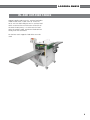
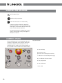
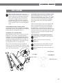
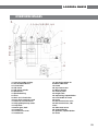
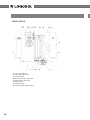
USER MANUAL
User manual in original format.
article no: 0458-395-2106
LOGOSOL DH410
Read through the user manual carefully and make sure you understand its contents
before you use the planer/moulder.
This user manual contains important safety instructions
Warning! Incorrect use can result in serious personal injury or even death to the
operator or others.
Thank you for choosing
a Logosol machine!
Welcome! We are very pleased that you have
demonstrated your confidence in us by purchasing
this planer/moulder and we will do our utmost to meet
your expectations.
Logosol has been manufacturing sawmills since 1988,
and since then we have supplied machines to satisfied
customers worldwide. We are want to assist you in
safely achieving the very best possible results from your
planer/molder. We therefore recommend that you take
the time to read this user manual from cover to cover
before you begin using the machine.
Remember that the planer/moulder itself is just part of
the value of the product. Much of the value is also to
be found in the expertise we pass on to you in the user
manuals. It would be a pity if that were not utilized.
We hope you get a lot of satisfaction from the use of
your planer/moulder.
Bengt-Olov Byström
Founder and Chairman of the Board,
Logosol AB
LOGOSOL is engaged in continuous development of its products.
We must therefore reserve the right to change
the design and form of our products.
Text: Bo Mårtensson
Document: Logosol PH360 Manual
Image: Bo Mårtensson, Lars Wahlström
Last Revised: February 2011
Manual, product no. 0458-395-2106
© 2010 LOGOSOL, Härnösand Sweden
2
LOGOSOL DH410
Table of contents
Safety instructions
4
Tools required
6
Machine description
6
Preparations
7
Setup
8
Chip management
8
In and outfeed table
9
Starting the sawmill
10
Control panel
10
Top cutter
11
Moulding knives in the top cutter
12
Side cutters
13
Instruction, spring plate
15
Instruction, fixed & variable feed
16
Maintenance
17
Planing/Moulding tips
18
Starter package DH410: moulding
knives & examples of combinations
19
Wiring diagram
22
Overview
23
Technical data
25
EC Declaration
27
3
Safety instructions
•
Use approved ear protection and protective
goggles. Hearing can be damaged after only a
short exposure. Use approved safety goggles.
Splinters and pieces of wood can be hurled our
with with great force when the machine is in
operation.
Do not feed into the machine work pieces that
are so conical that the feed roller risk losing hold.
Always measure the workpiece and set suitable
thickness and width before planing. There is a high
risk of accident if the feed roller looses its grip of the
workpiece.
•
Warning! Cutting tools. Never stick hands or
tools above or beneath the machine table or in
the chip outlets while the machine is running.
Small dimensions must be planed using fixtures,
e.g. a piece of wood with a customized groove
that extends along the full length of the table. The
same applies when the work piece is higher than it
is wide.
•
Before starting the machine:
- Get familiar with all functions and setting
possibilities before using the machine.
- Make sure that the cutter can rotate freely, and
that no tools or loose parts are left inside the
machine.
- Make sure that the cover is properly closed and
that the looking screw in the cover is securely
tightened.
- Make sure that all knobs, screws, nuts, fences,
knife gibs, cutter heads knives , protective covers,
in- and out-feed tables, etc. are firmly tightened/
secured.
•
Make sure that the chip hoses are fitted with hose
clamps, and that the chip extractor is switched on.
•
Make sure that no other person besides that
operator is within the safety distance
•
In this manual, the phrase ”disconnect the power”
means that the cable with the CEE plug, which
supplies the machine with electricity, is pulled out
and placed so that no unqualified person can
connect it to the machine.
•
Disconnect the power by pulling out the plug, and
wait for the cutter head to stop before :
- opening the cover to change planing/moulding
knives, or to carry out any other opertion above or
beneath the machine table .
- replacing belts or performing any other servicing or
cleaning.
- moving the machine.
- leaving the machine unsupervised.
•
Chip hose and chip extractor must be fitted securely
to the machine’s chip duct, e.g. with hose clamps.
For your own safety, read the entire instruction
manual carefully and do not start the planer/
moulder before you have understood everything.
Risk of cutting injuries. Use protective gloves
when handling the knives. It is especially
important that you wear gloves when loosening
or tightening the lock screws for the knives and
the fences (as there is a risk that you slip with the
spanner).
This symbol means ”WARNING!”. Be extra
vigilant when this symbol appears in the
manual text.
This symbol is followed by a prompt. Be
extra vigilant when this symbol appears in
the manual text.
•
4
This document is mainly a machine instruction. It
does not constitute training in machine planing.
If used incorrectly, the Logosol DH410 can cause
serious personal injury. Always be focused and
careful when using the machine.
•
Ensure that non-authorized persons do not use this
moulder.
•
Never stand along the the workpiece’s extension line
as kickback can occur, and bits of the workpiece can
be thrown out of the planer/moulder. Also knots,
splinters, or pices of the knives can be hurled out
with great force. Always stand at the side of the
in-feed table.
•
Only one work piece at a time may be fed through
the machine.
•
Make sure that the machine is set up so that the
feed roller (5*) take a firm hold of the work piece.
LOGOSOL DH410
•
•
The machine should be equipped with in- and outfeed tables of a length of at least 1 m (3.28 ft) each.
•
Do not wear loose-fitting clothing or anything else
that can get caught in the machine’s moving parts. If
you have long hair you should put it up in a reliable
way.
Lift the planer/moulder using a fork-lift or
pallet jack.
Applications
•
Always work in good lighting.
•
Do not use the machine under the influence of
alcohol or other drugs.
•
Keep the worksite tidy. Do not leave anything you
can trip over lying on the ground.
•
Never put your hands or any tools on the machine
table while the machine is running.
•
Do not climb up onto the machine.
•
Do not step on the machine’s power cable. The
cable should be secured to the ceiling.
•
Place the machine so that the emergency stop is
not blocked.
•
For maximum electrical safety, a residual current
device should be used.
•
The machine must not be modified or added to.
Only use original parts from Logosol. after servicing,
the machine must be restored to its original
condition.
•
The warning labels of the machine are there for
everyone’s safety. Damaged or illegible labels must
be replaced.
•
Dull knives increase the risk of accidents.
•
Risk of kickbacks.
•
Minimum length of the workpiece: 300 mm (11.8’’).
general
•
Check the planer/moulder as soon as you
receive it. Report any transport damage to the
transport company immediately.
This machine can be used for planing and
moulding wood.
Hard materials such as teak, MDF, etc. require hard
carbide tools, see the Logosol-Toolbox catalogue.
The planer/moulder is designed for indoor use,
with temporary outdoor use.
Environmental requirements
The temperature in the premises in which the
machine is stored should be above freezng, unless
special measures are taken: Trapezoidal thread
bars, machine table, knives, etc, must be rustprotected with oil (e.g. Super-Flo 9999-000-5115).
Ventilation in the premises must be mechanical,
and of a good standard.
The planer/moulder must be connected to a chip
extractor, which is approved according to CEstandards, see page 10.
Safety distance
Other than the operator, no-one should
be within 3 meters (10 ft) of the planer/
moulder’s sides or 8 meters (26 ft) from
the in and outfeed sides during operation.
Mark a limit that prevents anyone
accidentally wandering into the risk area.
Tips: An extended infeed table is practical to use,
and prevents anyone coming into the risk area.
3m
(10 ft)
Demarcation
DH410 with in and
outfeed table
8m (26 ft)
Risk
area
Max 8 m (26 ft)
The operator’s work area
The barrier behind
the infeed side
3m
(10 ft)
5
tools required
A list of the tools required to be able
to work with the planer/moulder:
Allen key 4 mm (supplied)
Allen key 5 mm
Allen key 6 mm
Open ended wrench 10 mm (supplied)
Ring wrench 10 mm
Ring wrench 13 mm
Open ended wrench 30 mm (supplied)
(for milling spindle)
Adjustable wrench size 8 or 10
(for milling spindle)
Sliding caliper
Measuring tape or ruler
Super-Flo for the table
Whetstone
Silbergleit
Spray kit
Tips! Make a tool board with the tools you
need, and position it next to the planer/moulder
so that you can see it easily. Look at the tool
board before you start the planer/moulder to
see if any tools are missing. They could have
been left in the planer/moulder!
machine description
The DH410 is a planer/moulder that can work two
sides of a workpiece in one operation. The machine
is contained ina stable and strong chassis. The
machine table is made of cast iron.
The workpiece is fed, lying on the machine table,
through the machine by three feed rollers of which
one is an out-feed roller. The rollers are driven by a
chain transmission with separate motor.The work
piece is controlled laterally with an adjustable fence
and a pressure roller.
The work is done using a top cutter, which is hung
at both ends in the chassis, and a side cutter. Both
cutters are driven by separate motors, via a belt
transmission.
6
The cutters and feed rollers are covered by a foldable
protective cover. The protective cover is supplied with
a safety switch. Another safety switch sits behind the
top edge of the protective cover on the infeed side.
A 100 mm (4’’) hose is connected to the top cutter
and side cutter for connection to a chip extractor.
table surface
The table is cast in the highest quality. The table
surface is specially processed for the highest precision
and the best anti-friction qualities. When the
machine is new, it requires a running-in period until
the table gets a slightly shinier surface to optimize
the anti-friction qualities. During this period, we
recommend that you use a lubricant or Super-Flo
spray (item no. 9999-000-5115 ) on the table.
LOGOSOL DH410
preparations
Certain parts are not assembled on delivery for
transport and packaging reasons.
1. Assemble the control panel in place with the
arm where the cabling goes (22).
2. Assemble the fences.
3. Connect the planer/moulder to the chip
extractor.
4. Before the planer/moulder is connected to the
electrical circuit, check that all cutters can rotate
freely, and that all parts are fixed.
7
setup
Check your DH410 as soon as you receive it. Any
transport damage must be reported to the transport
company immediately.
Most of the planer/moulder is protected against
rust and can be stored in cold premises, but it will
require extra maintenance in the form of lubrication
for all the parts not protected against rust. See the
Maintenance section.
•
Place the planer on a stable and flat ground.
Preferably screw the planer down using the
holes in the base, if the castor set is not used.
•
Ensure that there is enough space at the in and
outfeed sides for the longest boards you want
to machine, and that there is enough space for
maintenance and timber stocks.
•
Connect the chip hoses and fix using the
hose clamps on the planer/moulder and chip
extractor.
•
Hang the planer’s electrical cable in the ceiling
or protect it in another way. Never step on the
cable. The planer/moulder should be connected
via an residual current device.
•
Ensure that lighting is good. There should be
good general lighting. Also set up a strong lamp
directly over the machine. Ensure that there is
no risk of glare.
Space requirements
The machine needs a space of at least 2 m (6 1/2 ft)
width. The length required depends on the length
of the workpieces you want to plane. The minimum
length is 2 x the length of the workpiece plus 2
additional metres.
Be aware of the risk of being crushed between
the workpiece and the wall if you use the machine
in a too small space.
chip management
The DH410 must be connected to a chip extractor
with a capacity of at least 3,000 m3/h (10,000 cubic
feet/hr). Logosol has a range of pipes, sleeves and
hoses. Ask LOGOSOL’s advice to find a chip-handling
system that suits you.
Remember that you need an air vent in your chip
container (e.g. a fine net or filter if you carry out
chip collection indoors). Poor suction is often due to
poor airflow from the chip container. If you work in
heated premises, remember that the fan will quickly
cool the space if you do not lead the filtered air back
into the building.Consideration must be taken for
fire risk and dust emissions (discharge) in connection
with chip collection.
8
Position the chip extractor so that you can
easily reach the switch, or let an electrician
connect the chip extractor to the free button
on the control panel of the planer/moulder.
Chips that are left in the planer/moulder must
be vacuumed up after every work session.
Technical requirements chip extractor
•
The chip extractor must be approved according
to the CE-standard.
•
The airflow ”without external connection” must
be approx. 4000-5000 m3/hour (13,000-16,500
cubic feet/hour).
Fire risk and dust emission in connection with
chip management.
•
(The manufacturer’s standard indication of
airflow.)
Contact the local authorities for advice in
designing a chip collection system to conform
with rules in your area.
•
The sleeve diameters for the planer = 100 mm
(4”) x 2.
•
The pressure loss in the planer is 26 mm of
water column at 25 m/s (1 inch of water column
at 82 ft/s) .
LOGOSOL DH410
In- and out-feed tables
Logosol supplies ready-to-use in- and out-feed tables
made of steel sheet (1 table. item no. 7500-0100010). You can also build your own in- and out-feed
tables. To ensure that no knife marks will be left on
the ends of work pieces, it is vital that the in-feed
table, the machine table, and the out-feed table are
exactly level with each other.
For the best results Logosol’s feed tables are to be
used.
9
Starting the machine
Risk of serious injury.
Read the safety instructions.
Check that the cutters can rotate freely.
Connect the planer electrically. Watch the
rotational direction. If you are standing by the
feeder gear, the rotational direction of the top
cutter must be counter-clockwise.
The connecting plug is supplied with a phase
reverser, which makes it easy to change the
direction of rotation.
Control panel
The top red button (B) is the emergency stop and
switches off the power to all functions. When the
emergency stop has been activated, it must be
pulled out again in order for the planer/moulder to
be re-started. For the function of the other buttons,
A
B
C
see picture below.
A. Start and stop
B. Emergency stop
(pull it out for re-starting the machine)
D
D
E
D
F
C. Indicator for connected power supply
D, E, F Indicators for each motor
G. Start, top cuttere
D
G
D
H
i
H. Start, side cutter
I. Start, feed
10
LOGOSOL DH410
top cutter
mounting and Adjusting planing knives
Before you open the protective cover on the
planer, ensure that the power is switched off and
that the cutters are not rotating. Use protective
gloves, particularly when you need to loosen
screws that are tightly fastened, or when you
are tightening screws (see safety instructions).
Beware of the planer knives. It is extremely easy
to cut yourself on these, even with the slightest
touch.
Adjust the planing knives so that they are at the
same level and protrude 1 mm (.040”). This is done
using an aluminum setting block (item no. 7500000-1020), found in the component packaging
on the planer table when the planer/moulder is
delivered.
Loosen the chip breaker’s lock screws slightly, and
pass the setting block over the knife. Adjust the
knife up or down until the knife brushes against
the block when it is passed over the knife. (The
planing knife protrusion can also be adjusted using a
magnetic adjuster for the top cutter, item no. 7500001-0050. See the instructions enclosed with the
magnetic adjuster.)
Disassembling the planer knives
The planing knivea are disassembled by loosening the
chip breaker’s (A) lock screws (B) and then unscrewing
the planing knives with adjuster screws (C).
Grinding the planing knife
Always grind the knives in pairs, so they are the same
height, min. 15 mm (.600”), otherwise vibrations
could occur in the cutter. The grinding angle must be
38 degrees. You can order a grinder from Logosol for
sharpening moulding and planing knives (Tormek T7
Grinder Logosol Edition item no. 7010-000-1025, Jig
for planing knives item no. 7010-000-1005).
After adjusting or replacing planing knives:
Make sure there no tools are left inside the
machine.
Make sure that all screws are securely
tightened.
Make sure that the cutter heads can rotate
freely before closing the protective cover.
Always set the top cutter by moving it upwards to
reduce any slack in the threads. If the top cutter needs
to be lowered, lower it half a rotation too low and then
raise it into the correct position.
A
Do you remember the safety instructions on
pp.4-5?
Setting block
B
Knife gib
F
Planing knife
Lock screw
Adjusting screw
D
E
C
11
moulding knives in the top cutter
Before you open the protective cover on the
planer, ensure that the power is switched
off and that the cutters are not rotating. Use
protective gloves, particularly when you need
to loosen screws that are tightly fastened, or
when you are tightening screws (see safety
instructions). Beware of the planing and
moulding knives. It is extremely easy to cut
yourself on these, even with the slightest touch.
The top cutter head have four tooling slots. As
mentioned above, the planer is delivered with two
planing knives assembled in two of the tooling slots.
In the other two tooling slots, moulding knives of
different sizes and profiles can be assembled.
•
Assemble the knife gib and the moulding knife.
See illustration below.
•
Insert the gib and the moulding knife in the
wide end of the slot in the cutter head.
•
Warning! Unbalance in the cutter creates
vibrations that can damage the planer and
cause personal injury.
Push the knife and gib into the groove. Measure
the position using the millimetre scale on the
cutter, and fix by tightening the screw tightly on
the back of the gib.
•
Moulding knives must always be mounted in
pairs, so that the cutter remains balanced.
The lock screw must not be placed over the area
where the tooling slots are extended.
•
Measure the position of the knife laterally and
assemble an identical knife in exactly the same
position on the cutter’s opposite side.
Moulding knives can be mounted in the top cutter.
Moulding knives must always be mounted in pairs –
opposite each other. A certain sideways offset of the
knife, can however be accepted, as long as the cutter
remains balanced.
Warning! If moulding knives with large
protrusion are used, make sure that the cutter can
rotate freely.
12
assembly
LOGOSOL DH410
side cutter
D
A
6
8
7
C
B
F
E
Before you open the protective cover on the
planer, ensure that the power is switched
off and that the cutters are not rotating. Use
protective gloves, particularly when you need
to loosen screws that are tightly fastened, or
when you are tightening screws (see safety
instructions).
The side cutter is fixed to the planer table. The
spindle is 30 mm (1 2/10”) in diameter, which is
a standard measurement. Upon delivery, the side
cutter is equipped with with planing knives, which
you can easily replace with moulding knives. For
reasons of safety, the cutters work with conventional
milling (the workpiece is fed towards the moulder’s
cutting motion).
Disassembling the side cutter
Loosen the nut on the spindle with a 30 mm wrench
(supplied) and an adjustable wrench. Unscrew the
nut and remove the cutter (A) and any spacing rings
under the cutter.
Replacing knives
Loosen the lock screw (B) with a 4 mm Allen wrench
(C) (supplied) and remove the chip breaker (D). Then
remove the knife (E) from the pegs (F). Insert a new
knife and tighten the locking screw tightly.
Ensure that you turn the knives in the right
direction when you mount them in the cutter.
The cutting edge must be turned towards
the chip breaker. Also check that the cutter is
facing the right direction on the spindle. Both
of the planer/moulder’s cutters turn the same
way as with conventional milling
Check that the spring plate in front of the
side cutter is not at risk of being bent towards
the cutter by the workpiece’s unplaned edge.
Pay particular attention when machining
workpieces of different widths.
Height setting
The side cutter’s height is set by adding or removing
the spacers that are supplied in the component
package on delivery.
Spacer height:
Spacer 40 mm
Spacer 20 mm
Spacer 10 mm
Spacer 5 mm
Schim set (0,1 – 2,0 mm)
art.nr. 7502-001-0038
art.nr. 7502-001-0042
art.nr. 7502-001-0044
art.nr. 7502-001-0046
art.nr. 7502-001-0230
13
To remove the planing knives from the side cutter,
loosen the knives’ lock screws that are recessed into
the cutters. Use a 4 mm Allen Wrench (supplied).
Spacers must also be placed above the cutter
so that it is fixed on the spindle. Use some
of the spacers that are not used for height
setting. Place the thickest spacer so that it lies
highest and extends a couple of millimetres
over the lowest threads on the threaded bar.
Then, screw on the nut on the threaded bar
and tighten it firmly.
test run
Always run a test piece and make subsequent
adjustments. Run a straight piece through the planer
at the slowest feed speed. Then measure the profile,
its height and width, and subsequently adjust the
cutters and the setting for the moulding knives if
required.
Grinding
To recover the sharpness of the knives, you can
grind the flat side of the knives. Thus you retain the
same profile for the pair of knives. Always grind the
knives in pairs, so that they have the same weight,
otherwise vibrations could occur in the cutter. You
can order a grinder from Logosol for sharpening
planing and moulding knives (Tormek T7 Grinder
Logosol Edition item no. 7010-000-1025, Jig for
moulding knives item no. 7010-001-1012).
If the profile of the knife is damaged, this should be
re-ground by a professional knife sharpener. This is
a service that is normally available locally, otherwise
contact Logosol.
14
LOGOSOL DH410
instruction, spring plate
The side cutter spring plate is used when you require
additional lateral pressure or when the planing/
moulding causes splinters in the timber.
• The spring plate is clamped between the chip guide plate, which is in front of the side cutter, and the screw plate with two threaded holes.
• Set the spring plate so that it touches the board of the smallest width.
• Maximum springing of the plate is 6-8 mm.
• When machining boards that varies more than 6-8 mm in width, the spring plate should not be used.
• Run the workpiece twice through the planer/
moulder if it is of very large dimensions.
15
instruction, fixed and variable feed
fixed feed
AGIP
BLASIA 32
SHELL
A.T.F DEXRON
ESSO
A.T.F DEXRON
MOBIL
A.T.F 220
Assembly (if the variable feed motor
is not assembled in place)
CASTROL
DEXTRON II
Assemble the feed motor package on the last feed
roller. Make sure that the torque stay is in place.
Lock this with the central screw on the roller.
BP
AUTRAN DX
The fixed feed do not require maintnenance. (For
variable feed, see below.)
VARIAble feed
Warning! Do not turn the adjustment knob when
the planer/moulder is not running.
Setting the feed rate
Turn the wheel clockwise to increase the speed.
Indicator dial for the feed rate
The indicator dial is/must be mounted in the hub
of the wheel. It works like an indicator that has a
weight in one part, so the indicator moves. The
black indicator shows a figure.
The indicator dial has a relative scale. See the
numbers as an indicator. The higher the number, the
greater the speed.
Start the planer/moulder and turn the wheel so the
planer reaches minimum speed.
Remove the indicator dial and turn it so the indicator
is set to zero. Then press the indicator dial in with
the indicator pointing upwards towards zero.
Use the indicator dial so that you can return to the
best speed for the profile you are planing.
16
If you have a 2-12 m/min (6-39 ft/min) gear:
0 on the indicator dial is 2 m/min (6 ft/min)
8 on the indicator dial is 12 m/min (39 ft/min)
Maintenance
Fluid should be visible in the fluid level glass. The
level is checked when the variator is not
running.
Top up if no fluid is visible in the glass. Use oil for
automatic gearboxes according to the table below,
or use compatible oil.
The variator is filled with AGIP BLASIA 32 at the
factory and does not normally require an oil change
during its life.
The worm gear oil does not normally need changing
or topping up during the life of the gear.
LOGOSOL DH410
MAINTENANCE
The DH410 is easy to maintain as 95% of the
planer/moulder is protected against rust. The
maintenance required, is mentioned below. Ensure
that the power to the planer/moulder is switched off
before beginning maintenance.
After each work session:
• Clean chips from the planer/moulder. Also
remove any chips from under the planer/
moulder.
•
Clean any resin off the table. Use mineral spirit
if necessary. Lubricate the table with paraffin oil,
for example.
in good condition.
USING OR STORING IN COLD OR DAMP
ENVIRONMENTS
If the planer will be stored in a cold or damp
environment over a longer period, all corrosive parts
must be treated with a rust inhibitor (Super-Flo).
Cover the machine.
Water can condense in closed spaces. Check that
the motors are dry inside by loosening the draining
plugs. Check the control panel box. If necessary, drill
a 4 mm draining hole in the bottom of the control
panel box.
Maintain at regular intervals as
follows
Lubricate these areas regularly:
• The feed roller bearings.
• Trapezoidal bars and their top and bottom
bearings.
• The chain for setting table height.
• The chain driving the feed rollers.
• The cast iron table.
For lubrication:
Super Flo, dry lubricant, item no 9999-000-5115.
For cleaning plastic and rubber parts:
Silicone spray item no 9999-000-5110.
For rust protection:
Universal oil, item no 9999-000-5105.
For cast iron table:
Silbergleit, item no 7500-001-5067.
Check that all screws and bolt connections are tightened and that cables and electrical connectors are
17
planing/moulding tips
1. When you have finished moulding a profile that
you know you will be moulding again, feed in
a board of approx. 1 m (3 ft) long, then switch
off the planer/moulder when this has been
fed in. Lower the table and remove the board.
Next time you are going to mould this profile,
the board can be used as a template for both
cutters and fences. Also note on the test board
which shims and knives you used for it, as well
as the position of the moulding knives in the
horizontal cutter.
2. You can experiment with adjusting the pressure
on the feed rollers yourself. Note the basic
settings before you start, so you can always
return to them. The springs must normally
be tensioned more on the right-hand side,
particularly if small objects are machined. The
feed rollers must be balanced on the object, and
not press more on either side.
3. When a small amount of timber is to be
moulded, the setting becomes easier and
often quicker if you first plane one side of the
workpiece before you mount the moulding
knives, and then turn the board so that the
planed side faces the machine table while the
sides are being milled. This means that you only
have to set the height on the side cutter once
when making tongue and groove.
18
TB90-011
5.090:-
Starter package with knives and
gibs for the DH410
GET STARTED AT ONCE! 10 pairs of
moulding knives tha will be very
useful to you!
The starter package of moulding knives
enables you to produce a wide range of
profiles. Our experience tells us that these
profiles will without doubt be very useful
to you.
The package includes: 10 pairs of
moulding knives of HSS, and 2 pairs of
knife gibs.
You can do all thi s and mu ch
mo re wit h the sta rte r pac kag e!
Starter package with
knives for the two-sided
planer/moulder DH410
Incl uded in the
Rustic style casing
Plain casing 3
Plain casing 2
Plain casing 1
Incl uded in the
casing sta rter pac kag e!
Plain 3
Plain 2
Plain 1
Rustic style
Ma ke jois ts tha t
are up to 410 mm
Close rounded T&G
Open bevelled T&G
Plain T&G
Open rounded T&G
Incl uded in the
panelling sta rter pac kag e!
Rustic style
Rounded edge
Bevelled edge
Width: Up to 410 mm. Height: Up to 60 mm.
Incl uded in
Incl uded in
the sta rter
wainscot mouldings the sta rter joist and decking pac kag e!
pac kag e!
Produce joists and decking of different dimensions.
Rustic style cornice
Plain cornice
Skirting boards sta rter pac kag e! cornices sta rter pac kag e!
Incl uded in the
Examples of wood profiles you can make with the knives in the starter package
Produce all wood products you need with the DH410
LOGOSOL DH410 Two-sided planer/moulder
LOGOSOL DH410
19
basic package Dh410 item no: tb90-011
10 pairs of moulding knives of HSS + 2 pairs of knife gibs
for making:
Casing
Cornice
Rounded panelling Skirting board
Bevelled panelling Joists & Decking
Wainscot moulding
20
KNIFE GIB -038 X2
Double rounded T&G
(open)
Double rounded T&G
Double bevelled T&G
(open)
Double bevelled T&G
Joists & decking
T&G
Plain skirting
board 2
Plain casing 2
Plain skirting
board 1
Plain casing 1
Rustic style
skirting board
Rustic style casing
Rounded skirting
board
Rounded casing
Knife mounting in the LOGOSOL DH410
Bevelled
wainscot moulding
Rounded
wainscot moulding
Wainscot moulding, sawn neck
Plain cornice
Swan neck
cornice
LOGOSOL DH410
21
wiring diagram
wiring diagram
Lethal voltage. Incorrect
connection is potentially fatal.
Note that you need authorization
to open or intervene in the electrical equipment.
Ensure that the power supply is
switched off before you open the
system.
WIRING DIAGRAM, PLANER/MOULDER DH410
Earth
ELECTRIC BOX
FUSE
CONTROL PANEL
WHITE LAMP
VOLTAGE ON
FUSE
WHITE LAMP ON
MAIN SWITCH
ON
TOP CUTTER MOTOR
CONT.
OVER
HEATING
PROTECTION
CONT.
CONT.
YELLOW/GREEN
WHITE LAMP
ON
ON
SIDE CUTTER MOTOR
CONT.
OVER
HEATING
PROTECTION
CONT.
CONT.
YELLOW/GREEN
ON
FEED MOTOR
CONT.
OVER
HEATING
PROTECTION
CONT.
CONT.
YELLOW/GREEN
OFF
22
LOGOSOL DH410
overview images
1/ Crank for height settings
2/ Anti-kick-back device
3/ in-feed roller
4/ Side cutter
5/ Side cutter spindle
6/ Spindle nut
7/ Spindle bearing
8/ Cover
9/ Chain for in-feed roller
10/ Four chain sprockets, feed
11/ Chain for out-feed roller
12/ Chip guide plate top cutter
13/ Top cutter
14/ Worm gear, feed
15/ Torque bar
16/ Transmission cover
17/ Feed motor
18/ Tensioning wheel for
machine table chain
19/ Frame
20/ Top cutter motor
21/ Motor bracket
22/ Control panel
23/ Height scale
24/ Top bearing, trapezoidal bar
25/ Lock handle for fence
26/ Fence
27/ Belt transmission cover
28/ Belt transmission, side
cutter
29/ Side cutter motor
30/ Trapezoidal bar
31/ Sprocket, trapezoidal bar
32/ Chain
23
from above
33/ Front spring plate
34/ Chip duct, side cutter
35/ Pressure roller
36/ Belt transmission, top cutter
37/ Belt transmission cover
38/ Electric box
39/ Machine table
40/ Out feed roller (rubber roller)
24
LOGOSOL DH410
Technical data
DH410
Length and width
1000 x 840 mm
Height
1230 mm
Weight
225 kg
2-sided planing/moulding
Width
325 mm (12 7/8’’)
Height
Max 100 mm (3 15/16’’)
PLANing (assembly required)
Width
410 mm (16”)
Height
260 mm (10”)
Top cutter
Diameter
72 mm (2 8/10”)
Width
410 mm (16”)
Output
3 kW
Rotational speed
6000 rpm
Take-off when planing
0-8 mm (0-3/10”)
Take-off when moulding
Max. 10 mm (4/10”)
side cutter
Diameter of spindle axel
30 mm (1 2/10”)
Cutter height
Max. 100 mm (3 15/16’’)
Diameter
Max. 140 mm (5 5/10”)
Output
3 kW (Hk)
Rotational speed
6000 rpm
Cutting depth
Max. 30 mm (1 2/10”)
SUPPLIED SIDECUTTER
Type
TB90
Diameter, body
90 mm (3 5/10”)
Height, body
40 mm (1 6/10”)
Cut, type and width
Planing knife, HSS, 50 mm (2”)
FEED, PLANET VARIATOR
Output
0.18 kW (1 hp)
Feed rate
6m/min (19 1/2 ft/min), or optional 2-12 m/min (6-39 ft/min)
ELECTRIC SYSTEM
Total output
6.2 kW (22 hp). All motors are equipped with overheating protection.
Electrical connection
3-phase, 400 V, 16 A, 16A fuses are sufficient for less demanding production.
25
26
LOGOSOL DH410
Declaration of conformity
The Machinery Directive 2006/42/EG
Annex 2, section A
AFS 1994:48, Annex 2, section A
Manufacturer
MOReTENs AB, M10
Lugnviksvägen 147
SE-831 52 ÖSTERSUND
SWEDEN
hereby guarantees that the MOReTENs DH410
Planer/moulder, Nr 360-000 fulfills the requirements
in AFS 1994:48 and 98/37/EG, the EMC directive
2004/108/EG, standard EN61000-6-4 and LVD directive 2006/95/EG
Östersund 2010
Bo Mårtensson, CEO
27
Logosol Sweden
Fiskaregatan 2, S-871 33 Härnösand, SWEDEN
Phone +46 (0)611-18285 | Fax +46 (0)611-182 89
[email protected] | www.logosol.se