1
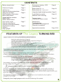
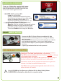
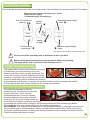
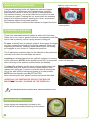
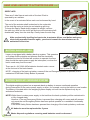
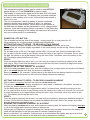
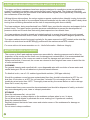
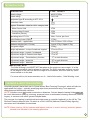
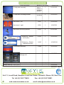
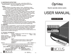
The LEGACY turning bed Product Code: CB3SP-200-110 User Manual September 2013 edition NE XUS DMS Ltd R BEFORE USING THE BED IT IS IMPORTANT THAT ALL STAFF INVOLVED IN THE OPERATION OF THIS BED HAVE CAREFULLY READ AND FULLY UNDERSTOOD THE OPERATING INSTRUCTIONS CONTAINED IN THIS USER MANUAL. This manual should be retained and be readily available for future reference Some key points... This User Manual contains important information and guidance covering the safe and reliable operation of the Legacy Turning Bed. Only those members of staff who are trained in the use of this bed and have full knowledge of a patients condition/ medical history should be authorised to operate the bed. They should fully understand and be proficient in: Operation of each electrically operated function of the bed. How to deal with emergency situations such as CPR lowering, levelling the bed manually and how to deal with malfunctions. If a visiting child is present then there must be strict supervision by an adult, paying particular attention to the ‘risk zones’ of the bed eg: underneath - where there is a risk of entrapment, or close to foot or hand-operated controls - where there is a risk of accidental operation of a bed function. In this situation, or where a patient is to be left unattended in the bed, then you should ensure that the BLACK Safety Button is pressed to avoid operation of any bed function by unauthorised staff (Page 5) To prevent potential damage to the roving hand control and to avoid accidental operation of a bed function, it should be secured to the bed frame when not in use. (Page 6) Pay particular attention to the foot-operated controls as unintentional operation is more likely than with the hand-operated controls. For example, an object may fall on to a foot pedal or it may be activated by another piece of equipment coming into contact with it. 2 CONTENTS Before using the bed Page 2 Emergency lowering - CPR Hand levelling Page 9 Features of Legacy Initial set-up General operating instructions Safety key operation Red Emergency Stop button Black Safety Button Central braking operation Hand control Rocker switch control Foot control control Fitting the handling bar Fitting the footboard assembly Single button levelling Siderails Angle gauges Page 3 Page 4 Battery back-up - bed Battery back-up - weighing system Page 10 Page 5 Page 6 Page 7 Page 8 Integrated digital weighing system Page 11 2-part Mattress system Mattress care & cleaning Page 12 Technical data Cleaning & infection control Page 13 Maintenance Troubleshooting Operational risk management Disposal of equipment Page 14 Approved accessories Page 15/16 FEATURES OF The Legacy TURNING BED Legacy features the following electrically-operated functions: Backrest angle adjustment (Page 6) Leg-lift, knee-break & Fowler position adjustment (Page 6) Bed height adjustment (Pages 6 & 7) Lateral tilt adjustment - left & right (Pages 6 & 7) Elevating side-flaps at each side (Page 6) Trendelenburg/anti-Trendelenburg (longitudinal tilt) (Pages 6 & 7) Single button self-levelling to horizontal from any position (Page 8) The actuators which operate these functions are driven by electro-mechanical linear motors with maintenance-free permanent lubrication. The bed utilises analogue control technology which activates actuators with no delay once a finger or foot control is pressed. On releasing a control button then movement stops immediately. The functions are operated using the following controls: Roving Hand Control (securely mounted on the bed frame) (Page 6) Foot-operated Controls - at each side/end of the bed (Page 7) Finger-operated Rocker Switches (Pages 6 & 8) The actuators and controls are galvanically isolated from the mains 240 voltage and operate at a low voltage (24v DC). ! Do not exceed an operating time of maximum 6 minutes per hour The bed is equipped with a battery backup system which operates on a power-buffer principle. If the mains power fails then all electrically-operated functions will continue to operate for some time. This system also allows all functions to be operated for patient care when the bed is away from the ward eg. for CT scan. The integrated weighing system, with digital read-out, can record a patients actual weight or changes to their weight. Strategically placed angle gauges enable accurate positioning of the patient. 3 INITIAL SET-UP OF LEGACY Only authorised staff should be permitted to install and set up the bed ready for use. Electrical fuses at the installation site must not exceed 16 amps and voltage & frequency should match those indicated on the CE label attached to the bed. Select the location of the bed carefully, ensuring that the floor is flat and even. Loose floor coverings should be avoided as they can be damaged when moving the bed to a new location and they make it more difficult to manoeuvre the bed safely. Ensure that the mains electrical power cable from the bed is securely plugged in to the electrical safety connector and that the 3-pin plug is then secured in the mains power wall socket outlet. Running the mains power cable along the floor is recommended, but it should be kept clear of the bed castors. Pay particular attention to this when manoeuvring the bed, as running the castors/bed over the mains power lead can result in damage to the power lead. NEVER run the power cable through the mechanical components of the bed as there could be a risk of crushing. The mains power cable can exit the bed from a choice of 2 locations - these are carefully sited locations to ensure the power lead is kept away from the moving parts of the bed. 1. At the foot end of the bed, where the normal cable strain-relief is located. 2. At the head end of the bed, where the cable’s attachment point may be clipped into the snap-in lock. Once power to the bed has been established then the integrated battery chargers will continuously charge the back-up batteries. Should the mains power supply be interrupted then the back-up batteries will operate all bed functions for a limited time (10 cycles). ! Rolling the bed over the mains power cable may damage the cable and/or connections with the potential to cause electrical shock. GENERAL OPERATING INSTRUCTIONS Before a patient occupies the bed the following checks should be made: Ensure all electrical connections are secure. Ensure all electrically operated functions are working correctly. If not, then seek technical advice. Ensure that there are no obstacles within the area of movement of the bed eg. Chairs, tables etc. Once a patient is lying in the bed ensure that limbs are within the area of the mattress support and not resting on the bed subframe to avoid entrapment. If the bed is operating on battery back-up, time-consuming or unnecessary adjustments should be avoided in order to maximise battery power during a mains power failure. If the thermal fuse has been triggered, after a period of operation in excess of 6mins/hour, then it will be necessary to allow the fuse to cool before attempting further adjustments of the bed. ! 4 Never run the mains power cable of any ancillary device through the moving mechanical parts of the bed due to the risk of crushing. SAFETY KEY OPERATION There are 2 Safety Keys supplied with Legacy. No electrical function will operate until one of them is inserted into its cradle at the foot end of the bed - bottom right hand side. 1. MASTER (Full Function) KEY Long key with red dots. This key unlocks ALL electrical functions. 2 red dots by the finger pull are visible when the key is inserted into its cradle - it is therefore immediately apparent that it is the full-function Master Key which is inserted. 2. DEFAULT (Restricted Function) KEY Short key - this key unlocks all electrical functions EXCEPT backlift and leglift adjustment which, potentially, could be hazardous to the patient. These are disabled when using the Short key. BLACK SAFETY BUTTON Pressing the BLACK Safety Button immobilises ALL bed functions, whilst maintaining power to re-charge the battery back-up system. Press this button if the bed is to be left unattended, in order to avoid accidental operation of one or more bed functions. Press the button again to provide power to operate ALL bed functions. A green light indicates that the bed is powered. RED EMERGENCY STOP BUTTON Press the RED Emergency Stop button in the event of extreme malfunction of the bed, either electrical or mechanical. The RED button immobilises ALL bed functions, including re-charge of the battery back-up system. Note that the 240v AC supply is still present at its point of entry to the bed until the 3-pin plug is removed from its wall socket. This button should also be pressed if the bed is to be placed in storage or is being transported between sites. The RED button must be pulled upwards, when safe to do so, before the bed will function. ! Use of EITHER the Red Emergency Button OR the Black Safety Button OVERRIDES the Safety Key operation for complete safety. 5 CENTRAL BRAKE OPERATION CENTRAL BRAKE CENTRAL BRAKE OPERATION Once the bed is positioned in its chosen location then the centrally operated brakes must be applied. The foot-operated brake lever has 3 positions and is colour-coded: Position 1 - RED side depressed - all 4 castors are LOCKED Position 2 - CENTRE position - all 4 castors are RELEASED Position 3 - GREEN side depressed - 1 castor at the head end is locked parallel to the bed 1 castor at the head end is free to rotate 2 castors at the foot end are free to rotate Position 3 is an aid to steering the bed when moving to a new location Position 1 - fully locked Position 2 - fully released HAND CONTROL UNIT The roving hand control unit controls adjustment of mattress support height; lateral tilt & Trendelenburg/anti Trendelenburg. When not in use the hand control must be securely located on its mounting bracket below the mattress platform. Lateral Tilt Tilt right * Tilt left * Position 3 - for steering ROCKER SWITCH - FINGER CONTROL Individual rocker switches, located at each side and at the foot end of the bed, control the adjustment of the side flaps at each side of the bed, also the backrest & legrest. The side flaps can be adjusted individually or in pairs. up down ROCKER SWITCH - SIDE FLAPS Bed height Bed raise Bed lower Head down Head up Trendelenburg * from patient’s view when supine Hand Control stored when not in use. Electrical adjustment of a single side flap. Electrical adjustment of both side flaps together. ROCKER SWITCH - BACK / LEG LIFT At each side of the bed are 2 RED rocker switches controlling the adjustment of back-lift, leg-lift and Fowler position. Electrical adjustment of legrest / knee-break/Fowler angle. Electrical adjustment of back-rest angle. IMPORTANT NOTE: Built-in limit switches override the use of the backrest and backrest side flaps in some positions to prevent collision damage to the side flaps when elevated. When the backrest side 0 . flaps are fully elevated the backrest will not raise above 17 . When raised backrest is needed at the Same time as side flap full elevation then the backrest must be raised FIRST to not more than 170 6 BEFORE attempting to elevate the side flaps. The backrest can only be fully raised above 170 if the 0 backrest side flaps are not elevated above 8 . FOOT PEDAL CONTROL The foot pedals located at each side and at both ends of the bed allow foot-operated control of 3 functions: Mattress support height adjustment (up / down) Lateral tilt (left / right) * Trendelenburg/anti-Trendelenburg Anti-Trendelenburg - head up Lateral tilt left* Mattress support height - raise Lateral * tilt right Trendelenburg - head down Mattress support height - lower Left / right turn from patients view when lying in bed * ! Do not exceed an operating time of maximum 6 mins. per hour ! Before using lateral turn functions ensure patient safety by elevating side flaps on the side of the bed in the direction of turn FITTING THE HANDLING BAR The Handling Bar is fitted at the foot end of the bed by positioning over the mounting ‘horns’ and lowering into place. Once correctly positioned, the 2 lever arm clamps should be tightened by turning clockwise. Once tight, the lever arm clamp handles Mounting ‘horns’ Lever arm clamps can be re-positioned (without loosening the clamps) by pressing the central button, turning to the required position and then releasing the button. To unscrew the lever arm clamps simply turn the clamp anti-clockwise. FITTING THE FOOTBOARD ASSEMBLY The footboard assembly is fitted by Footboard positioning over the mounting ‘horns’ and lowering into place. Once correctly positioned then the 2 lever arm clamps should be tightened by turning clockwise. Once tight, the lever arm clamp handle can Lever arm clamps Release latch be re-positioned (without loosening the clamp) Mounting ‘horns’ by pressing the central button, turning to the required position and then releasing the button. To unscrew the lever arm clamps simply turn the clamp anti-clockwise. ADJUSTMENT: The position of the footboard can be extended inwards or outwards from the bed to accommodate taller or shorter patients. Simply pull and hold the release latch, whilst at the same moving the footboard towards, or away from, the bed until the required position has been achieved. Push the release latch back into place. 7 SINGLE BUTTON LEVELLING A single self-levelling button will flatten the mattress support from any angle of lateral turn and Trendelenburg, leaving it horizontal at a choice of either its highest or lowest position. Two identical buttons, one at the head and one at the foot end of the bed are used. Pressing the ‘up’ arrow levels the mattress support at its highest position, pressing the ‘down’ arrow levels the mattress support at its lowest position. These buttons have no effect on the backrest or legrest functions. Mattress support horizontal - highest position Mattress support horizontal - lowest position EXTENDABLE SIDERAILS There is an extendable siderail located at each side of the bed. When not in use, each is ‘parked’ below its corresponding side-flap and is held in place by a silver, spring-loaded, locking pin. To raise a siderail from its ‘parked’ position, first support its weight and then release the locking pin by pulling sideways. Whilst still supporting the siderail, carefully rotate upwards until the locking pin engages in your choice of 3 adjustment positions. Locking pin The 3 adjustment positions allow for the siderails to be positioned vertically even when the side-flaps are raised. Lowering the siderails back into the ‘parked’ position is a reverse Releasing the siderail for stowing of this procedure. NOTE that the siderails must NOT be extended under the side-flap when returning to the ‘parked’ position below the sideflap. To extend the siderails, pull the silver, spring-loaded locking pin downwards and hold, slide the siderail a short distance then release the locking pin. Continue to pull the siderail towards the foot of the bed until the locking-pin locates in its new position. NOTE that the siderails must be RETRACTED before lowering into their ‘parked’ position below the side-flaps. Locking pin 1 UNDER NO CIRCUMSTANCES SHOULD THE BED BE MOVED BY PULLING / PUSHING ON THE SIDERAILS. Extending the ‘trombone’ siderail ! Use Risk Assessment to decide when siderails should be used. ANGLE GAUGES Angle gauges are strategically located on the bed to allow for accurate positioning of the patient. 8 EMERGENCY LOWERING - CPR In the event of an emergency, both the back-rest and leg-rest can be simultaneously and instantaneously lowered by the use of one of two release levers. There is one lever on either side of the bed, below the mattress support, towards the foot end. Before activating CPR emergency lowering, please bear in mind: - Nursing staff should stand well clear of the moving parts of the bed. - Once started, emergency lowering must be continuous, with the lever held in until the back-rest Single lever lowering and leg-rest have been fully lowered. Failure to do so may damage the Gas-pressure spring damping release mechanism. - Although the lowering action of the backrest is ‘dampened’ by a gas spring unit to minimise the speed of descent, the weight of the moving bed parts together with that of the patient being lowered may cause some patient trauma - the extent of this risk should be assessed prior to use of CPR lowering. HAND LEVELLING DUE TO ACTUATOR FAILURE LATERAL TILT In the event of actuator failure the mattress support can be levelled from any angle of lateral tilt to the horizontal position by means of a mechanical hand wheel - even with a patient in the bed. Only one person is needed for this activity. First identify the toggle lever needed to release the hand wheel this is situated centrally under the mattress support on the left of the bed. Remove the security lock-pull and move the lever through 1800 (this prevents the mattress support being operated by the actuator). Remove the security lock-pull from the hand wheel, pull out the spring-loaded handle and continually turn the hand wheel clock Mechanical or anti-clockwise, according to which way the mattress support is hand wheel turned, until the mattress support is horizontal. Toggle lever Security lock-pull After use, the hand wheel must be turned continually in the opposite direction until the release pin on the toggle lever will easily locate back into its hole. This will then allow the mattress support to be operated by the lateral tilt actuator again following repair. Replace all security lock-pulls. Spring-loaded locking pin LONGITUDINAL TILT (TRENDELENBURG) A similar system to the above levels the mattress support from any angle of Trendelenburg to the horizontal position by means of a mechanical hand wheel. First identify the spring-loaded locking pin needed to release the hand wheel - this is situated centrally behind the foot controls on the left of the bed. Remove the security lock-pull from the hand wheel and pull out the spring-loaded handle. Then pull and hold out the spring-loaded locking pin (this prevents the mattress support being operated by the actuator) before turning the hand wheel clock or anti-clockwise (according to which way the mattress Mechanical Security lock-pull hand wheel support is turned) until the mattress support is horizontal. After use, the hand wheel must be turned in the opposite direction until the locking pin clicks freely back into its hole. This will then allow the mattress support to be operated by the Trendelenburg actuator again following repair. Replace all security lock-pulls. ! After mechanically levelling bed parts due to actuator failure, and before using any electrically-operated function again, you should consult the manufacturer or an authorised technician. 9 HAND LEVELLING DUE TO ACTUATOR FAILURE CONTD SIDE-FLAPS There are 2 side flaps at each side of the bed. Each is operated by an actuator. In the event of an actuator failure each can be lowered by hand. The end of the actuator shaft is attached to the underside of the side flap using a clevis pin and retaining split ring. To lower the flap by hand simply support its weight, remove the split ring, slide out the clevis pin and move the actuator shaft downwards, away from the side flap. Gently lower the side flap. Clevis pin & split ring After mechanically levelling bed parts due to actuator failure, and before using any electrically-operated function again, you should consult the manufacturer or an authorised technician. ! BATTERY BACK-UP - BED Legacy is equipped with a battery back-up system. This operates on a power buffer principle and ensures that the electrically operated functions of the bed will continue to operate for some time should the mains power supply be interrupted, or when the bed is used away from the ward. There are 4 x 6V/12A/h NiCa batteries located under a cover at the foot end of the bed chassis. Back-up batteries NOTE - charging of the back-up battery ceases if the red Emergency Button is pressed, but is maintained if the black Safety Button is pressed. BATTERY BACK-UP - WEIGHING SYSTEM The digital weighing system has a separate back-up battery to ensure continued operation during interruption to the mains power supply or when, for example, moving the bed to a new location. The battery is located within the weighing system display unit and can be replaced only by an authorised technician NOTE Whilst there is mains power supply to the bed then the back-up battery will be maintained in a fully charged state. However, if the red Emergency Button is pressed then charging will cease and will resume only once the red Emergency Button has been pulled upwards to re-establish functionality of the bed. If the black Safety Button has been pressed then charging of the back-up battery continues. 10 ! All batteries must be replaced after 2 years ! Waste disposal regulations covering used batteries must be observed INTEGRATED DIGITAL WEIGHING SYSTEM Toggle switch - reset to zero The integrated weighing system can be used to read ACTUAL patient weight or to read CHANGES in patient weight. The display is located at the head end of the bed, at the left hand side and below the side-flap. The display can be pulled outwards in order to take readings or to re-set. It should be pushed back in when not in use. The unit incorporates a back-up battery to ensure continued operation during mains power failure or when, for example, moving a bed to a new location. Whilst there is mains power to the bed then this battery will be maintained in a fully charged state. However, if the red Emergency Button is pressed, or the Safety Key is removed then charging of the battery will cease and will resume only once mains power is re-established. Power On / Off button POWER ON / OFF BUTTON This is located on the top face of the display - simply press for ‘on’ and press for ‘off’. When switched on, a check routine is performed automatically. SETTING THE SCALE TO ZERO - TO RECORD ACTUAL WEIGHT Before a patient occupies the bed for the first time the scale should be set to zero. This process will ‘zero’ the display regardless of the items already on the bed eg. Sheets, blanket, pillows etc. On the back edge of the unit is a toggle switch which, for normal use, should be switched to the left. In order to set the scale to zero simply move the switch to the right for 3 seconds. Do not touch the bed, the switch or the digital display during this time. After 3 seconds, return the switch to the left. The display should now be set to zero. VERIFY Once the display has been set to zero, you can verify the system by placing a weight on the bed from 1kg to 10kg. Check that the display has recorded this and then remove the weight and check that the display has returned to zero. READING THE ACTUAL WEIGHT OF A PATIENT After the display has been set to zero, and with a patient now occupying bed, the system will display his or her actual weight each time the system is switched on. Bear in mind that if, for example, 2 pillows were on the bed when the display was set to zero then those 2 pillows should remain on the bed when taking subsequent readings. SETTING THE SCALE TO ZERO - TO RECORD CHANGES IN WEIGHT With a patient occupying the bed, the scale should be set to zero. This process will ‘zero’ the display regardless of other items, in addition to the patient, already on the bed eg. Sheets, blanket, pillows etc. On the back edge of the unit is a toggle switch which, for normal use, should be switched to the left. In order to set the scale to zero simply move the switch to the right for 3 seconds. Do not touch the bed, the switch or the digital display during this time. After 3 seconds, return the switch to the left. The display should now be set to zero. VERIFY Once the display has been set to zero, you can verify the system by placing an additional weight on the bed. Check that the display has recorded this addition and then remove the weight and check that the display has returned to zero. READING THE CHANGES IN WEIGHT OF A PATIENT After the display has been set to zero, with a patient occupying bed, the system will display changes to his or her weight each time the system is switched on. Weight gain will display as a positive reading but if weight loss has taken place then the display will show a solid black bar to the left hand side to indicate a negative figure. Bear in mind that if, for example, 2 pillows were on the bed when the display was set to zero then 11 those 2 pillows should remain on the bed when taking subsequent readings. 2-PART PRESSURE REDISTRIBUTION MATTRESS SYSTEM The upper and lower mattresses have been purpose designed to constitute a pressure redistribution system for patients in complex care nursing on the Legacy turning bed. The system profiles both laterally, coinciding with the movements of the backrest and legrest, and longitudinally, coinciding with the movements of the side flaps. Utilising thinner side sections, the unique system supports a patient when laterally turning, but avoids the risk of forcing the bulk of a conventional thickness mattress into the side of the patient’s body when turning thus minimising discomfort and the risk of compromising skin tissue viability. The lower mattress, being manufactured from CMHR foam, provides the structure and support for the patient’s body. The upper section provides pressure redistribution to prevent the development of pressure ulcers and is made from fast-acting heat-responsive visco-elastic foam. The lower mattress should be turned and rotated regularly to ensure that loading is evenly spread across both sides and both ends in order to minimise foam core fatigue and to lengthen product life. The upper mattress should be turned regularly for the same reasons but NOT rotated as the side flap slits are not central and would be wrongly positioned if the mattress were to be rotated. For more advice visit www.nexusdms.co.uk - Useful Information - Mattress Integrity MATTRESS CARE & CLEANING The covers on this 2-part mattress system are removable for cleaning purposes and to allow for inspection of the covers and the foam core for damage and contamination. It is recommended that frequent inspections of the covers are made to check for damage such as holes or cuts. Always ensure that, if removed, the covers are returned to their original foam cores to avoid the risk of cross-contamination. CLEANING For general cleaning and superficial dirt, use a disposable wipe with a solution of warm water and neutral detergent. Do not use abrasive or phenolic-based cleaners. To disinfect in-situ, use a 0.1% sodium hypochloride solution (1000 ppm chlorine). Should the mattress covers become contaminated then they should be laundered at 650C for not 0 less than 10 minutes, or at 95 C for not less than 3 minutes. Do not mangle or iron. Spin and tumble-dry at not more than 1300C. Thoroughly rinse and dry the covers before re-use or storage. Store flat in a cool, dry area. Contaminated foam cores cannot be decontaminated and should be disposed of safely, as should any cover damaged by cuts, tears or ‘sharps’ penetration. STORAGE Store the mattresses flat - do not fold. Do not place heavy or sharp objects on the mattress surfaces when in use / in store. Do not allow sharp objects to penetrate the cover coating (incl. Hypodermic needles). Keep the mattresses clean. Regularly inspect the interior foam cores and exterior covers of the mattresses for damage or contamination. Do not store in damp conditions. 12 TECHNICAL DATA DESCRIPTION Rated voltage Power rating TYPE: LEGACY 230 V/50Hz 1450 VA Equipment type B according to IEC 601-1 Protection class Ingress Protection class for drive components Main Control Unit Roving Hand Control Actuators (Drives) IP54 IP54 IP54 Operating time OT 10% Max. 6 mins. per hour Safe Working Load (SWL) Mattress sizes - upper/lower 175kg 200 x 105cm / 200 x 52cm Mattress weights (incl. Covers) Lower 3.7kg / Upper 6.7kg Bed gross weight 236kg Height adjustment - to top of mattress support 57cm to 97cm Adjustment angle - legrest / kneebreak Adjustment angle of mattress side flaps 0 to 50 00 to 900 Adjustment angle - Trendelenburg function 170 in each direction Adjustment angle - lateral tilt 300 in each direction 0 0 00 to 600 Adjustment angle - backrest IMPORTANT NOTE The Safe Working Load MUST NOT be taken as the maximum user weight - it is the maximum load which can be placed on the bed. The SWL must take account not only of the weight of the user but also the weight of the mattress, bed linen and any other items loaded on to the bed. For more advice visit www.nexusdms.co.uk - Useful Information - Safe Working Load CLEANING & INFECTION CONTROL Hospitals generally have their own in-house written ‘Bed Cleaning Procedure’ which will also be appropriate for Legacy - typically specifying wipe-clean procedures using Trust approved detergents and disinfectant solutions. NOTE: Solutions must not contain ammonia or abrasives. Solvent-based cleaning fluids must not be used. Mechanical cleaning, scouring, pressure hoses or automated cleaning cannot be used for Legacy, in common with other general hospital beds. The process for cleaning hospital beds and mattresses is controlled nationally in the UK by ‘The Revised Cleaning Manual/June ‘09 which is a DoH & NPSA (National Patient Safety Agency) document and is available for download. NOTE: When cleaning, lift the backrest and legrest sections to ensure that any protective panels beneath are included in the cleaning procedure. 13 MAINTENANCE All hinge points of the moving parts of the bed and the bearings on adjustment devices are fitted with maintenance-free bearings and must not be oiled or lubricated. After 6 months in use, thorough visual inspection and function checks are necessary in accordance with DIN EN 62353. Visual inspection must take account of the following: * Tightness of all threaded connections * Free movement of all mechanical hinge points * Check of the mains 240v power cable for pinching or other damage * Check of the mains 240v power cable for damage at the strain relief exit point Function checks - with no patient in the bed and no mattress, the following require special attention: * Correct operation of all electrically-operated moving parts * Completely extend and retract all actuators until automatic shut-off (audible click) * Verify that limit switches override backrest movement to prevent side flap collision damage * Correct operation of central braking functions TROUBLESHOOTING ! PROBLEM No powered functions will operate, regardless of which button is pressed. ACTION TO BE TAKEN Check electrical power supply & safety connector fuse. Check red Emergency Stop button & black Safety Button - switch on if necessary. Check safety key - if necessary insert key Lateral side flaps will not elevate Angle of backrest exceeds 17 - lower backrest Backrest will not raise regardless of which button is pressed Angle of lateral side flaps exceeds 8 - lower side flaps One of the powered functions will not operate regardless of which button is pressed Refer to ‘Service & Troubleshooting’ documentation 0 0 Problems encountered with bed powered functions, which cannot be resolved using the above guide, should be referred to the manufacturer or other suitably qualified technician OPERATIONAL RISK MANAGEMENT National regulatory directives in the country where Legacy is being used may require mandatory control procedures and documentation for: * Service maintenance * Adverse incidents / near incidents Effective Risk Management in the operational use of Legacy and its installation site are essential in order to minimise risk to patients and nursing staff; this can only be successfully achieved through continual hazard assessment and implementation of appropriate preventative measures in response. RESPONSIBLE DISPOSAL OF EQUIPMENT Disposal of the device and accessories should conform to National Standards and environmentallyfriendly measures current in the country of use. 14 LEGACY APPROVED ACCESSORIES Product description Weight kg No. per bed Traction support with guide pulley 0.628 3 LG.85.001 Traction support lower guide pulley 0.248 1 LG.85.002 Traction mounting bracket - long 0.716 1 LG.85.004 Head position support with face pad 0.756 2 LG.85.005 Head position support holder 0.449 2 LG.85.008 Accessory mounting bracket - short - left 0.505 1 LG.85.009 Accessory mounting bracket - short - right 0.505 1 LG.85.010 Accessory mounting bracket - long - left 0.630 1 LG.85.011 Accessory mounting bracket - long - right 0.630 1 LG.85.012 Accessory bar - head end 2.175 1 LG.85.013 1.255 1 LG.85.014 Left Left Right Right Product code Note: Accessory bar at the foot end of the bed is fixed. Handling bar Continued on Page 16 15 LEGACY APPROVED ACCESSORIES Product description Weight kg No. per bed IV drip pole assembly has no effect on weighing system IV drip pole mounting bracket as above Product code 1 LG.85.015 1 LG.85.019 Arm board - left 1.600 1 LG.85.020 Arm board - right 1.600 1 LG.85.021 Arm board mounting bracket 0.404 2 LG.85.022 Safety key - Master - full function 0.055 1 LG.85.023 Safety key - Default - restricted function 0.045 1 LG.85.024 11.400 1 LG.85.025 1 LG.85.030 1 x 4 pack LG.85.031 LG.85.032 Foot board assembly Mobile accessory storage unit Battery back-up - Bed 4 x 6V/12A/h NiCa batteries Battery back-up - Weighing system Issue No: 3 - May 2012 NE XUS DMS Ltd R Unit 11, Lovett Road, Hampton Lovett Ind. Estate, Droitwich, Worcs, UK, WR9 0QG Tel: +44 (0) 1905 774695 16 web: www.nexusdms.co.uk Fax: +44 (0) 1905 796081 email: [email protected]