1
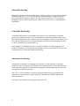
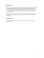
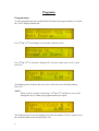
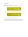
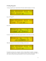
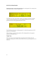
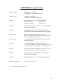
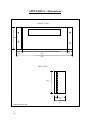
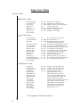
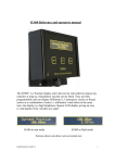
“GO 2” USER MANUAL
Contents
General Operation
Power Up
Keyboard functions
Manual Positioning
Controlled Positioning
Cut’s Counter
3
4
4
5
5
6
Programs
Entering Programs
Editing Programs
Clearing Programs
Running Programs
8
10
11
12
Operators Menu’s
Recalibrate
Set Calibrate Position
View Total Cuts
Display Cuts
False Clamp
Change Precision
13
13
14
14
14
14
Appendix A – Connections & inverter settings (E520 + ATV11) 15 - 20
Appendix B – Messages and Actions
22
Appendix C – Troubleshooting
23
Appendix D – Specifications
26
Appendix E – Dimensions
27
Menu Structure
Operator menu
Supervisor menu
Engineer menu
28
29
31
Installation
2
Installation
Auto install guide
Installation Tips
Functions in Brief
32
35
40
42
Service & Support
43
General Description
The IC1600 “GO 2” unit is a multifunction position control system that has been
designed for use on any backgauge or gauge assembly that can be fitted with a rotary
encoder and is capable of being driven by a motor, typically a leadscrew type
assembly.
The installation and Setup has been made easy by utilising screw terminal connectors
and RJ45 plugs and sockets, the standard unit can be software configured to work
with a wide range of control types, AC Inverter, DC Drives and 2 speed motor via
contactors.
The menu structures allow each unit to be Setup to customers specific requirements or
machine requirements these include acceleration and deceleration times, minimum
and maximum speed, units displayed etc.
The “GO 2” unit has a wipe clean membrane style keypad with tactile feel with
confidence beep for each key press and is housed in a rugged custom extruded case,
the display is a large format 2 x 20 backlit LCD module with excellent contrast and a
wide viewing angle thus allowing mounting of the “GO 2” unit above or below the
operators eye line.
Support is given for a wide range of Encoders unlike other systems the “GO 2” uses
the actual number of Pulses Per Rev (PPR) and the Pitch to obtain its accuracy and
not a pre–scaler, the “GO 2” unit also caters for a wide range of power supplies to
enable quick and easy replacement of existing displays or faulty controllers.
The “GO 2” unit has been designed using some of the latest proven technology
combined with surface mount components offers a package that is flexible, reliable
and cost effective, the firmware is fully upgradeable at any time by simply plugging a
programmer in and downloading the latest version of code should the need arise, no
chips to remove, thus maintaining the overall system integrity.
The “GO 2” system also has an Auto install menu that guides the installer through all
the settings necessary to get the unit up and running, once the auto install has been
executed the engineer can use the supervisor menu to fine tune the system see page 35
3
GENERAL OPERATION
Power up
At switch on the “GO 2” unit will run through a self test procedure, this is to ensure
that any programs or configuration data that is held in none volatile memory is intact
and ready for use, during this sequence of self testing information about the unit will
be displayed, this includes the software version and date, and manufactures
information.
After the configuration has been loaded the firmware version is displayed
On completion of the self-test the “GO 2” unit will prompt the operator to ensure that
the backgauge is clear and press GO (assuming it is safe to do so)
The backgauge will now move in slow speed towards the rear of the machine and stop
at the calibrate point then move forward to remove any backlash from the system
On completion the current position will be displayed (with cuts if enabled)
4
Keyboard
The keyboard is a standard format tactile membrane with key press confidence beep’s
to advise the used on each key press, it is split into 2 areas “function buttons” and
“numeric input”
Function buttons
This button allows the user to enter an offset from the current
position, for example the current position is 573.5 mm the next
cut is 56 mm less (517.5) instead of calculating the required
position use offset, press +/ – enter 56 and press GO.
The unit button selects the unit of measurement mm, cm inches
and so on it also allows the user to access the Operator Menu, to
enter the Operators menu press and hold the unit button until the
display reads “Operator Menu”.
The Del (Delete) button is used to perform 2 functions firstly it
allows the user to delete / remove any incorrect numeric entry
and secondly it acts as a back / exit button during program entry
and within the menu structure.
The “/\” and “\/” buttons are used to manually
move the backgauge, the first 3 seconds is a
slow speed move or nudge after 3 seconds the
backgauge will accelerate to full speed, they
are also used as scroll buttons in menu’s
The GO button has 2 functions, it acts as an enter button to accept
an input or dimension e.g. 200 GO will position to 200, the second
function of the GO button is to enter program mode. To enter
program mode press and hold until the display shows the program
screen see page 8
The Decimal Point button has 2 functions the first and primary
function is to all entry of fractions if units i.e. 0.5 mm it’s
secondary function if pressed and held will produce a pushout
Movement then return to the previous position
5
Manual Positioning
Manual positioning is the most basic move, simply press the /\ to move the backgauge
backwards and the \/ to move the backgauge forwards when the nudge buttons are
first pressed the backgauge will move in slow speed if held for over 3 seconds the
backgauge will accelerate to full speed, useful if you need to move several hundred
millimetres
Controlled Positioning
Controlled Positioning is a backgauge movement to a pre determined or absolute
position, say 500 mm, to move to a pre determined or absolute position simply enter
the required dimension (500) and press GO, the backgauge will now re position to 500
units, the operating units are set by pressing the units button, any backgauge position
or move is displayed in current units e.g.
If the display is in millimetres (mm) if you press 500 then GO the backgauge will
position to 500mm, if the displayed unit is Inches and you enter 500 then GO the unit
would position to 500 inches (machine allowing)
Automatic Positioning
Automatic Positioning is a backgauge movement to a predetermined or absolute
position by way of program, the program will contain a number of cuts and positions
as the cuts and positions are achieved the backgauge will automatically step onto the
next position within the program.
The “GO 2” unit is capable or storing 9 programs with 99 steps per program, the
programs are stored in non-volatile memory so that they are retained after power
down and restart.
See Page 8 for information on program entry and edit.
6
Cuts Counter
The “GO 2” unit contains 2 cuts counters, one counter stores the number of cuts at the
current position, the other cuts counter stores the total number of cuts since the “GO
2” unit was installed, Total cuts can be used to determine the number of cuts that a
knife has performed before each knife change thus giving an indication of when the
next knife change may be due or indicating which type of knife is best suited to the
material being cut.
The total cuts counter can also be used to obtain usage or machine throughput figures
so that work can be allocated to specific machines as required and to aid in work
distribution.
Resetting Cuts
If for any reason the Cuts displayed needs to be reset to 0, press the zero button
followed by GO
7
Programs
Program entry
To enter program mode press and hold the GO button, after approximately 3 seconds
the “GO 2” display should read
Use “/\” or “\/” if the display is not as above then Press GO
Use “/\” or “\/” to select the “Program No” to create, in this case it’s No 1, then
press GO
The flashing cursor indicates the area in use, in the above case the Step number,
Press GO.
NOTE
When you have entered several steps “/\” or “\/” will allow you to scroll
through the step’s within your program should you require.
The flashing cursor is now prompting you to enter the number of Cut’s required, once
the required number has been typed press GO
8
The flashing cursor will now be prompting you to enter the position that you require,
as with cut’s type the required position then press GO
You have now entered the first step in your program, the flashing cursor will now
return to the Step area, use the “/\” or “\/” buttons to advance the step number and
repeat the above procedure until the full program is entered then press DEL to save
and exit from the program. The display will return to: -
If you need to enter another program or review the program just entered press GO if
you want to exit and go back to you running screen press DEL
If you require a pushout within a program you must enter it as a step but ensure that
the cut’s are left at zero, when the backgauge reaches position it will stop for a
fraction of a second then move onto the next step within the program and wait for the
required number of cuts.
9
Program Editing
Editing a program is very much the same as program entry press and hold the GO
button until the screen is as below
Press GO
Use “/\” or “\/” to select the program to edit and press GO
The screen format is exactly the same as program entry, use the GO button to save
and move the flashing cursor to the next area to edit, type the new cuts or position and
press GO, once you have completed the changes press DEL twice to save and exit
10
Clearing Programs
To clear programs press and hold the GO button until the display is as below
Press “/\” or “\/”
Press GO
Use the “/\” or “\/” to select the program number to clear then press GO
When the program has been cleared to display will revert to
If required you may enter a program, we have assumed that if you delete a program
that the next logical step is to enter a program to replace the one deleted, press DEL if
you want to return to the normal run mode or GO to create the new program
11
RUNNING PROGRAMS
Running programs is simple and straightforward, to run program 2 for example press
and hold the number 2 until the display reads
The display now shows that you have opted to run program 2 and that it contains
2 steps, to run the program press GO; the backgauge will now move to its first
position and wait for the programmed number of cuts.
The P2 indicates that you are running program 2, to abort the program press ANY
numeric key (0 through 9)
When running a program the Step number will be displayed below the program
number (not illustrated above)
Single Step
If for any reason you need step through a program use the GO button once the
program is running, this will allow you to break off from one job and go back to it as
and when.
12
OPERATOR MENU
The operator menu contains several functions that may be needed once the unit has
been installed, to gain access to the operators menu press and hold the units button
after 3 seconds the top line or the display will read “operator menu”
To scroll through the menu use the “/\” or “\/” buttons until you see the appropriate
menu then press GO to enter or execute the command. To Exit from any menu use the
DEL button.
Recalibrate
Recalibrate will reset the backgauge to it’s correct position as at switch on, if for any
reason the Backgauge is incorrect after a recalibrate use “Set Calibrate Position” to
correct the error. To recalibrate press GO from operator menu / recalibrate you will
then be prompted to ensure backgauge is clear, if it’s safe to move the backgauge
press GO, the backgauge will now recalibrate itself.
Set Calibrate Position (Press \/ x 1)
Set Calibrate Position will correct any error between the displayed position and actual
backgauge position, to use this function you will need either a good ruler or if
possible Vernier Calipers, when Set Calibrate Position is entered you will be
prompted
Press GO, this moves the backgauge onto the calibrate switch
13
Once the backgauge has reached the calibrate switch it will stop and prompt
At this point you must move the backgauge forward perform a cut and measure the
material just cut, enter that dimension and press GO to complete the operation
View Total Cuts (Press \/ x 2)
This option will allow you to View the total cuts made to date
since the installation of the unit
Display Cuts
(Press \/ x 3)
Allows the “Cuts” to be displayed, if the “Cuts” display is not
required simply select “NO” when prompted
False Clamp
(Press \/ x 4)
This option allows the use of a false clamp, if the “False
Clamp” is fitted the minimum position is changed to ensure that
the backgauge will not hit the false clamp when positioning
Change Precision (Press \/ x 5)
Allows the number of places after the decimal point to be
selected, the defaults should be set at the time of installation
Pressing DEL from the operator’s menu will return to the operating mode.
14
APPENDIX A - Connections
Common connection point for forward, reverse and slow
Forward relay
Reverse relay
Slow relay
Brake relay to slave relay or contactors
Common connection for Knife & clamp switches
Knife switch input
Supply for Knife & Clamp switches (if proximity type)
Clamp input
Voltage Command Signal Common
Voltage Command Signal (analogue output)
Encoder connection Via RJ45 cable and inter connection
box (Page 16)
+ 9v DC Input
Common or 0v Input
Fit link for single supply
Operation at 15v DC
+ 15v DC input
Note
Common or 0v input can if required be connected to system Earth, the “GO 2” unit is
floating because of power supply isolation in certain environments this is not
desirable and so an Earth reference may be added if required.
15
Connections (Continued)
The Encoder and Calibrate switch are terminated within the interconnection unit
shown below, all the screw terminals are clearly marked and should be connected as
pictured below,
Encoder + Calibrate switch connections
Calibrate
Proximity
Calib.
Quad A
Earth
Quad B
Earth
Ref in
Earth
+12 v
British Encoder
WHITE
RJ 45
Note
The Earth terminal is NOT a true Earth it is the system Earth only
16
Connections (Continued)
The drive connections will vary for installations depending on the existing control
panel or if a complete panel is being replaced we have included interconnection
information for a Mitsubishi E520 inverter for guidance as it can be supplied as part
of the complete kit if required
GO2 unit
Inverter
Relay Common
SD ( sink )
Forward Relay
STF
Reverse Relay
STR
Analogue Common
Terminal 5
Analogue Output
Terminal 2
In order to use the SD terminal ensure that the selection link is set to SINK, if the link
Is in the SOURCE position the PC terminal may be used
Motor / Brake Connections
If the motor has been supplied pre wired as part of the kit it will be wired as detailed
below.
1
2
MOTOR
240v
BRAKE
3
4
5
Gr / Ye
17
E520 Inverter Settings
If the inverter has been supplied as part of the GO2 kit I will have been programmed
as follows.
PR 0
PR 1
PR 2
PR 3
PR 7
PR 8
PR 9
TORQUE BOOST
MAX FREQUENCY
MIN FREQUENCY
BASE FREQUENCY
ACCELERATION
DECELERATION
RATED MOTOR CURRENT
15 %
55HZ
0 HZ
55HZ
0
0
3.4 A
PR 71
PR 72
PR 73
APPLIED MOTOR
PWM FREQUENCY
VOLTAGE IN SELECTION
106
6
1
PR 80
PR 83
MOTOR CAPACITY
MOTOR VOLTAGE
0.75 Kw
230 V
PR 96
TUNING
0
PR 156
STALL PREVENTION
2
18
ALTIVAR SERIES INVERTERS
Connections for the Altivar ATV11 / ATV12 & ATV312 inverter are as follows
RC
GO2 unit
RA
N/C
Analogue Common
0V
Analogue output
A1 Analogue in
+5V
*Limit Switch
DO
Forward Relay
LI 1 Forward
Reverse Relay
LI 2
Reverse
LI 3
LI 4
Relay Common
+ 24V common
*Limit switches are not necessary as the GO2 unit has software limits, but may be
fitted for a true mechanical limit
E L N ( 240v mains input )
U V W ( To motor )
19
ATV 11 Inverter Settings
The inverter parameters below are typical starting point settings, the inverter can be
fine tuned to give best performance.
To edit current values displayed on the inverter use “\/” and “/\” to increment and
decrement, then enter by pressing and holding the “ ENT ” button until the display
flashes once.
From the “ rdY ” prompt on the inverter, use “ \/ ” and “ /\ ” to scroll if required
Press “ \/ ” x 1
bFr
ACC
dEC
LSP
HSP
ItH
AIt
Motor Frequency
50 Hz
Acceleration
0.1s
Deceleration
0.1s
Low Speed
0.0 Hz
High Speed
50 Hz
Amp rating on motor plate
Analogue input
IOU
Press ESC then “ /\ ” x 3 to drC
UnS
FrS
StA
FLG
UFr
nCr
nSL
SLP
COS
Motor Voltage on plate
Frequency
Loop Stability
Loop Gain
IR Compensation
Set as ItH above
Motor Slip
Slip Compensation
Nominal Cosine
230v
50 Hz
20 %
60 %
150 %
0%
0%
0.77
Press ESC then “ \/ ” x 1 to FUn
tCC
rrS
brA
Control Type
2C
Reverse
L12
Deceleration Adaptation NO
Press “ ESC ” x 2 to return to rdY
All other settings are as factory default, for detailed information on the inverter
settings please refer to the Altivar 11 manual as supplied with the inverter.
20
ATV 12 Inverter Settings
To edit current values displayed on the inverter use “JOG dial” to increment and
decrement, then enter required value by pressing the “JOG dial” until the display
flashes once.
From the “ rdY ” prompt on the inverter, use “JOG dial” to scroll to required menu
Scroll to display “CONF” press “JOG”
bFr
ACC
dEC
LSP
HSP
nCr
Motor Frequency
50 Hz
Acceleration
0.1s
Deceleration
0.1s
Low Speed
0.0 Hz
High Speed
50 Hz
Amp rating on motor plate
Scroll to display “FULL” press “JOG” then scroll to drC and pres “JOG”
COS
nCr
FrS
nSP
UFr
SLP
StA
FLG
UnS
Nominal Cosine
Set as nCr above
Frequency
Speed on motor plate
0.77
50 Hz
1440 if 4 pole
2880 if 2 pole
IR Compensation
150 %
Slip Compensation
0%
Loop Stability
20 %
Loop Gain
60 %
Motor Voltage on plate 230v
Press ESC then “ JOG” to Fun and pres “JOG”
rrS
brA
Reverse
L12
Deceleration Adaptation NO
Press “ ESC ” and return to rdY
All other settings are as factory default, for detailed information on the inverter
settings please refer to the Altivar 12 manual as supplied with the inverter.
21
ATV 312 Inverter Settings
To edit current values displayed on the inverter use “JOG dial” to increment and
decrement, then enter required value by pressing the “JOG dial” until the display
flashes once.
With the “rdY” prompt on the inverter, use the “JOG dial” to scroll to required menu
then press the “JOG dial” to enter.
Scroll to display SEt
ACC
dEC
LSP
HSP
ItH
UFr
FLG
StA
SLP
Acceleration
Deceleration
Low Speed
High Speed
Amp rating
IR Compensation
Loop Gain
Loop Stability
Slip Compensation
0.0s
0.0s
0.0 Hz
50.0 Hz
A*
50 %
50 %
20 %
0%
Press ESC then to drC
UnS
FrS
nCr
nSP
COS
UFt
Nrd
SFr
Motor Voltage
Frequency
Set as ItH above
Nominal Speed on motor
Nominal Cosine
Motor selection use
Random switching
Switching Frequency
230v *
50 Hz *
RPM *
0.77 *
L or P
No
6 Khz
Press “ ESC ” until rdY is displayed
All other settings are as factory default, for detailed information on the inverter
settings please refer to the Altivar 312 manual as supplied with the inverter.
* See information on motor plate
22
APPENDIX B - Messages and Actions
Message
Action
Ensure Backgauge is
Clear and press GO
If it is safe to move the backgauge
press the GO button the backgauge will
Now move to a pre determined position
ERROR
NOT INSTALLED
This message will be displayed if either
the unit has not been Setup of if the
configuration has become corrupt you must
go through the install procedure
ERROR
M/C STALLED
The backgauge has not moved or the encoder
has failed; check that the backgauge is free to
move and that any couplings are tight also
check the Stall Samples value in the supervisor
menu (if installing)
ERROR
Knife Error
An attempt was made to move forward whilst
the Knife was down; check the knife position
of the Knife is at TOS check the switch
ERROR
Clamp Error
An attempt was made to move forward whilst
the Clamp was down; check the position of the
Clamp also check the Clamp switch
Range Error
An attempt was made to enter a dimension
that is less or greater than the machine limits
or incorrect units e.g. 50 inches instead of 50 mm
23
APPENDIX C – Troubleshooting
Problem
Reason & Action
Display illuminated and the
Beeper sounds continuously
The “GO 2” unit has not reset at
switch on remove the power for
10 seconds then switch back on
I enter a dimension but the backgauge
does not move.
The dimension entered was
outside the machine limits, check
the current unit’s mode (mm, cm)
Unit will not display inches
Check advanced Config to see
if they have been enabled
The backgauge moves forward but
the display counts up
The encoder needs reversing in
Config, or Quad A and B need
swapping over
Cuts are not displayed
Go into operators menu and
select display cuts “Yes”
My machine has 950mm of travel but
I can only position to 940mm
To ensure that backlash is
removed from the backgauge it
will position from one direction
the overshoot can be adjusted in
the supervisor menu but should
be ½ the pitch if possible
24
Troubleshooting (Continued)
Display shows Move encoder through
180 degrees
The encoder reference pulse and
Calibrate switch are too close
together, turn the encoder and set
Calibrate position (page 13)
The backgauge is correct at 900mm
but 1mm out at 400mm and 2mm out
at 100mm
This would suggest that the PPR
Or the Pitch is set incorrectly
I have got a black square on the left
Side of the display
Display Max speed is enabled
K or C are displayed all the time and
I cant move the backgauge forward
K of C on the display are
advising that the Knife or Clamp
are down, to move forward would
be unsafe so it is disabled,
reverse is allowed for clearance
Check ths switches for K & C
F displayed on top line of the display
The “F” indicates that the False
Clamp is enabled and will not
allow the operator to position to
the minimum dimension
I can’t position to less than 100mm
Either the machine limit has been
set incorrectly or the False clamp
has been enabled in operator’s
menu
“C” is not displayed even when the
Clamp is down
This suggests that the Clamp
option is set to None see Machine
Config Page 25
25
Troubleshooting (Continued)
When I run a program the first position
is ok but the unit will not step on to the
next position unless I press GO
The GO2 is looking for a change
of state on the Knife + Clamp
switch and only seeing one of
them (Knife or Clamp) look for
K or C on the display when cutting
to determine which is missing then
check the Machine Config to
correct.
Also
Check the Knife and Clamp
switches, are they in range and
working
The backgauge keeps hunting around
Position
Several parameters can cause the
Backgauge to hunt around
position check the slow speed
and tail length also check the
mechanics as they are often the
cause of problems (clean &
WD40)
The backgauge continues to hunt around
Position after cleaning
If the inverter is setup as per
page 20, 21 & 22 try changing
the motor type to “Special motor”
For ATV12
drC > Ctt >
PErF
Std
( default )
PumP ( Try )
For ATV312
drC > UFt >
L
P
N
26
( Try )
( default )
APPENDIX D - Specifications
Supply Voltage
Single supply 15v DC**
Twin supply 9v DC and 15v DC **
Supply Current
< 400 ma for unit alone
< 600 ma with encoder and sensors
Display
Large format 2 x 20 LCD with LED backlight
Metric Resolution
mm to 2 dp.
Imperial Resolution
inches to 3 dp.
Enclosure
Custom extruded section epoxy coated in “Ford Black”
with mild steel brackets
Keypad
Membrane keypad with embossed keys and highly
tactile Stainless Steel domes and hardwearing overlay
Encoder Input
Opto isolated inputs to suite most encoders
NPN, TTL, Push-Pull and Line Drive that will operate
At 12V DC and provide A + B + Z
Switch Inputs
3 x Switch inputs suitable for either contact or NPN
proximity switches
Outputs
3 x common’d Relay’s rated at 1A 250 VAC
1 x Volt free contacts for operation of brake slave relay
1 x Analogue (0 to 10v DC) or (–10v to +10v DC)
Memory
Ferroelectric Ram with retention in excess of 10 years
without loss of data ( 1 billion write cycles)
Hardware
8 Bit microprocessor with 64K Flash, 2K Eeprom
1K Ram with I2c and ISP
Firmware
Fully upgradeable by use of In System Programmer
Manufactures Warranty
12 months, return to base
** See Connections in Appendix A
27
APPENDIX E - Dimensions
FRONT VIEW
140
22
251
22
295
SIDE VIEW
140
7
7
40
47
Dimensions in mm
28
MENU STRUCTURE
The “GO 2” unit contains 3 menu structures: 1) The operator’s menus, used in day-to-day operation
2) The Supervisor menus, used to change or correct parameters
3) The Engineers menu, used for installation
To access the menu’s press and hold the DEL button until the display changes to
“CHOOSE MENU” then use the “/\” or “\/” to scroll to the required menu and press
GO to select and enter.
The Supervisor and Engineer menus are protected by passwords to prevent accidental
changes to parameters within the menus; we strongly recommend that you DO NOT
change parameters unless you fully understand the implications of your actions.
The Supervisor Password is 9999 and GO to enter
The Engineer Password is 1600 and GO to enter
Once you have entered the Supervisor or Engineer’s menu the \/ and /\ buttons are
used to scroll around once a sub menu is entered use DEL to take you back to a
previous item and GO to accept the data displayed and move on to the next item, once
the end of the menu has been reached you have the option to save the changes Yes
saves No restores the previous contents.
Operator menu
Recalibrate
Set Calibrate Position
View Total Cut’s
Display Cut’s
False Clamp
Change Precision
Resets the backgauge as at power on
Corrects gauge position if incorrect
Displays total cuts to date
Allows cuts to be displayed
Allows use of False Clamp offset
Adjusts No. of decimal places shown
29
Supervisor Menu
Supervisor Menu
Simple Config
Reverse Encoder
Encoder P P R
Screw Pitch
Default Units
Snap To
Snap Tolerance
Display Cuts
Save Changes
Yes / No
0 – 1000
0 – 25mm
mm
Yes / No
0 – 99mm
Yes / No
Reverses Count direction
Pulses Per Rev of the Encoder
Effective pitch of screw and gearing
Powers up into mm
Display rounding at position
Tolerance of rounding + / Display cuts if required
Position Setup
Position Retries
Position Tolerance
Min Move
0–5
No. of attempts at any position
0 – 10mm Position tolerance + / 0 – 99mm Smallest forward move without
reversing the backgauge first
Reverse Overshoot
0 – 99mm Overshoot when approaching position
Auto Reposition
Yes / No If position fails automatically retry
Drift Tolerance
0 – 99mm allowable drift before reposition made
Brake To Stop
Yes / No Use the brake to aid stopping
Brake On Stop
Yes / No Use the brake to aid position holding
Brake On For
0 – 99 S Used if pulsed brake is required
Stall Samples
0 – 999
Stall detection in milliseconds
Pushout
0 – 999
Distance to pushout by
Efficiency***
0 – 100% Effective efficiency of mechanics
D2A Up Damping***
0 – 128
No. of steps to accelerate to full speed
D2A Down Damping *** 0 – 128
No. of steps to decelerate to stop
Save Changes
Machine Config
Is Knife Up
Is Clamp Up
Is Calibrate Clear
Is Brake On
Minimum Size
Maximum Size
Min Slow Zone
Max Slow Zone
False Clamp
Tail Length
Slow Reverse
Slow Forward
Fast Reverse
Fast Forward
Slow Nudge
Save Changes
Yes / No
Yes / No
Yes / No
Yes / No
Used for switch level detection
Used for switch level detection
Used for switch level detection
Sets relay state for brake
Minimum position to drive to
Maximum position to drive to
Force slow speed before Min size
Force slow speed before Max size
Position of/fset if FC is fitted
Distance in slow speed for positioning
Slow speed in reverse direction
Slow speed in forward direction
Fast speed in reverse direction
Fast speed in forward direction
Nudge speed ( \/ or /\ )
*** See graphs in Installation and Setup
30
Supervisor Menu (Continued)
Advanced Config.
Reverse Encoder
Encoder P P R
Screw Pitch
Default Units
Snap To
Snap Tolerance
Display Cuts
Enable mm
mm Precision
Enable cm
cm Precision
Enable Inches
Inches Precision
Enable 1/inch
1/inch Precision
Enable Dual Units
Dual Unit 1
Dual Unit 2
Enable Pulses
Enable Debug
Show Speed
Show Max Speed
Save Changes
Yes / No
0 – 1000
0 – 25mm
mm
Yes / No
0 – 99mm
Yes / No
Yes / No
0 – .00
Yes / No
0 – .000
Yes / No
0 – .000
Yes / No
½ to 1/64
Yes / No
Yes / No
Yes / No
Yes / No
Yes / No
Reverses Count direction
Pulses Per Rev of the Encoder
Effective pitch of screw and gearing
Powers up into mm
Display rounding at position
Tolerance of rounding + / Display cuts if required
Allow mm to be displayed
No of decimal places
Allow cm to be displayed
No. of decimal places
Allow inches to be displayed
No. of decimal places
Allow Fractal inches to be displayed
Fractal size minimum
Allow 2 units displayed on 1 screen
Unit to be displayed on top line
Unit to be displayed on bottom line
For debug only
For debug only
Display bar graph of current speed
Display peak speed on left of display
31
Engineer Menu
Engineer Menu
Auto Install
The Auto Install routine guides you through the installation
process to allows the GO 2 unit to run, though we recommend
fine tuning via the supervisor menu.
Check FRAM
Check FRAM performs 2 tests to check the integrity of the
Feroelectric Ram
Overrun Mapping
Overrun Mapping breaks the leadscrew up into 2000 divisions
or Zones each Zone is then given an overrun value during
positioning this allows the leadscrew to be mapped to ensure
that positioning remains constant even if the leadscrew is worn
and contains tight spots.
If the overrun mapping is disabled a single value is used for the
entire leadscrew assembly.
Reset Overruns
Resets the entire overrun table, used if repair work has been
undertaken that dramatically affects the mechanical properties.
Reset Total Cuts
Resets the Total Cut counter to 0000
Clear All Programs
Deletes all the programs and resets the program memory
Factory Default
Factory Default restores all the factory settings for ALL
parameters in ALL menu structures but does not delete the user
programs, after a factory default the “GO 2” will prompt “NOT
INSTALLED” and will need reinstalling from Auto Install
Debounce Input
If proximity inputs are subject to noise and cause false
triggering increase the debounce time in multiples of 10ms
32
SENSOR INSTALLATION
The installation procedure has been kept simple and logical to allow any competent
engineer to install and commission a system in less than a day.
Sensor Installation
Correct installation of the sensors is critical for trouble free operation please take time
and care to ensure that the sensors are properly fitted in the best possible place.
Encoder
The encoder must be mounted rigidly and driven by way of belt, chain or flexible
coupling and mounted in a position that will provide some protection, the cable
should be secured and wherever possible routed away from sources or electrical noise.
The Calibrate Switch
The Calibrate switch must be mounted towards the maximum travel but in such a
position that the backgauge or gauging mechanism will never run off the switch see
diagram below
Max. travel
Travel
Calibrate
Switch
Leadscrew
A) WRONG
B) Correct
As can be seen from diagram A) when the backgauge or gauging mechanism reaches
it’s maximum travel it will no longer be on the calibrate switch, this will cause a
failure at calibrate. At switch-on the “GO 2” unit will move backwards to find the
calibrate switch then come forward one revolution to find a reference pulse from the
encoder, in diagram B) the calibrate switch is correctly positioned allowing some
overrun but never allowing runoff.
33
Knife and Clamp Switches (if applicable)
The Knife and Clamp sensors should be fitted so that when the Knife or Clamp begin
to move the switch sees the movement, the “GO 2” unit will NOT position in a
forward direction if the Knife or Clamp are down or the switch has been seen, this
ensures that the material being cut or bent will be stationary and operators hands away
from the material.
Knife Switch (correct position)
Start
Motion of blade
Finish
Knife Switch (Incorrect position)
The Knife and Clamp will also act as step change inputs whilst running a program if
you do not intend to run programs and do not wish to inhibit forward movement when
the Knife or Clamp are down these switches can be left unfitted, though we strongly
suggest that they are.
Note
If the Clamp option is set as NONE the position inhibit and step change will occur on
Knife only
34
AUTO INSTALL SETUP
Once the “GO 2” unit and sensors have been installed, checked and verified power
can be applied, the “GO 2” unit will go through a self-test procedure and then prompt,
“ERROR NOT INSTALLED” followed by the Engineers mode,
Press GO
Type 1600 then press GO
The display will now be showing “Auto Install” if not use /\ or \/ to scroll
Press GO
The screen will now display “Resetting Overruns” this clears out any mapped data
ready for installation.
Language, select ENGLISH by pressing GO
The drive type is now shown, INVERTER is the default, use the /\ or \/ buttons to
change if required, options are RELAY for 2 speed motor driven by contactors and
DC for use with servo drives and drives that require +/- 10v velocity signal.
Press GO to enter
Is Knife UP ?
use /\ or \/ to select YES or NO then press GO
Is Clamp UP ?
use /\ or \/ to select YES or NO or NONE if no clamp switch fitted
then select NONE then press GO
Is Calib Clear ?
Is the calibrate proximity switch clear of the backgauge or not ?
use /\ and \/ to select YES or NO then press GO
Is Brake on ?
use /\ and \/ to select YES or NO then press GO
Minimum
Smallest size that you allow the Backgauge to come in to, enter a
value then press GO
Maximum
Largest size that you allow the Backgauge to come in to, enter a
value then press GO
Min Slow
Creates a slow zone at the “front” of the backgauge to prevent the
operator hitting the minimum size at full speed and jamming the
backgauge when nudging, typical size would be minimum + 50mm
Max Slow
Creates a slow zone at the “rear” of the backgauge to prevent the
operator hitting the maximum size at full speed and jamming the
backgauge when nudging, typical size would be maximum - 50mm
35
F.Clamp
Used on paper cutting machinery, creates a temporary minimum size
to prevent the backgauge hitting the false clamp. Measure your false
clamp and enter that size if NO false clamp leave at 0mm
Tail length
The tail length is the approximate distance at the bottom of the
deceleration curve where the backgauge is at a steady slow speed
a starting point is 1.5 or 2 x the leadscrew pitch.
Slow Reverse
Determines the slow reverse speed 10% generally very close to
correct value and can be changed later if required
Slow Forward
Determines the slow forward speed 10% generally very close to
correct value and can be changed later if required
Fast Reverse
Determines the maximum reverse speed this value can be changed
later if required
Fast Forward
Determines the maximum Forward speed this value can be changed
later if required
Slow Nudge
Typically set slightly higher than slow speeds, used for manual slow
nudge speed and for the calibration speed
Centre Backgauge and press go
By using the nudge buttons /\ or \/ you can check that the backgauge will actually
move and that the direction is correct, the backgauge should move forward when \/ is
used and backwards when /\ is used, on pressing GO the backgauge will move
through 1 rev to check the encoder and direction, as long as the backgauge moves
forward press GO to accept
Encoder PPR
The detected pulses per rev are displayed if this is not correct enter
the new value then press GO the encoder supplied is 360 ppr
Calibrating backgauge centre machine then press go
Ensure that the backgauge is away from the calibrate switch, towards the centre of
travel, use /\ or \/ to move then press GO the backgauge will now move at slow speed
in reverse to the calibrate switch, then stop and move forward OFF the calibrate
switch and stop.
If at this point you have a calibrate AND encoder reference pulse at the same time you
will be prompted to rotate the encoder through 180 degrees to correct then press GO
36
Move away from calibrate switch to known position
Place a tape measure from the cut line to the backgauge and move forward using
either a hand wheel if fitted or by using the \/ button. Move to a convenient whole
number i.e. one that is easy to read say 890 as opposed to guessing that its 896.
something accuracy is critical so DO NOT reverse the backgauge during this process
as it will introduce backlash errors.
Move away again to another known position
Move the backgauge forward again towards the front of the machine and take a
second measurement from the cut line to the backgauge. This allows the “Go 2” unit
to calculate the effective pitch of the leadscrew as seen by the encoder
Example
First measurement
890 mm
Second measurement 200 mm
Distance travelled
690 mm
As the PPR of the encoder is known we know exactly what the pitch is.
As the second position is entered the display will change to show the calculated pitch
and the calibrate position, if for any reason the pitch calculation looks very wrong use
the DEL button to step backwards and repeat the previous 2 steps
Press GO to accept and continue
Position Retries
This is the number of times that the “Go 2” will attempt to
obtain position before aborting
Position Tolerance
Set to 0.1mm for most applications to give a position of
Target +/- 0.1mm
Minimum Move
A confusing parameter…if a backgauge is in good order and
does not suffer from tight spots it can be moved small amounts
easily however if the backgauge is not “ideal” moving small
amounts can be difficult, to prevent stalling and failed position
attempts the minimum move parameter can be set higher set at
3 to 5 mm suites most relay setups and 1 to 3 mm for inverter
and servo’s
Reverse Overshoot
As we always position in one direction to remove backlash the
reverse overshoot value is typically the distance that we go past
out target by before coming forward onto target, starting point
is approx 2 x pitch
Auto Reposition
if the backgauge is knocked off position do you want to
automatically reposition use drift value to set tolerance
37
Drift Tolerance
this is the amount that the backgauge can be moved away from
the target position before it will automatically reposition if auto
is ON, typically set at tolerance + .05 mm so 0.15 mm
Brake to stop
If you have a brake motor do you want the brake to assist in
stopping the backgauge for positioning
Brake on stop
when the backgauge has positioned do you want to apply the
brake ? this can also be used as inhibit so that the machine
cannot be cycled if the backgauge is moving
Brake on for
if brake to stop is used this sets the duration of braking
Stall Samples
Stall detection, leave at 250
Pushout
only used on paper cutting guillotines to push work forward
after a cut has been made to prevent operator reaching under
blade to move work, set at 0.00 for all other applications
Efficiency
sets the deceleration ramp, if possible leave at 10%
Speed
Max speed
E=10%
E=20%
Target Position
Distance
The efficiency setting will effect the speed of positioning quite dramatically, if the
backgauge or application has a high inertial load it will take longer to stop than a
system with virtually no inertial load, by setting the efficiency to 10%, the default,
the stopping time and distance are relatively long and smooth if the efficiency is
changed to 20% the deceleration distance will halve as will the time to decelerate,
By adjusting the efficiency the system can be Setup to suite any application
regardless of the size or speed and tuned to give the fastest response, if the efficiency
is set too high you are in effect creating a vertical deceleration ramp which will lead
to excessive strain on all associated components and may prevent positioning
38
D2A UP Damp
if set to 1 provides smoother acceleration the larger the value
the more aggressive the acceleration best set between 1 and 3
D2A Down Damp
if set to 1 provides smoother deceleration the larger the value
the more aggressive the deceleration best set between 1 and 3
Save Changes
press GO to save all your settings
The Go 2 will now update the configuration and exit to engineers menu press DEL to
exit into operating mode
If during the install procedure you suspect an incorrect value has been saved these can
now be corrected from within the Supervisor menu.
At this point it is worth checking that the position displayed is correct then move to a
mid position on a 1m machine use 500mm, the backgauge may hunt a couple of times
until it has calculated its overruns, measure the position then move further forward to
say 50mm at this dimension perform a cut or bend to establish the actual size, if the
size is incorrect adjust using the “Set Calibrate position” on Page 13 then recheck.
The Go 2 unit creates a map of the leadscrew, when the installation is complete try
several positions 700, 600, 500, 400, 300 after attempting these positions valid data
should be in the lookup table and should enable positions to be achieved first time.
If positioning is poor check slow speed values, tail length and efficiency.
39
INSTALLATION TIPS
Every installer will undoubtedly have their own preference as to system installation
we have provided this section simply to pass on some of our findings whilst
installations have been carried out
An understanding of the menu structure is not necessary but will enable you to get the
most out of the system and fine tune it to your customers requirements and in most
cases far beyond.
1) Mount the “GO 2” unit on the machine (drill + Tap 4 x M4 holes)
2) Remove the unit and re fit the right hand bracket only on the machine.
The right hand bracket has a 20mm hole for a conduit gland
3) Fit the Encoder and Calibrate switch and wire into the small black
interconnection unit then route the RJ45 cable up towards the “GO 2” unit.
4) Now fit the Knife & Clamp Switches (if required) and the power supply and
again route towards the “GO 2” unit
5) Slide the cables through the flexible conduit provided RJ45 FIRST see Note *
6) Terminate the cables as required and finally insert the RJ45, now carefully
draw back any excess cable so that the “GO 2” sits in place and press home
the gland on the conduit.
7) Refit the “GO 2” enclosure and secure to the machine and secure the conduit
Note :
To reduce the number of cables taken to the GO 2 unit use 12 core screened cable to
run from the existing machine control panel, within the 12 cores include power to the
GO 2 along with relay outputs and switch inputs, using this method allows the
installer to run 2 cables to the GO 2, 12 core & RJ45 cable
You are now ready to Setup your system
40
INSTALLATION NOTES
41
FUNCTIONS IN BRIEF (CHEAT SHEET)
“\/” OR “/\”
MOVES GAUGE FORWARD OR REVERSE
UNIT
CHANGE MM TO CM TO INCHES ALSO
PRESS AND HOLD FOR OPERATOR MENU
DEL
DELETE BUTTON AND EXIT PROGRAM
“.“
DECIMAL POINT OR PUSHOUT (Hold in)
GO
PRESS AND HOLD TO ENTER PROGRAM
MODE
XX THEN GO
MOVES TO POSITION XX
“0“
RESET CUTS
+/-
ALLOWS ENTRY OF OFFSET FROM
CURRENT POSITION SAY – 50MM OR + 50MM
RUN PROGRAM
PRESS AND HOLD THE PROGRAM
NUMBER (SAY 1) THEN GO
ABORT PROGRAM
PRESS ANY NUMERIC BUTTON
42
SERVICING
The IC1600 “GO 2” is a microprocessor controlled system which
contains two Microprocessors and a wide range of surface mount support
components consequently there are NO USER SERVICEABLE PARTS
In the unlikely event of a failure you MUST contact your system installer
Or SP Electronics
Installer details
Name ………………………………….
Address………………………………..
…………………………………………
…………………………………………
Contact ………………………………..
Tel …………………………………….
Fax……………………………………..
SP Electronics
TEL
FAX
E-MAIL
+44 (0) 870 321 5117
+44 (0) 870 321 5118
[email protected]
Support line 07768 077770
The support line is available to all installers and customers 365 days a
year, except for exceptional circumstances, if you have any questions re
the installation or Setup of your “GO 2” please contact us
SP Electronics (TARLETON) cannot be held liable for any damage, loss or injuries as a result of
improper or incorrect use of our equipment. Nor can we be held liable for any damage, loss or injury as
a result of poor or improper installation carried out by a third party or as a result of equipment failure.
If you have any reservations you should contact us in writing stating the nature of your concern this
will enable us to look into it more deeply.
Every effort has been made to ensure correct operation of this equipment if you as a customer find
anything that you consider to be incorrect operation please advise us we can then endeavour to correct
it. Due to ongoing development we reserve the right to change specification without prior notice
43