1
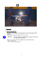
USER’S MANUAL
FLOOR CUTTER
FS 27-E / 7.5 kW
This manual should be made available to your service personnel at all times
to ensure correct and careful handling of the machine.
Maschinenbau u. Diamantwerkzeuge GmbH
Lanzstraße 4 - D-88410 Bad Wurzach
Phone +49 (0) 75 64/3 07-0 - Fax +49 (0) 75 64/3 07-5 00
[email protected] - www.lissmac.com
Edition: 2007/02
1
Introduction
This operating manual should make it easier to learn about the machine and its
features.
The operating manual contains important information on operating the machine safely,
correctly and efficiently. Following the instructions helps prevent accidents,
unnecessary repair costs and down time, which extends the machine’s reliability and
service life.
The operating manual is yet to be supplemented with instructions pertaining to national
laws concerning accident prevention and environmental protection.
The operating manual must always be accessible on the machine.
Every person working on this machine must read and follow the instructions in the
operating manual. This includes the following areas:
• Operation, including setting-up, troubleshooting, disposal of waste products, product
care, disposal of lubrication and auxiliary products.
• Servicing (maintenance, inspection, repair) and/or
• Transport
In addition to the operating manual and to complying with all national and local
regulations concerning accident prevention, the general technical regulations for safe
and correct operation must also be adhered to.
Table of Contents
1. General Safety Precautions
2. Description of Machine
3. Commissioning
4. Transport
5. Operation
6. Switching off
7. Maintenance
8. Trouble Shooting
10. Guarantee
11. Disposal
2
1. General Safety Precautions
1.1 Warning Labels and Symbols used in this Manual
Danger!
Not following the instructions can result in serious injuries or even
death.
Caution! Not following the instructions can, under certain conditions, result in
injuries.
Note!
Not following the instructions can result in damage to the machine or
other equipment.
1.2 General Safe Operating Procedures
Danger!
1.2.1 The machine has been manufactured in keeping with the most recent
technology and the recognised safety rules. Nevertheless there may be some
risk of a hazard to life and limb of the user or third persons or impairments of
the machine and other real assets respectively.
1.2.2 Use the machine only in good working condition and follow all procedures
concerning correct and safe operation, as outlined in the manual! This applies
specifically to malfunctions that can jeopardise safety!
1.2.3 This floor cutter is intended for cutting concrete or asphalt exclusively.
The cutting of wood, plastic material or metal (except concrete
reinforcements) is not permitted!
Any other utilisation of this floor cutter is considered inadmissible.
The manufacturer/supplier is not liable for any damage caused by undue
application.
Correct operation also requires following instructions in the operating
manual as well as inspection and maintenance procedures.
1.3 Organisational Measures
1.3.1 Always keep the operating manual close to the machine and easily accessible!
1.3.2 Follow all laws and regulations concerning accident prevention and
environmental
compliance listed in the supplement to this operating manual. These regulations
can, for example, apply to the use of dangerous chemicals, personal protective
equipment, and traffic laws.
3
1.3.3 Any personnel working on the machine must read this operating manual
especially this chapter on safety precautions-prior to beginning. Learning on
the job is too late. This especially applies to personnel who occasionally work
on the machine (e.g. setup and maintenance crews).
1.3.4 Perform regular spot checks to ensure that personnel are doing their jobs in a
safe and conscientious manner and that they are adhering to the instructions in
the operating manual!
1.3.5 Use personal protective equipment whenever necessary or when required by
regulations!
1.3.6 Pay attention to all safety and danger warning labels located on the machine!
1.3.7 Keep all safety and danger warning labels in/on the machine completely
legible!
1.3.8 Stop the machine and notify the parties in charge when performing safetyrelated changes on the machine or its operation!
1.3.9 Make no alterations and do not add componentry or rebuild the machine
without permission from the manufacturer!
1.3.10 Use only original spare parts!
1.3.11 Perform all scheduled inspections as needed, or use the scheduled intervals
outlined in the operating manual!
1.3.12 For carrying out maintenance work, adequate workshop equipment is
indispensable.
1.4 Qualifications for Selecting Operators; Fundamental Responsibilities
1.4.1 Only personnel of proven reliability is allowed to operate the machine.
Observe legal minimum age requirements!
1.4.2 Use only qualified and trained personnel. Clearly define staff responsibilities
concerning operation of machine, setup, maintenance, and repair works!
1.4.3 Ensure that the floor cutter is handled only by persons instructed to do so.
1.4.4 Define machine operator's responsibility - also in respect to road traffic
regulations - and his ability to object to instructions not in compliance with the
safety regulations!
4
1.4.5 Apprentices, new employees, or personnel being trained must be
accompanied at all times by an experienced operator while working
on the machine!
1.4.6 Any work at the electrical equipment of the floor cutter must be carried out by
a qualified electrician only or a trained person under the supervision of a
qualified electrician, in accordance with the rules and standards for
electronics.
1.5.1 Normal Operation
1.5.1.1 Do not perform procedures that may present a safety risk!
1.5.1.2 Take steps to ensure the machine is used only when it is
in a safe, operational state!
1.5.1.3 Machine must be examined for externally visible damage at least once per
shift! Report any changes (including performance) to the appropriate
personnel at once! If necessary, immediately stop and secure the machine!
1.5.1.4 Immediately stop and secure the machine when malfunctioning!
Promptly fix the problem!
1.5.1.5 Prior to starting work, familiarise yourself with the locality and its
environment. The environment may include obstacles within the working and
traffic area, safe floor load, necessary protection of the site towards public
traffic areas, first aid in the case of an accident.
1.5.2 Using the Machine for Extracurricular Jobs and Maintenance Procedures, e.g.
Troubleshooting; Waste Disposal
1.5.2.1 Follow the instructions in the operating manual when adjusting,
maintaining and inspecting componentry and performing scheduled
work. This includes the replacement of parts! Only qualified
personnel are allowed to perform these activities.
1.5.2.2 Notify operators of any maintenance or additional work prior to
performing it! Appoint a supervisor!
5
1.5.2.3 When the machine is completely turned off for maintenance or repair
work, it must be safeguarded against an unexpected restart.
1.5.2.4
Before cleaning machine with water or with other cleansing agents cover
and seal all openings into which, due to safety or functional reasons,
water/cleansing agent may not penetrate. Particularly protect endangered
electric motors and switches.
Do not clean the machine by a high pressure steam jet!
1.5.2.5 Completely remove all covers/tape after cleaning!
1.5.2.6 Tighten any loose screws after performing maintenance or repair work!
1.5.2.7 If the protective devices on the machine need to be removed for setting up,
maintenance or repairs, they must be reassembled immediately afterwards
and tested for their safety features in order to ensure safe operation!
1.5.2.8 Dispose of lubrication and auxiliary devices as well as spare parts in a safe
and environmentally friendly manner!
1.5.2.9 The machine must be operated on circuits with safety switch (FI) only.
1.6 Precautions for Special Types of Danger
1.6.1 Electrical Power
1.6.1.1 Only use original fuses with the electrical current for which they were
designed! Immediately turn off the machine when encountering electrical
problems!
1.6.1.2 Any work on electrical equipment must be performed by a qualified
electrician only or by trained persons under the supervision by a qualified
electrician, in compliance with the regulations for electrical engineering.
1.6.1.3 Regularly inspect/check the machine’s electrical condition. Problems, such
as loose connections (e.g. damaged cables) must be immediately repaired.
6
1.6.2 Dust
1.6.2.1 Observe all national regulations and standards when working in small
spaces!
1.6.3 Noise
1.6.3.1 Officially prescribed personal ear protection!
1.7 Transport
1.7.1
Ensure that your hoisting gear and load suspension devices have adequate
carrying capacity.
1.7.2
Have an experienced coordinator direct the lifting process!
1.7.3
Lift the machines using only approved lifting equipment as per the
instructions in the operating manual (striking points for loading procedures)!
1.7.4
Use only a vehicle providing sufficient lift capacity for transporting the
machine!
1.7.5
Secure the load. Use the appropriate striking points!
1.7.6
Turn off the power even when moving the machine only a small distance!
Before restarting, ensure the machine is securely connected!
1.7.7
Always follow the instructions in the operating manual when restarting!
7
2. Description of Machine Componentry
2.1 Component Overview
Pos. 1
Cut depth adjustment
Pos. 2
Locking for cut depth adjustment
Pos. 3
Steering rod
Pos. 4
Fixing of saw hood
Pos. 5
Saw hood
Pos. 6
Main switch
Pos. 7
Star-delta-switch
Pos. 8
Motor attachment
Pos. 9
Motor attachment
Pos. 10
Water supply
Pos. 11
Connector plug
Pos. 12
Machine frame
Pos. 13
Positioning rod
Pos. 14
Scale for cut depth adjustment
Pos. 15
Motor connector plug
2.2 Protection devices
Pos. 6
Saw blade protection cap
Emergency off switch
8
1
2
3
4
7
8
14
5
6
9
8
10
11
13
15
12
9
2.3. Technical data
FS 27- E / 7.5 kW
Cut depth
320 mm (12.6“)
Saw blade diameter
800 mm (31.5“)
Saw blade holder (bore hole)
25.4 mm (1“)
Dimensions L/W/H
1100/600/980 mm (43“/24“/39“)
Weight
155 kg (341 lbs.)
Left-/Right Cutting
yes
Motor output
7.5 kW
Voltage/Frequency
400 V / 50 Hz
Current consumption
16.1 A
Number of revolutions – saw blade
1350 r.p.m.
2.4. Noise emitted FS 27-E
Guaranteed sound level
= 96 dB(A)
Attention!
Ear muffs must be worn if a 90 dB(A) noise level is
exceeded!
2.5. Vibration of the handle
Total vibration value
Operating state
Idle running
Saw blade diameter 600m
ahv = 1,4 m/s
-2
By the measurements following guidelines were considered:
EN ISO 5349, VD, 2057 Page 2, Guideline 2002/44/EEC
During the cutting process the mentioned value can be up to 1.7-fold higher. This
depends on operational conditions, machine condition, handling and the used
diamond blades.
10
3. Commissioning
Prior to starting work, familiarize yourself with the operation of the floor cutter.
3.1 Start preparation
- On demand install saw blade (see 5.2 and 5.3)
- Drive floor cutter in position
3.2 Check sense of rotation of saw blade
-
Switch the main switch (Pos. 6) on
Shortly switch star-delta-switch (Pos. 7) to „star“
Check sense of rotation of saw blade
Ensure arrow on the saw blade cover
3.3 Change sense of rotation
-
Switch main switch (Pos. 6) off
Remove feeding cable from plug (Pos. 11)
Turn phases of plug (Pos. 11) with screw driver
Push white disc inwards and turn it
3.4 Trial run
-
Turn main switch (Pos. 6)
Put switch (Pos. 7) to „Star“
Wait until motor obtains an even number of revolutions (constant noise)
Put switch (Pos. 7) to „delta“
ATTENTION! Observe that there is always sufficient cooling water provided at
the saw blade?
Place positioning rod and saw blade above cutting joint
- Mount water hose on coupling (Pos. 10) and open the water cock
- Slowly start movement downwards by crank (Pos. 1) – until saw blade begins
to cut
- Put cut depth indicator (Pos. 14) to „Zero“
- Dip saw blade in until desired cut depth (indicator Pos. 14)
Turn crank (Pos. 1)
- Slowly start forward movement
Caution!
- Dry cuts are not allowed!
- To less cooling water lead to premature wear or to a defect of the saw
blade
11
4. Transport
4.1 To transport:
- positioning rod folded up
- lift saw arm up for sufficient ground clearance
- arrest spindle and bolt (Pos. 2)
4.2 Displacement by crane
- Observe all points specified under 4.1
Put crane suspension gear into eye hook (Pos. 8)
∗ Observe weight of machine
- Carefully lift and put down the machine
4.3 Dismantle floor cutter in 3 parts
- Detach wing screw (Pos. 4)
- Remove saw hood (Pos. 5) with rod assembly
- Open plug (Pos. 15)
- Disconnect water hose
- Turn motor totally down via crank handle (Pos. 1)
- Remove ring bolts (Pos. 8)
- Draw-out the steering rods (Pos. 3)
- Remove cotter pin and hexagon nut (Pos. 9)
- Turn motor receiver upwards by crank handle (Pos. 1)
- Fix both steering rods at the motor (Pos. 3) with ring bolts (Pos. 8)
- The motor can be transported by two persons
- Assembly in reverse order
12
8
5. Operation
5.1 Normal cutting operation
Attention: The machine must be operated on circuits with safety switch
(FI) only.
- Adapt forward speed to cut depth and cutting material.
CAUTION!
The floor cutter has the tendency to „climb“ in the front, if
the forward feed is to high.
- Make sure that the saw blade is supplied with sufficient cooling water.
(Point 7 Maintenance)
∗ Only use fresh and clean water!
13
5.2 Change of saw blade
- Set the saw blade into the height
- Switch floor cutter completely off
- Pin up feed line
- Detach wing screw (Pos. 4)
- Draw saw hood holder out of C-rail
- Lift saw hood upwards
- Open flange nut (right-hand thread)
- Pull saw flange - pressure disc and saw blade off
- Clean surface of flange thoroughly.
- Install new saw blade
ATTENTION! ∗Arrows indicating the sense of rotation on saw blade and
on protection cap must coincide
∗ Observe that the tappet of the flange fits into tappet hole
provided in saw blade
- Reinstall flange pressure disc and flange nut
ATTENTION! Mount the cotter pin!
- Mount saw hood
5.3 Choice of saw blade
Type
NAS
NAK
NBA
NBF
Work
Asphalt with oblique protection segment
Asphalt with core protection segment
Concrete
Fresh concrete
14
5.4 Change from right- to left-cut
- Detach wing screw (Pos. 4)
- Remove saw hood (Pos. 5) with rod assembly
- Open plug (Pos. 15)
- Disconnect water hose
- Turn motor totally down via crank handle (Pos. 1)
- Remove ring bolts (Pos. 8)
- Turn motor receiver approx. 8-10 cm upwards by crank handle (Pos. 1)
- now you could tilt the motor by 180°
- Turn motor receiver again downwards (Pos. 1)
ATTENTION!
Adapt screws and pins
- Mount ring bolt (Pos. 8)
- Mount water hose attachement (Pos. 10) on the other side
Attention! Turn saw blade (see also 5.2)
- Close plug (Pos. 15)
- Mount saw hood (Pos. 5) (displace rod assembly)
- Start saw blade direction by changing the poles of the plugs (Pos. 11)
(see also 3.3)
ATTENTION! Left-hand cutting is the regular working order of the floor
cutter, right-hand cuts should be used for short courses only!
15
1
2
3
4
7
8
14
5
6
9
8
10
11
13
15
12
16
6. Switching off
- Turn switch (Pos. 7) back
- Put main switch (Pos. 6) to „Zero“
- Remove feed line
- Crank saw hood upwards until brakes press the wheel
7. Maintenance
daily
Check v-belt saw blade
drive (see 8.2)
Check screws (Pos. 8)
(screwed-down?)
Lubricate spindle of cut
depth adjustment (Pos. 1)
with spray grease
weekly
monthly
half-yearly
X
X
X
Tighten all screws after approx. 20 working hours!
Restretch V-belts after approx. 2 working hours!
8. Trouble shooting
8.1
Defect
Possible cause
Remedial action
poor cutting performance
saw blade does not move
slack v-belt
restretch, exchange (see 8.3)
no water at saw blade
clogged supply line
dirty sieve
clean sieve inside supply line
flush water supply line (5-8 bar)
8.2 Checking of V-belt tension
- Remove safety cap (Pos. 16)
- At medium expenditure of force, V-belt should yield by one width of belt when
pressed down.
8.3 Adjusting the V-belt tension (Pos. 16)
- Open hexagon nut (Pos. 17)
- Adjust screw (Pos. 18) as required
- Tighten hexagon nut (Pos. 17)
- The V-belt can be restretched again on the opposite side.
17
8.4 Adjustment of the motor protection switch
The motor protection switch in the switch box ensures the securing of the emergency
off switch and the disengaging of the thermo sensing device. It is adjusted to 14 A.
Securing of the motor is made by the thermo sensing device.
16
18
17
18
10. Guarantee
The guarantee time is 12 months. The following wearing parts you will get only
in guarantee, when the wearing is not due to working conditions.
Wearing parts are parts, which will be worn out in working conditions due to intended
use of a machine. The time of wearing is not defineable in an uniform way, it
depends on their application intensity. The wearing parts for each specific machine
has to be attended, adjusted and if necessary exchanged in accordance to the user’s
manual of the producer.
For wearing due to working conditions there is no guarantee.
•
•
•
•
•
•
•
•
•
•
•
•
•
•
•
•
•
•
•
•
•
•
•
•
•
•
•
•
•
Advance- and driving elements as toothed racks, toothed wheels, pinions,
spindles, spindle nuts, spindle bearings, ropes, chains, chain wheels, belts
Washers, cables, hoses, collars, plugs, clutches and switches for pneumatic,
hydraulic, water, elektricity, fuel
guidance elements as guiding joints, guiding bushes, guiding rails, rolls, bearing,
antislipping devices
flushing head seal
sliding- and rolling bearing, which are not running in an oil-bath
rotary shaft seal and sealing elements
friction- and overload clutches, brake gears
graphite brush, collectors
potentiometer control and manual control elements
fuses and lamps
process materials
fixing materials as plugs, anchor and screws
bowden wires
lamellars
membranes
spark plugs, glow plugs
parts of reversing starter as start by rope, start by handle, start by roll, start by
spring
sealing brush, packing rubber, splash guard rags
filter all types
driving-, deflection roller and roller lining
protection elements for rope lays
running- and driving wheels
water pumps
transport roller for cutting material
drilling-, parting-off- and cutting tools
conveyor belt
rubber stripes
needled felt protection
energy accumulation
19
11. Disposal
This machine is in subject to directive no. 2002/96EG (WEEE) dated 27.01.2003.
The manufacturer is engaged to take back this machine for the disposal. The
machine has to be delivered to the manufacturer or to the named point of
acceptance exempt from charges.
20
LISSMAC Maschinenbau u. Diamantwerkzeuge GmbH
EC Declaration of conformity for
Floor cutter
FS 27-E
Producer
LISSMAC Maschinenbau u. Diamantwerkzeuge GmbH
Lanzstraße 4
D-88410 Bad Wurzach
Storage of the technical Anton Hess (Assistent der technischen Leitung)
documents by:
LISSMAC Maschinenbau und
Diamantwerkzeuge GmbH
Lanzstr. 4
D-88410 Bad Wurzach
Description of
machine
Floor cutter: FS 27-E
Floor cutter with electric motor 7.5 kW
Cut depth: 320 mm
Applied procedure of
conformity evaluation:
Internal control of production
(RL 2000/14/EG Annex V)
Measured sound level:
95 dB
Guaranteed sound level: 96 dB
Relevant EC-directives EC Machine Directive (Council Directive 98/37/EEC)
Noise Directive 2000/14/EEC
EC Directive 2002/95/EG (RoHS)
EC Directive 2002/ 96/ EG (WEEE)
EC Low Voltage Directive (Council Directive 73/23 EEC)
changed by 93/68/EEC,
EC Electromagnetic Compatibility Directive 89/336/EEC,
changed by 98/68/EEC,
EN 12100, 13862, EN 60204-1, EN 294, EN ISO 3744
Authorized person
legally responsible:
LISSMAC
Maschinenbau und Diamantwerkzeuge GmbH
Gewerbepark West – Lanstrasse 4
88410 Bad Wurzach
Tel.: (0 75 64) 3 07-0, Fax: (0 75 64) 3 07-5 00
Mail: [email protected] – www.lissmac.com
....................................................
ppa. Josef Weiland
(Technical Director)
21