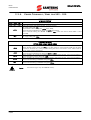
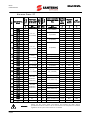
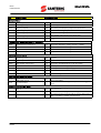
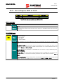
1
• 15V0102B1 •
SINUS PENTA
MULTIFUNCTION AC DRIVE
BASIC
USER MANUAL
Issued on 03/07/08
R. 02
SW Ver.1.66x
English
• This manual is integrant and essential to the product. Carefully read the instructions contained herein as they
provide important hints for use and maintenance safety.
• This device is to be used only for the purposes it has been designed to. Other uses should be considered improper
and dangerous. The manufacturer is not responsible for possible damages caused by improper, erroneous and
irrational uses.
• Elettronica Santerno is responsible for the device in its original setting.
• Any changes to the structure or operating cycle of the device must be performed or authorized by the Engineering
Department of Elettronica Santerno.
• Elettronica Santerno assumes no responsibility for the consequences resulting by the use of non-original spareparts.
• Elettronica Santerno reserves the right to make any technical changes to this manual and to the device without prior
notice. If printing errors or similar are detected, the corrections will be included in the new releases of the manual.
• Elettronica Santerno is responsible for the information contained in the original version of the Italian manual.
• The information contained herein is the property of Elettronica Santerno and cannot be reproduced. Elettronica
Santerno enforces its rights on the drawings and catalogues according to the law.
Elettronica Santerno S.p.A.
Strada Statale Selice, 47 - 40026 Imola (BO) Italy
Tel. +39 0542 489711 - Fax +39 0542 489722
www.elettronicasanterno.com [email protected]
SINUS PENTA
BASIC
USER MANUAL
0.
STARTUP
NOTE
This manual covers basic installations of the Penta drive. For more details, please refer
to the standard Sinus Penta’s Installation Instructions manual.
NOTE
SINUS PENTA drives are factory set with the IFD control algorithm (V/f) allowing
performing the first startup of the equipment. The default functions are given in this
section, particularly in step 5) Start up.
1) Inspection:
Check if the size of the Penta drive is greater than or equal to the size of the connected motor
according to the drive nameplate. See the Inspection upon Receipt of the Goods section in this manual.
2) Installation
and wiring:
The IP rating of the Penta drive is given in the Installing the Equipment section in this manual. Ensure
that sufficient ventilation is provided to the drive. More details are given in the standard Sinus Penta’s
Installation Instructions manual.
3) Power on:
Power on the drive; check if the keypad turns on.
4) Parameter
setting:
For an easier startup of the Penta drive, you can activate the Start-Up Menu. The Start-Up Menu is a
wizard allowing programming the main parameters for the connected motor.
The Start-Up Menu is displayed when the Penta drive is first started. The Start-Up Menu can be
reactivated at any time. To do so, set P265 in “Start Up” mode:
[ I D P ] S I NU S
P ENT A
S T A R T - UP
MENU
P r e s s
ENT E R
t o
s t a r t
Press Enter to enter the wizard.
Before entering the control parameters, you are asked to choose a dialogue language:
P 2 6 3
L a n g u a g e
→@@@@@@@@@@@@@@@
Then you are asked to choose the display mode of the Start Up Menu:
Whe n
d o e s
t he
S t a r t - U p M e n u
a c t i v a t e ?
→@@@@@@@@@@@@@@@
Choose one of the following:
1
2
3
4
2/65
:
:
:
:
EV E
ON L
N EX
N E V
R Y
S T A R T - U P
Y N OW
T
S T A R T - U P
E R
SINUS PENTA
BASIC
USER MANUAL
If you select “EVERY START–UP”, the wizard appears whenever the Penta drive is powered on;
if you select “ONLY NOW”, you can scroll through the menu and the wizard is disabled as soon as you
quit the menu;
if you select “NEXT START–UP”, the menu is displayed only when the Penta drive is next started up;
if you select “NEVER”, the Start-Up menu is disabled.
Parameters included in the Start-Up menu:
Parameter
C008
Description
Rated mains voltage
Visibility
C010
Type of control algorithm
C012
Speed feedback from encoder
[only if FOC is active]
C013
Type of V/f pattern
[only if IFD is active]
C015
Rated motor power
C016
Rated motor rpm
C017
Rated motor power
C018
Rated motor current
C019
Rated motor voltage
C021
No-load current of the motor
C028
Min. motor speed
C029
Max. motor speed
C034
Voltage preboost
P009
Acceleration ramp time
[only if FOC is active]
[only if IFD is active]
P010
Deceleration ramp time
C043
Current limit while accelerating
[only if IFD is active]
C044
Current limit at constant rpm
[only if IFD is active]
C045
Current limit while decelerating
[only if IFD is active]
C048
Torque limit
[only if VTC/FOC are active]
C189
Encoder operating mode
[only if FOC is active]
C190
Encoder A pls/rev
[only if FOC is active]
C191
Encoder B pls/rev
[only if FOC is active]
I073
Autotuning selection
[only if VTC/FOC are active]
I074
Motor tuning selection
[only if VTC/FOC are active]
C265
Motor thermal protection
C267
Motor thermal time constant
[only if protection is active]
C291
PID operating mode
C285
PID reference selection
[only if PID is active]
C288
PID feedback selection
[only if PID is active]
P267
Preset PID units of measure
[only if PID is active]
P257
PID measure scale factor
[only if PID is active]
P236
Max. value of PID output
[only if PID is active]
P237
Min. value of PID output
[only if PID is active]
P237a
PID wake up enable
[only if PID is active]
P237b
PID wake up level
[only if PID is active]
3/65
SINUS PENTA
BASIC
USER MANUAL
After setting the last parameter and moving the cursor forward, the following page will appear:
P r e s s
U P
A R R OW
t o
qu i t
D OWN A R R OW
t o
c o n t i n u e
Terminal Control:
i)
Activate the ENABLE input (terminal 15).
ii) Activate the START input (terminal 14).
iii) Send speed reference to REF: 0-10V (terminals 1,
2 & 3)
REFERENCE
INPUT
0 -: 10 V
2 ÷ 10kohm
or
Send speed reference to AIN1: 4-20mA (terminals
5 & 6). This requires Source Selection input on
MDI6 to be active (terminal 19).
4 ÷ 20 mA
ANALOG
INPUT
4 -: 20 mA
The RUN LED and REF LED will be lit and the motor
will start. Make sure that the motor is rotating in the
correct direction.
5) Startup:
If not, operate on terminal MDI5 (terminal 18)
(CW/CCW) or open the ENABLE and START terminals.
Shut off the drive, wait at least 5 minutes and reverse
two of the motor phases.
Keypad Control:
i)
Activate the ENABLE input (terminal 15).
ii) Press the LOCAL/REMOTE button on the keypad.
iii) The L-CMD and L-REF LEDs will be lit.
START (MDI1)
ENABLE (MDI2)
RESET (P/B) (MDI3)
MULTISPEED 0 (MDI4)
MULTISPEED 1 (MDI5)
SOURCE SELECTION (MDI6)
LOCAL / REMOTE (P/B) (MDI7)
Cw / CCW (MDI8)
iv) Press the START button.
v) Hold the Up button to increase the speed
reference.
The RUN LED and REF LED will come on and the
motor will start. Make sure that the motor is rotating in
the correct direction.
If not, press the FWD/REV button or press STOP. Shut off the drive, wait at least 5 minutes and
reverse two of the motor phases.
6) Possible
failures:
7) Additional
parameter
alterations:
8) Reset:
4/65
If no failure occurred, go to the next step. Otherwise, check the drive connections paying particular
attention to supply voltages, DC link and input reference.
Also check if alarm messages are displayed. In the MEASURES MENU, check values in the Fault List for
the reference speed (M000), the supply voltage to the drive (M030), the DC link voltage (M029), and
the condition of control terminals (M033). Check to see if these readouts match with the measured
values.
In BASIC user level, adjustments can be made to a limited number of parameters. The SINUS PENTA
has a wide range of functions; to access these function, set the user level to ADVANCED or
ENGINEERING by adjusting parameter P001 accordingly.
You can write down any custom parameters in the table given on the last page of this manual
(CUSTOM PARAMETERS).
If an alarm trips, find the cause responsible for the alarm and reset the equipment. Enable MDI3
(terminal 16) or press the RESET key on the display/keypad.
SINUS PENTA
1.
BASIC
USER MANUAL
TABLE OF CONTENTS
1.1.
Chapters
0.
1.
STARTUP .................................................................................................................................................... 2
TABLE OF CONTENTS ................................................................................................................................ 5
1.1.
Chapters ................................................................................................................................................... 5
1.2.
Figures ...................................................................................................................................................... 6
1.3.
Tables ....................................................................................................................................................... 6
1.4.
How to use this Manual .............................................................................................................................. 7
1.4.1. Overview .............................................................................................................................................. 7
2.
HARDWARE DESCRIPTION AND INSTALLATION........................................................................................ 8
2.1.
Caution Statements .................................................................................................................................... 8
2.2.
Inspection upon Receipt of the Goods ....................................................................................................... 10
2.2.1. Nameplate.......................................................................................................................................... 10
2.3.
Installing the Equipment ........................................................................................................................... 11
2.3.1. Environmental Requirements for the Equipment Installation, Storage and Transport ................................ 11
2.3.2. Size, Weight and Dissipated Power – 2T Class....................................................................................... 12
2.3.3. Size, Weight and Dissipated Power – 4T Class....................................................................................... 13
2.3.4. Power Terminals / Bars for S05 – S50................................................................................................... 14
2.3.5. Connecting Bars in S60 ....................................................................................................................... 16
2.3.6. Cross-sections of the Power Cables and Sizes of the Safety Devices ........................................................ 17
3.
USING THE DISPLAY/KEYPAD .................................................................................................................. 21
3.1.
Overview ................................................................................................................................................. 21
3.2.
Menu Tree ............................................................................................................................................... 21
3.3.
Navigation............................................................................................................................................... 22
3.4.
Function Keys........................................................................................................................................... 23
3.5.
Indicator LEDs in the Display/Keypad ........................................................................................................ 24
4.
WIRING.................................................................................................................................................... 25
4.1.
Wiring Diagram....................................................................................................................................... 25
5.
MEASURES MENU .................................................................................................................................... 26
5.1.
Overview ................................................................................................................................................. 26
5.2.
Fault List Menu/Power Off List Menu ......................................................................................................... 29
6.
PRODUCT MENU...................................................................................................................................... 30
6.1.
Overview ................................................................................................................................................. 30
6.2.
Parameter P263 and Fire Mode Enable Password ...................................................................................... 30
7.
PASSWORD AND USER LEVEL MENU ....................................................................................................... 32
7.1.
Overview ................................................................................................................................................. 32
7.2.
List of Parameters P000 and P001 ............................................................................................................ 32
8.
RAMPS MENU .......................................................................................................................................... 33
8.1.
Overview ................................................................................................................................................. 33
8.2.
List of Parameters P009 and P010 ............................................................................................................ 33
9.
MULTISPEED MENU.................................................................................................................................. 34
9.1.
Overview ................................................................................................................................................. 34
9.2.
List of Parameters P080 to P085 ............................................................................................................... 34
10.
SPEED LOOP AND CURRENT BALANCING MENU (VTC & FOC ONLY) ................................................. 35
10.1.
Overview ................................................................................................................................................. 35
10.2.
List of Parameters P125 to P131 ............................................................................................................... 35
11.
AUTOTUNE MENU............................................................................................................................... 37
11.1.
Overview ................................................................................................................................................. 37
11.1.1.
Motor Autotune and Adjusting Loops ............................................................................................... 38
11.1.2.
Checking the Encoder Operation..................................................................................................... 39
11.2.
List of Inputs I073 and I074...................................................................................................................... 40
12.
MOTOR CONTROL MENU.................................................................................................................... 41
12.1.
Overview ................................................................................................................................................. 41
12.1.1.
Electrical Specifications of the Connected Motor ............................................................................... 41
12.1.2.
V/F Pattern (IFD Only) ..................................................................................................................... 42
12.2.
List of Parameters C008 to C034 .............................................................................................................. 43
13.
LIMITS MENU....................................................................................................................................... 47
13.1.
Overview ................................................................................................................................................. 47
13.2.
List of Parameters C043 to C045 .............................................................................................................. 47
14.
ENCODER/FREQUENCY INPUTS MENU ............................................................................................... 49
5/65
SINUS PENTA
BASIC
USER MANUAL
14.1.
Overview ................................................................................................................................................. 49
14.1.1.
When ES836 is NOT Used .............................................................................................................. 49
14.2.
List of Parameters C189 to C191 .............................................................................................................. 50
15.
MOTOR THERMAL PROTECTION MENU ............................................................................................... 52
15.1.
Overview ................................................................................................................................................. 52
15.2.
List of Parameters C265 and C267 ........................................................................................................... 53
16.
EEPROM MENU.................................................................................................................................... 54
16.1.
Overview ................................................................................................................................................. 54
16.2.
List of Inputs I009 to I012......................................................................................................................... 55
17.
ALARMS AND WARNINGS ................................................................................................................... 56
17.1.
What Happens when a Protection Trips ..................................................................................................... 56
17.2.
What To Do when an Alarm Trips ............................................................................................................. 57
17.3.
Alarm Code List ....................................................................................................................................... 58
17.4.
Warnings................................................................................................................................................. 62
17.5.
State List .................................................................................................................................................. 64
18.
CUSTOM PARAMETERS ........................................................................................................................ 65
1.2.
Figures
Figure 1: Nameplate of the Penta Drive....................................................................................................................... 10
Figure 2: Connecting bars in S60................................................................................................................................ 16
Figure 3: Menu Tree................................................................................................................................................... 21
Figure 4: Navigation example..................................................................................................................................... 22
Figure 5: Wiring Diagram........................................................................................................................................... 25
Figure 6: Types of programmable V/f patterns............................................................................................................. 42
Figure 7: Trip current drop depending on speed values................................................................................................ 52
1.3.
Tables
Table 1: Parameter P263 and Fire Mode enable Password. .......................................................................................... 30
Table 2: List of parameters P000 and P001.................................................................................................................. 32
Table 3: List of parameters P009 and P010. ................................................................................................................ 33
Table 4: List of parameters P080 to P085. ................................................................................................................... 34
Table 5: List of parameters P125 to P131. ................................................................................................................... 35
Table 6: Programmable “Motor Tune” functions. ......................................................................................................... 38
Table 7: List of Inputs I073 and I074........................................................................................................................... 40
Table 8: List of parameters C008 to C034................................................................................................................... 43
Table 9: List of parameters C043 to C045................................................................................................................... 47
Table 10: List of parameters C189 to C191................................................................................................................. 50
Table 11: Codification of C189. ................................................................................................................................. 50
Table 12: List of parameters C265 and C267.............................................................................................................. 53
Table 13: List of programmable inputs I009 to I012. ................................................................................................... 55
Table 14: Alarm Code List. ......................................................................................................................................... 61
Table 15: Warning list. ............................................................................................................................................... 63
Table 16: State List. .................................................................................................................................................... 64
6/65
SINUS PENTA
1.4.
BASIC
USER MANUAL
How to use this Manual
1.4.1.
O VERVIEW
This User Manual (Basic User Manual) provides information required to setup and monitor the drives of the Sinus Penta
series manufactured by Elettronica Santerno SpA when used in the basic mode.
The section concerning the hardware description and installation covers basic wiring only. Refer to the standard Installation
Instructions manual to install additional options and/or to configure analog/digital inputs and outputs.
The Sinus Penta is delivered in Basic mode, which provides a cut down parameter set and preset I/O settings. If additional
adjustment is required, this may be achieved by setting the drive to Advanced or Engineering using parameter P001 (see
the PASSWORD AND USER LEVEL MENU). In this case, please refer to the standard Programming Instructions manual.
Setup/monitoring may be obtained using one or both of the following options:
1)
Display/keypad unit;
2)
Serial link through RS485 standard port or ES822 optional board.
For the instructions on how to use and remote the display/keypad unit, please refer to the standard Installation Instructions
manual.
Any information sent to/from the drive through the display/keypad unit may be obtained
also via serial link using the RemoteDrive software application provided by Elettronica
Santerno.
The RemoteDrive allows the following functions: image acquisition, keypad simulation,
oscilloscope functions and multifunction tester, table compiler including operation data log,
parameter setup and data reception-transmission-storage from and to a calculator, scan
function for the automatic detection of the connected drives (up to 247 drives may be
connected).
When used in Advanced or Engineering mode, many additional functions are available. These include the following:
•
•
•
•
•
•
•
•
•
•
•
•
•
•
•
•
•
•
•
•
•
•
•
•
Customisation of Keypad navigation.
Customisation of standard monitoring values.
Selection of up to 4 acceleration and deceleration ramps.
Customisation and scaling of analog input signals.
Selection of up to 15 preset speeds.
Configuration of 3 prohibit speeds.
Utilisation of a speed variation function.
Tuning of VTC and FOC algorithms.
Customisation of analog output signals.
Allocation of internal timer functions to digital I/O.
PID activation and tuning.
Configuration of Digital output comparator and logic functions.
Master/slave operation with torque control.
Adjustment of current and torque limits.
Customisation of digital inputs.
Setting of control source for start and speed commands.
Configuration of a connected encoder.
DC braking.
Dynamic braking.
Speed Search function.
Autoreset.
Motor thermal modelling and thermistor allocation.
Crane control functions.
Serial and Fieldbus communication.
If any of the above functions is required, use parameter P001 to access the Advanced or Engineering settings.
7/65
SINUS PENTA
BASIC
USER MANUAL
2.
HARDWARE DESCRIPTION AND INSTALLATION
2.1.
Caution Statements
SYMBOLS:
DANGER
Indicates operating procedures that, if not correctly performed, may cause serious injury or
death due to electrical shock.
CAUTION
Indicates operating procedures that, if not carried out, may cause serious equipment
failure.
NOTE
Indicates important hints concerning the equipment operation.
SAFETY STATEMENTS TO FOLLOW WHEN INSTALLING AND OPERATING THE EQUIPMENT:
NOTE
1.
2.
Always read this instruction manual before starting the equipment.
The ground connection of the motor casing should follow a separate path to avoid
possible interferences.
1.
ALWAYS PROVIDE PROPER GROUNDING OF THE MOTOR CASING AND THE DRIVE
FRAME.
The drive may generate an output frequency up to 1000 Hz; this may cause a motor
rotation speed up to 20 (twenty) times the motor rated speed: never use the motor at
higher speed than the max. allowable speed stated on the motor nameplate.
ELECTRICAL SHOCK HAZARD – Never touch the drive electrical parts when the drive
is on; always wait at least 5 minutes after switching off the drive before operating on
the drive.
Never perform any operation on the motor when the drive is on.
Do not perform electrical connections on the motor or the drive if the drive is on.
Electrical shock hazard exists on output terminals (U,V,W) and resistive braking
module terminals (+, –, B) even when the drive is disabled. Wait at least 5 minutes
after switching off the drive before operating on the electrical connection of the motor
or the drive.
MECHANICAL MOTION – The drive determines mechanical motion. It is the
operator's responsibility to ensure that this does not give rise to any dangerous
situation.
EXPLOSION AND FIRE – Explosion and fire hazard exists if the equipment is installed
in presence of flammable fumes. Do not install the drive in places exposed to
explosion and fire hazard, even if the motor is installed there.
2.
3.
DANGER
4.
5.
6.
7.
8/65
SINUS PENTA
BASIC
USER MANUAL
1.
2.
3.
4.
CAUTION
5.
Do not connect supply voltages exceeding the equipment rated voltage to avoid
damaging the internal circuits.
If the drive is installed in environments exposed to flammable and/or explosive
substances (AD zones according to IEC 64-2 standards), please refer to IEC 64-2,
EN 60079-10 and related standards.
Respect the environmental requirements for the equipment installation.
The bearing surface of the drive must be capable of withstanding high temperatures
(up to 90°C).
The drive electronic boards contain components which may be affected by
electrostatic discharges. Do not touch them unless it is strictly necessary. Always be
very careful so as to prevent any damage caused by electrostatic discharges.
9/65
SINUS PENTA
BASIC
USER MANUAL
2.2.
Inspection upon Receipt of the Goods
Make sure that the equipment is not damaged and that it complies with the equipment you ordered by referring to the
nameplate located on the drive front part. The drive nameplate is described below. If the equipment is damaged, contact
the supplier or the insurance company concerned. If the equipment does not comply with the one you ordered, please
contact the supplier as soon as possible.
If the equipment is stored before being started, make sure that the ambient conditions do not exceed the ratings mentioned
in the Installing the Equipment section. The equipment guarantee covers any manufacturing defect. The manufacturer has
no responsibility for possible damages occurred when shipping or unpacking the drive. The manufacturer is not
responsible for possible damages or faults caused by improper and irrational uses; wrong installation; improper conditions
of temperature, humidity, or the use of corrosive substances. The manufacturer is not responsible for possible faults due to
the drive operation at values exceeding the drive ratings and is not responsible for consequential and accidental damages.
The equipment is covered by a 3-year guarantee starting from the date of delivery.
Product ID:
S PENTA 0005
4
T
Size
Model
PENTA
Voltage Ratings
2 = 200-240 V
4 = 380-500 V
5 = 500-575 V
6 = 575-690 V
Product Range
S = SINUS
SB = SINUS BOX
SC = SINUS CABINET
2.2.1.
B
A2
Brake chopper
X = None
B = Built-in
Power supply
T = Three-phase
S = Single-phase
C = DC Fed
D = 12-Pulse input
N AMEPLATE
Figure 1: Nameplate of the Penta Drive.
2
Keypad
X = None
K = Built-in
EMC Filter
I = None
A1 = First env. category C2
A2 = Second env. category C3
B = First env. category C1
Typical nameplate for 4T Penta Drives:
10/65
X
IP Rating
0 = IP 00
2 = IP 20
3 = IP 24-31
4 = IP 42
5 = IP 54
C = Air Cond.
SINUS PENTA
2.3.
BASIC
USER MANUAL
Installing the Equipment
The drives of the SINUS PENTA series (degree of protection IP20) can be installed inside another enclosure. Only models
with degree of protection IP54 may be wall-mounted.
The drives must be installed vertically.
The ambient conditions, the instructions for the mechanical assembly and the electrical connections of the drives are
detailed in the sections below.
CAUTION
This manual covers basic installation for Sinus Penta drives up to size S60.
For more details, or for installation instructions as per sizes greater than S60, please refer
to the standard Sinus Penta’s Installation Instructions manual.
CAUTION
Do not install the drive horizontally or upside-down.
CAUTION
Do not mount any heat-sensitive components on top of the drive to prevent them from
damaging due to hot exhaust air.
CAUTION
The drive bottom may reach high temperatures; make sure that the drive bearing surface
is not heat-sensitive.
2.3.1.
E NVIRONMENTAL R EQUIREMENTS FOR THE E QUIPMENT
I NSTALLATION , S TORAGE AND T RANSPORT
Operating ambient temperatures
0 – 40 °C with no derating
from 40°C to 50°C with a 2% derating of the rated current for
each degree beyond 40°C
Ambient temperatures for storage and transport
– 25 °C - + 70 °C
Installation environment
Pollution degree 2 or higher.
Do not install in direct sunlight and in places exposed to
conductive dust, corrosive gases, vibrations, water sprinkling or
dripping (except for IP54 models); do not install in salty
environments.
Altitude
Up to 1000 m above sea level.
For higher altitudes, derate the output current of 1% every 100
m above 1,000 m (max. 4,000 m).
Operating ambient humidity
From 5% to 95%, from 1g/m3 to 29g/m3, non condensing and
non freezing (class 3k3 according to EN50178)
Storage ambient humidity
From 5% to 95%, from 1g/m3 to 29g/m3, non condensing and
non freezing (class 1k3 according to EN50178)
Ambient humidity during transport
Max. 95%, up to 60g/m3; condensation may appear when the
equipment is not running (class 2k3 according to EN50178)
Storage and operating atmospheric pressure
From 86 to 106 kPa
(classes 3k3 and 1k4 according to EN50178)
Atmospheric pressure during transport
From 70 to 106 kPa (class 2k3 according to EN50178).
CAUTION
As ambient conditions strongly affect the drive life, do not install the equipment in
places that do not have the above-mentioned ambient conditions.
11/65
SINUS PENTA
BASIC
USER MANUAL
2.3.2.
Size
S05
S10
S12
S15
S20
S30
S40
S50
S60
12/65
S IZE , W EIGHT
MODEL
SINUS
SINUS
SINUS
SINUS
SINUS
SINUS
SINUS
SINUS
SINUS
SINUS
SINUS
SINUS
SINUS
SINUS
SINUS
SINUS
SINUS
SINUS
SINUS
SINUS
SINUS
SINUS
SINUS
SINUS
SINUS
SINUS
SINUS
SINUS
SINUS
SINUS
SINUS
SINUS
SINUS
SINUS
SINUS
SINUS
PENTA
PENTA
PENTA
PENTA
PENTA
PENTA
PENTA
PENTA
PENTA
PENTA
PENTA
PENTA
PENTA
PENTA
PENTA
PENTA
PENTA
PENTA
PENTA
PENTA
PENTA
PENTA
PENTA
PENTA
PENTA
PENTA
PENTA
PENTA
PENTA
PENTA
PENTA
PENTA
PENTA
PENTA
PENTA
PENTA
0007
0008
0010
0013
0015
0016
0020
0016
0017
0020
0025
0030
0035
0023
0033
0037
0038
0040
0049
0060
0067
0074
0086
0113
0129
0150
0162
0179
0200
0216
0250
0312
0366
0399
0457
0524
AND
L
H
D
mm
mm
mm
170
340
175
215
391
218
215
401
225
225
466
331
279
610
332
302
748
421
630
880
381
666
1000
421
890
1310
530
D ISSIPATED P OWER – 2T C LASS
Power
Weight Dissipated at
Inom
kg
W
7
160
7
170
7
220
7
220
7
230
7
290
7
320
10.5
350
10.5
380
10.5
420
11.5
525
11.5
525
525
11.5
11
390
12
500
12
560
22.5
750
22.5
820
22.5
950
33.2
950
33.2
1250
36
1350
36
1500
51
2150
51
2300
51
2450
2700
51
112
3200
112
3650
112
4100
4250
112
148
4900
148
5600
148
6400
260
7400
260
8400
SINUS PENTA
2.3.3.
Size
S05
S10
S12
S15
S20
S30
S40
S50
S60
BASIC
USER MANUAL
S IZE , W EIGHT
MODEL
SINUS PENTA
SINUS PENTA
SINUS PENTA
SINUS PENTA
SINUS PENTA
SINUS PENTA
SINUS PENTA
SINUS PENTA
SINUS PENTA
SINUS PENTA
SINUS PENTA
SINUS PENTA
SINUS PENTA
SINUS PENTA
SINUS PENTA
SINUS PENTA
SINUS PENTA
SINUS PENTA
SINUS PENTA
SINUS PENTA
SINUS PENTA
SINUS PENTA
SINUS PENTA
SINUS PENTA
SINUS PENTA
SINUS PENTA
SINUS PENTA
SINUS PENTA
SINUS PENTA
SINUS PENTA
SINUS PENTA
SINUS PENTA
SINUS PENTA
SINUS PENTA
SINUS PENTA
SINUS PENTA
SINUS PENTA
SINUS PENTA
0005
0007
0009
0011
0014
0016
0017
0020
0025
0030
0035
0016
0017
0020
0025
0030
0034
0036
0038
0040
0049
0060
0067
0074
0086
0113
0129
0150
0162
0179
0200
0216
0250
0312
0366
0399
0457
0524
AND
L
H
D
mm
mm
mm
170
340
175
215
391
218
215
401
225
225
466
331
279
610
332
302
748
421
630
880
381
666
1000
421
890
1310
530
D ISSIPATED P OWER – 4T C LASS
Power
Weight Dissipated at
Inom
kg
W
7
215
7
240
7
315
7
315
7
315
10.5
350
10.5
380
10.5
420
11.5
525
11.5
525
11.5
525
10.5
430
10.5
490
10.5
490
11.5
520
11.5
520
12.5
680
710
12.5
22.5
750
22.5
820
22.5
950
33.2
950
33.2
1250
36
1350
36
1500
51
2150
51
2300
51
2450
2700
51
112
3200
112
3650
112
4100
4250
112
148
4900
148
5600
148
6400
260
7400
260
8400
13/65
SINUS PENTA
BASIC
USER MANUAL
2.3.4.
P OWER T ERMINALS / B ARS
FOR
S05 – S50
TERMINALS/BARS
ALWAYS FITTED
41/R – 42/S – 43/T Inputs for three-phase supply (the phase sequence is not important)
44/U – 45/V – 46/W Three-phase motor outputs
Link to the positive pole of the DC-link. It can be used for:
DC supply along with 49/–;
link to the DC reactor along with 47/D (when fitted);
47/+
link to the external braking unit along with 48/B (when fitted);
link to external braking unit BU200 along with 49/– (when the internal brake IGBT is NOT
provided).
Link to the negative pole of the DC-link. It can be used for:
49/–
DC supply along with 47/+.
TERMINALS/BARS
FITTED FOR SOME DRIVE SIZES
47/D
48/B
50/+
51/+
52/–
Link to the positive pole of the DC-link. It can only be used for:
link to the DC reactor along with 47/+ (if no DC reactor is used, terminal 47/D must be shortcircuited to terminal 47/+ using a cable having the same cross-section as the cables used for
power supply; factory connection).
When available, it can be used to connect the internal brake IGBT. It can only be used for:
link to the external braking unit along with 47/+ or 50/+.
When available, this is the link connecting the positive pole of the DC link. It can only be used for:
link to the braking resistor along with 48/B.
When available, this is the link connecting the positive pole of the DC link. It can only be used for:
link to external braking unit BU200 along with 52/–.
When available, this is the link connecting the positive pole of the DC link. It can only be used for:
link to external braking unit BU200 along with 51/+.
NOTE
14/65
Also refer to Figure 5 (in the WIRING section).
SINUS PENTA
BASIC
USER MANUAL
Terminals in S05 (4T)-S10-S15-S20:
41/R
42/S
43/T
44/U
45/V
46/W
47/+
48/B
49/–
Terminals in S05 (2T):
41/R
42/S
43/T
44/U
45/V
46/W
47/+
47/D
48/B
49/–
Terminals 47D and 47+ are short-circuited (factory setting). The DC choke (if any) shall be
linked to terminals 47D and 47+ after removing the short-circuit.
CAUTION
Terminals in S12:
41/R
42/S
43/T
47/+
47/D
48/B
49/–
44/U
45/V
46/W
Terminals 47D and 47+ are short-circuited (factory setting). The DC choke (if any) shall be
linked to terminals 47D and 47+ after removing the short-circuit.
CAUTION
Terminals in S30:
41/R
42/S
43/T
44/U
45/V
46/W
47/+
49/–
48/B
50/+
Use terminals 48/B and 50/+ only for the link to the external braking unit. Avoid using
them for DC supply.
CAUTION
Terminals in S40:
41/R
42/S
43/T
CAUTION
44/U
45/V
46/W
47/+
49/–
51/+
52/–
Use terminals 51/+ and 52/– only for the link to external braking unit BU200. Avoid
using them for DC supply.
Connecting bars in S50:
49/–
47/+
41/R
42/S
43/T
44/U
45/V
46/W
15/65
SINUS PENTA
BASIC
USER MANUAL
2.3.5.
C ONNECTING B ARS
IN
S60
Figure 2: Connecting bars in S60.
Figure 2 shows the location and dimensions of the bars connecting S60 SINUS PENTA drives to the mains and the motor.
The figure also shows the position and the wiring instructions for the built-in power supply transformer. The transformer
must be wired based on the rated supply voltage.
CAUTION
16/65
Bars 47D and 47+ are short-circuited (factory-setting). The DC inductance—if any—
must be connected between bars 47D and 47+ after removing the short-circuit.
SINUS PENTA
2.3.6.
BASIC
USER MANUAL
C ROSS - SECTIONS OF
THE S AFETY D EVICES
THE
P OWER C ABLES
AND
S IZES
OF
The tables below state the features of the drive cables and the protecting devices required to protect the system against
short-circuits.
For the largest drive sizes, special links with multiple conductors are provided for each phase. For example, 2x150 in the
column relating to the cable cross-section means that two 150sqmm parallel conductors are required for each phase.
Multiple conductors shall have the same length and must run parallel to each others, thus ensuring even current delivery at
any frequency value. Paths having the same length but a different shape deliver uneven current at high frequency.
Also, do not exceed the tightening torque for the terminals to the bar connections. For connections to bars, the tightening
torque relates to the bolt tightening the cable lug to the copper bar. The cross-section values given in the tables below
apply to copper cables.
The links between the motor and the Penta drive must have the same lengths and must follow the same paths. Use 3phase cables where possible.
17/65
SINUS PENTA
BASIC
USER MANUAL
A
S05
S10
S12
S15
S20
S30
S40
S50
S60
Tightening
Torque
mm2
mm
Nm
(AWG/kcmils)
10 1.2-1.5
0007
12.5
0008
15
0010
17
0013
19
0015
23
0016
27
10 1.2-1.5
0020’
30
10 1.2-1.5
0016
26
10 1.2-1.5
0017
30
10 1.2-1.5
0020
30
0025
41
10 1.2-1.5
0.5÷10
(20÷6AWG)
0.5÷10
(20÷6 AWG)
Cable Cross-section Fast Fuses
Magnetic
to Mains and Motor (700V) +
Circuit
Side
Disc.
Breaker
Switch
mm2
(AWG/kcmils)
2.5 (13AWG)
10 1.2-1.5
10 1.2-1.5
4 (10AWG)
10 1.2-1.5
10 1.2-1.5
10 1.2-1.5
10 (6AWG)
10 (6AWG)
A
A
AC1
Contactor
A
16
16
25
16
16
25
25
25
25
32
32
30
32
32
30
40
40
45
40
40
45
40
40
45
40
40
45
40
40
45
63
63
55
0030
41
10 1.2-1.5
63
63
60
0035
41
10 1.2-1.5
100
100
100
0023
38
0033
51
0037
65
0038
65
0040
72
0049
80
0060
88
0067
103
0074
120
0086
135
0113
180
0129
195
0150
215
0162
240
0179
300
0200
0216
345
375
0250
390
0312
480
0366
550
0399
.5÷25
(20÷4 AWG
0.5÷25
(20÷4 AWG)
4÷25
(12÷4 AWG)
25÷50
(6÷1/0 AWG)
35÷185
(2/0AWG÷
350kcmils)
18
2.5
10 (6AWG)
63
63
60
18
2.5
16 (5WG)
100
100
100
18
2.5
25 (4AWG
100
100
100
25 (4AWG)
100
100
100
100
100
100
15
2.5
15
2.5
15
2.5
25 (4AWG)
125
100
100
24
6-8
35 (2AWG)
125
125
125
24
6-8
125
125
125
24
6-8
160
160
145
24
6-8
200
160
160
250
200
250
250
250
250
30
10
30
10
30
10
30
10
40
25-30
40
40
25-30
25-30
40
25-30
Bar
-
30
Bar
-
30
630
Bar
-
0457
720
Bar
0524
800
Bar
CAUTION
18/65
Cable Crosssection Fitting
the Terminal
Cable
Stripping
SINUS PENTA
Model
Drive Rated
Current
Size
V O L T A G E C L A S S : 2T
70÷240
(2/0AWG÷
500kcmils)
50 (1/0AWG)
95 (4/0AWG)
120 (250kcmils)
315
400
275
400
400
275
185 (400kcmils)
400
400
400
210 (400kcmils)
500
500
400
630
450
450
630
630
500
2x150 (2x300kcmils)
800
630
550
2x210 (2x400kcmils)
800
800
600
30
2x240 (2x500kcmils)
800
800
700
-
30
2x240 (2x500kcmils)
1000
800
800
-
35
3x210 (3x400kcmils)
1000
1000
1000
240 (500kcmils)
Always use the correct cable cross-sections and activate the safety devices
provided for the drive. Failure to do so will cause the non-compliance to standard
regulations of the system where the drive is installed.
SINUS PENTA
BASIC
USER MANUAL
S05
S10
S12
S15
S30
S40
Tightening
Torque
A
mm2
(AWG/kcmils)
mm
Nm
10
1.2-1.5
0005
10.5
0007
12.5
0009
16.5
0011
16.5
0014
Cable Crosssection to Mains
and Motor Side
mm2
(AWG/kcmils)
2.5 (13AWG)
Fast Fuses
(700V) +
Disc. Switch
Magnetic
Circuit
Breaker
AC1
Contactor
A
A
A
16
16
25
10
1.2-1.5
10
1.2-1.5
10
1.2-1.5
16.5
10
1.2-1.5
32
32
30
0016
26
10
1.2-1.5
40
40
45
0017
30
10
1.2-1.5
40
40
45
0020
30
10
1.2-1.5
40
40
45
0025
41
10
1.2-1.5
63
63
55
0030
41
10
1.2-1.5
63
63
60
0035
0016
41
10
1.2-1.5
100
100
100
26
10
1.2-1.5
40
40
45
0017
30
10
1.2-1.5
40
40
45
0020
30
10
1.2-1.5
40
40
45
0025
41
0030
41
0034
57
0036
60
0038
65
0040
72
0049
S20
Cable Crosssection Fitting
the Terminal
Cable
Stripping
SINUS PENTA
Model
Drive Rated
Current
Size
V O L T A G E C L A S S : 4T
80
0060
88
0067
103
0074
120
0086
0113
0129
195
0150
215
0162
240
0179
300
0200
0216
345
375
0250
390
0.5÷10
(20÷6AWG)
0.5÷10
(20÷6 AWG)
0.5÷10
(20÷6 AWG
0.5÷25
(20÷4 AWG
0.5÷25
(20÷4 AWG)
4÷25
(12÷4 AWG)
25
25
25
1.2-1.5
63
63
55
1.2-1.5
63
63
60
18
2.5
16 (5AWG)
100
100
100
18
2.5
25 (4AWG)
100
100
100
15
2.5
100
100
100
15
2.5
100
100
100
15
2.5
25 (4AWG)
125
100
100
35 (2AWG)
125
125
125
125
125
125
50 (1/0AWG)
160
160
145
200
160
160
95 (4/0AWG)
250
200
250
250
250
250
315
400
275
6-8
6-8
24
6-8
135
24
6-8
180
30
10
30
10
30
10
70÷240
(2/0AWG÷
500kcmils)
10 (6AWG)
25
25
10
24
35÷185
(2/0AWG÷
350kcmils)
10 (6AWG)
16
25
10
24
25÷50
(6÷1/0 AWG
4 (10AWG)
16
25
25 (4AWG)
120 (250kcmils)
30
10
400
400
275
40
25-30
185 (400kcmils)
400
400
400
40
40
25-30
25-30
210 (400kcmils)
500
500
400
630
450
450
40
25-30
630
630
500
(continued)
240 (500kcmils)
19/65
SINUS PENTA
BASIC
USER MANUAL
(continued)
S50
S60
0312
480
Bar
-
30
0366
550
Bar
-
30
0399
630
Bar
-
30
0457
720
Bar
-
30
0524
800
Bar
-
35
CAUTION
20/65
2x150
(2x300kcmils)
2x210
(2x400kcmils)
2x240
(2x500kcmils)
2x240
(2x500kcmils)
3x210
(3x400kcmils)
800
630
550
800
800
600
800
800
700
1000
800
800
1000
1000
1000
Always use the correct cable cross-sections and activate the safety devices provided
for the drive. Failure to do so will cause the non-compliance to standard regulations
of the system where the drive is installed.
SINUS PENTA
3.
BASIC
USER MANUAL
USING THE DISPLAY/KEYPAD
3.1.
Overview
This paragraph covers navigation in the display/keypad.
This section contains several examples for navigation in the display/keypad unit and the UPLOAD and DOWNLOAD
functions of the programming settings of the drive using the keypad.
For details about particular settings of the keypad (contrast, backlight, etc.), please refer to the section concerning the
display/keypad in the Sinus Penta’s Installation Instructions manual, whilst for details regarding custom navigation for the
root page, the measures in the Keypad page and the Root page and the PID custom unit of measure, please refer to the
DISPLAY/KEYPAD MENU in the Sinus Penta’s Programming Instructions manual.
3.2.
Menu Tree
MEASURES/COMMANDS
PARAMETERS
CONFIGURATION
PRODUCT
IDENTIFICATION
INVERTER OK
M00=+0.00rpm
M02=+ 0.00 rpm
[MEA] PAR CF IDP
INVERTER OK
M00=+0.00rpm
M02=+ 0.00 rpm
MEA [PAR] CF IDP
INVERTER OK
M00=+0.00rpm
M02=+ 0.00 rpm
MEA PAR [CF] IDP
INVERTER OK
M00=+0.00rpm
M02=+ 0.00 rpm
MEA PAR CF [IDP]
MEASURES MENU
M Parameters
Cannot be altered
PARAMETERS MENU
P Par. that can
be altered when the
motor is running
CONFIGURATION MENU
C-I-R Parameters
Can be altered
when motor OFF
PRODUCT MENU
Language
Selection and
Inverter Data
[MEA]
MOTOR MEASURES
[PAR]
PASSWORD AND
USER LEVEL
[CFG]
[MEA]
PID REGULATOR
[PAR]
[CFG]
[MEA]
DIGITAL INPUTS
[PAR]
MULTISPEED
[CFG]
MOTOR 1 LIMITS
[MEA]
[PAR]
SPEED LOOP AND
CURRENT
BALANCING (*)
[CFG]
ENCODER/FREQUENCY
INPUTS
REFERENCES
RAMPS
[MEA]
OUTPUTS
[MEA]
AUTODIAGNOSTICS
AUTOTUNE
MOTOR 1
CONFIGURATION
[IDP]SINUS PENTA
START-UP MENU
Press ENTER
to start
[IDP]
PRODUCT
[CFG]
THERMAL PROTECTION
[CFG]
EEPROM
[MEA]
DIGITAL INPUT SETTINGS
[MEA]
FAULT LIST
[MEA]
POWER OFF LIST
Figure 3: Menu Tree.
(*) Available for VTC and FOC controls only.
21/65
SINUS PENTA
BASIC
USER MANUAL
3.3.
Navigation
Keypad
Pages
MENU
INVERTER OK
M00=+0.00rpm
M02=+ 0.00 rpm
[MEA] PAR CF IDP
SAVE
ENTER
ESC
MEASURES MENU
M Parameters
Cannot be altered
¿
À
SAVE
ENTER
MOTOR MEASURES
À
¿
[PAR]
PASSWORD AND USER
LEVEL
À
[MEA]
PID REGULATOR
ESC
PARAMETERS MENU
P Par. that can
be altered when
motor is running
À
[MEA]
¿
INVERTER OK
M00=+0.00rpm
M02=+ 0.00 rpm
MEA [PAR] CF IDP
¿
À
¿
[PAR]
SAVE
ENTER
SAVE
ENTER
ESC
CONFIGURATION M.
C-I-R Parameters
Can be altered
when motor OFF
¿
AUTOTUNE
¿
P009 Accel.
ramp 1 →
10.00s
À
P010 Decel.
ramp 1
→ 10.00s
SAVE
ENTER
Accesses parameter P010 Decel.
P010 alteration
ramp 1
→ █ 10.00s
¿
Parameter P010
alteration
P010 Decel.
ramp 1
→ █ 20.00s
If the ESC key is pressed to quit, the new parameter
value will be acknowledged but not saved to nonvolatile memory, and will therefore be lost at power off.
Press SAVE/ENTER to confirm parameter alteration.
Figure 4: Navigation example.
22/65
¿
À
INVERTER OK
M00=+0.00rpm
M02=+ 0.00 rpm
MEA PAR CF [IDP]
SAVE
ENTER
ESC
PRODUCT MENU
Language selection
and inverter data
À
[CFG]
ESC
¿
Navigates in the
Ramps menu
À
INVERTER OK
M00=+0.00rpm
M02=+ 0.00 rpm
MEA PAR [CF] IDP
¿
À
[IDP]SINUS PENTA
START-UP MENU
Press ENTER to start
À
[CFG]
MOTOR 1
CONFIGURATION
RAMPS
Accesses the Ramps
menu
¿
¿
[IDP]
PRODUCT
À
SINUS PENTA
3.4.
BASIC
USER MANUAL
Function Keys
Press the SAVE/ENTER key for parameter alteration; when a flashing cursor appears, press ▲ and ▼ to change the
parameter value. Do one of the following to quit the editing mode:
Press ESC → the parameter value used by the drive is altered and is maintained until the drive is shut off.
Press SAVE/ENTER → the parameter value is stored to non-volatile memory and is not deleted when the drive is shut off.
Input values (Ixxx) cannot be saved to non-volatile memory; inputs are automatically set to their default values.
Key
SAVE
ENTER
Function
In programming mode, it allows entering parameter groups and individual parameters.
It is also used to accept parameter changes and write them to non-volatile memory.
ESC
In programming mode, it steps back one level or confirms parameter changes that are not
written to non-volatile memory.
¿
Up arrow; it scrolls through menus and submenus. It also allows parameter settings to be
selected. When pressed together with the Down Arrow, it moves to the next menu.
À
Down arrow; it scrolls through menus and submenus. It also allows parameter settings to be
selected. When pressed together with the Up Arrow, it moves to the next menu.
MENU
Cycles between the current parameter, the first parameter in the parameter group, the Root
page, the Keypad page, the Root page again and returns to the starting page.
TX
RX
Allows uploading and downloading parameter settings to and from the keypad.
LOC
REM
When pressed, commands and references are controlled via keypad. If pressed again, it
returns to the previous configuration.
FWD REV
If enabled (the command source must be selected from the keypad), it toggles between
forward and reverse operation.
JOG
If enabled (the command source must be selected from the keypad), it sets the reference speed
to the preset Jog speed. It is disabled in Basic mode.
RESET
Allows alarm trips to be reset once the cause of the alarm has been removed.
START
If enabled (the command source must be selected from the keypad), it starts the motor.
STOP
If enabled (the command source must be selected from the keypad), it stops the motor.
For a more detailed description of the function keys, please refer to the standard Sinus Penta’s Installation Instructions
manual.
23/65
SINUS PENTA
BASIC
USER MANUAL
3.5.
Indicator LEDs in the Display/Keypad
Eleven LEDs are located on the keypad, along with a 4-line, 16-character LCD display, a buzzer and 12 function keys. The
display shows parameter values, diagnostic messages and the variables processed by the drive.
The figure below shows the location of the signal LEDs and their functionality.
REF LED - Green
LIMIT LED - Yellow
Reference for speed,
frequency or torque = 0
No active limit
Motor acceleration
or deceleration
Voltage or current
limit active
Reference on
BRAKE LED - Yellow
Ordinary run
RUN LED - Green
Either one is active:
- DC current brake
- IGBT braking
- Ramp extension.
Motor not powered
Motor powered,
but no torque (idle)
Motor powered
and running
L-CMD LED – Green
Commands sent from
sources other than
keypad
Commands sent both
from
keypad
and
terminal board
Commands
sent
from keypad only
TX and RX LEDs - Green
TX
RX
No parameter transfer
in progress
Download: waiting
for confirmation
L-REF LED - Green
Reference sent from
sources other
than keypad
Reference sent both
from keypad and
terminal board
Upload: waiting
for confirmation
Parameter
downloading from
keypad to inverter
Parameter
uploading from
inverter to keypad
FWD and REV LEDs – Green
FWD
REV
Total reference = 0
Total reference of frequency/
speed/torque is being sent
and is positive
Total reference of frequency/
speed/torque is being sent
and is negative.
24/65
Reference sent from
keypad only
KEY
LED off
LED flashing
LED on (fixed)
SINUS PENTA
4.
BASIC
USER MANUAL
WIRING
4.1.
Wiring Diagram
M O TO R
SPEED
SPEED
REFERENCE
SOURCE 1
2 ÷ 10kohm
SPEED
REFERENCE
SPEED
REFERENCE
SOURCE 2
O
SW1
1
2
3
4
5
O
1
OUTPUT
CURRENT
SW2
2
3
4
5
6
SPEED
> 50 R PM
RUN OK
START
EN ABLE
BRAKE
R E S E T (P /B )
M U L T IS P E E D 0
M U L T IS P E E D 1
S O U R C E S E L E C T IO N
IN V E R T E R
ALAR M
L O C A L / R E M O T E ( P /B )
Cw / CCW
IN V E R T E R
RUN OK
Figure 5: Wiring Diagram.
CAUTION
In case of fuse line protection, always install the fuse failure detection device, that disables
the drive, to avoid single-phase operation of the equipment.
NOTE
See the standard Sinus Penta’s Installation Instructions manual for any information on
accessories and optional reactors.
NOTE
The wiring diagram relates to factory-setting. Please refer to the Power Terminals / Bars for
S05 – S50 and Connecting Bars in S60 sections for the ID numbers of the wiring terminals.
NOTE
When no DC reactor is used, terminals 47D and 47+ (when available) must be shortcircuited (factory setting).
CAUTION
For S60 drives only: if the power supply mains is not 400 Vac rated, the connection of the
internal auxiliary transformer must be changed accordingly (see Figure 2).
25/65
SINUS PENTA
BASIC
USER MANUAL
5.
MEASURES MENU
5.1.
Overview
The Measures Menu contains the variables measured by the drive that can be used by the user.
In the display/keypad, measures are divided into subgroups.
The measure subgroups are the following:
No.
Measure Name
Units
Description
Motor Measures Menu
M000
Speed Reference at Constant Rpm
rpm
Value of speed reference when at constant speed.
M002
Speed Ramp Output
rpm
Speed value with respect to the ramps.
M004
Motor Speed
rpm
Motor speed value.
M006
Drive Output Frequency
Hz
Frequency output to the motor.
M007
Torque Reference at Constant Speed
Nm
Value of torque reference when at constant speed.
M008
Torque Demand
Nm
Torque demand of speed regulator for VTC and FOC.
M009
Torque Generated by the Motor
Nm
Approximate torque generated for VTC and FOC.
M010
Torque Reference at Constant Rpm
%
Value of torque reference when at constant speed.
M011
Torque Demand
%
The amount of torque required for VTC and FOC.
M012
Torque Generated by the Motor
%
The value of the torque produced by the motor.
M013
Torque Limit Demand before Ramps
Nm
Torque limit value when at constant speed.
M014
Torque Limit Demand after Ramps
Nm
Torque limit value.
M013a
Speed Limit before Ramps
rpm
Speed limit value at constant speed.
M014a
Speed Limit after Ramps
rpm
Current speed limit value.
M015
Torque Limit Ref. before Ramps
%
Torque limit value at constant speed.
M016
Torque Limit Reference after Ramps
%
Torque limit value.
M017
Flux Reference
Wb
The flux required.
M026
Output Current
A
Value of the RMS output current.
M026a
Motor Thermal Capacity
%
Level of the motor heating.
M027
Output Voltage
V
Value of the RMS output voltage.
M028
Output Power
kW
Value of active power produced.
M028a
Energy Consumption
kWh
Counter of the drive energy consumption.
M029
DC-Bus Voltage
V
Value of voltage on the DC-bus.
M030
Supply Voltage
V
Value of supply voltage.
26/65
SINUS PENTA
No.
Measure Name
BASIC
USER MANUAL
Units
Description
PID Regulator Menu
M018
PID Reference at Constant Rpm
%
Reference at constant speed for PID loop.
M019
PID Reference after Ramps
%
Reference for PID loop.
M020
PID Feedback
%
Feedback for PID loop.
M021
PID Error
%
Calculated error from PID loop.
M022
PID Output
%
Output of PID regulator.
M023
PID Reference after ramps
Custom Reference for PID loop in custom units.
M024
PID Feedback
Custom Feedback for PID loop in custom units.
Digital Inputs Menu
M031
Delayed Digital Inputs
State of virtual control terminals after internal delay.
M032
Instantaneous Digital Inputs
Instantaneous state of virtual control terminals.
M033
Local Control Terminal Board
State of digital inputs from control terminal board.
M034
Control Terminals from Serial Link
State of virtual control terminals from serial link.
M035
M036
M036a
M036b
Control Terminals from Field Bus
State of virtual control terminals from fieldbus.
Auxiliary Digital Inputs in the Terminal
Board
M036a Auxiliary Digital Inputs via Serial
Link
State of the auxiliary digital inputs in ES847 or ES870
terminal board.
Auxiliary Digital Inputs via PROFIdrive
State of the auxiliary digital inputs via PROFIdrive.
State of the auxiliary digital inputs via serial link.
References Menu
M037
External Analog Reference REF
V/mA Value of analog input REF (term 1-2).
M038
External Analog Reference AIN1
V/mA Value of analog input AIN1 (term 5-6).
M039
External Analog Reference AIN2
V/mA Value of analog input AIN2 (term 7-8).
M039a
XAIN4 External Analog Reference
V
Voltage value of XAIN4 analog input in ES847.
M039b
XAIN5 External Analog Reference
mA
Current value of XAIN5 analog input in ES847.
M040
Speed Reference from Serial Link
rpm
Speed reference sent from serial link.
M042
Speed Reference from Field Bus
rpm
Speed reference sent from fieldbus.
M044
Torque Reference from Serial Link
%
Torque reference sent from serial link.
M045
Torque Reference from Field Bus
%
Torque reference sent from fieldbus.
M046
PID Reference from Serial Link
%
Reference for PID loop sent from serial link.
M047
PID Reference from Field Bus
%
Reference for PID loop sent sent from fieldbus.
M048
PID Feedback from Serial Link
%
Feedback for PID loop sent from serial link.
M049
PID Feedback from Field Bus
%
Feedback for PID loop sent from fieldbus.
M050
Encoder Reference
M051
Frequency Input Reference
rpm
Hz
Reference provided by encoder input.
Pulse frequency input used as a reference.
27/65
SINUS PENTA
BASIC
USER MANUAL
No.
Measure Name
Units
Description
Outputs Menu
M056
Digital Outputs
Status of the Penta drive digital outputs.
M056a
Virtual Digital Outputs
Status of logic blocks MPL1÷4.
M057
Frequency Outputs
Hz
Value of the pulse frequency output of the Penta drive.
M058
AO1 Analog Output
%
Value of AO1 analog output of the Penta drive.
M059
AO2 Analog Output
%
Value of AO2 analog output of the Penta drive.
M060
AO3 Analog Output
%
Value of AO3 analog output of the Penta drive.
M061
Auxiliary Analog Outputs
State of the auxiliary digital outputs located on the expansion
board.
Temperature Measures from PT100 Menu
M069
PT100 Measure in Channel 1
°C
Temperature detected in analog channel 1 in ES847.
M070
PT100 Measure in Channel 2
°C
Temperature detected in analog channel 2 in ES847.
M071
PT100 Measure in Channel 3
°C
Temperature detected in analog channel 3 in ES847.
M072
PT100 Measure in Channel 4
°C
Temperature detected in analog channel 4 in ES847.
Autodiagnostics Menu
M052/
M054
Functioning Times
sec
The ST ( Supply Time) and OT ( Operation Time) are
displayed.
M062
Room Temperature Measure
°C
Temperature measured on the control board.
M064
IGBT Heatsink Temperature
°C
Temperature of IGBT/heatsink (not for all models)
M065
Operation Time Counter
h
Time elapsed after resetting the operation time counter.
M066
Supply Time Counter
h
Time elapsed after resetting the supply time counter.
M089
Drive State
Current condition of the drive.
M090
Active Alarm
Active alarm tripped.
Data Logger Measures Menu
M100
Data Logger Status (Line 3)+
ES851 Fault (Line 4)
M101
Connection Status
Status (interlocked or not interlocked) and alarm tripped for
Data Logger ES851.
Status of the connections supported by ES851 Data Logger
board.
Digital Input Settings Menu
MDI1÷8
MPL1÷4
XMDI1÷8
28/65
Status of the functions programmed for digital inputs MDI1÷8
in the Penta drive.
Status of the functions programmed for logic blocks MPL1÷4.
Status of the functions programmed for auxiliary digital inputs
XMDI1÷8 in ES847 or ES870 optional boards.
SINUS PENTA
5.2.
BASIC
USER MANUAL
Fault List Menu/Power Off List Menu
Scroll the Fault List Menu or Power Off List Menu to display the codes of the last eight alarms tripped and the last eight
poweroff conditions. These are listed in two separate submenus.
Press the SAVE/ENTER key to access the alarm submenu and navigate to each value measured by the drive when the
alarm tripped or the drive was turned off.
The diagram below shows a navigation example for the Fault List Menu (relating to alarm n.1 in particular). Note that n.1
is the last alarm tripped and n.8 is the first alarm tripped. The Poweroff Menu shows similar information.
The measures marked with Mxxx are the same measures used in this section.
Example of navigation in the Fault List Menu
SAVE/ENTER
A l a r m
S P E E D
n . 1 → A 0 8 0
T R A C K I N G
A
T
S
O
l a r m
1
M e a s u r e
r i p
T i m e
T
9 2 : 1 6 : 1 8
T
4 5 : 2 0 : 1 2
A l a r m
I n v e r t
A C C E
F O C
M
1
M e a s u r e
e r
S t a t u s
L E R A T I N G
O T O R
1
A
M
M
M
l
0
0
0
a
0
0
0
r m
1
M e a s
2
+
1 4 5
4
+
4 5
8
+
5 5
A
M
M
M
l
0
0
0
a
0
2
3
r m
1
9
+
9
0
A
M
M
M
l
0
0
0
a
6
0
2
r m
4
6
6
u
2
0
.
r
r
r
2
e
p m
p m
N m
M e a s u r e
5 5 . 4 N m
5 5 1
V
d c
3 9 4
V
a c
ESC
▲
▲
▲
▲
r e
4 ° C
0 H z
2
A
▲
A l a r m
1
M e a s u r e
D I G I T A L
I N P U T S
E
E s 1 2 3 4 5 6 7 8
M 0 3 1
▲
A
M
D
M
l
0
I
0
a
2
G
5
r m
1
8
+
I T A L
9
1
M e a
8
O U T
2
s u r e
. 5
k W
P U T S
3
4
▲
A
M
M
M
l
0
0
0
a
5
5
6
r
8
9
0
M
)
)
)
e a s u r e
=
–
8 5 %
=
+
3 5 %
=
–
1 0 %
▲
1
+
+
+
m
1
( A O 1
( A O 2
( A O 3
A l a r m
M 0 6 2
1
M e a s u
3 2 .
0 .
1 5 .
M e a s u r e
+
2 7 . 0 ° C
▲
29/65
SINUS PENTA
BASIC
USER MANUAL
6.
PRODUCT MENU
6.1.
Overview
The Product menu contains parameter P263 Language (allowing selecting the dialogue language), the Fire Mode Enable
Password and the information related to the product (information is read-only):
Product Name and Type
SW Application
SW Versions
Serial Number
Manufacturer
6.2.
Parameter
P263
Parameter P263 and Fire Mode Enable Password
FUNCTION
Language
Fire Mode Enable Password
User Level
BASIC
BASIC
DEFAULT VALUE
1:ENGLISH
0
Table 1: Parameter P263 and Fire Mode enable Password.
P263 Language
P263
Range
Default
Level
Address
Function
NOTE
30/65
0: ITALIANO
1: ENGLISH
2: ESPANOL
3: PORTUGUES
4: DEUTSCH
1: ENGLISH
BASIC
863
The dialog language is factory set to English. Use parameter P263 to choose a
different language.
The software implemented in the display/keypad is called MMI (Man/Machine
Interface); its version is displayed in the SW screen of the Product Menu.
By request, Elettronica Santerno can provide the extended version of the MMI software
containing additional languages.
SINUS PENTA
BASIC
USER MANUAL
Product Name and Type
Product Name and
Type
Function
This screen displays the product name and type.
Function
This screen displays the type of software application which is implemented in the
drive (e.g. Multipump, Regenerative, etc...).
See Elettronica Santerno’s Catalogue about Software Accessories.
For the application software downloading instructions see the Applications’
Manuals.
SW Application
SW Application
SW Versions
SW Versions
This screen displays the SW versions implemented in the drive.
Function
Texas
MMI
Motorola
→ SW version of the DSP Texas module
→ SW version of the MMI implemented in the display/keypad
→ SW version of the Motorola microprocessor.
Serial Number
Serial Number
Function
This is the Serial Number of the drive. The serial number is required when
contacting ELETTRONICA SANTERNO’s CUSTOMER SERVICE in order to activate
the Fire Mode.
Fire Mode Enable Password
Fire Mode
Password
Enable
Function
CAUTION
Do the following to get the password enabling Fire Mode:
1. Contact Elettronica Santerno’s Customer Service;
2. Provide the Serial Number of your drive;
3. Enter the password given.
The Fire Mode Enable Password is set to 0 when the Restore Default is performed.
Manufacturer
Manufacturer
Function
The name of Elettronica Santerno is displayed, followed by Elettronica Santerno’s
website (www.elettronicasanterno.com).
31/65
SINUS PENTA
BASIC
USER MANUAL
7.
PASSWORD AND USER LEVEL MENU
7.1.
Overview
The Password and User Level menu allows altering the programming parameters and sets their visibility.
7.2.
List of Parameters P000 and P001
Parameter
P000
P001
FUNCTION
Write Enable
Programming Level
User Level
BASIC
BASIC
DEFAULT VALUE
00001
0:[Basic]
Table 2: List of parameters P000 and P001.
P000: Write Enable
Factory setting is P000 = 1 (parameter write is enabled). To access parameter P000 allowing parameter write, access the
Password and User Level Menu from the Parameters Menu.
P000
Range
00000÷32767
Default
Level
1
1
BASIC
Cannot be accessed via serial link.
Parameter write via serial link is always enabled.
Set the correct value in P000 to enable parameter write.
The default password for P000 is 00001.
You can enter a custom password in P002.
Address
Function
00000: [No] ÷32767
P001: User Level
P001
32/65
Range
0: Basic
1: Advanced
2: Engineering
Default
0: Basic
Function
The drive programming parameters are grouped by user levels based on their functions
(more or less complex functions).
Some menus, or some parts of menus, are not displayed when a given user level is selected.
When the BASIC user level is selected when the drive parameterization is correct, navigation
is easier, as only frequently accessed parameters are displayed.
The User Level is stated for each parameter.
This manual covers Basic parameters only. For Advanced or Engineering parameters,
please refer to the standard Sinus Penta’s Programming Instructions manual.
SINUS PENTA
8.
BASIC
USER MANUAL
RAMPS MENU
8.1.
Overview
An acceleration/deceleration ramp is a function allowing a linear variation of the motor speed.
The ramp time is the time the motor takes to reach its max. speed when it starts from zero speed (or the time the motor
takes to reach 0 speed when decelerating).
8.2.
List of Parameters P009 and P010
Parameter
P009
FUNCTION
Speed Ramp 1: Acceleration Time
P010
Speed Ramp 1: Deceleration Time
User Level
BASIC
BASIC
DEFAULT VALUE
See relevant table in the
Programming Instructions
manual
See relevant table in the
Programming Instructions
manual
Table 3: List of parameters P009 and P010.
P009 Speed Ramp 1: Acceleration Time
P009
Range
0 ÷327000 s
Default
See relevant table in the Programming Instructions manual
Determines the time the reference takes to go from 0 rpm to the max. preset
speed (considering the max. value between absolute values for max. speed and
min. speed set for the selected motor).
If S ramps are used, the actual time the reference takes to reach constant rpm
exceeds the time set in P009 for a percentage equal to (P022+P023)/2.
Function
P010 Speed Ramp 1: Deceleration Time
P010
Range
0 ÷327000 s
Default
See relevant table in the Programming Instructions manual
Function
Determines the time the reference takes to go from the max. preset speed
(considering the max. value between absolute values for max. speed and min.
speed set for the selected motor) to zero rpm.
If S ramps are used, the actual time the reference takes to reach 0 speed
exceeds the time set in P010 for a percentage equal to (P024+P025)/2.
33/65
SINUS PENTA
BASIC
USER MANUAL
9.
MULTISPEED MENU
9.1.
Overview
The Preset Speed menu sets the values for 3 preset speeds (or multispeeds) references set in parameters P081 to P085.
Their application method is set in P080.
The desired speed is selected through the digital inputs described in the Digital Inputs Menu (see the standard Sinus
Penta’s Programming Instructions manual).
9.2.
List of Parameters P080 to P085
Parameter
P080
P081
P083
P085
FUNCTION
Multispeed Function
Output Speed Mspd1
Output Speed Mspd2
Output Speed Mspd3
User Level
BASIC
BASIC
BASIC
BASIC
DEFAULT VALUE
0:Preset Speed
0.00 rpm
0.00 rpm
0.00 rpm
Table 4: List of parameters P080 to P085.
P080 Multispeed Function
P080
Range
Default
Function
0: Preset Speed,
1: Sum Speed,
2: Exclusive Preset Speed
0: Preset Speed
Defines the functionality of the multispeed values for the global speed reference.
Three functions are available:
•
0: [ Preset Speed ] → the selected multispeed is the actual rpm value (upon
limit due to min. and max. speed parameters for the selected motor) of the
motor speed reference. If no multispeed is selected (no digital input
programmed for multispeed selection is activated, or all digital inputs
programmed for multispeed selection are deactivated), the speed reference
is the reference for the sources set in the Control Method Menu (see the
standard Sinus Penta’s Programming Instructions manual).
•
1: [ Sum Speed ] → the reference relating to the selected multispeed is
considered as the sum of the references for the other reference sources
selected in the Control Method Menu (see the standard Sinus Penta’s
Programming Instructions manual).
•
2: [ Exclusive Preset Speed ] → the selected multispeed is the actual rpm
value (upon saturation due to min. and max. speed parameters for the
selected motor) of the motor speed reference. Unlike function 0 [Preset
Speed], if no multispeed is selected (no digital input programmed for
multispeed selection is activated, or all digital inputs programmed for
multispeed selection are deactivated) the speed reference is zero.
P081÷P085 Output Speed n.1 (n.2 / n.3)
P081÷P085
34/65
Range
±32000 rpm
Default
0.00 rpm
Function
Determines the value of the output speed for the selection of multispeed
performed with the relevant digital inputs. This multispeed reference selected via
the digital inputs will be processed based on P080.
SINUS PENTA
BASIC
USER MANUAL
10. SPEED LOOP AND CURRENT BALANCING MENU (VTC &
FOC ONLY)
10.1. Overview
The Speed Loop and Current Balancing Menu (VTC and FOC controls only) allows setting the parameter values of the
speed regulators. The speed regulator for each motor has two parameterization functions: two integral terms, two
proportional terms and two speed error thresholds (expressed as a percentage of the motor rated speed).
The response of the speed regulator can be dynamically linked with the speed error; in this way, the speed regulator will
be more sensitive to remarkable speed errors and less sensitive to negligible speed errors.
Factory setting: because two identical error thresholds are set, only two parameters are used: Max. Integral time and Min.
Proportional Constant.
10.2. List of Parameters P125 to P131
Parameter
P125
P126
P128
P129
P130
P131
FUNCTION
Minimum Integral Time
Maximum Integral Time
Minimum Proportional Coefficient
Maximum Proportional Coefficient
Minimum Error Threshold
Maximum Error Threshold
User Level
BASIC
BASIC
BASIC
BASIC
BASIC
BASIC
Default Value
500 ms
500 ms
10.00
10.00
1.00%
1.00%
Table 5: List of parameters P125 to P131.
P125 Minimum Integral Time
P125
Range
0.001÷ 32.000 [Disable] ms
Default
Control
500 ms
VTC and FOC
Function
This parameter sets the min. integral time for the speed regulator.
It may be accessed only if the min. and max. error thresholds are different
(P130≠P131).
P126 Maximum Integral Time
P126
Range
0.001÷ 32.000 [Disable] ms
Default
Control
500 ms
VTC and FOC
Function
This parameter sets the max. integral time for the speed regulator.
35/65
SINUS PENTA
BASIC
USER MANUAL
P128 Minimum Proportional Coefficient
P128
Range
0.00 ÷ 650.00
Default
Control
10.00
VTC and FOC
Function
This parameter sets the min. proportional coefficient for the speed regulator.
Default value (10): if a speed error of 1% occurs, the regulator will require 10%
of the rated motor torque.
P129 Maximum Proportional Coefficient
P129
Range
0.00 ÷ 650.00
Default
Control
10.00
VTC and FOC
Function
This parameter sets the max. proportional coefficient for the speed regulator.
Default value (10): if a speed error of 1% occurs, the regulator will require 10%
of the motor rated torque. This parameter may be accessed only if the min. and
max. error thresholds are different (P130≠P131).
P130 Minimum Error Threshold
P130
Range
0.00 ÷ 320.00
Default
Control
1.00%
VTC and FOC
Function
This parameter determines the min. error threshold.
If P130 = P131 or in case of speed errors lower than or equal to the min.
threshold, parameters P126 and P128 will be used.
P131 Maximum Error Threshold
P131
36/65
Range
0.00 ÷ 320.00
Default
Control
1.00%
VTC and FOC
Function
This parameter sets the max. error threshold.
If P130 = P131 or in case of speed errors greater than or equal to the max.
threshold, parameters P125 and P129 will be used.
SINUS PENTA
BASIC
USER MANUAL
11. AUTOTUNE MENU
11.1. Overview
NOTE
See the STARTUP section for tuning based on the control algorithm to be used.
NOTE
At the end of the Autotune procedure, the system automatically saves the whole
parameter set of the drive.
NOTE
Autotune must be performed only after entering the motor ratings or the ratings of the
encoder used as a speed feedback. Please refer to the MOTOR CONTROL MENU and
the ENCODER/FREQUENCY INPUTS MENU.
The selected motor may be tuned in order to obtain the machine ratings or the parameterization required for the correct
operation of the control algorithms. The user can also check the proper operation/wiring of the encoder used as a speed
feedback.
The Autotune menu includes two programming inputs, I073 and I074. Input I073 allows enabling and selecting the type of
autotune. Input I074—which can be programmed only if I073 = Motor Tune— describes the type of autotune which is
performed. Because the values set in I073 or I074 cannot be changed once for all and are automatically reset after
autotuning, the ENABLE signal must be disabled and the ESC key must be pressed to accept the new value.
37/65
SINUS PENTA
BASIC
USER MANUAL
11.1.1. M OTOR A UTOTUNE
AND
A DJUSTING L OOPS
Set I073 as Motor Tune to enable autotune functions that can be selected with I074.
NOTE
I074 Setting
Motor Rotation
0: All Ctrl
No Rotation
No
1: Foc Auto
No Rotation
No
2: Foc Auto
+ Rotation
Yes
3: Vtc/Foc Man
Rotation (Speed)
Yes
4: FOC Man No
Rotation (Current)
No
5: FOC Man No
Rotation (Flux)
No
For the correct operation of the tuning algorithms, enter the motor ratings and the
ratings of the encoder used as a speed feedback. Please refer to the MOTOR
CONTROL MENU and the ENCODER/FREQUENCY INPUTS MENU.
Type of Tune
Automatic estimation of the stator resistance and the leakage inductance. If noload current (C018) is zero, no-load current values are computed based on the
rated power of the connected motor.
Tuning mode required for the correct operation of the control algorithms.
Automatic autotune of the current loop.
Tuning mode required for the correct operation of FOC algorithm.
If autotune of the current loop fails (Alarm A065 Autotune KO trips), the current
loop may be manually tuned (see 4: FOC Man Rotation (Current)). While
autotuning, the system can monitor the reference current and the current obtained
in analog outputs AO2 and AO1 respectively.
Automatic estimation of the rotor time constant.
Tuning mode required for the correct operation of FOC algorithm.
After entering the correct no-load current value (parameters C021) and tuning the
current loop, the system can measure the rotor time constant for no-load rotation
of the connected motor up to 90% of its constant speed.
Manual tune of the current loop.
Analog outputs AO1 and AO2 are displayed, showing the speed reference and
the speed value obtained with the preset parameters of the speed regulator (see
the SPEED LOOP AND CURRENT BALANCING MENU (VTC & FOC ONLY)). Set
the current regulator’s parameters in order to reduce to a minimum the difference
between the two waveforms.
Manual tune of the current loop.
If automatic tuning 1: FOC Auto No Rotation fails, the current loop may be
manually tuned. Display the values in analog outputs AO1 and AO2, showing the
current reference value and the current value measured. Set the current regulator’s
parameters (see the standard Sinus Penta’s Programming Instructions manual) in
order to reduce to a minimum the difference between the two waveforms.
Manual tune of the flux loop.
The correct parameters of the flux regulator are calculated whenever the rotor time
constant value changes (see 2: FOC Auto Rotation).
However, you can manually tune the flux loop.
Display the values in analog outputs AO1 and AO2, showing the flux reference
value and the flux value obtained. Set the current regulator’s parameters in order
to reduce to a minimum the difference between the two waveforms.
See the standard Sinus Penta’s Programming Instructions manual.
Table 6: Programmable “Motor Tune” functions.
NOTE
38/65
If a manual tune is selected, do the following to quit the function: disable the
ENABLE command and set I073 = [0: Disable].
SINUS PENTA
BASIC
USER MANUAL
11.1.2. C HECKING
THE
E NCODER O PERATION
Set I073 as Encoder Tune to check the correct operation of the encoder selected as a speed feedback (see the
ENCODER/FREQUENCY INPUTS MENU) and to automatically set the correct direction of rotation.
NOTE
Before checking the correct operation of the encoder used as a speed feedback, enter the
motor ratings and the encoder ratings.
Please refer to the MOTOR CONTROL MENU and the ENCODER/FREQUENCY INPUTS
MENU.
Once I073 is set as Encoder Tune and the ENABLE and START commands are enabled, the connected motor attains a
speed of rotation of approx. 150 rpm; its speed of rotation is detected by the encoder, then the drive is disabled. The
following messages can be displayed on the display/keypad:
A059 Encoder Fault
W31 Encoder OK
Then the following message is always displayed:
W32 OPEN ENABLE
If alarm A059 Encoder Fault trips: in the encoder input, the value measured by the drive does not match with the real
speed of rotation of the motor. Check that the encoder is properly set up (see the ENCODER/FREQUENCY INPUTS MENU)
and wired; if the Encoder B input is used, check the Configuration of the dip–switches located on ES836 optional board
(see the Sinus Penta’s Installation Instructions manual).
If W31 Encoder OK appears: the speed feedback from encoder is correct.
The autotune function also sets the encoder signal as feedback with parameter C199.
39/65
SINUS PENTA
BASIC
USER MANUAL
11.2. List of Inputs I073 and I074
Input
I073
I074
FUNCTION
Type of Autotune
Type of Motor Tune
User Level
BASIC
BASIC
Table 7: List of Inputs I073 and I074.
I073 Type of Autotune
I073
Range
Default
Function
0: Disable
1: Motor Tune
2: Encoder Tune
This is not a programming parameter: the input is set to zero whenever the drive
is powered on and whenever the command is executed.
I073 selects the type of tune to perform.
If you select [1: Motor Tune]: I074 sets different types of tune for current loops,
flux loops and speed loops and for the estimation of the motor ratings (see the
MULTISPEED MENU section).
[If you select [2: Encoder Tune]: you can check the correct operation of the
encoder used as a speed feedback (see the Checking the Encoder Operation
section).
I074 Type of Motor Tune
I074
Range
Default
Function
40/65
0: All Auto No Rotation
1: FOC Auto No Rotation
2: FOC Auto Rotation
3: VTC/FOC Man Rotation (Speed)
4: FOC Man Rotation (Current)
5: FOC Man Rotation (Flux)
This is not a programming parameter: the input is set to zero whenever the drive
is powered on and whenever the command is executed.
I074 selects the type of autotune to perform if I073 = [1: Motor Tune].
NOTE
No changes can be made to I073 and I074 when the ENABLE signal is present. If
you attempt to change these values when ENABLE is active, “W34 ILLEGAL DATA”
warning appears. Remove the ENABLE signal to set these values and activate the
ENABLE signal to begin the selected autotune process.
NOTE
If SAVE/ENTER is pressed to store the changes made to I073 and I074, “W17 SAVE
IMPOSSIBLE” warning appears. Use the ESC key instead.
SINUS PENTA
BASIC
USER MANUAL
12. MOTOR CONTROL MENU
12.1.
Overview
The Sinus Penta allows configuring three different types of motors and three different types of control algorithms at the
same time.
The three types of control algorithms are identified with the acronyms
9
IFD (Voltage/Frequency Control);
9
VTC (Vector Torque Control);
9
FOC (Field Oriented Control).
The Voltage/Frequency Control allows controlling the motor by producing voltage depending on frequency.
The Vector Torque Control (sensorless) processes the machine equations depending on the equivalent parameters of the
asynchronous machine and allows separating torque control from flux control with no need to use a transducer.
The Field Oriented Control is a closed-chain control requiring a speed transducer to detect the position of the motor shaft
instant by instant.
12.1.1. E LECTRICAL S PECIFICATIONS
OF THE
C ONNECTED M OTOR
This group of parameters can be divided into two subunits: the first subunit includes the motor ratings, the second subunit
includes the parameters of the equivalent circuit of the asynchronous machine being used.
41/65
SINUS PENTA
BASIC
USER MANUAL
12.1.2. V/F P ATTERN (IFD O NLY )
This group of parameters, which is included in the Motor Control Menu, defines the V/f pattern trend of the drive when it is
used with the IFD control algorithm. When setting the type of V/f pattern (e.g. C013), the following patterns can be used:
•
Constant torque
•
Quadratic
•
Free setting
The diagram below illustrates three types of programmable patterns compared to the theoretical V/f pattern.
By setting C013 = Constant Torque, the voltage starting value is increased slightly to produce a greater torque at fewer
revs with respect to the theoretical pattern.
By setting C013 = Quadratic, the drive will follow a V/f pattern with a parabolic trend to suit variable torque loads such as
centrifugal pumps and fans.
By setting C013 = Free Setting, you can program the starting voltage, the increase in voltage to 1/20 of the rated
frequency and the increase in voltage to the programmable frequency. The Advanced user level is required.
Figure 6: Types of programmable V/f patterns.
42/65
SINUS PENTA
12.2.
Parameter
C008
C010
C012
BASIC
USER MANUAL
List of Parameters C008 to C034
FUNCTION
Rated Mains Voltage
Type of Control Algorithm
Speed Feedback from Encoder
User Level
BASIC
BASIC
BASIC
C013
Type of V/f Pattern
BASIC
C015
C016
Rated Motor Frequency
Rated Motor Rpm
BASIC
BASIC
C017
Rated Motor Power
BASIC
C018
Rated Motor Current
BASIC
C019
Rated Motor Voltage
BASIC
C028
C029
Min. Motor Speed
Max. Motor Speed
BASIC
BASIC
C034
Voltage Preboost
BASIC
DEFAULT VALUE
2:[380÷480V]
0: IFD
0: No
See relevant table in the Sinus
Penta’s Programming
Instructions manual
50.0 Hz
1420 rpm
See relevant table in the Sinus
Penta’s Programming
Instructions manual
See relevant table in the Sinus
Penta’s Programming
Instructions manual
Depending on the drive
voltage class
0 rpm
1500 rpm
See relevant table in the Sinus
Penta’s Programming
Instructions manual
Table 8: List of parameters C008 to C034.
C008 Rated Mains Voltage
C008
Range
Default
Function
NOTE
0: [ 200 ÷ 240 ] V
1: 2T Regen.
2: [ 380 ÷ 480 ] V
3: [ 481 ÷ 500 ] V
4: 4T Regen.
5: [ 500 ÷ 575 ] V
6: 5T Regen.
7: [ 575 ÷ 690 ] V
8: 6T Regen.
2: [ 380 ÷ 480 ] V
This parameter defines the rated voltage of the mains powering the drive, thus
allowing obtaining voltage ranges to be used for the drive operation. The setting
of this parameter depends on the drive voltage class.
Select xT Regen (where x relates to the voltage class of the drive) if the drive is DC-supplied
through a regenerative Sinus Penta or a different drive used to stabilize the DC bus.
43/65
SINUS PENTA
BASIC
USER MANUAL
C010 Type of Control Algorithm
C010
NOTE
Range
0: IFD
1: VTC
2: FOC
Default
0: IFD
Function
This parameter sets the type of control algorithm to be used.
Type of controls:
0: IFD V/f control
1: VTC Sensorless Vector Torque control
2: FOC Field Oriented Control
V/f control: allows controlling the motor by producing voltage depending on
frequency. It is possible to configure several types of V/f patterns (see the V/F
Pattern (IFD Only) section).
Sensorless Vector Control: processes the machine equations depending on the
equivalent parameters of the asynchronous machine, such as stator resistance
(C022) and leakage inductance (C023) and allows separating torque control
from flux control with no need to use a transducer. The drive can be then
controlled with a torque reference instead of a speed reference.
Field Oriented Control: this is a closed-loop control requiring a speed
transducer to detect the position of the motor shaft instant by instant. The
machine equations depend on the following:
magnetizing current, obtained from no-load current C021;
mutual inductance C024;
rotor time constant C025.
The machine equations allow separating torque control from flux control with no
need to use a transducer; the drive can be controlled with a torque reference
instead of a speed reference.
FOC control requires a speed transducer, such as an encoder feedback.
C012 Speed Feedback from Encoder
C012
44/65
Range
0: No
1: Yes
Default
Control
0÷1
VTC and FOC
Function
This parameter enables the encoder as a speed feedback.
It defines the encoder characteristics and whether Encoder A (MDI6 and MDI7 in
the terminal board) or Encoder B (with optional board) is used as a speed
feedback (see the ENCODER/FREQUENCY INPUTS MENU).
SINUS PENTA
BASIC
USER MANUAL
C013 Type of V/f Pattern
C013
Range
Default
Control
0: Constant Torque
1: Quadratic
2: Free Setting
See relevant table in the standard Sinus Penta’s Programming Instructions
manual.
IFD
Allows selecting different types of V/f pattern.
If C013 = Constant torque, voltage at zero frequency can be selected
(Preboost, C034).
Function
If C013 = Quadratic, you can select voltage at zero frequency (Preboost,
C034), max. voltage drop with respect to the theoretical V/f pattern, C032, and
the frequency allowing implementing max. voltage drop, C033.
If C013 = Free Setting, you can set voltage at zero frequency (Preboost, C034);
voltage increase to 20% of the rated frequency (Boost0, C035); and voltage
increase to a programmed frequency (Boost1, C036); frequency for Boost1,
C037.
C015 Rated Motor Frequency
C015
Range
1.0 Hz ÷ 1000.0 Hz
Default
50.0 Hz
Function
This parameter defines the rated motor frequency (nameplate rating).
C016 Rated Motor Rpm
C016
Range
1 ÷ 32000 rpm
Default
1420 rpm
Function
This parameter defines the rated motor rpm (nameplate rating).
C017 Rated Motor Power
C017
Range
0.1 ÷ 3200.0 kW
See relevant table in the standard Sinus Penta’s Programming Instructions
manual.
Default
See relevant table in the standard Sinus Penta’s Programming Instructions
manual.
Function
This parameter defines the rated motor power (nameplate rating).
C018 Rated Motor Current
C018
Range
Default
Function
0.1 ÷ 3200.0 A
See relevant table in the standard Sinus Penta’s Programming Instructions
manual.
See relevant table in the standard Sinus Penta’s Programming Instructions
manual.
This parameter defines the rated motor current (nameplate rating).
45/65
SINUS PENTA
BASIC
USER MANUAL
C019 Rated Motor Voltage
C019
Range
Default
Function
5.0 ÷ 1200.0 V
690.0V for 6T class drives
575.0V for 5T class drives
400.0V for 4T class drives
230.0V for 2T class drives
This parameter defines the rated motor voltage (nameplate rating).
C028 Min. Motor Speed
C028
Range
–32000 ÷ 32000 rpm (*)
Default
0 rpm
This parameter defines the minimum speed of the connected motor. When
references forming the global reference are at their min. relative value, the
global reference equals the min. speed of the connected motor.
Function
NOTE (*)
The maximum allowable value (as an absolute value) for C028 and C029 (min. and
max. motor speed) also depends on the preset max. carrier frequency. It can be
max. 4 times the rated speed of the connected motor.
NOTE
The value set as the min. speed is used as the saturation of the global reference; the
speed reference will never be lower than the value set as min. speed.
NOTE
The min. speed is not respected only when the REV command or the CW/CCW
command are sent after setting a value for max. speed exceeding the min. value
(C029>C028 for motor 1) and with the max. reference to the drive. The motor rpm
will be –C029 <C028.
C029 Max. Motor Speed
C029
Range
0 ÷ 32000 rpm (*see note in parameter C028)
Default
1500 rpm
Function
This parameter defines the maximum speed of the connected motor. When
references forming the global reference are at their max. relative value, the
global reference equals the max. speed of the connected motor.
C034 Voltage Preboost
C034
Range
Default
Control
Function
46/65
0.0 ÷ 5.0 %
See relevant table in the standard Sinus Penta’s Programming Instructions
manual.
IFD and VTC
Torque compensation at minimum frequency produced by the drive.
IFD Control: sets the increase of the output voltage at 0Hz.
VTC Control: sets the increase of the stator resistance C022 at 0Hz.
SINUS PENTA
BASIC
USER MANUAL
13. LIMITS MENU
13.1. Overview
The Limits Menu defines the current/torque limits applied to the control functions (IFD, VTC or FOC controls) selected for
the three connected motors.
For IFD control, current limits are used. Three limit current levels are available, which are expressed as a percentage of the
motor rated current:
1)
Current limit while accelerating;
2)
Current limit at constant rpm;
3)
Current limit while decelerating.
13.2. List of Parameters C043 to C045
Parameter
C043
FUNCTION
Current Limit while Accelerating
User Level
BASIC
DEFAULT VALUE
150%
150%
See relevant table in the standard
Sinus Penta’s Programming
Instructions manual
120.0%
C044
Current Limit at Constant Rpm
BASIC
C045
Current Limit while Decelerating
BASIC
C048
Maximum Torque
BASIC
Table 9: List of parameters C043 to C045.
C043 Current Limit while Accelerating
C043
Range
0: Disabled
1.0% ÷ Min[Imax inverter/Inom mot, 400.0%]
Default
Control
150%
IFD
Function
This parameter defines the current limit while accelerating; it is expressed
as a percentage of the rated current of the selected motor.
(*) The maximum allowable value depends on the drive size.
C044 Current Limit at Constant Rpm
C044
Range
0: Disabled
1.0% ÷ Min[Imax inverter/Inom mot, 400.0%]
Default
Control
150%
IFD
Function
This parameter defines the current limit at constant rpm; it is expressed as
a percentage of the rated current of the selected motor.
(*) The maximum allowable value depends on the drive size.
C045 Current Limit while Decelerating
C045
Range
Default
Control
Function
0: Disabled
1.0% ÷ Min[Imax inverter/Inom mot, 400.0%]
See relevant table in the standard Sinus Penta’s Programming Instructions manual
IFD
This parameter defines the current limit while decelerating; it is expressed
as a percentage of the rated current of the selected motor.
(*) The maximum allowable value depends on the drive size.
47/65
SINUS PENTA
BASIC
USER MANUAL
C048 Max. Torque Limit
C048
Range
–5000(*) ÷ 5000 (*)
Default
Control
120%
VTC and FOC
This parameter sets the max. limit of the torque demand for the control being used.
Torque is expressed as a percentage of the rated torque of the selected motor.
Function
48/65
–500.0% ÷ +500.0%
SINUS PENTA
BASIC
USER MANUAL
14. ENCODER/FREQUENCY INPUTS MENU
14.1.
Overview
Three quick acquisition digital inputs are available in the Sinus Penta control board:
• MDI6/ECHA/FINA;
• MDI7/ECHB;
• MDI8/FINB.
These inputs can be used as encoder reading (encoder A) or as frequency inputs. In addition, if ES836 optional board is
used (see the standard Sinus Penta’s Installation Instructions manual), an additional encoder reading (encoder B) is
allowed.
NOTE
If MDI6 and MDI7 are used for encoder reading, only 24V Push–Pull encoders can be
used.
NOTE
For the reversal of the encoder speed measure, properly set up parameter C199.
14.1.1. W HEN ES836
IS
NOT U SED
• Encoder reading:
Digital inputs MDI6 and MDI7 are used for reading the two channels of a 24V push–pull encoder powered directly by the
encoder board (see the standard Sinus Penta’s Installation Instructions manual).
No function can be programmed for MDI6 and MDI7; if you attempt to program MDI6 and MDI7, alarm A082 Illegal
Encoder Configuration will trip when ENABLE closes.
• Reading a Frequency Input:
Digital inputs MDI6 or MDI8 can be used.
If MDI6 is programmed as a frequency input (FINA) with C189, no other function can be programmed; otherwise, alarm
A100 MDI6 Illegal Configuration trips when ENABLE closes.
If MDI8 is programmed as a frequency input (FINB) with C189, no other function can be allocated to MDI8, and ES836
optional board must not be applied to the power drive, otherwise, alarm A101 MDI8 Illegal Configuration trips when
ENABLE closes.
• Reading a Frequency Input and an Encoder:
MDI6 and MDI7 are used to read the push–pull encoder, and MDI8 is used to read the frequency input. The following
alarms may trip:
• A082 Illegal Encoder Configuration, if additional functions are allocated to MDI6 or MDI7;
• A101 MDI8 Illegal Configuration, if additional functions are allocated to MDI8 or if the power drive detects the presence
of ES836 optional board.
49/65
SINUS PENTA
BASIC
USER MANUAL
14.2.
List of Parameters C189 to C191
Parameter
FUNCTION
User Level
C189
Encoder/Frequency Input Operating Mode
BASIC
C190
C191
Number of Pls/Rev for Encoder A
Number of Pls/Rev for Encoder B
BASIC
BASIC
DEFAULT VALUES
0 [Not used,
Not used]
1024
1024
Table 10: List of parameters C189 to C191.
C189 Encoder/Frequency Input Operating Mode
C189
Range
See Table 11.
Default
0 [Not used; Not used]
This parameter determines the operating mode of quick acquisition digital inputs.
If MDI8 is used as a frequency input, the optional board for encoder B is not
required. MDI6 digital input may be used as a frequency input; if used along with
MDI7, it can be used for encoder A reading.
Reading both encoders A and B can be programmed; parameter C189 defines
the encoder to be used as a reference source and the encoder to be used as a
speed feedback.
Configuration allowed for quick acquisition digital inputs is shown in Table 11.
If the encoder is used as a reference source, the detected speed value will be
saturated and scaled based on the values set in P073 and P074 respectively
(minimum and maximum value for the encoder rate).
Function
Value
0
1
2
3
4
5
6
7
8
9
10
11
12
13
14
When using Encoder A/FINA
Not used
EncA Feedback
EncA Reference
Not used
Not used
EncA Feedback
EncA Reference
EncA Reference and Feedback
Not used
MDI6 Frequency Input
Not used
MDI6 Frequency Input
EncA Reference
MDI6 Frequency Input
EncA Feedback
Table 11: Codification of C189.
50/65
When using Encoder B/FINB
Not used
Not used
Not used
EncB Feedback
EncB Reference
EncB Reference
EncB Feedback
Not used
EncB Reference and Feedback
Not used
MDI8 Frequency Input
EncB Reference
MDI8 Frequency Input
EncB Feedback
MDI8 Frequency Input
SINUS PENTA
BASIC
USER MANUAL
Values 7-8: the same encoder can be used both as a reference source and as a reference feedback. Value 7: encoder A
can be used both as a speed feedback for the motor control and as a PID regulator reference.
C190 Number of Pls/Rev for Encoder A
C190
Range
Default
Function
256 ÷ 10000 pls/rev
1024
Defines the number of pls/rev for encoder A (encoder in the terminal board).
C191 Number of Pls/Rev for Encoder B
C191
Range
256 ÷ 10000 pls/rev
Default
1024
Defines the number of pls/rev for encoder B (encoder that can be connected to
ES836 optional board).
Function
51/65
SINUS PENTA
BASIC
USER MANUAL
15. MOTOR THERMAL PROTECTION MENU
15.1.
Overview
The Motor Thermal Protection function protects the motor against overloads.
Some Sinus Penta models allow setting the heatsink temperature for the activation of the cooling fans.
For each programmable motor, thermal protection can be configured in 4 modes, which can be selected with parameter
C265 (or C268 or C271 for motor 2 and 3 respectively), depending on the cooling system being used (configuration
modes 1, 2 and 3) or whether a PTC is used (configuration 4):
0:NO
[NO]
1:YES
[No Derated]
2:YES A
[Forced
Cooled]
3: YES B
[Self Cooled]
4: PTC
[PTC]
The Motor Thermal Protection function is disabled (factory-setting);
The Motor Thermal Protection function is active with pick-up current It independent of
operating speed;
The Motor Thermal Protection function is active with pick-up current It depending on operating
speed, with fan-cooled motor de-rating;
The Motor Thermal Protection function is active; pick-up current It depends on operating
speed and de-rating is suitable for motors having a fan keyed to the shaft.
Thermoswitch on AIN2 analog input (for PTC features, see the Sinus Penta’s Installation
Instructions manual).
When C265=1, 2 and 3, the motor thermal model is considered. The heating of a motor is proportional to the square of
the current flowing (Io2). The Motor overheated alarm (A075) will trip after the time “t” computed based on the motor
thermal model is over.
The alarm can be reset only after a given time depending on the thermal constant (C267) of the motor, thus allowing for
the correct cooling of the motor.
Figure 7: Trip current drop depending on speed values.
The graph above shows how trip current It drops depending on the generated speed based on the value set in parameter
C265.
52/65
SINUS PENTA
BASIC
USER MANUAL
The motor heating can be monitored with measure M026a.
This value is expressed as a percentage of the asymptotic value that can be attained.
NOTE
When C265=4, the thermal protection function is implemented from a PTC sensor: the PTC alarm (A055) trips when
voltage acquired by AIN2 used as a PTC signal input exceeds a preset threshold value when the characteristic temperature
is attained. Alarm A055 can be reset only if temperature decreases by 5% in respect to the trip temperature.
Please refer to the Programming Instructions manual for further information on calculating the correct value of the
thermal time constant (C267).
15.2.
List of Parameters C265 and C267
Parameter
C265
C267
FUNCTION
Thermal Protection Activation
Thermal Time Constant
User Level
BASIC
BASIC
DEFAULT VALUE
0:[Disabled]
360s (IEC Class 10)
Table 12: List of parameters C265 and C267.
C265 Thermal Protection Activation
C265
Range
Default
Function
0 : [Disabled]
1 : [No Derating]
2 : [Fan Cooled]
3 : [Fan Keyed to Shaft]
4 : [PTC]
0 : [Disabled]
This parameter enables the Motor Thermal Protection function.
It also selects the type of thermal protection among 3 different patterns and PTC
mode (AIN2 analog input).
C267 Thermal Time Constant
C267
Range
1 ÷ 10.800 s
Default
360s (corresponding to IEC Class 10)
This parameter sets the thermal time constant of the connected motor. The thermal
time constant is the time within which the calculated thermal stage has reached 63%
of its final value.
The motor attains its thermal time constant when it operates in constant load
conditions for a time equal to approx. 5 times the constant set in this parameter.
Function
53/65
SINUS PENTA
BASIC
USER MANUAL
16. EEPROM MENU
16.1. Overview
The drive has four different memory zones:
•
•
•
•
RAM
→ Volatile memory containing the drive’s current parameterization;
Default Zone
→ Non-volatile memory that cannot be accessed by the user, containing the factory-setting of
the drive parameters.
Work Zone
→ Non-volatile memory where customized parameters are saved. Whenever the drive is reset,
this parameterization is loaded to the RAM.
Back–up Zone
→ Non-volatile memory storing a new drive parameterization. Back-up parameters are
modified only when the user explicitly saves the back–up zone.
Any parameter can be changed by the user. The drive will immediately use the new parameter value.
The user may save the parameter value in the Work zone. If no new value is saved for a given parameter, the drive will use
the parameter value stored in the Work zone when next turned on.
•
“P” parameters can be written at any moment.
•
According to factory-setting, “C” parameters (see P003 to modify them even when fluxing and when the motor is
not running) can be written only if the drive is not running and the ENABLE command is disabled (terminal MDI2
open).
•
“R” parameters have the same features as “C” parameters, but the new parameter value, once written and saved,
will be used only at next power on. To use the new parameter value immediately, turn the drive off and on or
press the RESET key for at least 5 seconds.
The Work zone may be copied to the BACKUP zone through I012 included in the Eeprom menu and described in the
section below.
I012 input also allows copying the Backup zone to the WORK zone in order to restore the parameter values stored in the
WORK zone.
I012 input also allows restoring the factory-setting values for all parameters in the WORK zone.
1. Restore back up
2. Save back up
DEFAULT
BACK UP
WORK
RAM
Memory locations
3. Save work
4. Restore default
54/65
SINUS PENTA
BASIC
USER MANUAL
16.2. List of Inputs I009 to I012
Input
I009
I012
FUNCTION
Parameter Save
EEPROM Control
User Level
BASIC
BASIC
Table 13: List of programmable inputs I009 to I012.
I009 Parameter Save
I009
Range
Address
Function
131 ÷ 2466
1396
Allows saving each parameter to EEPROM.
The value to be saved must be the same as the value set in the Address field of the parameter
concerned.
I012 EEPROM Control
I012
Range
Address
0: No Command
2: Restore Backup
4: Save Backup
5: Save Work
11: Restore Default
1399
This parameter saves and restores the entire set of parameters that can be accessed by the
user:
2: Restore Backup: the parameters stored in the Backup zone are copied and stored in the
WORK zone. They represent the new RAM parameterization; the previous RAM parameters are
cleared. Backup → RAM → Work;
Function
4: Save Backup: the parameters in the WORK zone are saved to a copy of the Backup zone.
Work → Backup;
5: Save Work: the current values of the parameters stored in the RAM zone are saved to nonvolatile memory in the Work zone. All the parameters are saved with this command. RAM →
Work;
11: Restore Default: factory-setting values are restored for all parameters; each factory-setting
value is stored to non-volatile memory in the Work zone. Default → RAM → Work.
55/65
SINUS PENTA
BASIC
USER MANUAL
17. ALARMS AND WARNINGS
CAUTION
If a protection trips or the drive enters the emergency mode, the drive is locked and the
motor starts idling!
17.1. What Happens when a Protection Trips
NOTE
Before operating the drive in emergency conditions, carefully read this section and the
following section, What To Do When an Alarm Trips.
The drive alarms are detailed below.
When a protection / alarm trips:
1) the ALARM LED on the keypad comes on;
2) the page displayed on the keypad is the root page of the FAULT LIST;
3) the FAULT LIST is refreshed;
In factory-setting, when the drive is switched on after an alarm has tripped—which has not been reset—it is kept in
emergency condition.
If the drive is in emergency mode when switched on, this could be due to an alarm tripped before the drive was reset.
To avoid storing the alarms tripped before the drive is switched off, set parameter C257 in the Autoreset Menu.
The drive stores the moment when an alarm trips to the FAULT LIST (supply–time and operation–time). The drive status
when the alarm tripped and some measures sampled when the alarm tripped are also stored to the Fault List.
The readout and storage of the fault list can be very useful to detect the cause responsible for the alarm and its possible
solution (see also the Fault List Menu).
56/65
NOTE
Alarms A001 to A039 relate to the main microcontroller (DSP Motorola) of ES821 control
board, which detected a fault on the control board itself. No fault list is available for
Alarms A001 to A039 and no Reset command can be sent via serial link; alarms can be
reset through the RESET terminal on the terminal board or the RESET key on the keypad.
No software for the keypad interface is available; the drive parameters and measures
cannot be accessed via serial link.
Avoid resetting alarms A033 and A039, as they trip when the flash memory is not
provided with its correct software. Alarms A033 and A039 can be reset only when proper
software is downloaded for the drive flash memory.
CAUTION
Before resetting any alarm, deactivate the ENABLE signal on terminal MDI2 to disable the
drive and prevent the connected motor from running at uncontrolled speed.
SINUS PENTA
BASIC
USER MANUAL
17.2. What To Do when an Alarm Trips
CAUTION
If a protection trips or the drive is in emergency condition, the drive is locked and the motor
starts idling!
CAUTION
Before resetting any alarm, disable the ENABLE signal on terminal MDI2 to disable the
drive and to prevent the connected motor from running at uncontrolled speed.
Proceed as follows:
1.
2.
Disable the ENABLE signal on terminal MDI2 to disable the drive and to lock the motor, unless
parameter C181=1 (the Safety Start function is active): after resetting an alarm or after supplying the
drive, this will start only if the ENABLE contact is open and closed.
If the motor is idling, wait until it stops.
Check the FAULT LIST carefully for any information about the alarm tripped, in order to find the cause responsible for the
alarm and its possible solutions.
Any information stored to the FAULT LIST is also required when contacting Elettronica Santerno’s Customer Service.
3.
4.
5.
6.
7.
In the following sections, find the alarm code and follow the instructions given.
Solve any external problems that may have been responsible for the protection trip.
If the alarm tripped due to the entry of wrong parameter values, set new correct values and save them.
Reset the alarm.
If the alarm condition persists, please contact Elettronica Santerno’s Customer Service.
A RESET command must be sent to reset the alarms tripped. Do one of the following:
•
Enable the RESET signal in MDI3 terminal in the hardware terminal board;
•
Press the RESET key on the keypad.
57/65
SINUS PENTA
BASIC
USER MANUAL
17.3. Alarm Code List
Alarm
A001 ÷ A032
Alarm Message
…
Description
Control board failure
A033
TEXAS VER KO
A039
FLASH KO
A040
User Fault
A041
PWMA Fault
A042
Illegal XMDI
in DGI
Incompatible Texas
Software Version
Texas Flash not
programmed
Alarm caused by the user
General hardware fault
from IGBT, side A
Illegal configuration of
XMDI in the DGI menu
A043
False Interrupt
Control board failure
A044
SW OverCurrent
Software overcurrent
A045
A046
Bypass Circuit
Fault
Bypass
Connector Fault
A047
UnderVoltage
A048
OverVoltage
A049
RAM Fault
A050
PWMA0 Fault
A051
PWMA1 Fault
A052
Illegal XMDI
in DGO
A053
PWMA Not ON
A054
Option Board
not in
A055
PTC Alarm
58/65
Precharge By–Pass fault
Precharge By–Pass
connector fault
2.
What to do
Reset the Penta drive.
Contact Elettronica Santerno’s Customer Service.
1.
2.
Download the correct DSP Texas software version.
Contact ELETTRONICA SANTERNO’s Customer Service.
1.
Reset the Penta drive.
1. Reset the Penta drive.
2. Contact ELETTRONICA SANTERNO’s Customer Service.
1. Check setting in R023.
2. Check settings in the Digital Inputs menu.
1. Reset the Penta drive.
2. Contact Elettronica Santerno’s Customer Service.
1. Check drive and motor ratings.
2. Check output short circuit.
3. Check for disturbance in control signal.
4. Set a longer acceleration time.
5. Set a longer deceleration time.
6. Disconnect motor and change C010 to 0:IFD.
1.
2.
1.
2.
Reset the Penta drive.
Contact Elettronica Santerno’s Customer Service.
Check supply voltage on terminals R, S, T.
Check M030 (Supply voltage) and M029 (DC bus
DC bus voltage lower than
voltage).
Vdc_min
3. Check M030 and M029 in the Fault List.
4. Contact Elettronica Santerno’s Customer Service.
1. Check supply voltage on terminals R, S, T.
2. Check M030 (Supply voltage) and M029 (DC bus
voltage).
DC bus voltage exceeding
3. Check M030 and M029 in the Fault List.
Vdc_max
4. Set a longer deceleration time.
5. Add dynamic brake resistor.
6. Contact Elettronica Santerno’s Customer Service.
1. Reset the Penta drive.
Control board failure
2. Contact Elettronica Santerno’s Customer Service.
Hardware Fault from IGBT 1. Reset the Penta drive.
converter, side A
2. Contact Elettronica Santerno’s Customer Service.
1. Check drive and motor ratings.
2. Check output short circuit.
Hardware overcurrent, side 3. Check disturbance in control signal.
4. Set a longer acceleration time.
A
5. Set a longer deceleration time.
6. Disconnect motor and change C010 to 0:IFD.
Illegal configuration of
1. Check setting in R023.
XMDI in the DGO menu
2. Check settings in the Digital Outputs menu.
Hardware failure, IGBT A 1. Reset the Penta drive.
power on impossible
2. Contact Elettronica Santerno’s Customer Service.
Failure in detecting preset 1. Check consistency of parameter R023.
option I/O board
2. Contact Elettronica Santerno’s Customer Service.
1. Allow motor to cool.
External PTC tripped
2. Ensure that PTC is correctly connected to AIN2.
3. Ensure that SW1 is correctly set up in ES821.
SINUS PENTA
A056
A057
A059
PTC Short
Circuit
Illegal XMDI
in MPL
Encoder Fault
BASIC
USER MANUAL
External PTC in short circuit
Illegal configuration of
XMDI in the MPL menu
Error of motor speed
measure
A060
NoCurrent Fault
Current is zero in FOC
control
A061
Ser WatchDog
Watchdog tripped in serial
link 0 (9-pole D connector)
A062
SR1 WatchDog
A063
Generic
Motorola
A064
Mains Loss
A065
AutoTune Fault
Watchdog tripped in serial
link 1 (RJ45)
1.
2.
1.
2.
1.
2.
3.
Make sure that the PTC is correctly connected to AIN2.
Ensure that SW1 is correctly set up in ES821.
Check setting in R023.
Check setting in the MPL menu.
Check if encoder parameters are correct.
Check if encoders are properly connected and
mounted.
Check if encoder signals are correct.
Check motor connections U, V, W.
Check FOC regulator menu setting (Engineering user
level required).
Perform a new current regulator autotune.
Contact Elettronica Santerno’s Customer Service.
Check serial link 0.
Make sure that the master sends read/write queries with
max. interval between queries lower than preset
watchdog operation time.
Set longer watchdog operation time (R005).
Check serial link 1.
Make sure that the master sends read/write queries with
max. interval between queries lower than preset
watchdog operation time.
Set a longer watchdog operation time (R012).
Reset the Penta drive.
Contact Elettronica Santerno’s Customer Service.
Check supply voltage on terminals R, S, T.
Check M030 (Supply voltage).
Check M030 in the Fault List.
Alarm may be disabled or delayed in Power down
menu (Engineering user level required).
Reset the Penta drive.
Check parameters in Motor Control Menu and perform
a new autotune.
Contact Elettronica Santerno’s Customer Service.
1.
2.
3.
Check setting of SW1 in ES821.
Check if signal cable is properly connected.
Check the current signal source.
3.
1.
2.
3.
4.
1.
2.
3.
1.
2.
3.
1.
Control board failure
2.
1.
2.
No power is supplied from
3.
the mains
4.
Autotune failed
REF Current input
(4÷20mA) lower than 4mA
AIN1 Current input
(4÷20mA) lower than 4mA
AIN2 Current input
(4÷20mA) lower than 4mA
XAIN5 Current input
(4÷20mA) lower than 4mA
A066
REF < 4mA
A067
AIN1 < 4mA
A068
AIN2 < 4mA
A069
XAIN5 < 4mA
A070
Fbs WatchDog
Fieldbus Watchdog tripped
A071
1ms Interrupt
OverTime
Control board failure
A072
Parm Lost Chk
A073
Parm Lost 1
COM
Parameter
download/upload error
Parameter
download/upload error
1.
2.
1. Check if signal cable is properly connected.
2. Check the current signal source.
1. Check fieldbus connection.
2. Ensure master sends legal messages with max. time
interval lower than preset watchdog time.
3. Set longer watchdog times (R016)
1. Reset the Penta drive.
2. Contact Elettronica Santerno’s Customer Service.
1.
2.
Check keypad connection.
Reset the alarm and repeat Upload/Download.
59/65
SINUS PENTA
BASIC
USER MANUAL
A074
Inverter
Overheated
Drive thermal protection
tripped
A075
Motor
Overheated
Motor thermal protection
tripped
A076
Speed Alarm
Motor speed too high
A078
MMI Trouble
Control board failure
A079
FOC No
Encoder
FOC control but Encoder
not enabled
Encoder speed tracking
error
1.
2.
1.
2.
1.
2.
1.
2.
Check drive output current (M026) during normal
operation.
Check mechanical load of connected motor (locked
shaft/overload).
Check mechanical conditions and load.
Check parameters C265 and C267.
Check if C031 is compatible with the connected motor.
Check the torque reference in Slave mode (Advanced
user level required).
Reset the Penta drive.
Contact Elettronica Santerno’s Customer Service.
Set correct encoder parameters for FOC control.
1.
2.
3.
4.
Set param. C192, C193 correctly.
Check torque limit value.
Check mechanical load.
Check encoder operation (Engineering user level
required).
Check keypad connection.
Check settings for RJ45 serial link.
Check setting of C189.
Check settings for MDI6 and MDI7.
Check encoder board, if used (Advanced user level
required).
A080
Tracking Error
A081
KeyPad
WatchDog
A082
Illegal Encoder
Cfg
A083
External Alarm 1
Communication watchdog
via keypad
Functions programmed for
MDI6 and MDI7 or
Encoder B selected but no
encoder board detected
External alarm 1
A084
External Alarm 2
External alarm 2
A085
External Alarm 3
External alarm 3
A086
XAIN5 > 20mA
XAIN5 Current input
(4÷20mA or 0÷20mA)
greater than 20mA
1.
2.
Check if signal cable is properly connected.
Check the current signal source.
A088
ADC Not Tuned
Control board failure
1.
2.
Reset the Penta drive.
Contact Elettronica Santerno’s Customer Service.
Parm Lost 2
COM
Parm Lost 3
COM
Parameter
download/upload error
Parameter
download/upload error
Overvoltage with braking
resistance enabled due to
continuous operation
longer than the time set in
C211
1.
2.
Check keypad connection.
Reset the alarm and repeat Upload/Download.
1.
2.
Resest the Penta drive.
Increase resistor rating and settings for C211-C212
(Engineering user level required).
A089
A090
A091
Braking Resistor
Overload
A092
SW Version KO
A093
Bypass Circuit
Open
A094
Heatsink
Overheated
A095
Illegal Drive
Profile Board
A096
Fan Fault
A097
Motor Not
Connected
A098
Illegal Motor
Selected
A099
2nd Sensor
Fault
60/65
1.
2.
1.
2.
3.
Check external signal in allocated MDI.
Reset the Penta drive.
Contact Elettronica Santerno’s Customer Service.
Reset the Penta drive.
By-Pass relay open
Contact Elettronica Santerno’s Customer Service.
Check ambient temperature.
Check motor current.
IGBT heatsink temperature
too high
3. Decrease carrier frequency (C001-C002).
(Engineering user level required).
1. Make sure that the Drive Profile board is correctly
Incorrect configuration of
configured for the Sinus Penta drive.
Drive Profile board
2. Replace the Drive Profile board.
Fault of the cooling fans
Replace fans.
1. Check connections to U, V, W.
Motor not wired
2. Check motor parameters & perform new autotune for
VTC & FOC.
1. Check setting in C009.
Illegal motor selected via
2. Check C173-C174 and MDI status (Engineering user
MDI
level is required).
1. Reset the Penta drive.
Fault of fan sensor 2
2.
Contact Elettronica Santerno’s Customer Service.
Control board failure
1.
2.
1.
2.
1.
2.
SINUS PENTA
BASIC
USER MANUAL
A100
MDI6 Illegal
Configuration
A101
MDI8 Illegal
Configuration
A102
REF>20mA
A103
AIN1>20mA
A104
AIN2>20mA
A105
PT100 Channel
1 Fault
Function programmed for
MDI6 along with frequency
input A
Check configuration of MDI6 and setting in C189.
Function programmed for
MDI8 along with frequency
input B
REF Current input (4÷20mA
or 0÷20mA) greater than
20mA
AIN1 Current input
1. Check setting of SW1 in ES821.
(4÷20mA or 0÷20mA)
2. Check the current signal source.
greater than 20mA
AIN2 Current input
(4÷20mA or 0÷20mA)
greater than 20mA
Hardware address out of
measure range of the drive
A106
PT100 Channel
2 Fault
Hardware address out of
measure range of the drive
A107
PT100 Channel
3 Fault
Hardware address out of
measure range of the drive
A108
PT100 Channel
4 Fault
Hardware address out of
measure range of the drive
A109
Amb.Overtemp.
Ambient overtemperature
A108 ÷ A127
…
Control board failure
1.
2.
Check setting of SW1 in ES847 (optional board).
Check the current signal source.
1. Open the cabinet and check its conditions. Also check
measure M062.
2. Reset the Penta drive.
3. Contact ELETTRONICA SANTERNO’s Customer Service.
1.
2.
Reset the Penta drive.
Contact Elettronica Santerno’s Customer Service.
Table 14: Alarm Code List.
61/65
SINUS PENTA
BASIC
USER MANUAL
17.4. Warnings
Warning messages are displayed on the display/keypad. They are flashing messages that usually appear in line 1 or 2 on
the display.
NOTE
Warnings are neither protections nor alarms, and are not stored to the Fault list.
Warning
Message
Description
W03
SEARCHING…
The user interface is searching the data of the next page to display.
W04
DATA READ KO
Software warnings concerning data reading.
W06
HOME SAVED
W07
DOWNLOADING
W08
UPLOADING
W09
DOWNLOAD OK
W11
UPLOAD OK
W12
UPLOAD KO
W13
NO DOWNLOAD
W16
PLEASE WAIT…
W17
SAVE IMPOSSIBLE
Parameter save is not allowed.
W18
PARAMETERS LOST
The keypad interrupted parameter download to the drive. Parameter writing has
failed. As a result, not all parameters have been updated (parameter inconsistency).
W19
NO PARAMETERS LOAD
W20
NOT NOW
W21
CONTROL ON
The page displayed has been saved as the home page displayed at power on.
The keypad is writing to the drive the WORK zone parameters saved to its own flash
memory.
The keypad is reading from the drive the WORK zone parameters that will be saved
to its own flash memory.
Parameters were successfully downloaded (written) from the keypad to the drive.
Parameters were successfully uploaded (read) from the drive to the keypad.
The keypad interrupted parameter upload to the drive.
Parameter reading has failed.
A Download procedure was queried, but no parameter is saved to the flash
memory.
Wait until the system completes the operation required.
UPLOAD impossible.
The required function is not available at the moment.
The required function is inhibited because the drive is running.
Download failed because parameters saved to keypad memory relate to a SW
version or product ID incompatible with the drive SW version or product ID.
Download preliminary operation underway, the system is checking the integrity and
compatibility of the parameters saved in the keypad memory.
W23
DOWNLOAD VER. KO
W24
VERIFY DATA
W28
OPEN START
W31
ENCODER OK
Encoder tuning procedure finished: the encoder is correctly connected.
W32
OPEN ENABLE
Open and close the ENABLE (MDI2) signal to enable the drive.
W33
WRITE IMPOSSIBLE
W34
ILLEGAL DATA
W35
NO WRITE CONTROL
W36
ILLEGAL ADDRESS
W37
ENABLE LOCKED
Open and close the START (MDI1) signal to start the drive.
Writing procedure impossible.
Illegal value entered, operation failed.
Writing procedure impossible because Control is active and the drive is running.
Illegal address entered, operation failed.
The drive is disabled and does not acknowledge the ENABLE command because it is
writing a “C” parameter.
CAUTION The drive will start up as soon as writing is over!!!
W38
62/65
LOCKED
Editing mode cannot be accessed because parameter modification is disabled:
P000 is different from P002.
SINUS PENTA
BASIC
USER MANUAL
W39
KEYPAD DISABLED
The editing mode cannot be accessed because the keypad is disabled.
W40
FAN FAULT
W41
SW VERSION KO
W42
IDP KO
Download impossible because of different IDPs (Identification Products).
W43
PIN KO
Download impossible because of different PINs (Part Identification Numbers).
W44
CURRENT CLASS KO
Download impossible because of different current classes.
W45
VOLTAGE CLASS KO
Download impossible because of different voltage classes.
W46
DOWNLOAD KO
W48
OT Time over
The preset threshold for the drive Operation Time has been exceeded.
W49
ST Time over
The preset threshold for the drive Supply Time has been exceeded.
Fan locked or disconnected or faulty.
Download impossible because of different SW Versions.
Download impossible (generic cause).
Table 15: Warning list.
63/65
SINUS PENTA
BASIC
USER MANUAL
17.5. State List
Number
State
0
ALARM!!!
Alarm tripped
1
START UP
The drive is starting up
2
MAINS LOSS
3
TUNING
4
SPEED SEARCHING
5
DCB at START
DC Braking at start
6
DCB at STOP
DC Braking at stop
7
DCB HOLDING
DC current for Hold function
8
DCB MANUAL
DC Braking at start
9
LIMIT IN ACCEL.
Current/torque limit while accelerating
10
LIMIT IN DECEL.
Current/torque limit while decelerating
11
Description
Mains loss
The drive is tuning
Searching for motor speed
LIMIT IN CONSTANT RPM Current/torque limit at constant rpm
12
BRAKING
13
CONSTANT RUN
14
IN ACCELERATION
Drive running with motor in acceleration stage
15
IN DECELERATION
Drive running with motor in deceleration stage
16
INVERTER OK
17
FLUXING
18
MOTOR FLUXED
Motor fluxed
19
FIRE MODE RUN
Constant rpm in Fire Mode
20
FIRE MODE ACCEL.
Acceleration in Fire Mode
21
FIRE MODE DECEL.
Deceleration in Fire Mode
22
INVERTER OK*
25
SPARE
27
WAIT NO ENABLE
28
WAIT NO START
29
PIDOUT min DISAB
30
REF min DISAB.
31
IFD WAIT REF.
32
IFD WAIT START
33
DISABLE NO START
Braking module startup or deceleration ramp extension
Drive running at speed set point
Drive on Stand-by with no alarms tripped
Motor fluxing stage
Drive on Stand-by with no alarms tripped, but void warranty due to alarm trip in
Fire Mode
Board in Spare mode
Waiting for ENABLE command opening
Waiting for START command opening
Drive disabled due to PID output < Min.
Drive disabled due to REF < Min.
Drive enabled with IFD control
waiting for reference in order to start
Drive enabled with IFD control
waiting for START in order to start
When fluxing, the RUN command was not given within the max. time set in
C183. The drive is kept disabled until the RUN command is given.
Table 16: State List.
64/65
SINUS PENTA
BASIC
USER MANUAL
18. CUSTOM PARAMETERS
Use the list below to write down settings that are different from the default values.
PARAMETERS
Default
Value
Custom
Setting
P00x User Level
P001 – User Level
0: Basic
Product
P263 – Language
1: ENGLISH
P00x–P03x Ramps
P009 – Ramp 1: Acceleration Time
P010 – Ramp 1: Deceleration Time
[*]
[*]
P08x–P10x Multispeeds
P080
P081
P083
P085
– Multispeed Function
– Multispeed 1
– Multispeed 2
– Multispeed 3
0: Preset Speed
0.00 rpm
0.00 rpm
0.00 rpm
P12x–P15x Speed Loop (VTC & FOC ONLY)
P125
P126
P128
P129
P130
P131
– Min. Integral Time
– Max. Integral Time
– Min. Proportional Coefficient
– Max. Proportional Coefficient
– Min. Error Threashold
– Max. Error Threashold
0.500 s
0.500 s
10.00
10.00
1.00 %
1.00 %
C00x–C04x Motor Control
C008
C010
C012
C013
C015
C016
C017
C018
C019
C028
C029
C038
– Rated Mains Voltage
– Type of Control Algorithm
– Speed Feedback from Encoder (VTC & FOC ONLY)
– Type of V/f Pattern (IFD ONLY)
– Rated Motor Frequency
– Rated Motor RPM
– Rated Motor Power
– Rated Motor Current
– Rated Motor Voltage
– Min. Motor Speed
– Max. Motor Speed
– AutoBoost (IFD ONLY)
[**]
0: IFD
0: No
[*]
50.0 Hz
1420 rpm
[*]
[*]
[**]
0 rpm
1500 rpm
[*]
C04x Limits
C043 – Current Limit while Accelerating (IFD ONLY)
C044 – Current Limit at constant RPM (IFD ONLY)
C045 – Current Limit while decelerating (IFD ONLY)
C048 – Torque Limit
150%
150%
[*]
120%
C18x–C19x Encoder/Frequency Input
C189 – UseEnc
C190 – PulsEncA
C191 – PulsEncB
0: A / B Not used
1024
1024
C26x–C27x Motor Themal Protection
C265 – Thermal Protection Activation
C267 – Thermal Time Constant
0: Disabled
360s (IEC Class 10)
Note:
[*] Parameter depending on current size.
[**] Parameter depending on voltage class.
65/65