1
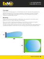
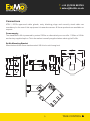
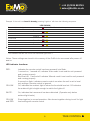
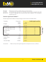
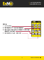
Installation and
User Manual
TAKE CONTROL
T +44 (0)1925 852745
E [email protected]
Features:
•
•
•
•
•
•
•
•
•
•
•
ATEX/IECEx Zone 1 and Zone 21 certified for use in explosive gas and dust areas
Multiple sensor / multiple light configurations are possible
Microwave Doppler technology
Ambient light level sensor
Adjustable switch on time
Adjustable sensitivity and detection range
Optional ATEX Remote control programmer
110 / 230Vac operation or 24Vdc operation
10A direct relay output
2nd 10A relay output for movement detection
Control input 12/24Vdc to override the detection sensor
For Warranty and Terms & Conditions please refer to: www.Ex-Mo.co.uk.
TAKE CONTROL
T +44 (0)1925 852745
E [email protected]
Contents
Applications. . . . . . . . . . . . . . . . . . . . . . . . . . . . . . . . . . . . . . . . . . . . . . . . . . . . . . . . . . . . . . 1
Operation. . . . . . . . . . . . . . . . . . . . . . . . . . . . . . . . . . . . . . . . . . . . . . . . . . . . . . . . . . . . . . . . 1
Coverage. . . . . . . . . . . . . . . . . . . . . . . . . . . . . . . . . . . . . . . . . . . . . . . . . . . . . . . . . . . . . . . . 2
Mounting . . . . . . . . . . . . . . . . . . . . . . . . . . . . . . . . . . . . . . . . . . . . . . . . . . . . . . . . . . . . . . . . 2
Connections, Power Supply, Mounting Bracket, Relay Output . . . . . . . . . . . . . . . . . . . . . 3-5
Installation - Setup. . . . . . . . . . . . . . . . . . . . . . . . . . . . . . . . . . . . . . . . . . . . . . . . . . . . . . . . . 6
Installation - Setup via remote control . . . . . . . . . . . . . . . . . . . . . . . . . . . . . . . . . . . . . . . . 6-9
Remote control . . . . . . . . . . . . . . . . . . . . . . . . . . . . . . . . . . . . . . . . . . . . . . . . . . . . . . . . . . 10
Specification . . . . . . . . . . . . . . . . . . . . . . . . . . . . . . . . . . . . . . . . . . . . . . . . . . . . . . . . . . . . 11
Safety Instructions . . . . . . . . . . . . . . . . . . . . . . . . . . . . . . . . . . . . . . . . . . . . . . . . . . . . . 12-18
Applications
This unit can provide energy saving by automatically switching off lights in areas that are
unoccupied.
• Movement detection in remote working areas, remote sites.
• Control lighting in infrequently used spaces.
• Alerting control centre; Detecting: people / vehicles / other moving objects.
Operation
Sensing movement by microwave, the Ex-Mo will switch on the lights for a period of time
while the area is occupied. Additionally the unit can transmit a signal to an alarm system as
an intruder alert. Roof or wall mounted with the optional adjustable bracket, several Ex-Mo
units can be paralleled to obtain a large area of coverage controlling the same lighting circuit.
Alternatively several lights can be controlled from one sensor up to the maximum 10A current.
Ex-Mo can operate a higher rated external contactor if required, or supply a signal to an
energy management system.
Adjustable on-time from 5 minutes to 60 minutes and adjustable range sensitivity. Operating
with a range of 15 to 20 metres.
1
TAKE CONTROL
T +44 (0)1925 852745
E [email protected]
Coverage
Ex-Mo has a coverage pattern of ~72° horizontally and ~36° vertically. This represents the
angular coverage where 70% of Ex-Mo’s sensitivity is maintained. In practice Ex-Mo will
detect 90° so that a single Ex-Mo placed in the corner of a rectangular room will give
complete coverage along the walls.
Mounting
Ex-Mo must be securely mounted to a fixed object. Any movement of the sensor could
activate the unit as if it were detecting a moving target.
Mount the Ex-Mo on a wall facing the direction of the area to be monitored. Using the
adjustable bracket, angle the face of the Ex-Mo toward the target area.
The high frequency radar operates best when a target is approaching or moving away from it.
The Microwave Beam is emitted from the front face and is directional. See diagram below.
3M
14M
2
TAKE CONTROL
T +44 (0)1925 852745
E [email protected]
Connections
ATEX / IECEx approved cable glands, entry blanking plugs and correctly sized cable are
mandatory for the use of this equipment in hazardous areas. All these products are available on
request.
Power supply
The standard Ex-Mo is powered by mains 230Vac or alternatively we can offer 110Vac or 24Vdc
as a factory supplied option. This information is usually supplied when ordering the Ex-Mo.
Ex-Mo Mounting Bracket
Manufactured from 3mm stainless steel. M6 clinch nuts throughout.
150
139
25
90
37
32
15
50
58
14
11
10
Ө7
45
24
84
115
15
Ө6
33
40
20
90
10
75
110
120
50
91
3
TAKE CONTROL
T +44 (0)1925 852745
E [email protected]
Relay outputs
Two output relays are provided. The relay outputs are capable of 10A continuous load each.
Breaking capacity 2500VA.
• ‘Relay 1’ operates to switch on lighting when movement is detected and it is sufficiently
dark.
• ‘Relay 2’ operates independently of the photo electric cell when movement is detected
(e.g. for security signalling).
Both relays can be configured as normally open (NO) or normally closed (NC). The factory
setting for Relay 2 is normally closed (NC), the contacts will open on motion detection or
power failure.
Both relay outputs are isolated (1000Vrms) and can be used as ‘volt free’ contacts with an
external supply not exceeding 250Vac. Useful as a signal for example into a lighting control
system or to feed a larger contactor.
Alternatively Relay 1 can power lighting directly from the internal mains supply.
4
TAKE CONTROL
T +44 (0)1925 852745
E [email protected]
Connection diagram - Typical 230 VAC connection
OVER-RIDE LIGHT
CONTROLLER
LIGHT CONTROL
1
+
2
-
Light Over-ride Relay
12 Vdc
3
Light Control Relay
Dark Sensitive
4
AUXILIARY CONTROL
VOLT FREE
CONTACTS
5
SUPPLY LIVE
7
SUPPLY EARTH
8
EARTH TO CASE
9
NEUTRAL OUTPUT
10
SUPPLY NEUTRAL
11
Auxiliary Control Relay
24 Hour
6
Normally linked
Power Supply
230Vac (110Vac* 24Vdc*)
*If configured
5
TAKE CONTROL
T +44 (0)1925 852745
E [email protected]
Installation - Setup
Ex-Mo’s parameters can be set using the internal switches or via the remote controller, follow
the relevant section below.
The equipment must be installed by skilled electricians or instructed personnel in accordance
with National Legislation and relevant technical standards.
Please read this handbook carefully before commencing installation of Ex-Mo and retain for
future reference.
Remove Ex-Mo and any accessories carefully from its packaging.
Ex-Mo can be mounted in two orientations dependent on your preferred cabling route. The
optional Ex-Mo mounting bracket must be appropriately positioned facing the target area as
described in the coverage and mounting section of this manual.
Ex-Mo can now be attached in either orientation to the fixed mounting bracket and positioned
toward the target area. Once the required position has been established all adjustment points
should now be fully tightened.
Ensure that Ex-Mo is earthed and note that the unit is not internally fused.
After loosening the retaining locking screw on the lid turn the lid anti-clockwise to remove
from the main body. For termination within the Ex-Mo unit please remove the top circuit board
by gently extending the two fixing prongs outwards. The green terminal block on the lower
circuit board can now be unplugged to aid termination.
On completion of Ex-Mo internal termination ensure that the top circuit board is re-fitted in the
correct orientation i.e. with the Ex-Mo label the correct way up.
The Ex-Mo lid can now be re-fitted ensuring that the lid is tight enough to maintain the IP
rating, remembering to tighten down the retaining locking screw.
Ex-Mo can now be installed within the recognised code of practise e.g. EN60 079
If Ex-Mo is to be set manually please refer to the Local Adjustment section of this handbook.
Installation - Setup via Remote Controller
The remote controller can be operated in the hazardous area with the lid to the unit fitted and
sealed. The remote control is directed towards the glass front and should have a range of up
to 10 metres. The Red LED quick flash indicates that the remote control signal was
acknowledged.
6
TAKE CONTROL
T +44 (0)1925 852745
E [email protected]
• For remote operation, check visually that switch 4 of the switch block on the uppermost
PCB is set to ‘on’.
Setting the Light Sensitivity- Method 1 (Pre-set Light Levels)
• Press ‘Walk Test’
• Set the light sensitivity level with the arrow keys. Refer to page 8 of the user manual for
desired setting (Level 1-5)
• The level set is indicated by the amount of times the red and yellow LED flash together.
For example; two flashes indicates that the Ex-Mo is set to level 2. Please see light Level
Indicator Chart for further options.
• You can only go up and down through the levels one at a time. For example, you cannot
go from level 1 straight to level 5.
• Set the time delay that you require. You can choose to have 5 minutes, 30 minutes or a
one hour time delay. This is the amount of time that the lights will stay on after the last
movement within the vicinity of the Ex-Mo
• Press ‘Auto Mode,’ to confirm the changes that you have made.
Setting the Light Sensitivity- Method 2 (Current Ambient Light)
• Press ‘Walk Test’
• Press ‘Light Set Now.’ The red LED will then flash on off for 2-4 seconds.
This indicates that the Ex-Mo has measured the current light ambience.
This operation will now enable the Ex-Mo to switch the lights on when movement is sensed.
This now means that if gets lighter than the measured light ambience… The Ex-Mo will
switch off the lights.
• Set the time delay that you require. You can choose to have 5 minutes, 30 minutes or a
one hour time delay. This is the amount of time that the lights will stay on after the last
movement within the vicinity of the Ex-Mo
• Press ‘Auto Mode,’ to confirm the changes that you have made.
Setting the Movement Sensitivity (Range)
• Make sure that the Ex-Mo is in ‘Auto Mode,’ (working mode).
• Either set the sensitivity up or down with the sensitivity arrows
• To test the sensitivity, either walk towards or away from the Ex-Mo. When the strobe light
goes out you know that you are out of range. This enables the installer to determine
whether to decrease or increase the movement sensitivity.
7
TAKE CONTROL
T +44 (0)1925 852745
E [email protected]
Example: If the unit is on Level 3 already, pressing ‘Light inc’ will show the following sequence.
LED SHOWN
Remote Acknowledged
2 seconds
Brief flash at button press
Count 1
2 seconds
Count 2
2 seconds
Count 3
2 seconds
Count 4
3 seconds
Back to Normal Operation
This indicates that the unit is now set to ambient light Level 4
Notes: These settings are stored in the memory of the Ex-Mo to be recovered after power off
and on.
LED indicator functions:
RED:
YELLOW:
· Indicates the remote control has been pressed, brief flash.
· 1 second on, 1 second off, indicates 'Auto mode' is set and the unit powered
and running properly.
· Brief flash on, 1 second off indicates 'Manual mode' is set and the unit powered
and running properly
· 3 second on flash, indicates remote control use when the unit is set to local
only settings. Remote control is ignored.
· On, indicates the ambient light is below the threshold level set. Off indicates
the ambient light is bright enough to switch the lights off.
WHITE:
· On, indicates that movement has been detected. (Operates only below
ambient light levels).
YELLOW
and RED:
· Show together in normal operation. Also shown together during 'count' for light
· level setting with remote control.
8
TAKE CONTROL
T +44 (0)1925 852745
E [email protected]
· These three can be on briefly during normal operation.
YELLOW
and RED
· On continuously: Indicates the 'Override relay' has been energised externally.
and WHITE: · This puts the lighting relay on permanently while energised. (For emergency
override use etc.)
Common Light Levels Outdoor**
Common light levels outdoor at day and night can be found in the table below:
Illumination
(ftcd)*
10,000
(lux)
107,527
1,000
10,752
Overcast Day (Light cloud)
325
3500
1
Overcast Day (Dark cloud)
100
1,075
2
10
107
3
1
10.8
4
0.1
1.08
5
0.01
0.108
0.001
0.0108
0.0001
0.0011
0.00001
0.0001
Sunlight
Full Daylight
Very Dark Day
Twilight
Deep Twilight
Full Moon
Quarter Moon
Starlight
Overcast Night
*foot/candles
Ex-Mo Light Level Set
**Data from http://www.engineeringtoolbox.com/light-level-rooms-d_708.html
9
TAKE CONTROL
Ex-Mo Range
Condition
T +44 (0)1925 852745
E [email protected]
10
TAKE CONTROL
T +44 (0)1925 852745
E [email protected]
Specification
Supply voltage
110 / 230Volts AC, 50 Hz
Relay 1,2 current maximum
10A 250Vac continuous each (resistive load)
Relay 1,2 Voltage maximum
250Vac
Relay 1,2 Isolation
1000Vrms
Relay 1,2 maximum breaking capacity
2500VA
Override input relay
Factory standard: 12Vdc coil 12mA rated current.
960Ohm coil
Must operate voltage 80% of max rated voltage
Must release voltage 10% of min rated voltage
Adjustable Time
Safety
5-60 minutes (remote control setting) other times
available.
II 2 G D
Ex d IIC T6 Ta -40°C to 50°C Gb
Ex tb IIIC T85°C Ta -40°C to 50°C Db IP66
Current capability
10A x 2 Open contact relays selectable NC or
NO operation
Temperature range
Ambient -40°C to 50°C
Fixing
Flat surface mounting or with optional swivel and
tilt bracket
Conformity
ATEX / IECEx / CE
Remote control unit
ATEX IS approved
11
TAKE CONTROL
T +44 (0)1925 852745
E [email protected]
ATEX / IECEX
Safety Instructions
Distributor and Approvals Details
The Ex-Mo is distributed and maintained solely by:
Ex-Mo JV Limited
2-6 Gawsworth Court
Risley Road
Birchwood
Warrington
Cheshire WA3 6NJ
United Kingdom
Telephone: +44 (0)1925 852745
Fax: +44 (0)1925 820803
Email: [email protected]
The Ex-Mo system has the following specific approvals:
Name and Type
ATEX Certificate Number
IECEx Certificate Number
Specific Marking of Explosion (GAS)
Specific Marking of Explosion (DUST)
ATEX Directive Marking
Ex-Mo: Motion Detection System
Baseefa11ATEX0005
IECEx BAS 11.0002
Ex d IIC T6 Ta -40°C to +50°C Gb
Ex tb IIIC T85°C Ta -40°C to +50°C Db IP66
II 2 G D
Notified body
CE1180
Instructions for Safety
The equipment must be installed by skilled electricians or instructed personnel in accordance
with National Legislation and relevant technical standards.
The equipment must NOT be operated in Zone 0 hazardous area.
The technical data listed on the enclosure label must be observed.
Changes to the design of the equipment are not permitted.
The equipment shall only be operated as intended and only in an undamaged condition.
No parts of the equipment are user-serviceable.
12
TAKE CONTROL
T +44 (0)1925 852745
E [email protected]
Signed
EC Declaration of Conformity
Anthony G. McCormick
ATEX Manager
Orange Instruments Limited
Harmonised Standards
EN 60079-0:2009
EN 60079-1:2007
Notified Body
Baseefa 1180
Rockhead Business Park
Staden Lane, Buxton
Derbyshire SK17 9RZ
United Kingdom
Description
The Ex-Mo comprises of an Ex d enclosure, containing an electronic assembly. All field and
customer wiring is to the Ex d enclosure and the cover of the Ex d enclosure is only removed for
commissioning and periodic adjustment. Detailed instructions on the wiring, first time use and
normal operation of the system are described in the accompanying electronics system manual:
Ex-Mo - USER MANUAL ALC-020
Normal Use
The Ex-Mo normally operates within a Hazard Zone 1 / 21. All electrical signals to and from the unit
are protected by suitable cables, glands and conduits. In normal use the unit emits a signal and
receives a reflection from an object. By this means it can determine whether to switch the relays to
control lighting or alarm triggers.
Installation and Calibration
The Ex-Mo must be installed and commissioned by suitably trained personnel. Normally, the unit is
mounted and wired to a fixed position on a building; if this is not the case then specific instructions
will be provided. The user is required to make electrical connections to their systems according to
the wiring instructions in the accompanying manual using suitable cables and connection
components. No changes to the equipment or the wiring instructions are permitted. Following
connection, and with no hazard present, the unit may be powered up to adjust the sensitivity and
other settings. If the electronics are set to “Remote Control” use, the glass cover lid may be fitted
and the unit sealed for hazardous operation while still allowing adjustment via the remote control
through the window.
13
TAKE CONTROL
T +44 (0)1925 852745
E [email protected]
Maintenance
The cover on the Ex d enclosure must not be removed when a hazardous atmosphere is present.
The unit must be left for 30 minutes with power off before the cover is removed. With access to the
instrument, it is possible to modify the configuration according to the accompanying manual. In
the event of suspected damage to the electronic assembly, the circuit boards can be unclipped
and removed. The internal chassis plate carrying the instrument can be removed by unscrewing
the rear terminal connectors from the power circuit board, removing the circuit board,
unscrewing the securing fixings, and removing. The instrument should be packed in antistatic
material and sent to the Manufacturer for evaluation. No part of the system is user-serviceable.
Zone of Operation
The Ex-Mo can be used hazardous area Zone 1 where a hazardous atmosphere is likely to occur
occasionally. The equipment must not be installed in a Zone 0 area. The enclosure is protected to
a liquid ingress rating of IP66 - it is dust-tight and can withstand liquids exposure equivalent to
heavy seas, if the Ex d enclosure lid threads are liberally coated with a conductive lubricant.
Physical Description
Overall Size
145 x 132 x 129
Weight
2.5kg (Ex d enclosure), 1.5kg (Aluminium enclosure)
Material
Aluminium in yellow chromating and chemical resistant paint (outside only)
or 316L Stainless Steel
Equipment rating IP66 – Ex d enclosure lid threads liberally coated with conductive lubricant
Earth point
Right hand side M5 internal/external bolt (provided)
Cable entries
In the Ex d enclosure base. Unused entries must be plugged with
Ex d certified plugs.
14
TAKE CONTROL
T +44 (0)1925 852745
E [email protected]
IR900 Infra-red Controller User Handbook
Distributor and Approvals Details
The IR900 is manufactured and maintained solely by:
Ex-Mo JV Limited
2-6 Gawsworth Court
Risley Road
Birchwood
Warrington
Cheshire WA3 6NJ
United Kingdom
Telephone: +44 (0)1925 852745
Fax: +44 (0)1925 820803
Email: [email protected]
The IR900 has the following specific approvals
Name and Type:
Certificate Number:
Specific Marking of Explosion Protection:
ATEX Directive Marking:
Notified body:
INFRA-RED CONTROLLER TYPE IR900
Baseefa 03ATEX0187X
EEx ia IIC T4 (-20ºC ≤Ta ≤ +40ºC)
II 1 G
Baseefa (2001) 1180
General Description
The IR900 handheld infra red controller is designed for use with the Ex-Mo motion sensor. It
can be used freely within a hazardous area to calibrate and configure this instrument via a
window in their flameproof enclosures without having to purge the area of hazardous gases
or liquids.
Full details of this interactive use of the IR900 are described in the individual positioner
handbooks.
15
TAKE CONTROL
T +44 (0)1925 852745
E [email protected]
Zone of Operation
The IR900 is an intrinsically safe device approved for operation in the following environment
according to Specific Marking of explosion protection:
EEx ia IIC T4 (-20°C ≤Ta ≤ +40°C)
Ta = ambient temperature
IEC CENELEC
North America
Zone 0 – continuous hazard present
Division 1
Gas Group – IIC (hydrogen, acetylene, carbon disulphide)
Class 1A (Hydrogen)
Class 1B (acetylene)
Surface temperature – T4 135ºC – Ambient temperature -20ºC to +40ºC
Physical Description
Size – 63mm wide, 113mm high, 31mm deep
Weight – 0.25kg
Enclosure – die cast aluminium, nylon coated
Switch membrane – polyester
Equipment rating – IP40
First Time Use
The IR900 is supplied fully tested with a battery pack fitted, ready for immediate use.
Normal Use
The top end of the IR900 (with the projecting IR emitter) should be aimed at the window in the
flameproof enclosure housing the equipment to be controlled. Changes in state of indicators
behind the window will show correct reception of the IR pulse train from the IR900. The IR900
should be used within 2 metre of the window and it might be necessary to temporarily shade
the window under intense ambient light conditions.
Maintenance
The outside of the enclosure can be cleaned using a damp cloth. Do not use solvents.
Do not unscrew the four enclosure retaining screw when a hazard is present. Apart from
battery changes there are no user serviceable parts within the IR900. Suspected faulty units
must be returned to the Manufacturers.
16
TAKE CONTROL
T +44 (0)1925 852745
E [email protected]
Changing the Battery Pack
The battery pack will last for at least 3 years with normal use. Replacement at 2 years is
recommended.
The following work MUST be carried out in a SAFE environment with no hazard present.
1)
2)
3)
4)
5)
6)
7)
Have the replacement pack to hand.
Remove the four posi head screws securing the enclosure back.
Remove the enclosure back exposing the battery pack and printed circuit board.
Remove the old battery pack and unplug from printed circuit.
Plug in new battery pack noting the polarising tab on the circuit board connector.
Replace enclosure back and secure with the four screws.
Dispose of the old battery pack (manganese) according to local environmental
regulations.
Specification
Size:
Enclosure:
Switch membrane:
Enclosure retainers:
Weight:
Equipment rating:
63mm wide, 113mm high, 31mm deep
Die cast aluminium, nylon coated
Polyester
4 screws M3 x 10 posi countersunk
0.25kg
IP40
Quiescent current:
Running current:
Infra red wavelength:
Radiated Intensity:
26µA (no key pressed)
400µA (key pressed)
940nm
15.4mW/sr
Battery Pack terminal voltage:
Battery Pack size:
Battery Pack connection:
Battery weight:
9V nominal
52mm long x 28mm wide x 19.5mm deep
Polarised 0.1” 2-way free socket
0.1kg
17
TAKE CONTROL
T +44 (0)1925 852745
E [email protected]
EC Declaration of Conformity
Signed
Anthony G. McCormick
ATEX Manager
Orange Instruments Limited
Manufacturer
Notified body
Orange Instruments Limited
Lower Farm Road
Moulton Park
Northampton NN3 6XF
United Kingdom
Baseefa
Rockhead Business Park
Staden Lane, Buxton
Derbyshire SK17 9RZ
United Kingdom
Harmonised Standards
EN 50014 A1 A2: 1997
EN 50020: 2002
Equipment description
Infra-Red Controller
Type IR900
II 1 G EEx ia IIC T4
(-20°C≤Ta≤+40°C)
Other Standards
EN 50284: 1999
18
TAKE CONTROL
T +44 (0)1925 852745
E [email protected]
TAKE CONTROL
Ex-Mo JV Ltd
2-6 Gawsworth Court, Risley Road
Birchwood, Warrington, Cheshire WA3 6NJ
T 01925 852745 | F 01925 820803
www.Ex-Mo.co.uk | [email protected]
Rev.01 02/12