1
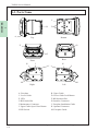
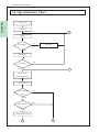
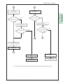
CHAPTER 1 Introduction 1-1. Main Features 1-2. Prior to Use 1-3. Parts Name 1-4. System Configuration 1-5. Operation Flow Chart Issue: 02/2006 TAIKO Service Manual 1-1. Main Features CHAPTER 1 In this section, TAIKO unit’s main features are explained. Easy Installation Installation/removal of TAIKO unit is very easy in the clip-on style. Anyone can install the TAIKO unit easily. Data Scanning Frequency Data Scanning frequency can be selected with DIP Switch. Once or twice is selectable. The acceptance rate can be improved by setting it twice. Anti-Picking Function TAIKO unit is an Anti-Picking functionequipped bill acceptor. It can prevent from the picking such as a note with attached thread by rotating the dram. Once or 5 times is selectable. It is selected with DIP Switch. It prevent from the fishing more by setting it 5 times Palm Programmable Taiko unit can connect Palm (Palm’s Tungsten C). Software program can be downloaded from palm easily at the field. LED Pattern Selectable LED pattern can be changed with DIP Swithc depending on your circumstances. Pattern 1 or 2 is selectable. © 2006 Japan Cash Machine Co.Ltd. All rights reserved. 1-2 TAIKO Service Manual 1-2. Prior to Use Be sure to follow these steps when creating the project for TAIKO unit. 1 Before using TAIKO unit, check the all required hardware is present and read all specification, wiring, and installation infromation. See => CHAPTER 2 Specifications or CHAPTER 3 Installation/Operation 2. Panel Cut Out Creat the panel cut out on the door to install the TAIKO unit. See => 2-6. Panel Cut Dimensions 3. Setting Set the DIP switch depending on the connected host machine or the features of TAIKO unit you want to use. See => 2-7. DIP Switch Setting 4. Installation Install the TAIKO unit and connect the harness with the host mashine. See=> CHAPTER 2 Specifications, or CHAPTER 3 Installation/Operation 5. Operation Supply the power to the TAIKO unit. © 2006 Japan Cash Machine Co.Ltd. All rights reserved. 1-3 CHAPTER 1. Preperation TAIKO Service Manual 1-3. Parts Name CHAPTER 1 C D B A Bottom Top G E F Rear Front I H J K L M M Right Left A. Faceplate C. Lower Guide E. LED G. Bill Outlet Slot I. Maintenance Connector J. Upper Guide Open/Close Button L.DIP Switch B. Upper Guide D. Lower Guide Lock Button F. Bill Insertion Slot H. Interface Connector J. Faceplate Installation Guide K. Optional Connector M. Faceplate Guide © 2006 Japan Cash Machine Co.Ltd. All rights reserved. 1-4 TAIKO Service Manual 1-4. System Configuration The following diagram represents the standard items can be connected to the TAIKO unit. TAIKO Unit Interface Connector Maintenace Connector TAIKO Harness B (EDP# 116488, Part# 3280-03-11) PC (Windows2000/XP) TAIKO Harness A (EDP# *******, Part# 3280-05-51) JCM Power Supply Unit (EDP# 116125, Part# VM-30) Harness *1 Host Machine (Game Machine etc.) *1 Communication harness needs to be prepared by custmer. © 2006 Japan Cash Machine Co.Ltd. All rights reserved. 1-5 CHAPTER 1 PDA (Palm’ s Tungsten C) TAIKO Service Manual 1-5. Operation Flow Chart CHAPTER 1 Power ON Initializing B Idling Accept Bill? NO LED OFF YES LED ON NO Insert Bill? YES C Transport Bill (Scanning Bill Date) Stop Feeding Bill Validation NO OK? YES Inhibited Bill? YES NO Output Denomi Signal A D © 2006 Japan Cash Machine Co.Ltd. All rights reserved. 1-6 TAIKO Service Manual A D Carry Out Bill Reject Bill (Carry Out to Cashbox) Completed 㧫 YES YES Retry Rejection Retry Carrying Out NO Completed? NO Completed? YES YES B B Output VEND Signal Completed B Stop LED Red Blink *1 *1 Stop LED Red Blink *1 Turn the pouwer OFF and clear the jammed bill. Then supply the power again. © 2006 Japan Cash Machine Co.Ltd. All rights reserved. 1-7 CHAPTER NO 1 Completed? NO TAIKO Service Manual CHAPTER 1 NOTE © 2006 Japan Cash Machine Co.Ltd. All rights reserved. 1-8