1
MA782
Service Manual
TABLE OF CONTENTS
SERVICE WARNING·····································1
A. I M P O R T A N T S A F E T Y I N S T R U C T I O N · · · · · · · · · · · · · · · · · · · · · 1
B. S P E C I F I C A T I O N S · · · · · · · · · · · · · · · · · · · · · · · · · · · · · · · · · · · · · · 2
C. T I M I N G C H A R T · · · · · · · · · · · · · · · · · · · · · · · · · · · · · · · · · · · · · · 3
D. C O N T R O L L O C A T I O N · · · · · · · · · · · · · · · · · · · · · · · · · · · · · · · · · 5
E. CONDUCTION VIEW···································6
F. ADJUSTMENT PROCEDURE····························11
G. T R O U B L E S H O O T I N G H I N T S · · · · · · · · · · · · · · · · · · · · · · · · · · · 1 2
H. B L O C K D I A G R A M · · · · · · · · · · · · · · · · · · · · · · · · · · · · · · · · · · · · · 1 6
I. S C H E M A T I C D I A G R A M · · · · · · · · · · · · · · · · · · · · · · · · · · · · · · · · 1 7
WARNING
To prevent from fire or shock hazard,do not expose monitor to any rain or any form of water.High voltage is
inside the monitor so please do not remove the back cover of the cabinet if you are not a qualified
monitor engineer.Contact the local dealer or the nearest Proview branch office if you need help.
A. IMPORTANT SAFETY INSTRUCTION
Prior to using this service manual,please ensure that you have carefully followed all the procedures outlined in
the user's manual for this product.
1. Read all of these instructions.
2. Save these instructions.
3. Follow all warnings and instructions a marked on the product.
4. Unplug this product from the wall outlet before cleaning.Do not use liquid cleaners or aerosol
cleaners, use a damp cloth for cleaning.
5. Do not use this product near water.
6. Do not place this product on an unstable cart,stand or tablle.The product may fall,causing serious
damage to the product.
7. Slots and openings in the cabinet and the back or bottom are provided for ventilation,to ensure
reliable operation of the product and to protect it from overheating,those openings must not be
blocked or covered.The openings should never be blocked by placing the product on a bed,sofa, rug,
or other similar surface.This product should not be placed in a built-in installation less proper
ventilation is provided.
8. This products should be operated from the type of power source indicated on the marketin label.
If you are not sure of the type of power available, consult your dealer or local power company
9. This product is equipped with a 3-wire grounding type plug,a plug having a third (grounding)
pin.This plug will only fit into a grounding-type power outlet.This is a safety feature,if you are
unable to insert the plug into the outlet,contact your electrician to replace your obsolete outlet.Do
not defeat the purpose of the grounding-type plug.
10. Do not allow anything to rest on the power cord.Do not locate this product where persons will walk
on the cord.
11. If an extension cord is used with this product,make sure that the total of the ampere ratings on the
product plugged into the extension cord to the waplugged into outlet does not exceed 15 ampere.
12. Never push objects of any kind into this product through cabinet slots as they may touch dangerous
voltage points or short out parts that could result in a risk of fire or electric shock.Never spill liquid
of any kind on the product.
13. Do not attempt to service this product yourself,as opening or removing covers may expose you to
dangerous voltage points or other risks.Refer all servicing to service personnel.
14. Unplug this product from the wall outlet and refer servicing to qualified service personnel under the
following conditions.
a. When the power cord or plug is damaged or frayed.
b. If liquid has been spilled into the product.
c. If the product has been exposed to rain or water.
d. If the product does not operate normally,when the operating instructions are followed.Adjust
only those controls that are covered by the operating instructions since improper adjustment of
other controls may result in damage and will often require extension work by a qualified
technician to restore the product to normal operation.
e. If the product has been dropped or the cabinet has been damaged.
f. If the product exhibits a distinct change in performance,indicating a need for service.
B. SPECIFICATIONS
1. Maximum Resolution
2. Recommend Resolution
3. Synchronization Range
Horizontal
Vertical
4. Active Display Area
5. Dot Pitch
6. Support display colors
7. Contrast Ratio (Typical)
8.Luminance of White
9. Bandwidth
10. User Control
11. OSD Function
CR=5
12. View Angle
Horizontal
Vertical
13. Power Source
14. Power Consumption
15. Connection Type
16. Input Signal
Video
Sync.
17. Color Temperature
18. Dimension (WxHxD)
19. Monitor Weight
20. Base Operation
Tilt
21. Power Saving
ON
STAND BY
OFF
1280*1024 @ 75Hz
1280*1024 @ 60Hz
30 – 81 KHz
56– 75 Hz
337.9mm (H) x 270.3mm (V)
0.264(H) x 0.264(V) mm
16.7M color
450:1
260cd/m²
135MHz
4 Key Switch
Brightness, Conrast, H-Pos, V-Pos, H. Size, Phase, Color Select,
Auto, Reset, Language, OSD Adjust, Exit
+-70 Degrees
+-70 Degrees
90-264 Vac 60 / 50 Hz
48W (max.)
15 Pin D Type
Analog R.G.B. , 0.7Vp-p / 75 Ohms
TTL level,positive or negative polarity
Cool / Warm
452mm x 465mm x 142mm
4.8Kg
0 / + 15 degree
< 50W
< 5W
< 5W
22. Signal Connector Pin Assignment
Pin No.
23. Audio signal
1. Red
2. Green
3. Blue
4. Ground
5. Self Test
6. Red Ground
7. Green Ground
8. Blue Ground
3.5Φ stereo phone jack
Input Sensitivity : 200mV
2.5+2.5W 8Ω Speaker
9. VDD from PC for DDC
10. Sync. Ground
11. Ground
12. SDA (For DDC)
13. Horizontal Sync.
14. Vertical Sync.
15. SCL (For DDC)
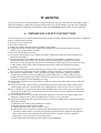
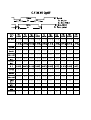
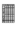
C.TIMING CHART
Video
B
D
E
Sync.
A
C
Preset
Modes
A: Period
B: Active
C: Sync Width
D: Back Porch
E: Front porch
VGA
640X480
*VGA
640X480
VESA
640X480
VESA
640X480
VGA
720X400
VESA
800X600
VESA
800X600
VESA
800X600
VESA
800X600
*MAC
832X624
Dot Rate
25.175MHz 31.340MHz 31.500MHz 31.500MHz 28.322MHz 36.000MHz 40.000MHz 50.000MHz 49.500MHz 55.000MHz
F.H
31.469KHz 34.978KHz 37.861KHz 37.500KHz 31.469KHz 35.156KHz 37.879KHz 48.077KHz 46.875KHz 49.107KHz
A-period
31.778us
28.590us
26.413us
26.667us
31.777us
28.444us
26.400us
20.800us
21.333us
20.364us
B-Active
25.422us
20.421us
20.317us
20.317us
25.422us
22.222us
20.000us
16.000us
16.162us
15.127us
C-Sync.width
3.813us
2.042us
1.270us
2.032us
3.813us
2.000us
3.200us
2.400us
1.616us
2.182us
D-Back
1.589us
3.063us
3.810us
3.810us
1.907us
3.556us
2.200us
1.280us
3.232us
1.745us
0.954us
3.064us
1.016us
0.508us
0.635us
0.666us
1us
1.12us
0.323us
1.31us
F . V
59.941Hz
66.625Hz
72.810Hz
75.000Hz
70.087Hz
56.250Hz
60.317Hz
72.188Hz
75.000Hz
75.087Hz
A-Period
16.683ms
15.009ms
13.734ms
13.333ms
14.268ms
17.778ms
16.579ms
13.853ms
13.333ms
13.318ms
B-Active
15.253ms
13.723ms
12.678ms
12.800ms
12.711ms
17.067ms
15.840ms
12.480ms
12.800ms
12.707ms
C-Sync.width
0.064ms
0.086ms
0.079ms
0.080ms
0.064ms
0.057ms
0.106ms
0.125ms
0.064ms
0.061ms
0.794ms
1.115ms
0.528ms
0.427ms
1.112ms
0.626ms
0.607ms
0.478ms
0.448ms
0.428ms
0.572ms
0.085ms
0.449ms
0.026ms
0.381ms
0.028ms
0.026ms
0.77ms
0.021ms
0.122ms
-
-
-
-
+
+
+
+
-
Porch
E-Front
Porch
D-Back
Porch
E-Front
Porch
H/V
SYNC
Interlaced
-
NON
-
NON
-
NON
-
NON
- +
NON
+
NON
+
NON
+
NON
+
NON
-
NON
Preset
Modes
VESA
VESA
VESA
VESA
VESA
1024X768 1024X768 1024X768 1280X1024 1280X1024
Dot Rate
65.000MHz
75.000MH
78.750MHz 108.00MhZ 135.00MHz
z
F.H
48.363KHz
56.476KH
60.023KHz 63.98KHz 79.976KHz
z
A-period
20.677us 17.707us 16.660us
15.630us
12.504us
B-Active
15.754us 13.653us 13.003us
11.852us
9.481us
2.092us
1.813us
1.219us
1.037us
1.067us
2.462us
1.920us
2.235us
2.296us
1.837us
0.369us
0.321us
0.203us
0.444us
0.119us
F . V
60.004Hz 70.069Hz 75.029Hz
60.020Hz
75.025Hz
A-Period
16.666ms 14.272ms 13.328ms
16.661ms
13.329ms
B-Active
15.880ms 13.599ms 12.795ms
16.005ms
12.804ms
0.124ms
0.106ms
0.050ms
0.047ms
0.038ms
0.600ms
0.513ms
0.466ms
0.594ms
0.475ms
0.062ms
0.054ms
0.017ms
0.016ms
0.013ms
-
-
+
+
+
C-Sync.width
th
D-Back
Porch
E-Front
Porch
C-Sync.width
D-Back
Porch
E-Front
Porch
H/V
SYNC
Interlaced
-
NON
-
NON
+
NON
+
NON
+
NON
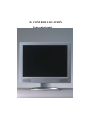
D. CONTROL LOCATION
Font control panel
1.
2.
3.
4.
5.
Power Button
2. LED (Power Display)
Menu Button
Select Button
Auto Button
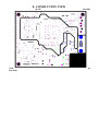
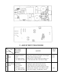
E. CONDUCTION VIEW
MAIN
(Com
nent Side)
BOARD
po
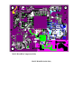
MAIN BOARD (Component Side)
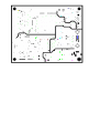
MAIN BOARD (Solid Side)
F. ADJUSTMENT PROCEDURE
ITEM
Program Menu.
B+
Check
A
﹟Test Meter
﹡Test Point
﹫Pattern
﹟Digital Voltmeter
﹡CN7
﹫Crosshatch Pattern
(31.5KHz,640x480)
Power Saving ﹟Wattmeter
Check
﹟PC or Pattern
B
generator
﹫Crosshatch Pattern
(31.5KHz,640x480)
Operation
1. Plug power cable into the adapter, check adapter
power indicator light up green.
2. Make sure the voltage of the power plug (CN7)
on the main PCB to the value shown at right.
1. Unplug the signal cable into the monitor.
2. Turn the power switch of the monitor ON.
3. Check monitor power indicator light up orange.
4. Make sure the wattmeter value shown at right.
5. OSD will be display “NO SIGNAL” Picture.
Check
Value
12.0V
±0.2V
‹ 2.5W
Into Factory ﹟PC or Pattern
mode
generator
C
﹫Crosshatch Pattern
(31.5KHz,640x480)
Auto mode
Check
﹟PC or Pattern
generator
﹫Crosshatch Pattern
(1024x768/60Hz)
1. Press and relese the MENU knob to activate the
OSD menu.
2. Move the OSD to the AUTO function,press MENU
key auto adjuat display mode to its utmost
performance according to VGA setting.
3. In the event of the display image needs further
adjustment
White
Balance
Adjust
﹟PC or Pattern
generator
﹫White Pattern
(1024x768/60Hz)
1. Move the OSD to the COLOR mode (AUTO COLOR).
2. set color is 9300°K using the OSD,Check the value
shown at right.
Y = 220±0.1FL x = 0.283±0.01 y = 0.297±0.01
3. set color is 6500°K using the OSD,Check the value
shown at right.
Y = 220±0.1FL x = 0.313±0.01 y = 0.329±0.01
﹟PC or Pattern
generator
1. Move the OSD to the LANGUAGE mode.
2. You can choose one of the eight language you need.
D
E
1. Hold ‹ key,then turn the power switch of the
monitor OFF.
2. Hold › key,then turn the power switch of the
monitor ON.
3. You can into factory adjustment mode.
OSD
F Language
Setting
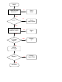
G. TROUBLE SHOOTING HINTS
No Display
( Black )
LED ON ?
YES
NO
Power
adapter ?
NO
Change
adapter
YES
Push the power
ON/OFF switch
LED Color
change ?
Back light
ON?
To Step 2
YES
YES
NO
NO
Check main
board U2/Pin2
Check the CN1/Pin1
of Inverter
Hi / Lo under
push power
sw?
+12V ?
High Voltage !
NO
YES
Make sure the
connection of
Inverter is fine
YES
NO
A
To Step 2
NO
Display ?
Check
F1(Fuse) of inverter
YES
B
Nice Job !
A
B
Check the
connection of
CN8 cable
NO
Change the
main board
Hi / Lo under
push power
sw?
YES
Display ?
YES
NO
Change the
Inverter
Nice Job !
Display ?
Change the
main board
NO
To Step 2
YES
Nice Job !
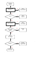
Step 2
Check the main
board 12V ?
NO
Check
F1,D5
YES
NO
Check
U10,U11,TR1
+5.0 V ?
YES
Check the main
board U7 / Pin 5 ?
YES
Check
U7
YES
H/V input
Signal ?
YES
Change
U9
NO
Check
H/V Signal
Display ?
YES
Nice Job !
NO
Change
Signal Cable
No display
(White)
Check the main
board 5V ?
NO
Check
U10,U11,TR1
NO
Check
U8,U13
YES
+3.3V ?
YES
Check the main
board U9/Pin3 ?
NO
Check
3.3V Circuit
YES
YES
H/V Input
Signal ?
Change
U9
NO
Check
H/V Signal
Display ?
YES
Nice Job !
.
NO
Change
Signal Cable
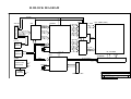
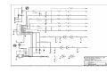
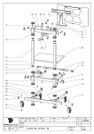
H. BLOCK DIAGRAM
VSYNC
HSYNC
VGA-IN
12PIN
C
O
N
N
E
N
T
SCALER
ADC
8 R0~R7
LVDS
10 EVEN
8 RA0~RA7
LCD PANEL(LVDS)
8 GA0~GA7
3 {R.G.B}
8 G0~G7
8 BA0~BA7
DDC-SDA
DDC-SCL
8 B0~B7
D-DE
8 RB0~RB7
D.D.C
24C21
LVDS
8 GB0~GB7
EEPROM
CRYSTAL
10 ODD
8 BB0~BB7
24C16
HI VOLTAGE
12M HZ
EEPROM
MCU
INVERTER
SDA
SCL
POWER
SWITCH POWER
SUPPLY AND
REGULATOR
8PIN
3V
5V
CRYSTAL
12V
POWER
ADAPTER
BLK-ON/OFF
BRIGHTNESS
12M HZ
12V
12V
C
O
N
N
E
N
T
Title
FUNCTION KEY
Size
B
Date:
BLOCK DIAGRAM
Rev
B
Document Number
ORION
Tuesday, October 23, 2001
Sheet
1
of
1
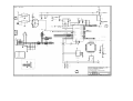
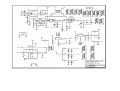
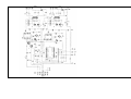
I.SCHEMATIC DIAGRA
.
Memu.