1
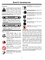
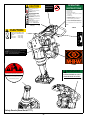
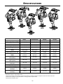
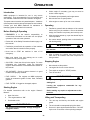
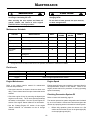
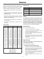
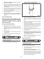
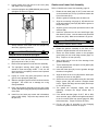
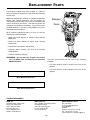
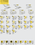
OPERATOR’S SAFETY
AND SERVICE MANUAL
R420
This manual covers the following serial numbers
and higher for each model listed:
420R . . . . . . . . . . . . . . . . . . . . . 4200395
420H . . . . . . . . . . . . . . . . . . . . . 4250487
420HC . . . . . . . . . . . . . . . . . . . . 4271101
SMART RAMMERS
MBW, Inc.
MBW (UK) Ltd.
250 Hartford Rd • PO Box 440
Slinger, WI 53086-0440
Phone: (262) 644-5234
Fax: (262) 644-5169
Email: [email protected]
Website: www.mbw.com
Units 2&3 CochraneStreet
Bolton BL3 6BN
Phone: 01404 387784
Fax: 01204 387797
MBW FRANCE S.A.R.L.
Z.A. d’Outreville
11 rue Jean Baptiste Néron,
60540 BORNEL
FRANCE
Teléfono: +33 (0) 3 44 07 15 96
Fax: +33 (0) 3 44 07 41 28
Correo electrónico: [email protected]
L16770 / 06.08.T
©MBW, Inc. 2006
Printed in the USA
TABLE OF CONTENTS
Safety Information . . . . . . . . . . . . . . . . . . . . . . 1
Introduction . . . . . . . . . . . . . . . . . . . . . . . . . . . . . . . . . 1
Safety Precautions . . . . . . . . . . . . . . . . . . . . . . . . . . . 1
Safety Decals . . . . . . . . . . . . . . . . . . . . . . . . . . . . . . . 1
Torque Chart . . . . . . . . . . . . . . . . . . . . . . . . . . . . . . . 7
Service Tools . . . . . . . . . . . . . . . . . . . . . . . . . . . . . . . 7
General. . . . . . . . . . . . . . . . . . . . . . . . . . . . . . . . . . . . 7
Handle Removal. . . . . . . . . . . . . . . . . . . . . . . . . . . . . 7
Engine Removal . . . . . . . . . . . . . . . . . . . . . . . . . . . . . 7
Specifications. . . . . . . . . . . . . . . . . . . . . . . . . . 3
Operation . . . . . . . . . . . . . . . . . . . . . . . . . . . . . 4
Clutch Removal . . . . . . . . . . . . . . . . . . . . . . . . . . . . . 8
Gearbox Removal . . . . . . . . . . . . . . . . . . . . . . . . . . . 8
Gearbox Disassembly . . . . . . . . . . . . . . . . . . . . . . . . 8
Introduction . . . . . . . . . . . . . . . . . . . . . . . . . . . . . . . . . 4
Gearbox Assembly . . . . . . . . . . . . . . . . . . . . . . . . . . . 9
Before Starting & Operating . . . . . . . . . . . . . . . . . . . . 4
Lower Unit Disassembly. . . . . . . . . . . . . . . . . . . . . . 10
Starting Engine . . . . . . . . . . . . . . . . . . . . . . . . . . . . . . 4
Lower Unit Assembly . . . . . . . . . . . . . . . . . . . . . . . . 10
Operating . . . . . . . . . . . . . . . . . . . . . . . . . . . . . . . . . . 4
Gearbox and Lower Unit Assembly . . . . . . . . . . . . . 11
Stopping Engine . . . . . . . . . . . . . . . . . . . . . . . . . . . . . 4
Parts Replacement Cycles and Tolerances . . . . . . . 12
Lifting and Transporting . . . . . . . . . . . . . . . . . . . . . . . 4
Maintenance . . . . . . . . . . . . . . . . . . . . . . . . . . . 5
Replacement Parts . . . . . . . . . . . . . . . . . . . . . 13
Gearbox Assembly . . . . . . . . . . . . . . . . . . . . . . . . . . 14
Maintenance Schedule . . . . . . . . . . . . . . . . . . . . . . . . 5
Lower Unit Assembly . . . . . . . . . . . . . . . . . . . . . . . . 16
Fluid Levels. . . . . . . . . . . . . . . . . . . . . . . . . . . . . . . . . 5
Gearbox and Lower Unit Assembly . . . . . . . . . . . . . 18
Engine Maintenance . . . . . . . . . . . . . . . . . . . . . . . . . . 5
Handle Assembly . . . . . . . . . . . . . . . . . . . . . . . . . . . 20
Engine Speed . . . . . . . . . . . . . . . . . . . . . . . . . . . . . . . 5
Handle Assembly . . . . . . . . . . . . . . . . . . . . . . . . . . . 22
Checking Percussion System Oil . . . . . . . . . . . . . . . . 5
Engine Assembly . . . . . . . . . . . . . . . . . . . . . . . . . . . 24
Changing Percussion System Oil . . . . . . . . . . . . . . . . 6
Service . . . . . . . . . . . . . . . . . . . . . . . . . . . . . . . 7
Warranty . . . . . . . . . . . . . . . . . . . . . . . . . . . . . 26
This page intentionally left blank.
SAFETY INFORMATION
Introduction
SAFE DRESS: Do not wear loose clothing,
rings, wristwatches, etc. near machinery.
This Safety Alert Symbol is used to call attention
to items or operations which may be dangerous
to those operating or working with this
equipment.
The symbol can be found
throughout this manual and on the unit. Please read these
warnings and cautions, along with all decals, carefully
before attempting to operate the unit. Make sure every
individual who operates or works with this equipment is
familiar with all safety precautions.
NOISE PROTECTION: Wear OSHA specified
hearing protection devices.
EYE PROTECTION: Wear OSHA specified
eye shields, safety glasses, and sweat bands.
FOOT PROTECTION: Wear OSHA specified
steel-tipped safety shoes.
WARNING
HEAD PROTECTION: Wear OSHA specified
safety helmets.
GENERAL WARNING.
Indicates information
important to the proper operation of the
equipment. Failure to observe may result in
damage to the equipment and/or severe bodily
injury or death.
DUST PROTECTION: Wear OSHA specified
dust mask or respirator.
CAUTION
OPERATOR: Keep children and bystanders
off and away from the equipment.
GENERAL CAUTION.
Indicates information
important to the proper operation of the
equipment. Failure to observe may result in
damage to the equipment.
REFERENCES: For details on safety rules and regulations
in the United States, contact your local Occupational Safety
and Health Administration (OSHA) office. Equipment
operated in other countries must be operated and serviced
in accordance and compliance with any and all safety
requirements of that country. The publication of these
safety precautions is done for your information. MBW does
not by the publication of these precautions, imply or in any
way represent that these are the sum of all dangers present
near MBW equipment.
If you are operating MBW
equipment, it is your responsibility to insure that such
operation is in full accordance with all applicable safety
requirements and codes. All requirements of the United
States Federal Occupational Safety and Health
Administration Act must be met when operated in areas that
are under the jurisdiction of that United States Department.
Safety Precautions
LETHAL EXHAUST GAS: An internal
combustion engine discharges carbon
monoxide, a poisonous, odorless, invisible
gas. Death or serious illness may result if
inhaled. Operate only in an area with proper
ventilation.
NEVER OPERATE IN A
CONFINED AREA!
DANGEROUS FUELS: Use extreme caution
when storing, handling and using fuels, as
they are highly volatile and explosive in vapor
state. Do not add fuel while engine is running.
Stop and cool the engine before adding fuel.
DO NOT SMOKE!
Safety Decals
SAFETY GUARDS: It is the owner's
responsibility to ensure that all guards and
shields are in place and in working order.
Carefully read and follow all safety decals. Keep them in
good condition. If decals become damaged, replace as
required. If repainting the unit, replace all decals. Decals
are available from authorized MBW distributors. Order the
decal set listed on the following page(s).
IGNITION SYSTEMS: Breakerless, magneto,
and battery ignition systems can cause severe
electrical shocks. Avoid contacting these
units or their wiring.
-1-
CAUTION
Read the Operating Instructions
before operating this piece of
equipment.
Keep unauthorized and untrained
people away from this
equipment.
14781
ROTATING & MOVING PARTS!
Make sure all guards and safety
devices are in place.
Wear approved hearing protection,
foot protection, eye protection and
head protection.
STOP
! "
# $
SHUT OFF the motor before servicing or cleaning.
% &'
( &'
DO NOT RUN in an enclosed area.
The engine produces carbon
monoxide, a POISONOUS GAS.
) &
Failure to comply could result in serious
bodily injury.
13483
13483
14773
CAUTION
Machine is top heavy and
could fall if not lifted from
this bar.
14769
420=
440/270/450=
460/470/480=
#119 (54kg)
#143 (65kg)
#160 (73kg)
14769
14770
!
"
06079
01
32
6
01064
DANGER
PELIGRO
Compressed spring could cause severe injury.
See manual for disassembly instructions.
La primavera comprimida podría causar
la herida severa. Consulte el libro para
ver el desmontaje correcto.
15137
01326
Safety Decals (Decal Set #17777)
-2-
SPECIFICATIONS
420H
420HL
421HC
420R
420HC
420R
420H/420HC
420HL
421HC
Operating Weight - lbs(kg)
118 (53.5)
126 (57.1)
134 (60.8)
128 (58.1)
Height - in(cm)
38.25 (97.2)
38.25 (97.2)
38.25 (97.2)
38.25 (97.2)
Width - in(cm)
14.25 (36.2)
14.25 (36.2)
14.25 (36.2)
14.25 (36.2)
Length - in(cm)
26 (66)
26.88 (68.3)
28.25 (71.8)
26.88 (68.3)
Engine
Robin EH09
Honda GX100
Honda GX100
Honda GX100
Shoe (W x L)
in(cm)
10 x 11.5
(25.4 x 29.2)
10 x 11.5
(25.4 x 29.2)
10 x 11.5
(25.4 x 29.2)
11 x 13
(28 x 33)
Operating Noise Level1 dBa
93 dBA
93 dBA
93 dBA
93 dBA
Compaction Force
lbf(kN)
3000 (13.3)
per blow
3100 (13.8)
per blow
3200 (13.8)
per blow
3200 (13.8)
per blow
Travel Speed
ft/min(m/min)
55 (16.8)
55 (16.8)
55 (16.8)
55 (16.8)
Compaction Area
sqft/hr (sqm/hr)
2520 (234)
2520 (234)
2520 (234)
2772 (257)
Percussion Rate
blows/min
up to 720
up to 720
up to 720
up to 720
Engine Speed rpm
3500-3600
3500-3600
3500-3600
3500-3600
Fuel Capacity - gal(L)
1.1 (4.2)
1.1 (4.2)
1.1 (4.2)
1.1 (4.2)
Gearbox Oil Capacity
ounces(L)
10 (0.3)
10 (0.3)
10 (0.3)
10 (0.3)
Engine Oil Capacity
ounces(L)
10 (0.3)
9.6 (0.28)
9.6 (0.28)
9.6 (0.28)
Specifications subject to change without notice
1. Noise levels are taken at the operating position and are based on operating conditions. Background noise will increase noise levels.
2. Noise level is operating on loose gravel surface. Hearing protection may be needed.
3. Not all product variations shown.
-3-
OPERATION
Introduction
4.
MBW equipment is intended for use in very severe
applications. They are powered by four cycle engines and
are available in different sizes and a selection of engines.
Choke engine if necessary (you may not need to
choke a warm engine).
5.
Pull starter rope repeatedly until engine starts.
6.
Move choke lever to open position.
7.
Allow engine to warm up for one or two minutes.
This parts manual contains only standard parts. Variations
of these parts as well as other special parts are not included.
Contact your local MBW distributor for assistance in
identifying parts not included in this manual.
Operating
1.
Familiarize yourself with the balance of the rammer
before using it in job conditions. Due to the inherent
design, the machine is top heavy and could tip over.
2.
After the engine warms up, open the throttle fully for
normal operation.
3.
On uneven terrain, pushing down on the handle will
aid climbing ability.
Before Starting & Operating
• REMEMBER! It is the owner’s responsibility to
communicate information on the safe use and proper
operation of this unit to the operators.
• Review ALL of the Safety Precautions listed on page 1 of
this manual.
WARNING
• Familiarize yourself with the operation of the machine
and confirm that all controls function properly.
Do not bear down (body weight of operator) on
the machine.
• Know how to STOP the machine in case of an
emergency.
4.
• Make sure hands, feet, and clothing are at a safe
distance from any moving parts.
After 3 passes, the rammer may have more kick
back, this is an indication that ideal compaction is
being reached.
Stopping Engine
• OIL LEVEL - Check the oil level in the engine. For more
information see “Lubrication” under the respective
engine’s “Owners Manual” or the Maintenance section of
this manual.
• AIR CLEANER - Check to ensure element is in good
condition and properly installed.
1.
Move throttle to idle position.
2.
Let engine idle for one or two minutes.
3.
Turn switch on engine to “STOP” position.
4.
Turn off fuel valve.
• FUEL SUPPLY - The engines on MBW equipment
require an automotive grade of clean, fresh, unleaded
gasoline.
Always stop the engine before:
• FUEL FILTER - If clogged or damaged, replace.
Adding fuel.
WARNING
Starting Engine
Leaving the equipment unattended for any
amount of time.
For detailed instructions refer to the engine “Owner’s
Manual”.
Before making any repairs or adjustments to the
machine.
1.
Open fuel valve.
2.
Turn engine switch to “ON”.
3.
Set throttle to idle.
Lifting and Transporting
1.
The unit may be lifted by the handle and engine
guard.
CAUTION
2.
The unit should be transported laying face down
The engine speed must NOT be high enough to
engage the clutch.
3.
Secure it in place by the handle and shoe. DO NOT
lay the unit on its sides or face up during transport.
-4-
MAINTENANCE
WARNING
CAUTION
Always exercise the stopping procedure before
servicing or lubricating the unit.
Always verify fluid levels and check for leaks after
changing fluids.
After servicing the unit, replace and fasten all
guards, shields, and covers to their original
positions before resuming operation.
Do not drain oil onto ground, into open streams,
or down sewage drains.
Maintenance Schedule
SYSTEM
MAINTENANCE
DAILY
Air Cleaner
Check and clean
X
Engine
Refer to engine operator/owner manual
X
Hardware
Check and tighten as needed1
In Line Fuel Filter
Replace
Percussion
System
Check oil level
EVERY 25
HOURS
EVERY 300
HOURS
X
X
X
X
X
X
X
Change oil2
Shockmounts
Check for cracks or deterioration
Spark Plug
Replace
1.
2.
YEARLY
X
X
X
Check all hardware after the first 5 hours of use, then follow the maintenance schedule.
Change oil in lower unit after the first 50 hours of operation, then follow the maintenance schedule.
Fluid Levels
SYSTEM
FLUID VOLUME
RECOMMENDED OIL
Percussion System
10 oz
SF SAE 10W-30 Motor Oil
Engine
Refer to engine operator/owner manual
Engine Maintenance
Engine Speed
Refer to the engine owner’s manual for maintenance
intervals and procedures.
Engine speed is factory set according to the speed listed in
the Specifications section of this manual. Refer to the
engine owners manual for procedure on setting operating
speed if necessary.
• Check and clean the air cleaner element at least once
daily, The air cleaner has a foam pre-cleaner that can be
washed.
Checking Percussion System Oil
• Check the engine oil level by removing the dipstick (the
engine must be level). The oil level should be between
the marks on the dipstick. See the “Check Engine Oil”
section of the engine “Owner’s Manual” for information.
Refer to Lower Unit Assembly, page 16.
The rammer percussion system and gearbox are lubricated
by an oil mist which is formed and carried throughout the
rammer by a pumping action in the machine's lower system.
• See the “Change Engine Oil” section of the engine
“Owner’s Manual” for information on the oil change
intervals.
1.
-5-
Before daily operation, place the rammer on a flat
surface and check the oil level in the glass sight (#2)
on the springbox guard (#11).
2.
If the oil is not visible in the sight gauge, add oil as
required. See Fluid Levels for recommeneded type
of oil.
Changing Percussion System Oil
Refer to Lower Unit Assembly, page 16.
1.
Remove the drain plug (#4) above the sight glass (#2)
on the back of the springbox guard (#9).
2.
Place an oil drain pan behind the shoe and tip the
rammer back so the handle is on the ground.
3.
Elevate the shoe until the lower assembly is
horizontal.
Hold this position until the oil is
completely drained.
-6-
4.
With the handle still on the ground, remove the four
hex head flange screws (page 18, #8) holding the
cover (page 18, #2) to the gearbox (page 18, #4).
5.
Remove the cover, the cover gasket (page 18, #6),
and the dowel pins (page 18, #1) from the gearbox.
6.
Tip the unit forward and drain any oil into an oil pan.
7.
After the oil has drained out, replace the dowel pins,
gasket, and cover and secure with the four hex head
flange screws.
8.
Tip the rammer onto it’s face and fill according to the
Fluid Levels section in this manual.
9.
Replace the drain plug.
SERVICE
Assembly and disassembly should be performed by a
service technician who has been factory trained on MBW
equipment. The unit should be clean and free of debris.
Pressure washing before disassembly is recommended.
Service Tools
01629
Rubber Test Mat
• Prior to assembly, wash all parts in a suitable cleaner or
solvent.
06468
Springbox Tool
07205
Bellows Installation Tool
07353
Clutch Removal Tool
07552
Blind Hole Bearing Puller Tool
Part No.
• Check moving parts for wear and failure. Refer to the
Replacement section in this manual for tolerance and
replacement cycles.
• All shafts and housings should be oiled prior to pressing
bearings. Also, ensure that the bearings are pressed
square and are seated properly.
General
The disassembly and assembly procedures given on the
next few pages are intended for a complete dismantling of
the rammer. Read the following sections carefully. It is not
necessary to follow the complete disassembly procedure
when only partial disassembly is required. If repairs have to
be made to the Lower Assembly only, it is recommended
that the drive unit (engine, gearbox and handle) be removed
from the lower unit. See “Lower Unit Disassembly”.
• All bearings should be replaced when rebuilding any
exciter or gearbox.
• All gaskets and seals should be replaced after any
disassembly.
Torque Chart
SIZE
1/4-20
1/4-28
5/16-18
5/16-24
3/8-16
3/8-24
7/16-14
7/16-20
1/2-13
1/2-20
9/16-12
5/8-11
5/8-18
3/4-16
1-8
1-14
1-1/2-6
M6
M8
M 10
GRADE 2
GRADE 5
49 in•lbs
76 in•lbs
56 in•lbs
87 in•lbs
8 ft•lbs
13 ft•lbs
9 ft•lbs
14 ft•lbs
15 ft•lbs
23 ft•lbs
17 ft•lbs
26 ft•lbs
24 ft•lbs
37 ft•lbs
27 ft•lbs
41 ft•lbs
37 ft•lbs
57 ft•lbs
41 ft•lbs
64 ft•lbs
53 ft•lbs
82 ft•lbs
73 ft•lbs
112 ft•lbs
83 ft•lbs
112 ft•lbs
144 ft•lbs
200 ft•lbs
188 ft•lbs
483 ft•lbs
210 ft•lbs
541 ft•lbs
652 ft•lbs
1462 ft•lbs
3 ft•lbs
4 ft•lbs
6 ft•lbs
10 ft•lbs
10 ft•lbs
20 ft•lbs
CONVERSIONS
in•lbs x 0.083 = ft•lbs
ft•lbs x 12 = in•lbs
ft•lbs x 0.1383 = kg•m
ft•lbs x 1.3558 = N•m
Description
Handle Removal
GRADE 8
9 ft•lbs
10 ft•lbs
18 ft•lbs
20 ft•lbs
33 ft•lbs
37 ft•lbs
52 ft•lbs
58 ft•lbs
80 ft•lbs
90 ft•lbs
115 ft•lbs
159 ft•lbs
180 ft•lbs
315 ft•lbs
682 ft•lbs
764 ft•lbs
2371 ft•lbs
7 ft•lbs
18 ft•lbs
30 ft•lbs
Refer to Handle Assembly, page 20.
1.
Turn the fuel valve (#11) to the "off" position.
2.
Loosen the hose clamp (#3) at the engine end of the
fuel line (#9). Disconnect the fuel line.
3.
Remove the hardware holding the throttle (#8) to the
handle (#21 or #24).
4.
Remove the four flange head cap screws and flange
bolts (#28 & #30) securing the handle to the torsion
mounts (#6).
5.
Lift the handle from the rammer.
Engine Removal
NOTE: It is not necessary to remove the handle to take
the engine off the machine.
Refer to Engine Assembly, page 24.
For 420R machines with Robin EH09 engine
-7-
1.
Follow steps 1 through 3 under "Handle Removal".
2.
Remove the two metric hex head flange screws
(page 20, #35) securing the engine guard (page 20,
#16) to the engine adapter plate (#5).
3.
While supporting the engine (#6), remove the four
hex nuts and lockwashers (#19 & #13) holding the
engine to the adapter plate.
4.
Remove the engine and engine guard from the
rammer.
7.
For 420H and 420HC machines with Honda GX100
engine
1.
Follow steps 1 through 3 under "Handle Removal".
2.
Remove the four metric hex head flange screws
(page 20, #36) securing the engine guard (page 20,
#20) to the engine (#7).
3.
While supporting the engine, remove the four hex
flange nuts (#12) holding the engine and engine
adapter plate (#9) to the studs (#8).
4.
Remove the engine, engine adapter plate, and
engine guard from the rammer.
Insert the setscrew into the piston pin (#5) and
remove the piston pin. See Figure 1.
Figure 1
Clutch Removal
8.
Remove the six hex head flange screws (page 16,
#19) holding the springbox guard (page 16, #9) to the
bottom bellows ring (page 16, #3).
9.
Remove the gearbox assembly from the lower unit
assembly. See Figure 2.
Refer to Engine Assembly, page 24.
1.
Remove the jam nut and key. Slide the clutch off
engine crank.
2.
Reinstall the clutch. Carefully insert woodruff key
making sure key remains aligned with keyway
3.
Reinstall jam nut with medium strength thread locker
and tighten to 60 ft lbs (N•m).
Gearbox Removal
NOTE: It is necessary to remove the Handle and the
Engine to remove the Gearbox.
Refer to Gearbox and Lower Unit Assembly, page 18.
1.
Drain the oil from the rammer following steps 1
through 3 under “Changing Percussion System Oil”
on page 6.
2.
Replace the drain plug.
3.
Remove the four hex head flange screws (#8) holding
the cover (#2) to the gearbox (#4).
Figure 2
CAUTION
Gearbox Disassembly
NOTE: There may be oil in the gearbox. Tip the
unit back when removing the cover from the
gearbox.
Refer to Gearbox Assembly, page 14.
Crank Gear Removal
4.
Remove the cover, the cover gasket (#6), and the
dowel pins (#1) from the gearbox.
5.
Tip the unit forward and drain any oil into an oil pan.
6.
Loosen the hex nut (#10) on top of the ram head and
remove the setscrew (#9).
-8-
1.
Slip a retaining ring pliers through the slot opening in
the crank gear (#20) and remove the retaining ring
(#10) from the housing. The retaining ring will remain
between the crank gear and the bearing.
2.
Remove the SAE plug (#19) from the rear of the
gearbox. Use a 3/8 in (10mm) diameter steel rod to
press the crank gear out of the gearbox.
3.
Remove the ball bearing (#2) from the crank gear
using a bearing puller. Remove the large retaining
ring (#1) from the back of the crank gear.
4.
Remove the small retaining ring (#9) from the front of
the offset shaft on the crank gear and remove the
connecting rod (#5).
5.
Remove the needle bearing (#6) from the gearbox
with a blind hole bearing puller tool (MBW #07552).
Pinion Removal
1.
Remove the external retaining ring (#4) from the gear
end of the pinion (#21) on the inside of the gearbox.
If the retaining ring is pinched in its groove, tap the
pinion on the drum side. This will relieve the pressure
on the retaining ring.
2.
Press out the pinion.
3.
Pry out the oil seal (#11) and discard.
4.
Remove the retaining rings (#10 & #18).
5.
Use a bearing puller to remove the ball bearings (#2
& #22).
Remove the hex head cap screw (#29) from the top
of the breather assembly (#14).
2.
Remove the plain washer (#30), cap (#17) and filter
(#15).
3.
Press a new oil seal (#11) into the gearbox. Make
sure the oil seal is pressed in straight.
4.
Lightly oil the lip of the oil seal and the shaft portion of
the pinion (#21). Carefully press the pinion into the
gearbox.
5.
Install a retaining ring (#4) onto the pinion from inside
the gearbox.
6.
Press the needle bearing (#6) into the gearbox. The
bearing must be pressed in with the numbers and
letters facing up. Apply a light coat of oil (see Fluid
Levels, page 5 for proper oil type) to the needle
bearing after installation.
7.
Place a retaining ring (#10) over the large shaft of the
crank gear (#20). Press the ball bearing (#2) onto the
crank gear.
8.
Install a retaining ring (#1) to secure the ball bearing.
9.
Press the bearing (#3) into the connecting rod (#5)
and secure with a retaining ring (#8).
Use a pipe wrench to remove the breather tube (#16).
Do not disassemble the breather assembly.
10. Press the connecting rod onto the offset shaft of the
crank gear.
Slide Bearing Removal
1.
Remove the retaining ring (#25) from the bottom of
the gearbox guide tube.
2.
Remove the hex head cap screw (#28) securing the
tube to the gearbox. Heating the cap screw may be
necessary to loosen the high strength thread locking
compound. On later model machines, cap screw
(#28) may not need to be removed to disassemble
slide bearings.
11. Install a retaining ring (#9) to secure the connecting
rod.
12. Press the crank gear assembly into the gearbox.
Install the snap ring (#10) using a retaining ring pliers
inserted through the slot in the crank gear.
13. Install the SAE plug (#19) into the gearbox. Do not
over tighten.
Slide the slide bearings (#23 & #26) out of the
gearbox guide tube.
14. Replace the breather sub-assembly (#16), filter
(#15), cap (#17), and plain washer (#30). Apply
medium strength thread locking liquid to the threads
of the hex head cap screw (#29) and install.
CAUTION
15. Slide the slide bearing with the hole (#23) into the
gearbox tube and align the hole in the bearing with
the access hole in the gearbox.
Do not scratch or gouge the gearbox guide tube
walls.
16. Apply high strength thread locker to the hex head cap
screw (#28) thread it into the tapped hole above the
access hole.
Bellows Removal
1.
Loosen the four hex head flange screws (page 18,
#7) securing the upper bellows ring (page 16, #8) to
the gearbox.
2.
Slide the bellows, upper bellows ring, lower bellows
ring, and flange screws off the gearbox.
CAUTION
The cap screw must thread in completely.
Gearbox Assembly
17. Insert the other slide bearing (#26).
18. Secure with the internal retaining ring (#25).
Refer to Gearbox Assembly, page 14.
1.
3.
Do not use excessive pressure to seat the pinion.
CAUTION
3.
Press the large ball bearing (#2) into the gearbox
from the back. Secure with a retaining ring (#10).
CAUTION
Breather Removal
1.
2.
19. Assemble the lower bellows ring (page 16, #3) to one
side of the bellows (page 16, #5).
Press the small ball bearing (#22) into the gearbox
from the back. Secure with a retaining ring (#18).
-9-
20. Assemble the upper bellows ring (page 16, #8) to the
other side of the bellows.
2.
Insert the springbox tool (MBW #06468) rods into the
springbox assembly as shown in Figure 3.
21. Insert four hex head flange screws (page 18, #7)
through the upper bellows mount so the head of the
screw is wedged between the bellows and the upper
bellows mount.
22. Slide the bellows, bellows rings, and hex head flange
screws over the gearbox guide tube with the upper
bellows ring toward the gearbox.
23. Thread the hex head flange screws into the gearbox
to secure the bellows.
24. Apply a light coat of oil (see Fluid Levels, page 5 for
proper oil type) to all bearings after installation is
complete.
Figure 3
Lower Unit Disassembly
NOTE: The lower unit can be separated from the drive
unit (engine, gearbox and handle) without completely
disassembling the rammer. If the lower unit has not
already been separated, follow the “Gearbox
Removal” instructions.
Refer to Lower Unit Assembly, page 16.
Shoe and Springbox Guard Removal
1.
Remove the four hex head cap screws and
lockwashers (page 18 #11 & #12) that secure the
lower unit assembly (page 18 #3) to the shoe (page
18 #13).
2.
Remove the shoe.
3.
Lift the springbox guard off the springbox and ram
head assembly.
4.
Remove the o-ring (#13) from the springbox guard.
3.
Make sure the rods are 180° apart.
4.
Place the washers over the rods and run the nuts
down so the washers are snug against the cover
(#12).
5.
Remove the flat head socket screws (#18) holding
the cover to the springbox.
6.
While holding the bottom of the rods from turning,
slowly and evenly back off the nuts on the cover side.
7.
After the tension is removed from the cover, the
springbox tools and the cover can be removed.
8.
Remove the o-ring (#1) from the cover.
9.
The lower springs (#6 & #7) can be removed from the
springbox (#15).
10. Place a drift pin or steel rod through the piston hole in
the ram head (#17). Use this to hold the ram head
from turning while removing the hex head cap screw
and lockwasher (#20 & #21).
Springbox Disassembly
11. Remove the washers (#110), piston (#11), spacer
(#114), and upper springs (#6 & #7).
WARNING
Working with compressed springs! Failure to
follow the next set of steps very carefully could
result in injury or death.
1.
Lower Unit Assembly
WARNING
Working with compressed springs! Failure to
follow the next set of steps very carefully could
result in injury or death.
Flip the springbox assembly upside down.
Refer to Lower Unit Assembly, page 16.
- 10 -
1.
Turn springbox (#15) up side down and insert the
upper springs (#6 & #7).
2.
Install the ram head (#17) and add the washers (#10),
the piston (#11), and the spacer (#14).
3.
Apply medium strength thread locker to the hex head
cap screw (#20) and install it, along with a lockwasher
(#21), into the ram head. Torque to 50 ft lbs (68 N•m).
4.
Insert the lower springs (#6 & #7).
5.
Lightly grease the o-ring groove in the cover (#12)
and install a new o-ring (#1).
6.
Insert the springbox tool (MBW #06468) rods into the
springbox as shown in Figure 4.
Gearbox and Lower Unit Assembly
Refer to Gearbox and Lower Unit Assembly, page 18.
Rotate the ram head (page 16, #17) in the lower unit
so the threaded hole on top is positioned toward the
front of the shoe (#13).
2.
Slide the gearbox assembly onto the lower unit.
3.
Align the connecting rod (page 14, #5) with the ram
head and install the piston pin (#5) with the groove in
the pin facing out.
4.
Align the groove in the piston pin with the hole for the
setscrew (#9).
5.
Install the setscrew into the ram head finger tight,
then back off 1/4 turn. Lock the setscrew in place with
the hex nut (#10). Make sure setscrew is in groove.
CAUTION
Figure 4
7.
1.
Slowly draw the cover down onto the springbox by
alternately tightening each rod.
WARNING
Keep the cover level with the springbox.
The piston pin must be able to rotate.
6.
Rotate the gearbox assembly so the front of the
gearbox is aligned with the front of the lower unit.
7.
Secure the lower bellows mount to the springbox
guard using six hex head flange screws (page 16,
#19). Torque to 12 ft lbs (16 N•m).
8.
Secure the cover with two flat head socket screws
(#18) torqued to 8 ft lbs (11 N•m).
8.
Apply a light coat of oil to all of the bearings in the
gearbox assembly.
9.
Remove the springbox tool rods from the assembly.
9.
Tip the assembly back and place a new gasket (#6)
over the gearbox face.
10. The springbox warning decal (page 2, #01326)
should be clean and highly visible. If not, the old
decal should be completely removed and replaced
with a new decal.
11. Lightly oil a new o-ring (#13) and place it into the
groove in the springbox guard (#9).
12. Slide the springbox guard over the ram head onto the
springbox. Be careful not to damage the o-ring
during installation.
13. Place the springbox assembly onto the shoe (page
18 #13) with the fill plug (#4) pointing toward the back
of the shoe.
14. Install four hex head cap screws and lockwashers
(page 18 #21 & #22). Torque the cap screws to 40 ft
lbs (56 N•m).
10. Insert the dowel pins (#1) into the gearbox through
the holes in the gasket.
11. Align the holes in the cover (#2) with the dowel pins
and place the cover on the gasket.
12. Secure the cover to the gearbox using four hex head
flange screws (#8) with medium strength thread
locker. Tighten the flange screws equally and torque
to 12 ft lbs (16 N•m).
13. The gasket will compress slightly after initial
tightening, re-torque the flange screws after 5
minutes.
14. If the handle brackets (page 20, #17, #22 or #23)
were removed, apply medium strength thread locker
to the four socket head cap screws (page 20, #29)
before assembly. Torque to 35 ft lbs (47 N•m).
15. Fill the unit with oil according to the Changing
Percussion System Oil section on page 6.
- 11 -
Parts Replacement Cycles and Tolerances
Bearings
Replace anytime a bearing is rough, binding, discolored or removed from housing or
shaft.
Bellows
Replace when they are worn, cracked, or to the point of leaking.
Clutch
Replace clutch if shoes and/or springs show signs of heat damage or if it does not
disengage below 2000 rpm.
Crank Gear
Replace if teeth are cracked or if they become sharp.
Engine Components
Refer to your engine manufacturer’s Owner’s Manual.
Guide Bushings
Replace if a 0.025” (0.635 mm) feeler gauge can be slid between the springbox and
the guide tube.
Hardware
Replace any worn or damaged hardware as needed. Replacement hardware should
be grade 5 and zinc plated unless otherwise specified.
Pinion
Replace if teeth are cracked or if they become sharp. Replace if the drum is scored
or gouged deeper than 0.03” (0.76 mm).
Piston (Springbox)
Replace if a 0.025” (0.635 mm) feeler gauge can be slid between the springbox and
the piston.
Piston Pin
Replace if the outside diameter is less than 0.620” (15.75 mm).
Piston Washers
Replace if washers are dished.
Safety Decals
Replace if they become damaged or illegible.
Seals & Gaskets
Replace if a leak is detected and at every overhaul or teardown.
Springs
Replace if a flat spot on the side of a spring is greater than 0.09” (2 mm). Replace if
the free length is less than 6.75” (171 mm). Replace ALL springs at the same time.
Replace if inner diameter is larger than, 0.890” (22.7 mm)
Springbox Bushing (Bronze) Prior to serials: 4270632-420HC
4200387-420R
service limit is 0.853” (21.7 mm)
4250661-420H
- 12 -
REPLACEMENT PARTS
The warranty is stated in this book on page 17. Failure to
return the Warranty Registration Card renders the warranty
null and void.
MBW has established a network of reputable distributors/
dealers with trained mechanics and full facilities for
maintenance and rebuilding, and to carry an adequate parts
stock in all areas of the country. Their sales engineers are
available for professional consultation. If you cannot locate
an MBW distributor in your area, contact MBW or one of our
Sales Branches listed below.
Stamped
Decal
When ordering replacement parts, be sure to have the
following information available:
• Model and Serial Number of machine when ordering
MBW parts
• Model and Serial Number of engine when ordering
engine parts
• Part Number, Description, and Quantity
• Company Name, Address, Zip Code, and Purchase
Order Number
• Preferred method of shipping
REMEMBER - You own the best! If repairs are needed,
use only MBW parts purchased from authorized
MBW distributors.
The unit’s serial number can be found in the following
locations:
• The serial number decal is located on the top of the
gearbox.
• The serial number is also stamped on the top of the
gearbox.
Write Model Number here
Write Serial Number here
Contact Information
MBW, Inc.
MBW (UK) Ltd.
250 Hartford Rd • PO Box 440
Slinger, WI 53086-0440
Phone: (262) 644-5234
Fax: (262) 644-5169
Email: [email protected]
Website: www.mbw.com
Unit 6, Bradley Fold Trading Estate
Radcliffe Moor Road
Bolton BL2 6RT, England
Phone: 01204 387784
Fax: 01204 387797
- 13 -
MBW FRANCE S.A.R.L.
Z.A. d’Outreville
11 rue Jean Baptiste Néron,
60540 BORNEL
FRANCE
Teléfono: +33 (0) 3 44 07 15 96
Fax: +33 (0) 3 44 07 41 28
Correo electrónico: [email protected]
14
17
13
19
30
29
15
27
12
16
1
2
20
6
10
21
5
11
10
3
2
18
8
4
24
28
9
23
7
26
25
Gearbox Assembly
- 14 -
22
ITEM
1.
2.
3.
4.
5.
6.
7.
8.
9.
10.
11.
12.
13.
14.
15.
16.
17.
18.
19.
20.
21.
22.
23.
24.
25.
26.
27.
28.
29.
30.
PART NO.
01001
01103
01105
01244
06161
06259
06262
06264
06265
06266
06274
06413
06423
06904
06905
06908
06910
09476
09618
13733
15959
16021
16304
16315
16451
16745
F01PW
F061605FWS
F081304HCS
F08SW
DESCRIPTION
RETAINING RING, EXT. 5100-137
BEARING, BALL
BEARING, BALL
RETIANING RING, EXT. 5160-112
ROD ASSEMBLY, CONNECTING
BEARING, NEEDLE
BUSHING
RETAINING RING, INT. N5000-187
RETAINING RING, EXT. 5100-78
RETINAING RING, INT. N5000-281
SEAL
VALVE
SPRING, COMPRESSION, 0.420 OD
BREATHER ASSEMBLY (Includes items 12, 13, 15, 16, 17, 29, 27, 30)
FILTER, BREATHER
TUBE, BREATHER
COVER
RETAINING RING, INT. N500-244
FITTING, PLUG PARKER 4HP50N
GEAR
PINION
BEARING, BALL
BEARING, SLIDE, CUT
GEARBOX***
RETAINING RING, INTERNAL, 3.0”
BEARING, SLIDE
WASHER,5/32 X 3/8 X 18 GA ZP
FLANGE HEAD CAP SCREW, 3/8-16 X 5/8 GR5 ZP
HEX HEAD CAP SCREW, 1/2-13 X 1/2 GR5 ZP
WASHER, 9/16 X 1-3/8 X 12 GA ZP
***INCLUDES GEARBOX TUBE. GEARBOX TUBE NOT AVAILABLE SEPARATELY.
- 15 -
QTY
1
2
1
1
1
1
1
1
1
2
1
1
1
1
1
1
1
1
1
1
1
1
1
1
1
1
1
1
1
1
Lower Unit Assembly
- 16 -
ITEM
1.
2.
3.
4.
5.
6.
7.
8.
9.
10.
11.
12.
13.
14.
15.
16.
17.
18.
19.
20.
21.
22.
23.
24.
PART NO.
06239
06457
07154
09618
11694
16305
16306
16311
16320
16323
16324
16325
16330
16423
17172
16317
19618
17416
18475
16326
18524
F042005FSS
F042006FWS
F072020HCS
F072022HCS
F07LW
F081318HCS
F08LW
DESCRIPTION
O-RING, 3.36 ID X 0.139 DIA
GAGE, VIEW
RING, CLAMPING, LOWER
FITTING, PLUG PARKER 4HP50N
BELLOWS, 4 PLY
SPRING, COMPRESSION, 2.313 OD
SPRING, COMPRESSION, 1.700 OD
RING, CLAMPING, UPPER
GUARD, SPRINGBOX
WASHER, 2.125 OD X 0.516 ID
PISTON
COVER, SPRINGBOX
O-RING, 2.72 ID X 0.139 DIAMETER
SPACER
SHOE, 10”, 15o
SHOE, 10”, 12o (420R ONLY)
SHOE, 11” CAST IRON (421 MODELS) (INCLUDES ITEMS #21 & 22)
SPRING BOX
BUSHING
BUSHING (For use with serial #4270632 - 420HC, 4200387 - 420R, 4250661 - 420H
and below)
SHAFT, RAM 420
FSS, 1/4-20 x 5/8”
FWLS, 1/4-20x3/4 ZP
HHCS, 7/16-20 X 2-1/2 GR5 ZP ( For cast iron shoes #19618 only)
HHCS, 7/16-20 X 2-3/4 GR5 ZP ( For aluminum shoes #17172 & 16317 only)
LOCKWASHER, 7/16 ZP
HHCS, 1/2-13 x 2-1/4 GR5 ZP
LOCKWASHER, 1/2 ZP
***Prior to 420H serial no. 4250150 & 420R serial no. 4200300, order
replacement kit #17423 (Includes items 9,15)
19620
SPRING BOX ASM. (INCLUDES ITEMS 1, 6, 7, 10 thru 14, 16 thru19, 23 & 24)
- 17 -
QTY
1
1
1
1
1
2
2
1
1
2
1
1
1
1
1
1
1
1
1
1
1
2
10
4
4
4
1
1
Gearbox and Lower Unit Assembly
- 18 -
ITEM
1.
2.
3.
4.
5.
6.
7.
8.
9.
PART NO.
07203
16313
16334
16349
16361
19619
19617
F051807FWS
F051810SSSD
F0518HN
16896
16934
16935
DESCRIPTION
PIN,DOWEL 1/4 x 1/2
COVER, RAMMER GEARBOX
GEARBOX ASSEMBLY (See page 14 for breakdown)
PIN, GROOVED
GASKET, COVER
LOWER UNIT, 420
LOWER UNIT, 421
FLANGE SCREW,5/16-18 x 7/8 ZP
SOCKET HEAD SET SCREW, 5/16-18UNC X1.25LG DOG PT
NUT,HEX 5/16-18 ZP
OPTIONAL ACCESSORIES
EXTENSION, TRENCH SHOE, 6”
KIT, 4” TRENCH SHOE
KIT, 6” TRENCH SHOE
- 19 -
QTY
2
1
1
1
1
1
1
4
1
1
Handle Assembly
- 20 -
ITEM
1.
2.
3.
4.
6.
7.
8.
9.
10.
11.
12.
13.
14.
15.
16.
17.
18.
19.
20.
21.
22.
23.
24
25.
26.
27.
28.
30.
31.
32.
33.
34.
35.
36.
38.
39.
40.
PART NO.
01035
17720
01045
01052
01145
07351
07916
14715
15183
16303
16414
16572
16573
16586
16666
14714
16671
16754
17162
17170
18527
18879
17477
17478
17481
18881
F033206PMS
F0332HN
F042004FWS
F051808FWS
F0518FN
F081305HCS
F081306HCS
M12ETLW
M08C020FWS
M08C025FWS
DESCRIPTION
QTY
HOSE, FUEL 6” LONG (420H only)
1
HOSE, FUEL 7-1/2” LONG (420R and 420HC only)
1
FILTER, FUEL, IN-LINE
1
CLAMP, HOSE
4
CLAMP, SPRING
1
TORSION MOUNT
2
FERRULE, THROTTLE LEVER
1
THROTTLE, RATCHET STYLE
1
HOSE, FUEL 1-1/2” LONG
1
TANK, FUEL
1
VALVE, FUEL
1
CASING, 30" THROTTLE WIRE
1
WIRE, 34.5" THROTTLE
1
GROMMET, 1/2”
1
CAP, 1-3/4” (USE ON ROBIN AND HONDA FLOAT CARBURATOR ENGINES)
1
CAP, 1-3/4” (USE ON HONDA DIAPHRAGM CARBURATOR ENGINES)
GUARD, ENGINE (420R only)
1
BRACKET, HANDLE (420H only)
2
SUB-HANDLE (420H only)
1
SHOCKMOUNT (420H only)
2
GUARD, ENGINE
1
HANDLE (420H only)
1
BRACKET, HANDLE, LEFT (420R and 420HC only)
1
BRACKET, HANDLE, RIGHT (420R and 420HC only)
1
HANDLE (420R & 420HC ONLY)
1
HANDLE (420R & 420HC ONLY) SERIAL NO. (4200395 420R/4271101 420HC) AND UP
1
PAN HEAD MACHINE SCREW, #10-32 x 3/4” LG ZP
1
NUT, HEX #10-32 ZP
1
FLANGE SCREW, 1/4”-20 x 1/2” ZP
4
FLANGE SCREW, 5/16”-18 x 1” ZP
12
NUT, FLANGE 5/16”-18 ZP
8
HEX HEAD CAP SCREW, 1/2”-13 x 5/8” ZP
2
HEX HEAD CAP SCREW, 1/2”-13 x 3/4” ZP
2
LOCKWASHER, M12, EXTERNAL TOOTH, ZP
4
FLANGE SCREW, M8-1.25 x 20MM ZP
4
FLANGE SCREW, M8-1.25 x 25MM ZP
4
17602
KIT, TACHOMETER
FLAT
HEAD SCREW, #10-24x1/4”, SERIAL NO. (4200395 420R/4271101 420HC) AND UP
F032402FSS
18742
THROTTLE, FLANGE MOUNT, SERIAL NO. (4200395 420R/4271101 420HC) AND UP
- 21 -
2
1
Handle
- 22 -
ITEM
1.
2.
3.
4.
5.
6.
7.
PART NO.
18511
07351
18510
18515
18883
F051808FWS
F0518FN
DESCRIPTION
HANDLE SUPPORT, LEFT
TORSION MOUNT
HANDLE SUPPORT, RIGHT
SNUBBER
RAMMER HANDLE
FLANGE SCREW, 5/16”-18 x 1” ZP
NUT, FLANGE 5/16”-18 x 7/8
- 23 -
QTY
1
2
1
2
1
12
8
ROBIN EH09
2
1
HONDA GX100
7
16
17
Install with high strength
Loctite (red).
21
10
8
12
23
22
24
18
9
Engine Assembly
- 24 -
ITEM
1.
2.
3.
5.
7.
8.
9.
10.
12.
13.
14.
15.
16.
17.
18.
19.
20.
21.
22
23
24
PART NO.
01581
06026
16433
16450
DESCRIPTION
SPRING (See note below)
KIT,SHOE & SPRING (Includes item 1 and three shoes, see note below)
ADAPTER, EH09
ENGINE ASSEMBLY, EH09 (Includes items 22, 23 and 24. Also
includes items 7, 12, 13, and 40 on page 20)
17196
ENGINE ASSEMBLY, GX100 (FLOAT CARBURATOR)
(Includes items 9, 10, 16, 17, 22, 23 & 24. Also includes 7, 12 ,13, & 40 on page 20)
18530
ENGINE ASSEMBLY, GX100 (DIAPHRAGM CARBURATOR)
17164
STUD (420H only) Mounted in gearbox (#4 page 18). Install with red-high strength loctite.
17197
ADAPTER, GX100
17217
REDUCER, BARBED
F0518FN
NUT, FLANGE 5/16-18 ZP
F05LW
LOCKWASHER,5/16 ZP
F051814FWS FLANGE SCREW, 5/16-18 x 1-3/4 GR5 ZP
J2743260307 ELEMENT (ROBIN EH09)
Q5580402 ELEMENT (HONDA GX100)
CLIP, FUEL LINE (Not provided by MBW Inc.)
FUEL LINE, 3/16 ID (Not provided by MBW Inc.)
CUT TO 3” FOR MODELS USING HANDLE MBW #17206
CUT TO 5” FOR MODELS USING HANDLE MBW #18553
HEX HEAD FLANGE SCREW, M8-1.25 X 40mm (Not provided by MBW Inc.)
NUT, HEX 8mm-1.25 (Not provided by MBW Inc.)
PIN, DOWEL, 6mm X 15mm (420R) (Not provided by MBW Inc.)
PIN, DOWEL, 6mm X 10mm (420H) (Not provided by MBW Inc.)
18053
KEY, WOODRUFF, METRIC 4X13
17593
CLUTCH, RAMMER, 4-STROKE
M12CHJN
NUT, HEX JAM M12 X 1.25 ZP
Note: Service items 1 and 2 may be ordered for clutch rebuild only.
After machine Serial Numbers listed below, new clutch (Item 23) used.
420R - 4200381
420H - 4250577
420HC - 4270457
- 25 -
QTY
1
1
1
1
1
4
1
1
4
4
4
1
1
2
1
4
4
2
2
1
1
1
WARRANTY
WHAT DOES THIS WARRANTY COVER? MBW, Incorporated (MBW)
warrants each New Machine against defects in material and workmanship
for a period of twelve (12) months. "New Machine" means a machine
shipped directly from MBW or authorized MBW dealer to the end user. This
warranty commences on the first day the machine is sold, assigned to a
rental fleet, or otherwise put to first use.
batteries, and the like, all of which are sold AS IS/WHERE IS WITH ALL
FAULTS.
MBW warrants each Demonstration Machine against defects in material
and workmanship for a period of six (6) months. "Demonstration Machine"
means a machine used by MBW or its agents for promotional purposes.
This warranty commences on the first day the machine is sold, assigned to
a rental fleet, or otherwise put to first use.
6.This warranty does not cover any updates to any New Machine,
Demonstration Machine, or any other MBW product. MBW reserves the
right to improve or make product changes without incurring any obligation
to update, refit, or install the same on New Machines or Demonstration
Machines previously sold.
This warranty covers the labor cost for replacement or repair of parts,
components, or equipment on New Machines or Demonstration Machines,
and MBW shall pay labor costs at MBW's prevailing rate to affect the
warranted repair or replacement. MBW reserves the right to adjust labor
claims on a claim-by-claim basis.
WHAT MUST YOU DO TO OBTAIN WARRANTY COVERAGE? Each
New Machine or Demonstration Machine is accompanied by a Warranty
Registration Card. You must sign, date, and return the Warranty
Registration Card to the place of origin of the New Machine or
Demonstration Machine, either to MBW, Inc. at P.O. Box 440, Slinger,
Wisconsin 53086, MBW (UK), Ltd. at Units 2 & 3 Cochrane Street, Bolton
BL3 6BN, United Kingdom or MBW FRANCE SARL at
ZA D'Outreville, 5 Rue Jean Baptiste Neron, Bornel 60540 France, within
ten (10) days after purchase, assignment to a rental fleet, or first use. This
signed warranty card is the buyer's affirmation that he has read,
understood, and accepted the warranty at the time of purchase. Failure to
return the warranty card as specified herein renders the warranty null and
void. In order to receive warranty coverage consideration, warranty claims
must be submitted within thirty (30) days after the New Machine or
Demonstration Machine fails. Warranty claims must be submitted to MBW,
Inc., MBW (UK), Ltd. or MBW FRANCE SARL, and written authorization for
the return of merchandise or parts under the warranty must be obtained
before shipment to MBW.
This warranty covers the shipping cost of replacement parts, components,
or equipment via common ground carriers from MBW to an authorized
MBW dealer. Air freight is considered only in cases where ground
transportation is not practical.
MAY THIS WARRANTY BE TRANSFERRED? This warranty is nontransferable and only applies to the original end user of a new machine or
demonstration machine.
WHAT DOES THIS WARRANTY NOT COVER?
1.This warranty does not cover any Used Equipment. "Used Equipment"
means any MBW machine or equipment that is not a New Machine or a
Demonstration Machine. All Used Equipment is sold AS IS/WHERE IS
WITH ALL FAULTS.
2.This warranty does not cover any New Machine, Demonstration
Machine, or their equipment, parts, or components altered or modified in
any way without MBW's prior written consent. This warranty does not
cover the use of parts not specifically approved by MBW for use on MBW
products. This warranty does not cover misuse, neglect, shipping damage,
accidents, acts of God, the operation of any New Machine or
Demonstration Machine in any way other than recommended by MBW in
accordance with its specifications, or any other circumstances beyond
MBW's control. This warranty does not cover any New Machine or
Demonstration Machine repaired by anyone other than MBW factory
branches or authorized MBW distributors.
3.This warranty does not cover, and MBW affirmatively disclaims, liability
for any damage or injury resulting directly or indirectly from design,
materials, or operation of a New Machine or Demonstration Machine or any
other MBW product. MBW's liability with respect to any breach of warranty
shall be limited to the provisions of this document and in no event shall
exceed an amount equal to the purchase price of the New Machine or
Demonstration Machine purchased from MBW.
4.This warranty does not cover engines, motors, and other assemblies or
components produced by other manufacturers and used on a New
Machine or Demonstration Machine, as said engines, motors, and other
assemblies or components may have warranties provided by the
manufacturer thereof. This warranty does not apply to consumable items,
such as v-belts, filters, trowel and screed blades, seals, shock mounts,
5.This warranty does not cover the cost of transportation and other
expenses which may be connected with warranty service but not
specifically mentioned herein.
WHAT WILL MBW DO? MBW's obligation under this warranty is limited to
the replacement or repair of parts for a New Machine or Demonstration
Machine at MBW factory branches or at authorized MBW distributors, and
such replacement or repair is the exclusive remedy provided hereunder.
Labor must be performed at an authorized MBW distributor. MBW
reserves the right to inspect and render a final decision on each warranty
case, and MBW's repair or replacement is solely within the discretion of
MBW.
IT IS EXPRESSLY AGREED THAT THIS SHALL BE THE SOLE AND
EXCLUSIVE REMEDY UNDER THIS WARRANTY. UNDER NO
CIRCUMSTANCES SHALL MBW BE LIABLE FOR ANY COSTS, LOSS,
EXPENSE, DAMAGES, SPECIAL DAMAGES, INCIDENTAL DAMAGES,
OR PUNITIVE DAMAGES ARISING DIRECTLY OR INDIRECTLY FROM
THE USE OF THE NEW MACHINE OR DEMONSTRATION MACHINE
WHETHER BASED UPON WARRANTY, CONTRACT, NEGLIGENCE,
STRICT LIABILITY, OR ANY OTHER LEGAL THEORY.
THE FOREGOING WARRANTY IS EXPRESSLY IN LIEU OF ALL
OTHER WARRANTIES, EXPRESS OR IMPLIED, INCLUDING THE
WARRANTIES OF MERCHANTABILITY, FITNESS FOR USE, AND
FITNESS FOR A PARTICULAR PURPOSE, AND ALL OTHER
OBLIGATIONS OR LIABILITY ON MBW'S PART. MBW NEITHER
ASSUMES NOR AUTHORIZES ANY OTHER PERSON TO ASSUME ON
BEHALF OF MBW ANY OTHER LIABILITY OR WARRANTY IN
CONNECTION WITH THE SALE OR SERVICE OF ANY NEW MACHINE,
DEMONSTRATION MACHINE , OR ANY OTHER MBW PRODUCT.
- 26 -
NOTES
- 27-
NOTES
- 28 -