1
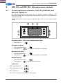
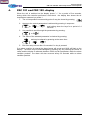
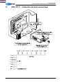
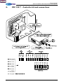
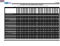
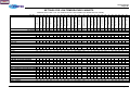
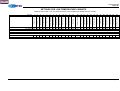
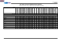
Back to top
Service manual
for the
FDC 121 and FDC 122
microprocessor control panels
UK trade spare parts and servicing
Menu
Service manual
FDC 121 and FDC 122 microprocessor control panels
Copyright
Copyright Foster Refrigerator (UK) Limited, November 2000
All rights reserved. No part of this publication may be reproduced, stored in a retrieval system, or
transmitted in any form or by any means, electronic, mechanical, photocopying, recording or
otherwise, without the prior permission of Foster Refrigerator (UK) Limited.
Foster Refrigerator (UK) Limited
Oldmedow Road
KING'S LYNN
PE30 4JU
United Kingdom
Tel: +44 (0) 1553 691122
Fax: +44 (0) 1553 691447
Web: www.fosterrefrigerator.co.uk
November 2000
Page ii
Menu
Service manual
FDC 121 and FDC 122 microprocessor control panels
Safety of personnel
Liability
Foster Refrigerator (UK) Limited decline responsibility when an attempt is made to use the
refrigerator for any purpose other than that for which it was designed.
WARNING!
THOSE WHO MAINTAIN THE REFRIGERATOR MUST BE TRAINED
IN STANDARD REPAIR AND MAINTENANCE PRACTICES AND
MUST
HAVE
READ
AND
UNDERSTOOD
THE
SAFETY
INSTRUCTIONS CONTAINED IN THIS MANUAL BEFORE
CARRYING OUT ANY MAINTENANCE.
Operating environment
Temperature
The Refrigerator must be used in a clean, well-lit environment with a stable temperature of
approximately 5°C to 35°C.
Relative humidity
The Refrigerator must be used in an environment with a relative humidity between 20% to 80%
(non-condensing).
Symbols and decals
Personnel must be familiar with all the warning symbols and decals fitted to the Refrigerator.
Failure to recognise a warning and read the associated safety instructions may result in injury or
death.
THIS DECAL IS USED TO INDICATE AN ELECTRICAL HAZARD.
THE REFRIGERATOR MUST BE DISCONNECTED FROM THE
MAINS ELECTRICAL POWER SUPPLY WHEN THIS DECAL IS
ENCOUNTERED DURING INSTALLATION AND MAINTENANCE.
Electrical hazard
WARNING!
THE REFRIGERATOR MUST BE DISCONNECTED FROM THE
MAINS ELECTRICAL POWER SUPPLY WHEN THIS DECAL IS
ENCOUNTERED DURING INSTALLATION, MAINTENANCE OR
SETTING-UP.
November 2000
Page iii
Menu
Service manual
FDC 121 and FDC 122 microprocessor control panels
Electro-static discharge (ESD)
CAUTION! Precautions against ESD must be taken to prevent damage to the Refrigerator
control circuits:
(1) Ensure that the operating environment is protected against ESD.
(2) Do not touch electronic circuits or wafers.
(3) Always use a grounded wrist strap while handling electronic circuits.
November 2000
Page iv
Menu
Service manual
FDC 121 and FDC 122 microprocessor control panels
1.
Electrical Connections
Replacing MCDU11/1 with CD121T1R0
•
Move live supply from MCD terminal 4 to CDC terminal 3
•
Move compressor output from MCD terminal 5 to CDC terminal 5
•
Move 12 V a.c. supply from MCD terminals 7 & 8 to CDC terminals 8 & 9
•
Move air probe wiresfrom MCD terminals 11 & 12 to CDC terminals 11 & 12
Replacing MCDU11/2 with CDC122T1R2
•
Remove link between MCD terminals 1 & 4
•
Move live supply from MCD terminal 1 to CDC terminal 3
•
Move defrost output from MCD terminal 2 to CDC terminal 4
•
Move compressor output from MCD terminal 5 to CDC terminal 5
•
Move fan output from MCD terminal 3 to CDC terminal 6
•
Move 12 V a.c. supply from MCD terminals 7 & 8 to CDC terminals 8 & 9
•
Move evaporator probe wires from MCD terminal 9 & 10 to CDC terminals 10 & 11
•
Move air probe wires from MCD terminals 11 & 12 to CDC terminals 11 & 12
November 2000
Page 1
Menu
Service manual
FDC 121 and FDC 122 microprocessor control panels
2.
FDC 121 and FDC 122 - microprocessor controls
2.1
The microprocessor controller - FDC 121 (15246141) and
FDC 122 (15246151)
All controller parameters are factory set for optimum storage conditions. The
parameters should only be adjusted by persons familiar with the unit operation and
controller functions.
Certain parameters however may be adjusted within limits, to suit certain storage
needs.
Check set point - Low point of temperature band.
•
Press button 1
Increase set point
•
Press and hold button 1
•
Press button 3
until required temperature is displayed.
Decrease set point
•
Press and hold button 1
•
Press button 4
until required temperature is displayed.
Manual defrost
•
Press and hold button 2
•
Press button 4
a timed defrost will follow.
Indicators
•
LED 5 Compressor on
•
LED 6 Evaporator Fan on
•
LED 7 Defrost on
•
PF1 or PF2: Indicates a probe failure - call engineer.
November 2000
Page 2
Menu
Service manual
FDC 121 and FDC 122 microprocessor control panels
Adjustment parameters
Refrigerator
+1/+5.
Factory setting
+1/+4
November 2000
Freezer
-25/-15
Meat/Chill
-3/+3
Fish
-1/+3
-18 to -21
-2 to +3
-1/+1
Page 3
Menu
Service manual
FDC 121 and FDC 122 microprocessor control panels
3.
FDC 121 and FDC 122 - thermostat function
3.1
Thermostat function - FDC 121 and FDC 122
•
SPL
Minimum set point (°C).
Maximum allowable low alarm setting (°C).
•
SPh
Maximum set point (°C).
Maximum allowable high alarm setting (°C).
•
hyS
Temperature hysteresis (°K).
•
coF
Compressor minimum off time (mins).
•
con
Compressor minimum on time (mins).
•
cdc
Cooler duty cycle. Compressor on duration during a ten minute cycle e.g. cdc
04, 4 min on time, 6 min off time (active only under probe fault conditions PF1).
•
crS
Compressor start delay (secs).
3.2
Defrost function
•
drE
Time between defrosts (hrs).
•
dLl
Defrosts termination temperature (°C).
•
dto
Defrost termination time (mins). Unused if set to zero.
•
drP
Drain down time (mins).
•
diS
Display during defrost:00
= Temperature display
-01
= dEF is displayed during defrost and until air temperature fails
below the value setpoint + hysteresis.
1..30 (mins)
•
•
dtY
doP
November 2000
=
dEF is displayed during defrost and until the set time
has elapsed after defrosting or until airtemperature fails
below the value setpoint + hysteresis.
Defrost Type
FAn
=
Off cycle defrost.
ELE
=
Electric heater defrost.
GAS
=
hot gas defrost.
Defrost Optimisation
con
=
At regular intervals of drE (hrs).
Acc
=
Defrost timer only runs while evaporator temperature is
below 0°C, defrosting occurs when drE time has elapsed
e.g. if compressor cycle time is 5 min run and 5 min stop
and drE = 4, defrosting will take place every 8 hours
approx.
Page 4
Menu
Service manual
FDC 121 and FDC 122 microprocessor control panels
3.3
•
Evaporator fan control
Fct
Evaporator fan control during cooling
-01
=
continuous operation.
00
=
cycle on/off with compressor.
1..00 (mins)
=
start with compressor,
compressor.
•
Frs
Fan delay temperature following defrost (°C)
•
Fid
Evaporator fan operation during defrost:-
3.4
time
delay
stop
after
00
= off until fan delay temperature FrS (°C) is reached.
01
= on while evaporator temperature is below valve FrS (°C).
02
= on during defrost.
Alarm function
•
Alo
Low temperature alarm setting (°C).
•
Ahl
High temperature alarm setting (°C).
•
AdL
Alarm delay (min),
•
set
Ain
3.5
00
= instantaneous audible alarm.
01..120
= duration of delay (min).
-01
= alarm is disabled.
Determines which probe is monitored for alarm functions:1
= air probe (probe 1).
2
= evaporator probe (probe 2).
3
= food probe (probe 3)
Thermal mass simulation
•
oSi
Thermostat (Air probe) offset (°K).
•
oS2
Evaporator probe offset (°K).
•
oS3
Display offset (°K). - where fitted.
•
SIM
Controls the thermal mass volume simulated by the controller and displayed on
the fascia. The greater the value the greater the resulting display slow down.
The controlling function remains to operate directly on air temperature.
•
Adr
November 2000
00
= instantaneous in temperature display.
01..200
= thermal mass simulation.
Controller peripheral number - only used where controllers are networked.
Page 5
Menu
Service manual
FDC 121 and FDC 122 microprocessor control panels
4.
FDC 121 and FDC 122 -display
When the unit is switched on the display shows "---" for a period of five seconds,
during which the controller perforems a self-check. the display then shows the air
temperature measure byu probe 1.
1.
The coil temperature measured by probe 2 may be viewed by pressing
2.
Access to the control parameters is achieved by pressing in sequence:
+
3.
+
and holding down the keys for a period of 4
seconds.
It is possible to scroll through the parameters by pressing:
or
4.
The value of the selected parameter is checked by pressing:
and may be altered by pressing at the same time:
5.
Exit from setup occurs after 10 seconds if no key is pressed.
If an alarm condition is entered the alarm buzzer will sound and 'ALM' will flash on the
display. The alarm may be acknowledged by pressing any key causing the buzzer to
cease and the display to alternate between 'ALM' and air temperature while the alarm
condition persists. the alarm will also re-sound efvery 30 seconds while an alarm
condition persists.
November 2000
Page 6
Menu
Service manual
FDC 121 and FDC 122 microprocessor control panels
5.
FDC 121 T – Controller kit and connections
November 2000
Page 7
Menu
Service manual
FDC 121 and FDC 122 microprocessor control panels
6.
FDC 122 T – Controller kit and connections
November 2000
Page 8
Menu
Service manual
<range-id>
SETTINGS FOR LOW TEMPERATURE CABINETS
CONTROLLER FITTED:- FDC 122 COMPLETE WITH TWO PROBES (AIR PROBE & EVAP. PROBE)
00
00
00
00
00
00
00
00
00
00
00
00
00
00
00
6
6
6
6
6
6
6
6
6
6
6
6
6
6
6
November 2000
-15
-15
-15
-15
-15
-15
-15
2
2
2
2
3
3
3
3
3
3
3
3
3
3
3
2
2
2
2
2
2
2
2
20
21
22
23
24
25
26
DO NOT CHANGE
00
00
00
00
00
00
00
00
00
00
00
00
00
00
00
-21
-21
-21
-21
-21
-21
-21
-3
-3
-3
-3
00
00
00
00
19
Thermal mass
simulation
PS 110 LU,
PS 220 LU,
PS 400 LU,
PS 900 LU,
PS 500 LT, PS 600 LT,
PS 1130 LT, PS 1350 LT,
PS 2901290 HLT (LOW),
PS 220 MU.
PS 400 MU, PS 900 MU,
PS 500 MT. PS 600 MT,
PS 1130 MT, PS 1350 MT,
PS 220 CU
PS 400 CU, PS 900 CU,
PS 500 CT, PS 600 CT,
PS 1130 CT, PS 1350 CT,
18
Display Offset
6
6
6
6
6
6
6
6
6
6
6
6
6
17
Evap probe offset
Disp. during defrost
00
00
00
00
00
00
00
00
00
00
00
00
00
16
Air probe offset
Drain down time
00
00
00
00
00
00
00
00
00
00
00
00
00
15
Air probe
Defrost duration
coF con cdc crs drE dLl dto drP diS
00 00
6
00
6
30 20
3
00
14
Alarm delay
Defrost end temp
Mnemonic SPL SPH hYS
Std. Setting -23 -15 3
GASTRO PRO CABINETS PREFIXED WITH PRO 500 MT, 600MT,
-3
2
2
1130 MT, 1350 MT,
-3
2
2
1/1 M, 1/2M, 1/3M, 1/4. M
-3
2
2
2/1 M, 2/2M, 2/3M, 2/4, M
.3
2
2
500 MTR, 600 MTR,
-3
2
2
500 CT, 600CT,
00
3
2
1/30 CT, 1350 CT,
00
3
2
500 LT, 600 LT,
-23 -15 3
1130 LT, 1350 LT.
-23 -15 3
11/L, 1/2L, 1/3L, 1/4L,
-23 -15 3
2/1 L, 2/2L, 2/3L, 2/4L,
-23 -15 3
500 LTR, 600 LTR,
-23 -15 3
1130 LTR, 1350 LTR,
-23 -15 3
13
High alarm set
12
Low alarm set
11
Fan operation
10
Fan delay temp
9
Evap fan control
8
Defrost optimisation
7
Defrost type
6
Defrost interval
Temp hysteresis
5
Comp start delay
Max. Setpoint
4
Comp duty cycle at
PF
3
Comp min time on
2
Comp min time off
1
Min. Setpoint
Par. No.
dtY doP Fct FrS FiD ALo Ahi AdL Ain oS1 oS2 oS3 SiM Adr
ELE con -1 -5 00 -25 -10 60
1
00 00 00 00
1
00
6
30
5
2
00 GAS
00
6
30
5
2
00 GAS
00
6
30
5
2
00 GAS
00
6
30
5
2
00 GAS
00
6
10 10
2
00 ELE
00
6
30
5
2
00 GAS
00
6
30
5
2
00 GAS
00
6
30 10
3
00 GAS
00
6
30 10
3
00 GAS
00
6
30 10
3
00 GAS
00
6
30 10
3
00 GAS
00
6
25 15
3
00 ELE
00
6
25 15
3
00 ELE
PUBLIC SECTOR CABINETS
00
8
30 20
3
00 ELE
00
6
20
8
3
00 GAS
00
6
20 20
1
00 ELE
00
6
25 20
3
00 ELE
00
6
30
8
1
00 GAS
00
6
30
8
1
00 GAS
00
6
20 15
1
00 ELE
00
6
25
8
1
00 GAS
00
6
20 10
1
00 ELE
00
6
30
5
1
00 GAS
00
6
30
5
1
00 GAS
00
6
25
8
1
00 GAS
00
6
20 10
1
00 ELE
00
6
30
5
1
00 GAS
00
6
30
5
1
00 GAS
con
con
con
con
con
con
con
con
con
con
con
con
con
-1
-1
-1
-1
-1
-1
-1
-1
-1
-1
-1
-1
-1
-2
-2
-2
-2
-2
-2
-2
-5
-5
-5
-5
-5
-5
00
00
00
00
00
00
00
00
00
00
00
00
00
-3
-3
-3
-3
-3
-1
-1
-25
-25
-25
-25
-25
-25
5
5
5
5
5
8
8
-10
-10
-10
-10
-10
-10
60
60
60
60
60
60
60
60
60
60
60
60
60
1
1
1
1
1
1
1
1
1
1
1
1
1
00
00
00
00
00
00
00
00
00
00
00
00
00
00
00
00
00
00
00
00
00
00
00
00
00
00
00
00
00
00
00
00
00
00
00
00
00
00
00
00
00
00
00
00
00
00
00
00
00
00
00
00
1
1
1
1
1
1
1
1
1
1
1
1
1
con
con
con
con
con
con
con
con
con
con
con
con
con
con
con
-1
-1
-1
-1
-1
-1
-1
-1
-1
-1
-1
-1
-1
-1
-1
-5
-5
-5
-5
-5
-5
-5
-2
-2
-2
-2
-2
-2
-2
-2
00
00
00
00
00
00
00
00
00
00
00
00
00
00
00
-25
-25
-25
-25
-25
-25
-25
-3
-3
-3
-3
-3
-3
-3
-3
-10
-10
-10
-10
-10
-10
-10
5
5
5
5
5
5
5
5
60
60
60
60
60
60
60
60
60
60
60
60
60
60
60
1
1
1
1
1
1
1
1
1
1
1
1
1
1
1
00
00
00
00
00
00
00
00
00
00
00
00
00
00
00
00
00
00
00
00
00
00
00
00
00
00
00
00
00
00
00
00
00
00
00
00
00
00
00
00
00
00
00
00
00
00
00
00
00
00
00
00
00
00
00
00
00
00
00
00
1
1
1
1
1
1
1
1
1
1
1
1
1
1
1
Page 9
Menu
Service manual
<range-id>
SETTINGS FOR LOW TEMPERATURE CABINETS
CONTROLLER FITTED:- FDC 122 COMPLETE WITH TWO PROBES (AIR PROBE & EVAP. PROBE)
4
5
6
7
8
9
10
11
12
13
14
15
16
17
18
19
20
21
22
23
Max. Setpoint
Temp hysteresis
Comp min time off
Comp min time on
Comp duty cycle at
PF
Comp start delay
Defrost interval
Defrost end temp
Defrost duration
Drain down time
Disp. during defrost
Defrost type
Defrost optimisation
Evap fan control
Fan delay temp
Fan operation
Low alarm set
High alarm set
Alarm delay
Air probe
Air probe offset
Evap probe offset
Mnemonic SPL SPH hYS coF con cdc crs drE dLl dto drP diS dtY dxaoP Fct FrS FID ALo Ahi AdL Ain oS1 oS2
Std. Setting -23 -15 -3 00 00
6
00
6
30 20
3
00 ELE con -1 -5 00 -25 -10 60
1
00 00
MAXIMA CABINETS PREFIXED WITH 'LR'
400 ADU (G),
-23 -15 3
00 00
6
00
6
20 20
1
00 ELE con -1 -5 00 -25 -10 60
1
00 00
900 ADU,
-23 -15 3
00 00
6
00
6
25 20
1
00 ELE con -1 -5 00 -25 -10 60
1
00 00
110 U,
-23 -15 3
00 00
6
00
8
30 20
3
00 ELE con -1 -5 00 -25 -10 60
1
00 00
220 U,
-23 -15 3
00 00
6
00
6
20
8
3
00 GAS con -1 -5 00 -25 -10 60
1
00 00
PREFIXED WITH 'HR'
220 ADUMC,
-3
2
2
00 00
6
00
6
25
8
1
00 GAS con -1 -2 00 -3
5
60
1
00 00
110 ADUMC,
-3
2
2
00 00
6
00
8
7
20
3
00 ELE con -1 -2 00 -3
5
60
1
00 00
400 ADUMC, 900 ADUMC,
-3
2
2
00 00
6
00
6
20 10
1
00 ELE con -1 -2 00 -3
5
60
1
00 00
SOLO PLUS W & C MODELS 50 TO 200
M' RANGE,
-3 00
2
00 00
6
00
6
30
6
2
00 GAS con -1 -5 00 -3
5
60
1
00 00
C' RANGE,
-3 00
2
00 00
6
00
6
30
6
2
00 GAS con -1 -2 00 -3
5
60
1
00 00
L' RANGE (-21),
-23 -15 3
00 00
6
00
6
30 10
3
00 GAS con -1 -5 00 -25 -10 60
1
00 00
L' RANGE (-27),
-28 -15 2
00 00
6
00
6
30 12
3
00 GAS con -1 -5 00 -30 -10 60
1
00 00
COMPAKT 300 RANGE 410 TO 1010
L' MODELS,
-23 -15 3
00 00
6
00
6
20
8
2
00 GAS con -1 -5 00 -25 -10 60
1
00 00
M' MODELS,
-3
2
3
00 00
6
00
6
20
8
2
00 GAS con -1 -2 00 -3 -5 60
1
00 00
BAKERY STORAGE FREEZER CABINETS PREFIXED (C)BSH & HBF
20 ADT, 40 ADT,
-23 -15 3
00 00
6
00
6
30
8
1
00 GAS con -1 -5 00 -25 -10 60
1
00 00
34 ADT/2,
-25 -10 2
3
2
6
00
6
10 20
5
00 GAS con -1 -10 00 -28 -5 60
1
00 00
CBSF 34 ADT,
-23 -10 2
3
00
6
00 12 10 20
5
00 GAS con -1 -5 00 -25 -10 60
1
00 00
DOUGH RETARDER COUNTERS
DR 16 VE, DR 24 VE
-5
3
2
00 00
6
00
6
30
5
1
00 GAS con -1
0
00 -10 8
60
1
00 00
DR 20 VT, DR 40 VT
-5
3
2
00 00
6
00
6
25
8
1
00 GAS con -1 -2 00 -6
8
60
1
00 00
BAKERY FREEZER COUTNER & REMOTE
BSCF 16 ADE
-23 -15 3
00 00
6
00
6
15 12
1
00 ELE con -1 -5 00 -25 -10 60
1
00 00
BSCF 24 ADE
-23 -15 3
00 00 00 00
6
15 12
1
00 ELE con -1 -5 00 -25 -10 60
1
00 00
BAKERY FAST FREEZER
CBFF 34T/2, BFF 34T/2
-25 -15 3
00 00
6
00 12 25 25
5
00 ELE Con -1 -5 00 -35 -10 60
1
00 00
CBFF 34 RIT, BFF 34 RIT
-25 -15 3
00 00
6
00
6
10 45
5
00 ELE Acc -1 -5 00 -35 -10 60
1
00 00
November 2000
24
25
26
DO NOT CHANGE
3
Thermal mass
simulation
2
Display Offset
1
Min. Setpoint
Par. No.
oS3 SiM Adr
00 00
1
00
00
00
00
00
00
00
00
1
1
1
1
00
00
00
00
00
00
1
1
1
00
00
00
00
00
00
00
00
1
1
1
1
00
00
00
00
1
1
00
00
00
00
00
00
1
1
1
00
00
00
00
1
1
00
00
00
00
1
1
00
00
00
00
1
1
Page 10
Menu
Service manual
<range-id>
SETTINGS FOR LOW TEMPERATURE CABINETS
CONTROLLER FITTED:- FDC 122 COMPLETE WITH TWO PROBES (AIR PROBE & EVAP. PROBE)
20
21
22
23
24
25
26
DO NOT CHANGE
19
Thermal mass
simulation
-23 -15
18
Display Offset
November 2000
5
17
Evap probe offset
Disp. during defrost
S400-L & S600-L
0
16
Air probe offset
Drain down time
PMC 1-5, HFT, HRT
15
Air probe
Defrost duration
coF con cdc crs drE dLl dto drP diS
00 00
6
00
6
30 20
3
00
14
Alarm delay
Defrost end temp
Mnemonic SPL SPH hYS
Std. Setting -23 -15 -3
PATISSERIE FREEZER CABINETS
HBT 12T
-25 -10 2
HBT 34T
-25 -10 2
PATL 12T
-25 -10 2
PATISSERIE CABINETS
HSK 12T
00 10
2
PATH 12T
00 10
2
BAKOLINE FORCED AIR PATISSERIE FREEZER
HLF 64
-25 -10 2
HLF 6347
-25 -10 2
BAKOLINE STATIC COIL FREEZER
TGS 64
-25 -10 3
BAKOLINE FAST FREEZER
BHS 86
-25 -10 3
UNDER BOILER COUNTER
UBC 2/2 M
-3 -1
2
SLIMLINE STORAGE FREEZER
LR & LHR 125 ADU
-23 -15 3
LR & LHR 301 ADU
-23 -15 3
SERVICE MASTER CABINET
SMU 315
1
5
3
PREP COUNTER TOP DISPLAY SYSTEM
PC 1/2 ERTH
3
5
2
PC 1/2 ADMERTH
3
5
2
PC 1/2 ADERTH
3
5
2
13
High alarm set
12
Low alarm set
11
Fan operation
10
Fan delay temp
9
Evap fan control
8
Defrost optimisation
7
Defrost type
6
Defrost interval
Temp hysteresis
5
Comp start delay
Max. Setpoint
4
Comp duty cycle at
PF
3
Comp min time on
2
Comp min time off
1
Min. Setpoint
Par. No.
dtY dxaoP Fct FrS FiD ALo Ahi AdL Ain oS1 oS2 oS3 SiM Adr
ELE con -1 -5 00 -25 -10 60
1
00 00 00 00
1
3
3
3
2
2
00
6
6
6
00
00
00
12
12
8
20
20
30
20
20
20
5
5
5
00
00
5
GAS
GAS
GAS
con
con
con
-1
-1
-1
-5
-10
-5
00
00
00
-28 -5
-28 -5
-25 -10
60
60
60
1
1
1
00
00
00
00
00
00
00
00
00
00
00
00
1
1
1
3
3
2
00
6
6
00
00
12
12
10
10
30
30
1
1
00
00
FAN
ELE
con
con
-1
-1
5
00
2
00
-1
00
12
8
60
60
1
1
00
00
00
00
00
00
00
00
1
1
3
3
2
2
6
6
00
00
12
12
10
10
20
40
5
5
00
00
GAS
ELE
con
con
-1
-1
-5
-10
00
00
-28 -5
-28 -10
60
60
1
1
00
00
00
00
00
00
00
00
1
1
3
2
6
00
12
10
20
5
00
GAS
con
-1
-5
00
-28
10 120
1
00
00
00
00
1
3
2
6
00
12
10
45
5
00
GAS
con
-1
-10
00
-35
-5
60
1
00
00
00
00
1
00
00
6
00
6
30
5
1
00
GAS
con
-1
0
00
-3
5
60
1
00
00
00
00
1
00
00
00
00
6
6
00
00
6
6
25
15
10
8
1
1
00
00
GAS
ELE
con
con
-1
-1
-5
-5
00
00
-25 -10
-25 -10
60
60
1
1
00
00
00
00
00
00
00
00
1
1
00
00
6
00
6
30
8
1
00
GAS
con
-1
16
00
00
10
60
1
4
00
4
00
1
00
00
00
00
00
00
6
6
6
00
00
00
6
6
6
15
15
15
8
8
8
1
1
1
00
00
00
GAS
GAS
GAS
con
con
con
-1
-1
-1
00
00
00
00
00
00
2
2
2
10
10
10
60
60
60
1
1
1
00
00
00
00
00
00
00
00
00
00
00
00
1
1
1
3
00
00
6
00
6
30
15
1
00
GAS
con
-1
1
00
0
10
60
1
00
00
00
00
1
3
00
00
6
00
6
20
20
2
00
ELE
con
-1
-5
00
-25 -10
60
1
00
00
00
00
1
Page 11
Menu
Service manual
<range-id>
SETTINGS FOR LOW TEMPERATURE CABINETS
CONTROLLER FITTED:- FDC 122 COMPLETE WITH TWO PROBES (AIR PROBE & EVAP. PROBE)
19
22
23
Evap probe offset
21
Air probe offset
High alarm set
20
24
25
26
DO NOT CHANGE
18
Thermal mass
simulation
17
Display Offset
16
Air probe
15
Alarm delay
14
Low alarm set
Disp. during defrost
13
Fan operation
12
Fan delay temp
11
Evap fan control
10
Defrost optimisation
9
Defrost type
8
Drain down time
Comp min time off
7
Defrost duration
Temp hysteresis
November 2000
6
Defrost end temp
Max. Setpoint
Mnemonic SPL SPH hYS coF
Std. Setting -23 -15 -3 00
ICE CREAM FREEZER CABINET WITH GLASS DOOR
ICF 450 ADUG
-28 -20 2
00
LOCKHART ARTIC CABINETS & COUNTERS
HE 3223, HE 3224
-23 -15 3
00
5
Defrost interval
4
Comp start delay
3
Comp duty cycle at
PF
2
Comp min time on
1
Min. Setpoint
Par. No.
con cdc crs drE dLl dto drP diS
00
6
00
6
30 20
3
00
dtY dxaoP Fct FrS FID ALo Ahi AdL Ain oS1 oS2 oS3 SiM Adr
ELE con -1 -5 00 -25 -10 60
1
00 00 00 00
1
00
6
00
6
15
15
3
00
ELE
CON
-1
-5
00
20
-30
60
1
00
00
00
00
1
00
5
00
6
30
8
1
5
GAS CON
-1
-5
00
-25 -15
60
1
00
00
00
00
1
Page 12
Menu
Service manual
<range-id>
SETTINGS FOR LOW TEMPERATURE CABINETS
CONTROLLER FITTED:- FDC 121 COMPLETE WITH ONE PROBES (AIR PROBE)
Comp min time off
Comp min time on
Comp duty cycle at
PF
Comp Start delay
Defrost interval
Defrost end temp
Defrost duration
Drain down time
Disp. during defrost
November 2000
15
16
17
18
19
20
21
22
23
24
25
dtY
FAN
doP
con
Fct FrS FiD ALo Ahi AdL Ain oS1 oS2 oS3 SiM
-1 -5
2
00 10 30
1
00 00 00 00
26
DO NOT CHANGE
Temp hysteresis
S400-H & S600-H
2
5
2
00 00
6
00
6
ALL CABINETS WITH PREFIX OF PRO
500 HT-G, 600HT-G
3
8
2
00 00
6
00
6
1130HT-G, 1350HT-G
3
8
2
00 00
6
00
6
500HTR-Q 600HTR-G
3
8
2
00 00
6
00
6
1130HTR-Q 1350HTR-G
3
8
2
00 00
6
00
6
1/1H, 1/2H, 1/3H, 1/4H
3
8
2
00 00
6
00
6
2/1H, 2/2H, 2/3H, 2/4H
3
8
2
00 00
6
00
6
500WTG, 600WTG
5
17
2
00 00
6
00
6
MAXIMA CABINETS PREFIX HR
110U, 220U, 400U, 90OU
2
-5
2
00 00
6
00
6
400UG, 900UG
2
5
2
00
6
00
6
220UF, 400UF
-1
1
2
00 00
6
00 12
400UWG
5
17
2
00 00
6
00
6
SLIMLINE STORAGE CABINET
HR125U
2
5
2
00 00
6
00
6
BARMASTERS
2EA/D, 3EA/D, 4EA/D
6
10
4
00 00
6
00
6
DUET SPLIT SYSTEMS
ALL H MODELS
1
10
3
00 00
6
00
6
COMPAKT 300 RANGE - 410' T0 '1010'
ALL H MODELS
1
5
2
00 00
6
00
6
PUBLIC SECTOR PREFIXED WITH 'PS'
ALL 'H' MODELS
1
5
3
00 00
6
00
6
SOLO PLUS MODELS CEILING & WALL MOUNT – '50' TO '200'
ALL 'H' MODELS
1
5
3
00 00
6
00
6
ALL WINE MODELS
5
17
2
00 00
6
00
6
LOCKHART ARTICA CABINET & COUNTER RANGE PREFIXED WITH 'HE'
3221, 3222, 3225, 3226
3
8
2
00 00
6
00
6
14
Thermal mass
simulation
Max. Setpoint
Mnemonic SPL SPH hYS coF con cdc crs drE dLl dto drP diS
Std. Setting 1
5
3
00 00
6
00
6
30 15
1
00
13
Display Offset
12
Evap probe offset
11
Air probe offset
10
Air probe
9
Alarm delay
8
High alarm set
7
Low alarm set
6
Fan operation
5
Fan delay temp
4
Evap fan control
3
Defrost optimisation
2
Defrost type
1
Min. Setpoint
Par. No.
Adr
1
30
15
1
00
FAN
con
-1
-5
2
00
10
30
1
00
00
00
00
1
30
30
30
30
30
30
30
15
15
15
15
15
15
5
1
1
1
1
1
1
1
00
00
00
00
00
00
00
FAN
FAN
FAN
FAN
FAN
FAN
FAN
con
con
con
con
con
con
con
-1
-1
-1
-1
-1
-1
-1
-5
-5
-5
-5
-5
-5
-5
2
2
2
2
2
2
2
00
00
00
00
00
00
4
10
10
10
10
10
10
20
30
30
30
30
30
30
30
1
1
1
1
1
1
1
00
00
00
00
00
00
00
00
00
00
00
00
00
00
00
00
00
00
00
00
00
00
00
00.
00
00
00
00
1
1
1
1
1
1
1
30
30
30
30
15
15
15
5
1
1
1
1
00
00
00
00
FAN
FAN
FAN
FAN
con
con
con
con
-1
-1
-1
-1
-5
-5
-5
-5
2
2
2
2
00
00
-3
4
10
10
5
20
30
30
90
30
1
1
1
1
00
00
00
00
00
00
00
00
00
00
00
00
00
00
00
00
1
1
1
1
30
15
1
00
FAN
con
-1
-5
2
00
10
30
1
00
00
00
00
1
30
15
1
00
FAN
con
-1
-5
2
4
16
30
1
00
00
00
00
1
30
15
1
00
FAN
con
-1
-5
2
-2
12
60
1
00
00
00
00
1
30
15
1
00
FAN
con
-1
-5
2
00
10
60
1
00
00
00
00
1
30
15
1
00
FAN
con
-1
-5
2
00
10
30
1
00
00
00
00
1
30
30
15
5
1
1
00
00
FAN
FAN
con
con
-1
-1
-5
-5
2
2
00
4
10
20
30
30
1
1
00
00
00
00
00
00
00
00
1
1
30
15
1
00
FAN
con
-1
-5
2
00
10
30
1
00
00
00
00
1
Page 13
Menu
Service manual
<range-id>
SETTINGS FOR HIGH TEMPERATURE CABINETS
CONTROLLER FITTED:- FDC 121 COMPLETE WITH ONE PROBES (AIR PROBE)
Comp min time off
Comp min time on
Comp duty cycle at
PF
Comp start delay
Defrost interval
Defrost end temp
Defrost duration
Drain down time
Disp. during defrost
15
16
17
18
19
20
21
22
23
24
25
dtY dxaoP Fct FrS FID ALo Ahi AdL Ain OS1 oS2 oS3 SiM
FAN con -1 -5
2
00 10 30
1
00 00 00 00
26
DO NOT CHANGE
Temp hysteresis
PIZZA HUT CABINETS
PTPR RI 1T (PROVE)
PRPT-RI-1T (THAW/RET)
PIZZA HUT MAKE TABLE COUNTER
PM-3ERT
ROLL IN CABINETS
R160 1T
R160 1T/G
R1135 1T
MRI-1-H(P), MRI-2-H(P)
SHOP LINE CABINET
SL 46 S
14
Thermal mass
simulation
Max. Setpoint
Mnemonic SPL SPH hYS coF con cdc crs drE dLl dto drP diS
Std. Setting 1
5
3
00 00
6
00
6
30 15
1
00
13
Display Offset
12
Evap probe offset
11
Air probe offset
10
Air probe
9
Alarm delay
8
High alarm set
7
Low alarm set
6
Fan operation
5
Fan delay temp
4
Evap fan control
3
Defrost optimisation
2
Defrost type
1
Min. Setpoint
Par. No.
Adr
1
28
2
35
4
4
3
00
00
00
00
6
6
00
00
24
24
30
30
1
1
1
1
00
00
FAN
FAN
con
con
-1
-1
-5
-5
2
2
-1
-1
45
45
30
30
1
1
00
00
00
00
00
00
00
00
1
1
3
5
2
00
00
6
00
6
30
15
1
00
FAN
con
-1
-5
2
00
10
30
1
00
00
00
00
1
1
1
1
1
5
5
5
5
3
3
3
3
00
00
00
00
00
00
00
00
6
6
6
6
00
00
00
00
6
6
6
6
30
30
30
30
15
15
15
15
1
1
1
1
00
00
00
00
FAN
FAN
FAN
FAN
con
con
con
con
-1
-1
-1
-1
-5
-5
-5
-5
2
2
2
2
00
00
00
00
10
10
10
10
30
30
30
30
1
1
1
1
00
00
00
00
00
00
00
00
00
00
00
00
00
00
00
00
1
1
1
1
0
10
2
3
2
6
00
12
10
30
1
00
FAN
con
-1
5
2
-1
12
60
1
00
00
00
00
1
1
1
1
5
5
5
3
3
3
00
00
00
00
00
00
6
6
6
00
00
00
6
6
6
30
30
30
15
15
15
5
5
5
00
00
00
FAN
FAN
FAN
con
con
con
-1
-1
-1
-5
-5
-5
2
2
2
00
00
00
10
10
10
60
60
60
1
1
1
00
00
00
00
00
00
00
00
00
00
00
00
1
1
1
BAKERY CABINET
HSK 34 T
BSR 20 T
BSR 40 T
November 2000
Page 14