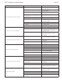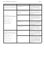
1
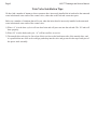
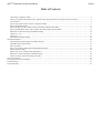
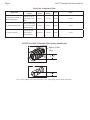
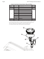
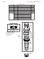
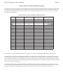
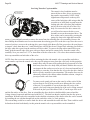
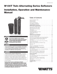
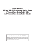
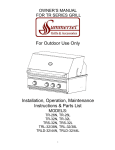
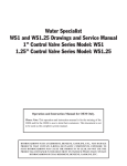
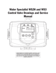
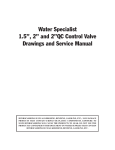
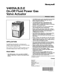
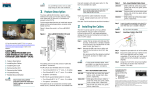
Water Specialist
WS1TT Drawings and Service Manual
2nd Tank
Connection
Port
Treated
Water
Outlet
Untreated
Water
Inlet
In/Out Head
2nd Tank
Connection
Port
Control
Valve
Proper installation shown above.
See page 2 for issues that arise if the in/out head is incorrectly connected to the
untreated water inlet/treated water outlet of the control valve, rather than to the 2nd tank connection ports.
HYDROCARBONS SUCH AS KEROSENE, BENZENE, GASOLINE, ETC., MAY DAMAGE
PRODUCTS THAT CONTAIN O-RINGS OR PLASTIC COMPONENTS. EXPOSURE TO
SUCH HYDROCARBONS MAY CAUSE THE PRODUCTS TO LEAK. DO NOT USE THE
PRODUCT(S) CONTAINED IN THIS DOCUMENT ON WATER SUPPLIES THAT CONTAIN
HYDROCARBONS SUCH AS KEROSENE, BENZENE, GASOLINE, ETC.
Page 2
WS1TT Drawings and Service Manual
Twin Valve Installation Tips:
We have had a number of instances where customers have incorrectly installed the in/out head to the untreated
water inlet/treated water outlet of the control valve, rather than to the 2nd tank connection ports.
Below are a number of situations that will occur when the in/out head is incorrectly installed to the untreated
water inlet/treated water outlet of the control valve.
1) When “A” is in the draw cycle it will not draw brine and will put water into the salt tank. The “B” tank will
draw properly.
2) When “B” is in the backwash cycle, “A” will have no flow to service.
3) The transfer disc seals may be forced out of their cavities on the back/motor side of the transfer discs, and
it is possible that one of the seals could get pushed up into the valve and get stuck in the top of tank port of
the spacer stack assembly.
WS1TT Drawings and Service Manual
Page 3
Table of Contents
Valve Body Compliance Table ................................................................................................................................................... 4
Drive Cap Assembly, Downflow Piston, Upflow Piston, Regenerant Piston and Spacer Stack Assembly ................................ 5
Twin Transfer .............................................................................................................................................................................. 6
Injector Cap, Injector Screen, Injector, Plug and O-Ring ........................................................................................................... 8
Injector Order Information ......................................................................................................................................................... 9
Injector Graphs US Units: Injector Draw, Slow Rinse and Total Flow Rates .......................................................................... 10
Injector Graphs Metric Units: Injector Draw, Slow Rinse and Total Flow Rates..................................................................... 12
Refill Flow Control Assembly and Refill Port Plug.................................................................................................................. 14
Drain Line – 3/4” ...................................................................................................................................................................... 15
Drain Line – 1” ......................................................................................................................................................................... 16
Interconnect Fitting Assembly .................................................................................................................................................. 19
General Information ......................................................................................................................................................................... 20
General Warnings (Must appear in OEM’s manual) ................................................................................................................ 20
Quick Reference Specifications ................................................................................................................................................ 22
Drive Assembly ........................................................................................................................................................................ 23
Drive Cap Assembly, Main Piston and Regenerant Piston ....................................................................................................... 24
Spacer Stack Assembly ............................................................................................................................................................. 24
Injector Cap, Screen, Injector Plug and Injector....................................................................................................................... 24
Refill Flow Control Assembly or Refill Port Plug .................................................................................................................... 24
Drain Line Flow Control and Fitting Assembly ....................................................................................................................... 25
Service Instructions.......................................................................................................................................................................... 26
Servicing Transfer Cap Assemblies ................................................................................................................................................. 30
Troubleshooting ............................................................................................................................................................................... 32
Limited Warranty ............................................................................................................................................................................. 36
Page 4
WS1TT Drawings and Service Manual
Valve Body Compliance Table
Injector and/or
Plug(s)
Main
Piston
Regenerant
Piston
Stack
Body*
1” Downflow Softener or
Regenerating Filter
Injector in “DN”
hole, Plug in “UP”
hole
V3011
V3174
V3005
V3031
1” Backwash Only Filter
Plug in “DN” and
“UP” holes, Install
Refill Port Plug
V3011
None
V3005
V3031
1” Upflow Softener
Injector in “UP”
hole, Plug in
unlabeled hole
V3011-01
V3174
V3005
V3031
Application
WS1TT with 1.050" Distributor Tube Opening Identification
Spacer Color:
Grey
1.25"
D
1.25"
Note: The downflow piston is a solid amber color. The upflow piston is black and amber.
WS1TT Drawings and Service Manual
Page 5
Drive Cap Assembly, Downflow Piston, Upflow Piston, Regenerant Piston and Spacer Stack Assembly
Drawing No.
1
2
3a
3b
4
5
Order No.
V3005
V3004
V3011*
V3011-01*
V3174
V3135
Description
WS1 Spacer Stack Assembly
Drive Cap ASY
WS1 Piston Downflow ASY
WS1 Piston Upflow ASY
WS1 Regenerant Piston
O-ring 228
Quantity
1
1
1
1
1
*V3011 is labeled with DN and V3011-01 is labeled with UP. Upflow option is not
applicable to EA, EE or EI control valves.
Note: The regenerant piston is not used in backwash only applications.
Refer to programming and Cover Drawing Manual
1
3b
2
4
3a
5
1
2
3
4
5
6
8
9
7
10
Twin Transfer
5
6
14
11
4
10
13
12
15
18
19
7
2
1
16
20
17
21
22
Page 6
WS1TT Drawings and Service Manual
Order No.
V3470
V3724
V4005-01
V4029
V4015
V4014
V4036
V3105
V3180
V4016
V3031
V4023
V3287
V4006-01
V4011-01
V4012
V4013
V3264
V3110
V3262-01
V3592
V4049
V4043
V3151
V4055*
V4017-01
D1400
Description
SCREW BHC 1/4-20 X 1 SS
WASHER FLAT SS 1/4
T1 TRANSFER CAP ASY
O-RING 236
T1 TRANSFER SPRING
T1 TRANSFER SPRING SUPPORT
T1 ROTOR DISK ASY
O-RING 215 (DISTRIBUTOR TUBE)
O-RING 337
T1 TRANSFER SEAL
T1 BODY SFT WTR REGEN
T1 TRANSFER DRIVE SHAFT ASY
O-RING 110
T1 TRANSFER DRIVE CAP ASY
T1 TRANSFER DRIVE GEAR ASY
T1 TRANSFER DRIVE GEAR AXLE
T1 TRANSFER REDUCTION GEAR
WS2H BYPASS REDUCTION GEARAXLE
WS1 DRIVE REDUCING GEAR 12X36
WS1.5&2ALT/2BY REDUCGEARCVRASY
SCREW #8-1 PHPN T-25 SS
T1 COVER ASSEMBLY
T1 TRANSFER MOTOR ASY
WS1 NUT 1 QC
TWIN TANK METER ASY
T1 INTERCONNECT FITTING ASY
1191 IN/OUT HEAD
Quantity
12
12
1
2
2
2
2
1
1
6
1
1
2
1
1
1
1
3
3
1
3
1
1
1
1
1
1
*THIS WATER METER SHOULD NOT BE USED AS THE PRIMARY MONITORING DEVICE FOR
CRITICAL OR HEALTH EFFECT APPLICATIONS.
Drawing No.
1
2
3
4
5
6
7
8
9
10
11
12
13
14
15
16
17
18
19
20
21
22
NOT SHOWN
NOT SHOWN
NOT SHOWN
NOT SHOWN
NOT SHOWN
Twin Transfer
WS1TT Drawings and Service Manual
Page 7
Page 8
WS1TT Drawings and Service Manual
Injector Cap, Injector Screen, Injector, Plug and O-Ring
Drawing No.
1
2
3
4
5
Not Shown
Not Shown
Order No.
V3176
V3152
V3177-01
V3010-1Z
V3010-1A
V3010-1B
V3010-1C
V3010-1D
V3010-1E
V3010-1F
V3010-1G
V3010-1H
V3010-1I
V3010-1J
V3010-1K
V3170
V3171
Description
INJECTOR CAP
O-RING 135
INJECTOR SCREEN CAGE
WS1 INJECTOR ASY Z PLUG
WS1 INJECTOR ASY A BLACK
WS1 INJECTOR ASY B BROWN
WS1 INJECTOR ASY C VIOLET
WS1 INJECTOR ASY D RED
WS1 INJECTOR ASY E WHITE
WS1 INJECTOR ASY F BLUE
WS1 INJECTOR ASY G YELLOW
WS1 INJECTOR ASY H GREEN
WS1 INJECTOR ASY I ORANGE
WS1 INJECTOR ASY J LIGHT BLUE
WS1 INJECTOR ASY K LIGHT GREEN
O-RING 011
O-RING 013
Quantity
1
1
1
1
1
*
*
* The injector plug and the injector each contain one 011 (lower) and 013 (upper) o-ring.
Note: For upflow position, injector is located in the up hole and injector plug is in the
other hole. Upflow option is not applicable to EA, EE or EI control valves.
For a filter that only backwashes, injector plugs are located in both holes.
1
2
4
3
5
WS1TT Drawings and Service Manual
Page 9
Injector Order Information
Typical Tank Diameter
Down
Up*
Injector Order Number
Injector Color
WS1 & WS1.25
V3010-1A
V3010-1B
V3010-1C
V3010-1D
V3010-1E
V3010-1F
V3010-1G
V3010-1H
V3010-1I
V3010-1J
V3010-1K
Black
Brown
Violet
Red
White
Blue
Yellow
Green
Orange
Light Blue
Light Green
6"
7"
8"
9"
10"
12"
13"
14"
16"
18"
21"
8"
9"
10"
12"
13"
14"
16"
18"
21"
Actual tank size used may vary depending on the design and application of the system.
Tank diameter is an approximation for the following:
1. downflow softener using standard mesh synthetic cation exchange media regenerating
with sodium chloride.
2. upflow softener using standard mesh synthetic cation exchange media regenerating
with sodium chloride, an inlet water pressure of 30 to 50 psi (2.1 to 3.4 bar) and water
temperature of 60°F (15.6°C) water or warmer. Higher pressures or lower temperatures
would need smaller injectors to avoid lifting the bed.
*Not applicable for EA, EE or EI control valves.
Page 10
WS1TT Drawings and Service Manual
WS1TT Drawings and Service Manual
Page 11
Page 12
WS1TT Drawings and Service Manual
WS1TT Drawings and Service Manual
Page 13
Page 14
WS1TT Drawings and Service Manual
Refill Flow Control Assembly and Refill Port Plug
Drawing No.
Order No.
1
V3195-01
Description
Quantity
This part is required for backwash only
systems
1
1
1
1
1
1
1
1
Option
Option
WS1 Refill Port Plug Asy
2
H4615
Elbow Locking Clip
3
JCP-P-6
Polytube insert 3/8”
4
JCPG-6PBLK Nut 3/8”
5
H4613
Elbow Cap 3/8”
6
V3163
0-ring 019
7
V3165-01*
WS1 RFC Retainer Asy (0.5 gpm)
8
V3182
WS1 RFC
9
V3330-01
WS1 Brine Elbow Asy w/RFC 3/8"
Not Shown
V3552
WS1 Brine Elbow Asy w/RFC 1/2"
Not Shown
H4650
Elbow ½” with nut and insert
*Assembly includes V3182 WS1 (0.5 gpm) RFC.
9
4
5
3
1
6
7
8
2
Water
Flow
Proper RFC orientation
directs refill water flow
towards the washer face
with rounded edge and text.
WS1TT Drawings and Service Manual
Page 15
Drain Line – 3/4”
Drawing No.
1
2
3
4*
5
6*
7
Order No.
H4615
PKP10TS8-BULK
V3192
V3158-01
V3163
V3159-01
V3162-007
V3162-010
V3162-013
V3162-017
V3162-022
V3162-027
V3162-032
V3162-042
V3162-053
V3162-065
V3162-075
V3162-090
V3162-100
Description
Elbow Locking Clip
Polytube insert 5/8
WS1 Nut ¾ Drain Elbow
WS1 Drain Elbow ¾ Male
O-ring 019
WS1 DLFC Retainer ASY
WS1 DLFC 0.7 gpm for ¾
WS1 DLFC 1.0 gpm for ¾
WS1 DLFC 1.3 gpm for ¾
WS1 DLFC 1.7 gpm for ¾
WS1 DLFC 2.2 gpm for ¾
WS1 DLFC 2.7 gpm for ¾
WS1 DLFC 3.2 gpm for ¾
WS1 DLFC 4.2 gpm for ¾
WS1 DLFC 5.3 gpm for ¾
WS1 DLFC 6.5 gpm for ¾
WS1 DLFC 7.5 gpm for ¾
WS1 DLFC 9.0 gpm for ¾
WS1 DLFC 10.0 gpm for ¾
Quantity
1
Option
Option
1
1
1
One
DLFC
must be
used if ¾
fitting is
used
*4 and 6 can be ordered as a complete assembly - V3331 WS1 Drain Elbow and Retainer Asy
Valves are shipped without drain line flow control (DLFC) - install DLFC before using. Valves
are shipped without ¾ nut for drain elbow (polytube installation only) and 5/8" polytube insert
(polytube installation only).
2
3
5
4
6
7
Water
Flow
Proper DLFC orientation
directs water flow towards
the washer face with
rounded edge.
1
Page 16
WS1TT Drawings and Service Manual
Drain Line - 1”
Drawing No.
1
2
3*
4*
5*
6*
7*
8*
Order No.
Description
Quantity
H4615
Elbow Locking Clip
1
V3008-02 WS1 Drain FTG 1 Straight
1
V3166
WS1 Drain FTG Body 1
1
V3167
WS1 Drain FTG Adapter 1
1
V3163
0-ring 019
1
V3150
WS1 Split Ring
1
V3151
WS1 Nut 1” QC
1
V3105
O-ring 215
1
V3190-090 WS1 DLFC 9.0 gpm for 1
One
V3190-100 WS1 DLFC 10.0 gpm for 1
DLFC
V3190-110 WS1 DLFC 11.0 gpm for 1
must be
V3190-130 WS1 DLFC 13.0 gpm for 1
9
V3190-150 WS1 DLFC 15.0 gpm for 1
used if 1”
V3190-170 WS1 DLFC 17.0 gpm for 1
fitting is
V3190-200 WS1 DLFC 20.0 gpm for 1
used
V3190-250 WS1 DLFC 25.0 gpm for 1
* Can be ordered as a set. Order number V3008-02, description: WS1 Drain FTG 1 Straight.
3
Water
Flow
Proper DLFC orientation
directs water flow towards
the washer face with
rounded edge.
9
8
6
2
7
4
5
1
WS1TT Drawings and Service Manual
Page 17
V4017-01 TT Interconnect Fitting Assembly up to 10” tanks
1
4
2
3
Drawing No.
1
2
3
4
Order No.
V3151
V3150
V3105
V4017
Description
WS1 NUT 1" QUICK CONNECT
WS1 SPLIT RING
O-RING 215
T1 INTERCONNECT FITTING
Quantity
4
4
4
2
V4052-01 TT Interconnect Fitting Assembly for 12” to 21” Tanks
4
1
3
5
cut to
length
5
4
1
2
3
2
Drawing No.
1
2
3
4
5
Order No.
V3151
V3150
V3105
V3352
V4052
Description
WS1 NUT 1” QUICK CONNECT
WS1 SPLIT RING
O-RING 215
WS1 FITTING 1¼”&1½” PVC SOLVENT
PIPE PVC SCH 80 1¼” X 2”
Quantity
4
4
4
4
2
D1400 1191 In/Out Head
Fitting Installation Instructions:
• Installation fittings are designed
to accommodate minor plumbing
misalignments, but are not designed to
support the weight of a system or the
plumbing.
• Slide nut on first, then the split ring and
o-ring.
• Hand tighten the nut only.
The V4017-01 twin tank control valve
interconnect kit can be used on tanks up
to 10” in diameter and is packed in with
control valve. If using 12” diameter
tanks or larger order optional kit
number V4052-01 twin tank control
valve interconnect kit for 12” thru 21”
diameter tanks.
1
2
Drawing No.
1
2
Order No.
V3180
V3105
Description
Quantity
O-RING 337
1
O-RING 215 (DISTRIBUTOR TUBE)
1
Page 18
WS1TT Drawings and Service Manual
Introduction
This manual is about a control valve to be used on water softeners or water filters. The manual is designed to aid water treatment
equipment manufacturers in the selection of the various control valve options. Information in this manual is different than what is
needed for installation and servicing of a particular water treatment system. This manual is not intended to be used as a manual for a
complete water softener or filter.
General Warnings
The control valve, fittings and/or bypass are designed to accommodate minor plumbing misalignments but are not designed to
support the weight of a system or the plumbing.
HYDROCARBONS SUCH AS KEROSENE, BENZENE, GASOLINE, ETC., MAY DAMAGE PRODUCTS THAT
CONTAIN O-RINGS OR PLASTIC COMPONENTS. EXPOSURE TO SUCH HYDROCARBONS MAY CAUSE THE
PRODUCTS TO LEAK. DO NOT USE THE PRODUCT(S) CONTAINED IN THIS DOCUMENT ON WATER SUPPLIES
THAT CONTAIN HYDROCARBONS SUCH AS KEROSENE, BENZENE, GASOLINE, ETC.
THIS WATER METER SHOULD NOT BE USED AS THE PRIMARY MONITORING DEVICE FOR CRITICAL OR
HEALTH EFFECT APPLICATIONS
Do not use Vaseline, oils, other hydrocarbon lubricants or spray silicone anywhere. A silicone lubricant may be used on black
o-rings but is not necessary.
The nuts and caps are designed to be unscrewed or tightened by hand or with the special plastic wrench. If necessary a pliers can be
used to unscrew the nut or cap. Do not use a pipe wrench to tighten or loosen nuts or caps. Do not place a screwdriver in the slots on
caps and/or tap with a hammer.
Do not use pipe dope or other sealants on threads. Use Teflon tape on the threaded inlet, outlet and drain fittings. Teflon tape is not
necessary on the nut connection or caps because of o-ring seals.
After completing any valve maintenance involving the drive assembly or the drive cap assembly and pistons unplug power source
jack from the printed circuit board (black wire) and plug back in or press and hold NEXT and REGEN buttons for 3 seconds. This
resets the electronics and establishes the service piston position. The display should flash all wording, then flash the software version
and then reset the valve to the service position.
All plumbing should be done in accordance with local plumbing codes. The pipe size for the drain line should be a minimum of ½”.
Backwash flow rates in excess of 7 gpm (26.5 lpm) or length in excess of 20’ (6.1m) require ¾” drain line.
Solder joints near the drain must be done prior to connecting the drain line flow control fitting. Leave at least 6” between the drain
line control fitting and solder joints when soldering pipes that are connected on the drain line control fitting. Failure to do this could
cause interior damage to the drain line flow control fitting.
When assembling the installation fitting package (inlet and outlet), connect the fitting to the plumbing system first and then attach
the nut, split ring and o-ring. Heat from soldering or solvent cements may damage the nut, split ring or o-ring. Solder joints should
be cool and solvent cements should be set before installing the nut, split ring and o-ring. Avoid getting primer and solvent cement on
any part of the o-rings, split rings, bypass valve or control valve.
Plug into an electrical outlet. Note: All electrical connections must be connected according to local codes. (Be certain the outlet is
uninterrupted.)
Install grounding strap on metal pipes.
WS1TT Drawings and Service Manual
Page 19
This glass filled Noryl1 (or equivalent) fully automatic control valve is designed as the primary control center to direct and regulate
all cycles of a water softener or filter.
The control valve is compatible with a variety of regenerants and resin cleaners. The control valve is capable of routing the flow of
water in the necessary paths to regenerate or backwash water treatment systems. The injector regulates the flow of brine or other
regenerants. The control valve regulates the flow rates for backwashing, rinsing, and the replenishing of treated water into a
regenerant tank, when applicable.
Control valve installation is made easy because the distributor tube can be cut ½” above to ½” below the top of tank thread. The
distributor tube is held in place by an o-ring seal and the control valve also has a bayonet lock feature for upper distributor baskets.
The power adapter comes with a 15 foot power cord and is designed for use with the control valve. The power adapter is for dry
location use only. The control valve remembers all settings until the battery power is depleted if the power goes out.
After the battery power is depleted, the only item that needs to be reset is the time of day; other values are permanently stored in the
nonvolatile memory. The control valve battery is not rechargeable but is replaceable.
No user serviceable parts are on the PC board, the motor or the power adapter. The means of disconnection from the main power
supply is by unplugging the power adapter from the wall.
Noryl is a trademark of Sabic.
1
Page 20
WS1TT Drawings and Service Manual
Quick Reference Specifications
Service flow rate 1"
Backwash flow rate 1"
Minimum/Maximum Operating Pressures
Minimum/Maximum Operating Temperatures
Power Adapter:
Supply Voltage
Supply Frequency
Output Voltage
Output Current
Regenerant Refill Rate
Injectors
Drain Line Flow Controls
Distributor Tube Opening WS1TT Valve
Tank Thread
Control Valve Weight
PC Board Memory
Compatible with regenerants/chemicals
28 gpm (106 lpm, 6.36 m3/h) @15 psig (103 kPa) drop
15 gpm (57 lpm, 3.4 m3/h) @25 psig (172 kPa) drop
20 psi (138 kPa or 1.4 bar) -125 psi (862 kPa or 8.6 bar)
40°F (4°C) - 110°F (43°C)
See Programming and Cover Drawing Manual page 4
0.5 gpm (1.9 lpm)
See pages 9-13
See pages 15-16
1.05” outside diameter (¾” NPS)
2½” - 8 NPSM
16 lbs. 7.25 kg
Nonvolatile EEPROM
(electrically erasable programmable read only memory)
Sodium chloride, potassium chloride, potassium
permanganate, sodium bisulfite, chlorine and chloramines
WS1TT Drawings and Service Manual
Page 21
The WS1TT control valves consist of the following components:
1. Drive Assembly
2. Drive Cap Assembly, Main Piston and Regenerant Piston
3. Spacer Stack Assembly
4. Injector Cap, Screen, Injector Plug and Injector
5. Refill Flow Control Assembly or Refill Port Plug
6. Drain Line Flow Control and Fitting Assembly
7. Water Meter
8. Twin Transfer Valve
Drive Assembly
The drive assembly consists of the following parts:
• Drive Bracket
• Printed Circuit (PC) Board
• Motor
• Drive Gears
• Drive Gear Cover
The drive bracket holds the PC board, the motor, the drive gears and the drive gear cover in place.
The PC board receives and retains information, displays the information, determines when to regenerate and initiates regeneration.
The display shows different types of information in the initial system set up (for softeners or filters), installer display settings,
diagnostics, valve history or user display settings.
The PC board powers the motor. The PC board’s two-prong jack connects wires to the direct current (DC) motor. The motor is held
in place on the drive bracket by a spring-loaded clip and a small bulge in the plastic, which fits in one of the slots on the motor
housing. The motor turns drive gears that drive the piston to cycle positions for backwashing, regeneration, rinsing, refill or service.
The motor is fully reversible (turns both ways) and changes direction of rotation to change the direction of piston motion. The motor
is easily replaced if necessary.
There are three drive gears held in place by the drive gear cover. All three drive gears are the same size. A reflective coating is
applied to the gears. As the center drive gear turns a light shines on the coating and a light sensing diode determines if a light pulse
was returned. The PC board counts the pulses and determines when to stop driving the motor.
Drive Cap Assembly, Main Piston and Regenerant Piston
The drive gears turn the main gear of the drive cap assembly, which moves the piston. The screw-driven, horizontally moving
piston stops at specific positions to direct the flow of water to backwash, regenerate, rinse or refill. The PC board determines the
position of the piston by counting pulses produced when the piston is moved. An optical sensor looking at one of the reduction
drive gears generates these pulses. Each cycle position is defined by a number of pulses. The counter is zeroed each time the valve
goes to the service position. The PC board finds the service position by noting the increase in current delivered to the motor when
the mechanical stop at the service position is reached. This method of controlling piston position allows for greater flexibility and
requires no switches or cams (U.S. Patent 6444127).
One of two main pistons is always used:
1. A 1.25" diameter downflow piston is used when the WS1TT control valve is used as a downflow softener, regenerating
filter or non-regenerating filter.
2. A 1.25" diameter upflow piston is used when the WS1TT control valve is used as an upflow softener. Upflow option not
applicable for EA, EE or EI control valves.
If the control valve is used as a softener or a regenerating filter, a regenerant piston must be attached to the main piston. If the
control valve is to be used on a system that does not require a regenerant to be added, the regenerant piston must be removed.
Page 22
WS1TT Drawings and Service Manual
Spacer Stack Assembly
The spacer stack assembly provides the necessary flow passage for water during the different cycles. The all-plastic spacer stack
assembly (U.S. Patent 6402944) is a one-piece design which allows the stack to be removed using your fingers.
The exterior of the stack is sealed against the body bore with self lubricating EPDM o-rings, while the interior surface is sealed
against the piston using slippery self cleaning directional (one-way) silicone lip seals. The lip seals are clear in color and have a
special slippery coating so that the piston does not need to be lubricated.
Injector Cap, Screen, Injector Plug and Injector
The screen, injector and/or injector plug(s) are installed under the injector cap in an easy to access location on top of the valve. The
injector cap contains four slots so no water accumulates in the cap. The injector cap is designed to be hand tightened.
Under the injector cap there is an easy to clean removable screen to prevent fouling of the injector. There are two holes under the
injector cap labeled “DN” and “UP”. The holes will be filled with a plug or an injector.
The plug (Order # V3010-1Z) prevents water from traveling a certain pathway. The injector lets water pass through the pathway.
The self-priming injector increases the velocity of the water, creating a zone of negative pressure that draws in the concentrated
liquid regenerant, such as sodium chloride (brine), potassium permanganate, etc. The regenerant blends with the stream of water,
which passes through the media to regenerate the bed.
The injector provides a consistent regenerant/water mixture ratio over the entire operating pressure range of the control valve. The
injector provides good performance in a variety of applications, which may involve elevated drain lines and long regenerant draw
lengths. Injectors are chosen by knowing the type, amount, and regenerant flow rate for a particular type of media. Guidelines can
be found in the media manufacturer’s literature. The color coded injectors give different regenerant draw, slow rinse and total flow
rates over the pressure range. See injector graphs (pages 10-13) for total, slow rinse and draw flow rates.
The control valve has been manufactured to be one of the following:
• regeneration downflow WS1TT (for softeners or regenerating filters install injector in DN location, plug in UP location)
• regeneration upflow WS1TT (upflow option is for softeners only, which are not EA, EE or EI control valves. Install
injector in UP location, plug in other hole location)
• no regenerant WS1TT (both the DN and UP holes have injector plugs installed) and plug installed for the refill elbow
NOTE: It is okay to field convert valves from upflow to downflow and vice versa with the WS1TT valve as long as software
supports upflow brine.
Refill Flow Control Assembly or Refill Port Plug
The refill flow control assembly consists of a refill flow elbow, refill flow control retainer assembly, refill flow control, polytube
insert and nut assembly. The refill flow control retainer fits in the refill elbow. The refill flow control retainer houses the refill flow
control which controls the flow rate when the regenerant tank is being refilled. The refill flow control is a flexible washer-like
part with a small orifice and a precision molded contour that delivers a steady 0.5 gpm regenerant tank refill rate at varying inlet
pressures. Refill is accomplished with treated water.
The refill flow control assembly is installed in an easy to access refill elbow located on top of the control valve. The refill flow
control assembly is attached to the control valve with a locking clip. The locking clip allows the elbow to rotate 270 degrees so the
outlet can be orientated towards the regenerant tank.
The control valve has a standard refill elbow to which a 3/8” flexible tube can be connected. An optional elbow can be ordered
which accommodates a ½” flexible tube for a high regenerant draw rate situation (G injectors and larger). Both elbows use the same
refill flow control and retainer.
If the control valve is to be used as a non-regenerant filter control valve, the refill elbow is removed and replaced with a refill port
plug P/N V3195-01.
WS1TT Drawings and Service Manual
Page 23
Drain Line Flow Control and Fitting Assembly
The drain line flow control assembly includes a drain line flow control and a fitting. The drain line flow control allows proper media
bed expansion by regulating the flow rate to the drain. The drain line flow control is a flexible washer-like part with an orifice and
a precision molded contour. The flow rates are within ± 10% over the pressure range of 20 psi to 125 psi (1.4 bar to 8.6 bar). See
table for flow rate information.
Drain Line Flow Control and Fitting Assembly Information
Drain Line Drain Line Flow
Fitting
Control Order No.
¾”
V3162-007
¾”
V3162-010
¾”
V3162-013
¾”
V3162-017
¾”
V3162-022
¾”
V3162-027
¾”
V3162-032
¾”
V3162-042
¾”
V3162-053
¾”
V3162-065
¾”
V3162-075
¾”
V3162-090
¾”
V3162-100
1”
V3190-090
1”
V3190-100
1”
V3190-110
1”
V3190-130
1”
V3190-150
1”
V3190-170
1”
V3190-200
1”
V3190-250
Number on Drain
Line Flow Control
007
010
013
017
022
027
032
042
053
065
075
090
100
090
100
110
130
150
170
200
250
Backwash Flow Rate Backwash Flow Rate
(gpm)
(lpm)
0.7
2.6
1.0
3.8
1.3
4.9
1.7
6.4
2.2
8.3
2.7
10.2
3.2
12.1
4.2
15.9
5.3
20.1
6.5
24.6
7.5
28.4
9.0
34.1
10.0
37.9
9.0
34.1
10.0
37.9
11
41.6
13
49.2
15
56.8
17
64.3
20
75.7
25
94.6
The drain line flow control and fitting are located on top of the control valve and replaceable without the use of special tools.
The drain line flow control can be installed in the standard ¾” drain line elbow, which accommodates 5/8” polytube or ¾” NPT drain
line connections. The optional nut and polytube insert for the ¾” drain line elbow is designed for use with flexible polytube only.
The ¾” drain line elbow can be rotated 180 degrees so the outlet can be orientated to the nearest drain. The same retainer is used for
all drain line flow controls for the ¾” fitting. Drain line flow controls designed for the 3/4” fitting are available for flow rates ranging
from 0.7 to 10 gpm (2.6 to 37.9 lpm).
An optional 1” straight drain line fitting is available to accommodate drain line flow rates ranging from 9 to 25 gpm (34.1 to 94.6
lpm). This fitting is straight but still connects to the control valve using the same locking clip. The drain line flow control is located
between two fitted parts (i.e. the fitting acts as the retainer). The nut is unscrewed to access the drain line flow control.
Page 24
WS1TT Drawings and Service Manual
Service Instructions
Drive Assembly
Remove the valve cover to access the drive assembly.
Disconnect the power source plug (black wire) from the PC board prior to disconnecting the motor or water meter plugs from the
PC board. The power source plug connects to the four-pin jack. The motor plug connects to the two-pin jack on the left-hand side of
the PC board. The water meter plug (gray wire) connects to the three-pin jack on the far right-hand side of the PC board.
The PC board can be removed separately from the drive bracket but it is not recommended. Do not attempt to remove the display
panel from the PC board. Handle the board by the edges. To remove the PC board from the drive bracket, unplug the power, water
meter and motor plugs from the PC board. Lift the middle latch along the top of the drive bracket while pulling outward on the top
of the PC board. The drive bracket has two plastic pins that fit into the holes on the lower edge of the PC board. Once the PC board
is tilted about 45° from the drive bracket it can be lifted off of these pins. To reinstall the PC board, position the lower edge of the
PC board so that the holes in the PC board line up with the plastic pins. Push the top of the PC board towards the valve until it snaps
under the middle latch, weave the power and water meter wires into the holders and reconnect the motor, water meter and power
plugs.
The drive bracket must be removed to access the drive cap assembly and pistons or the drive gear cover. It is not necessary to
remove the PC board from the drive bracket to remove the drive bracket. To remove the drive bracket start by removing the plugs
for the power source and the water meter. Unweave the wires from the side holders. Two tabs on the top of the drive back plate
hold the drive bracket in place. Simultaneously lift the two tabs and gently ease the top of the drive bracket forward. The lower
edge of the drive bracket has two notches that rest on the drive back plate. Lift up and outward on the drive bracket to disengage the
notches.
To reassemble, seat the bottom of the drive bracket so the notches are engaged at the bottom of the drive back plate. Push the top of
the drive bracket toward the two latches. The drive bracket may have to be lifted slightly to let the threaded piston rod pass through
the hole in the drive bracket. Maintain a slight engaging force on top of the drive bracket while deflecting the bracket slightly to the
left by pressing on the side of the upper right corner. This helps the drive gears mesh with the drive cap assembly. The drive bracket
is properly seated when it snaps under the latches on the drive back plate. If resistance is felt before latching, then notches are not
fully engaged, the piston rod is not in hole, the wires are jammed between the drive bracket and drive back plate, or the gear is not
engaging the drive cap assembly.
To inspect the drive gears, the drive gear cover needs to be removed. Before trying to remove the gear cover, the drive bracket must
be removed from the drive back plate. (Refer to the instructions above regarding removing the drive bracket from the drive back
plate. The drive gear cover can be removed from the drive bracket without removing the motor or the PC board.) The drive gear
cover is held in place on the drive bracket by three clips. The largest of the three clips is always orientated to the bottom of the drive
bracket. With the PC board facing up, push in and down on the large clip on the drive gear cover. Handle the cover and the gears
carefully so that the gears do not fall off the pegs in the cover.
Replace broken or damaged drive gears. Do not lubricate any of the gears. Avoid getting any foreign matter on the reflective coating
because dirt or oils may interfere with pulse counting.
The drive gear cover only fits on one way, with the large clip orientated towards the bottom. If all three clips are outside of the gear
shroud on the drive bracket the drive gear cover slips easily into place.
The drive bracket does not need to be removed from the drive plate if the motor needs to be removed. To remove the motor,
disconnect the power and motor plugs from the jacks on the PC board. Move the spring clip loop to the right and hold. Rotate the
motor at least a ¼ turn in either direction so the wires are vertical (up & down) before gently pulling on the wire connectors to
remove the motor. Pulling directly on the wires without rotating the motor may break the wires off the motor.
WS1TT Drawings and Service Manual
Page 25
Replace the motor if necessary. Do not lubricate the motor or the gears. To reinstall the motor, move the spring clip loop to the
right and hold. Gently turn the motor while inserting so that the gear on the motor meshes with the gears under the drive gear cover.
Release the spring clip loop and continue to rotate the motor until the wires are horizontal and the motor housing engages the small
plastic bulge inside the drive bracket motor retainer. Reconnect the motor plug to the two-pronged jack on the lower left side of
the PC board. If the motor will not easily engage with the drive gears when reinstalling, lift and slightly rotate the motor before
reinserting. Reconnect the power plug.
Replace the valve cover. After completing any valve maintenance involving the drive assembly or the drive cap assembly and
pistons unplug power source jack from the printed circuit board (black wire) and plug back in or press and hold NEXT and REGEN
buttons for 3 seconds.This resets the electronics and establishes the service piston position. The display should flash all wording,
then flash the software version and then reset the valve to the service position.
Drive Cap Assembly, Main Piston and Regenerant Piston
The drive assembly must be removed to access the drive cap assembly. The drive cap assembly must be removed to access the
piston(s). The drive cap assembly is threaded into the control valve body and seals with an o-ring. To remove the drive cap assembly
use the special plastic wrench or insert a ¼” to ½” flat blade screwdriver into one of the slots around the top 2” of the drive cap
assembly so it engages the notches molded into the drive back plate around the top 2” of the piston cavity. The notches are visible
through the holes. Lever the screwdriver so the drive cap assembly turns counter clockwise. Once loosened unscrew the drive cap
assembly by hand and pull straight out.
The drive cap assembly contains the drive cap, the main drive gear, drive cap spline, piston rod and various other parts that should
not be dissembled in the field. The only replaceable part on the drive cap assembly is the o-ring. Attached to the drive cap assembly
is the main piston (downflow or upflow) and if a regenerant is used, a regenerant piston. Upflow is not applicable to EA, EE or EI
control valves.
Page 26
WS1TT Drawings and Service Manual
The regenerant piston (the small diameter one behind the main piston) is removed from the main piston by pressing sideways and
unsnapping it from its latch. Chemically clean in dilute sodium bisulfite or vinegar, or replace the regenerant piston if needed. To
remove the main piston fully extend the piston rod and then unsnap the main piston from its latch by pressing on the side with the
number. Chemically clean in dilute sodium bisulfite or vinegar, or replace the main piston.
Reattach the main piston to the drive cap assembly. Reattach the regenerant piston (if needed) to the main piston. Reinsert the drive
cap assembly and piston into the spacer stack assembly and hand tighten the drive cap assembly. Continue to tighten the drive cap
assembly using a screwdriver as a ratchet until the black o-ring on the spacer stack assembly is no longer visible through the drain
port. Excessive force can break the notches molded into the drive back plate. Make certain that the main drive gear still turns freely.
The exact position of the piston is not important as long as the main drive gear turns freely.
Reattach the drive assembly to the control valve and connect all plugs. After completing any valve maintenance involving the drive
assembly or the drive cap assembly and pistons unplug power source jack from the printed circuit board (black wire) and plug back
in or press and hold NEXT and REGEN buttons for 3 seconds. This resets the electronics and establishes the service piston position.
The display should flash all wording, then flash the software version and then reset the valve to the service position.
Spacer Stack Assembly
To access the spacer stack assembly remove the drive assembly, drive cap assembly and piston. The spacer stack assembly can
be removed easily without tools by using thumb and forefinger. Inspect the black o-rings and clear lip seals for wear or damage.
Replace the entire stack if necessary. Do not disassemble the stack.
The spacer stack assembly may be chemically cleaned (dilute sodium bisulfite or vinegar) or wiped with a soft cloth.
The spacer stack assembly can be pushed in to the control valve body bore by hand. Since the spacer stack assembly can be
compressed it is easier to use a blunt object (5/8” to 1-1/8” in diameter) to push the center of the assembly into the control valve
body. The assembly is properly seated when at least four threads are exposed (approximately 5/8”). Do not force the spacer stack
assembly in. The control valve body bore interior can be lubricated with silicone to allow for easy insertion of the entire stack.
Reattach the drive cap assembly and piston(s) and the drive assembly.
After completing any valve maintenance involving the drive assembly or the drive cap assembly and pistons unplug power source
jack from the printed circuit board (black wire) and plug back in or press and hold NEXT and REGEN buttons for 3 seconds. This
resets the electronics and establishes the service piston position. The display should flash all wording, then flash the software version
and then reset the valve to the service position.
Injector Cap, Screen, Injector Plug and Injector
Unscrew the injector cap and lift off. Loosen cap with special plastic wrench or pliers if necessary. Attached to the injector cap is a
screen. Remove the screen and clean if fouled.
The plug and/or injector can be pried out with a small screwdriver. The plug can be wiped clean. If the plug leaks replace the entire
plug. The injector consists of a throat and a nozzle. Chemically clean the injector with vinegar or sodium bisulfite. The holes can be
blown out with air. Both pieces have small diameter holes that control the flow rates of water to insure that the proper concentration
of regenerant is used. Sharp objects, which can score the plastic, should not be used to clean the injector. Scoring the injector or
increasing the diameter of the hole could change the operating parameters of the injector.
Two holes are labeled DN and UP. Check for compliance. Refer to Valve Body Compliance Table at the begining of this manual.
Push the plug(s) and/or injectors firmly in place, replace the screen and hand tighten the injector cap.
Refill Flow Control Assembly or Refill Port Plug
To clean or replace the refill flow control, pull out the elbow-locking clip and then pull straight up on the elbow. Replace the elbow
locking clip in the slot so that it is not misplaced. Twist to remove the white flow control retainer. The flow control can be removed
by prying upward through the side slots of the retainer with a small flat blade screwdriver.
WS1TT Drawings and Service Manual
Page 27
Chemically clean the flow control or the white flow control retainer using dilute sodium bisulfite or vinegar. Do not use a wire brush.
If necessary, replace the flow control, o-ring on the flow control retainer, or the o-ring on the elbow.
Reseat the flow control so the rounded end is visible in the flow control. Reseat the white flow control retainer by pushing the
retainer into the elbow until the o-ring seats. Remove locking clip, push down on elbow to reseat and insert locking clip.
Do not use Vaseline, oils, or other unacceptable lubricants on o-rings. A silicone lubricant may be used on the o-ring on the elbow or
the white retainer.
Water Meter
The water meter assembly is connected to the PC board by a wire. If the entire water meter assembly is to be replaced, remove the
control valve cover and disconnect the power source and water meter plugs from the PC board. Unlatch the drive assembly and lean
it forward. Unthread the water meter wire from the side of the drive assembly and through the drive back plate. To reinstall, rethread
the water meter wire through the drive back plate and the side of the drive assembly. Reattach the drive assembly and the water
meter and power plugs.
THIS WATER METER SHOULD NOT BE USED AS THE PRIMARY MONITORING DEVICE FOR CRITICAL OR
HEALTH EFFECT APPLICATIONS.
OPERATING PRESSURES: 20 PSI MINIMUM / 125 PSI MAXIMUM • OPERATING TEMPERATURES: 40°F MINIMUM /
110°F MAXIMUM
If no water meter wire is visible, then a plug is installed, not a water meter.
The water meter wire does not need to be removed from the PC board if the water meter is only being inspected and cleaned. To
remove the water meter assembly, unscrew the meter cap on the left side of the control valve. Pliers may be used to unscrew the nut
if necessary.
With the nut removed, a slot at the top of the water meter is visible. Twist a flat blade screwdriver in the slot between the control
valve body and the meter. When the meter is part way out it is easy to remove the water meter from the housing. Once the water
meter is removed from the control valve body, gently pull forward on the turbine to remove it from the shaft.
Do not use a wire brush to clean the turbine. Wipe with a clean cloth or chemically clean in dilute sodium bisulfite or vinegar. The
turbine can be immersed in the chemical. Do not immerse electronics. If the turbine is scored or damaged or the bearings on the
turbine are worn, replace the turbine.
Do not lubricate the turbine shaft. The turbine shaft bearings are prelubricated. Do not use Vaseline, oils, or other unacceptable
lubricants on the o-ring. A silicone lubricant may be used on the black o-ring.
Reinsert the water meter into the side slot. Hand tighten the nut. Do not use a pipe wrench to tighten nut.
Page 28
WS1TT Drawings and Service Manual
Servicing Transfer Cap Assemblies
The control valves backplate must be
removed first to allow access to removing
the transfer cap assembly. NOTE: Hold
slight downward pressure on the top left
corner of the backplate while using a thin flat
screwdriver or knife blade to push in on the
locking tabs, this will release the backplate
and it will twist to the left off of the valve
body. For removal of the drive motor side
you will need to remove the drive cover
assembly to access the motorized drive. The
drive motor can be removed by pressing the
spring clip loop to the right then rotate the
motor a ¼ turn and pull outward to remove the motor from the reducing gear cover assembly. Remove the
three Phillips head stainless steel screws that retain the reducing gear cover to the drive cap. Once the cover is
removed you have access to the reducing drive gears simply slide them off of the gear axles with your fingers
to inspect / check them there are 3 small black gears with foil decals and 1 larger black reducing gear. Remove
the large white drive gear from the stainless steel drive shaft. To remove the large white transfer drive gear
firmly grab the outside edge of the gear with your fingers and pull it outward away from the control valve
assembly. Now you can use a 5/32” or 4mm allen wrench to remove the ¼-20 screws that retain the transfer
drive cap assemblies on both sides of the valve.
5HOHDVHORFNLQJWDEV
IURPHDFKVLGHWR
UHPRYHEDFNSODWH
NOTE: Once the screws are removed from retaining the inlet side transfer valve cap and the outlet drive
motor transfer cap from the control valve the cap will spring out away from the valve body. At this point the
transfer discs may be removed by pulling the discs outward off of the
shaft away from the valve body with your hand. With the disc out you
can inspect the flat surface area to be sure it’s clean and smooth free of
any debris or scratches. Note that the disc is keyed to the drive shaft so
that it will only assemble in one orientation. The transfer discs may be
chemically cleaned with a dilute sodium bisulfate solution, vinegar or
just wiped with a soft clean cloth.
To remove seals gently pull out on the outer lip of the seal to lift the
seal out from its cavity being careful not to damage the face surface
of the seal. To reassemble re-seat seals into the seal cavity of the
control valve body being sure that the lip of the seal is facing outward.
With seals in place put a thin film of Dow #7 on the tops of the seals
and the flat surface of the discs. Prior to reinstalling the discs the drive shaft should be removed and the
O-rings cleaned, inspected and lubricated with Dow #7. The shaft can then be installed into the disc prior to
installation. With the outlet disc assembled to the shaft the orientation of the shaft to inlet disc can be assured
by installing the set with the through hole on the outlet disc at the 6 o’clock position.
The easiest thing would be to remove both disc drives and assemble the outlet side first. Then each disc could
be fitted on the shaft individually. At this point the transfer valve cap assemblies can be reinstalled.
6HDO/LS
IHDWXUH
WS1TT Drawings and Service Manual
Page 29
Note: That both transfer caps only mount in one orientation. Prior to installation of cap assembly be sure to
check that the stainless steel spring and the plastic spring support is in place attached to the inside of the c
assembly. Next you can wipe the outside edge of the O-ring on the cap and the inside mating area of the valve
with a clean cloth & re-apply a thin layer of silicone lubricant like Dow #7.
BE SURE NOT TO USE ANYTHING HYDROCARBON BASED SUCH AS VASELINE OR
PETROLEUM JELLY TO LUBRICATE PLASTIC COMPONENTS OR O-RINGS AS THEY WILL
BE DAMAGED BY THE HYDROCARBONS AND POTENTIALLY CAUSE FAILURES THAT CAN
RESULT WITH LEAKS.
Noting the one possible orientation of the transfer drive cap,
use one hand to press in and support the transfer drive cap
while using the opposing hand to start two screws in, one
on the top and one opposing it on the bottom. Tighten the
screws in evenly so the cap seats the O-ring without getting
pinched or damaged. Screws should only be hand tightened
with a 5/32” or 4mm allen wrench, DO NOT OVER
TIGHTEN SCREWS.
NOTE: be careful and make sure the meter cable doesn’t
get under the drive cap while tightening as it will result in
damaging the cable.
Position the large white drive gear with the “A” pointing
toward the 1 o’clock position and then press it onto the
stainless steel drive shaft, make sure it snaps & locks into
6SOLQHVFDQRQO\
ILWRQHGLUHFWLRQ
position. NOTE: The white drive gear is splined to the drive
RQVKDIW
shaft and will only assemble in one orientation. Because of
this it is not necessary that the discs and gear be exactly positioned, the positioning needs to be approximate
but they have to fit on the shaft.
$WH[WRULHQWDWHG
WRZDUGVR
FORFN
Next install the larger black reducing gear onto the stainless steel shaft, then install the remaining smaller
reducing gears from left to right. Re-install the grey reducing gear cover over the gears and affix with the 3
stainless steel screws. Now you can re-install the drive motor by pressing the spring clip loop to the right
then rotate the motor as you are inserting it so the gear of the motor meshes properly with the reducing gears.
Release the spring clip loop and rotate the motor untill the motor housing engages with the plastic nub inside
the housing that holds the motor in place and make sure that the top of the motor is flush with the top of the
grey gear housing. Press the drive motor wires down into the strain relief of the drive cap, now you can
re-install the cover assembly.
After completing any valve maintenance involving the valve drive assembly or the transfer drive
assembly please press and hold the NEXT & the REGEN buttons simultaneously for 3 to 5 seconds to
perform a soft reset which will synchronize the control valves positions.
Page 30
WS1TT Drawings and Service Manual
Troubleshooting
Problem
Possible Cause
a. No power at electric outlet
1. No Display on PC Board
2. PC Board does not display correct time of day
Solution
a. Repair outlet or use working outlet
b. Control valve Power Adapter not plugged into b. Plug Power Adapter into outlet or connect
outlet or power cord end not connected to PC
power cord end to PC Board connection
board connection
c. Improper power supply
c. Verify proper voltage is being delivered to
PC Board
d. Defective Power Adapter
d. Replace Power Adapter
e. Defective PC Board
e. Replace PC Board
a. Power Adapter plugged into electric outlet
controlled by light switch
a. Use uninterrupted outlet
b. Tripped breaker switch and/or tripped GFI
b. Reset breaker switch and/ or GFI switch
c. Power outage
c. Reset time of day. If PC Board has battery
back up present the battery may be
depleted. See Front Cover and Drive
Assembly drawing for instructions.
d. Defective PC Board
d. Replace PC Board
a. Meter is not connected to meter connection on
PC Board
a. Connect meter to three pin connection
labeled METER on PC Board
b. Restricted/ stalled meter turbine
c. Remove meter and check for rotation or
foreign material
c. Meter wire not installed securely into three pin c. Verify meter cable wires are installed
connector
securely into three pin connector labeled
METER
4. Control valve regenerates at wrong time of day
d. Defective meter
d. Replace meter
e. Defective PC Board
e. Replace PC Board
a. Power outage
a. Reset time of day. If PC Board has battery
back up present the battery may be
depleted. See Front Cover and Drive
Assembly drawing for instructions.
b. Time of day not set correctly
b. Reset to correct time of day
c. Time of regeneration set incorrectly
c. Reset regeneration time
d. Control valve set at “on 0” (immediate
regeneration)
d. Check programming setting and reset to
NORMAL (for a delayed regen time)
e. Control valve set at “NORMAL + on 0”
(delayed and/ or immediate)
e. Check programming setting and reset to
NORMAL (for a delayed regen time)
a. Power outage
a. Reset time of day. If PC Board has battery
back up present the battery may be
depleted. See Front Cover and Drive
Assembly drawing for instructions.
5. Time of day flashes on and off
6. Control valve does not regenerate automatically
when the REGEN button is depressed and held.
7. Control valve does not regenerate automatically
but does when the REGEN button is depressed and
held.
a. Broken drive gear or drive cap assembly
a. Replace drive gear or drive cap assembly
b. Broken Piston Rod
b. Replace piston rod
c. Defective PC Board
c. Defective PC Board
a. Meter is not connected to meter connection on
PC Board
a. Connect meter to three pin connection
labeled METER on PC Board
b. Restricted/ stalled meter turbine
b. Remove meter and check for rotation or
foreign material
c. Incorrect programming
c. Check for programming error
d. Meter wire not installed securely into three pin d. Verify meter cable wires are installed
connector
securely into three pin connector labeled
METER
e. Defective meter
e. Replace meter
f. Defective PC Board
f. Replace PC Board
WS1TT Drawings and Service Manual
Problem
8. Hard or untreated water is being delivered
Page 31
Possible Cause
a. Media is exhausted due to high water usage
a. Check program settings or diagnostics for
abnormal water usage
b. Meter not registering
b. Remove meter and check for rotation or
foreign material
c. Water quality fluctuation
c. Test water and adjust program values
accordingly
d. No regenerant or low level of regenerant in
regenerant tank
d. Add proper regenerant to tank
e. Control fails to draw in regenerant
e. Refer to Trouble Shooting Guide number 12
f. Insufficient regenerant level in regenerant tank
f. Check refill setting in programming. Check
refill flow control for restrictions or debris
and clean or replace
g. Damaged seal/stack assembly
g. Replace seal/stack assembly
h. Control valve body type and piston type mix
matched
h. Verify proper control valve body type and
piston type match
i. Fouled media bed
i. Replace media bed
a. Improper refill setting
a. Check refill setting
b. Improper program settings
b. Check program setting to make sure they
are specific to the water quality and
application needs
c. Control valve regenerates frequently
c. Check for leaking fixtures that may
be exhausting capacity or system is
undersized
a. Low water pressure
a. Check incoming water pressure – water
pressure must remain at minimum of 25
psi
b. Incorrect injector size
b. Replace injector with correct size for the
application
c. Restricted drain line
c. Check drain line for restrictions or debris
and clean
9. Control valve uses too much regenerant
10. Residual regenerant being delivered to service
11. Excessive water in regenerant tank
12. Control valve fails to draw in regenerant
13. Water running to drain
Solution
a. Improper program settings
a. Check refill setting
b. Plugged injector
b. Remove injector and clean or replace
c. Drive cap assembly not tightened in properly
c. Re-tighten the drive cap assembly
d. Damaged seal/ stack assembly
d. Replace seal/ stack
e. Restricted or kinked drain line
e. Check drain line for restrictions or debris
and or straighten drain line
f. Plugged backwash flow controller
f. Remove backwash flow controller and clean
or replace
g. Missing refill flow controller
g. Replace refill flow controller
a. Injector is plugged
a. Remove injector and clean or replace
b. Faulty regenerant piston
b. Replace regenerant piston
c. Regenerant line connection leak
c. Inspect regenerant line for air leak
d. Drain line restriction or debris cause excess
back pressure
d. Inspect drain line and clean to correct
restriction
e. Drain line too long or too high
e. Shorten length and or height
f. Low water pressure
f. Check incoming water pressure – water
pressure must remain at minimum of 25
psi
a. Power outage during regeneration
a. Upon power being restored control will
finish the remaining regeneration time.
Reset time of day.
b. Damaged seal/ stack assembly
b. Replace seal/ stack assembly
c. Piston assembly failure
c. Replace piston assembly
d. Drive cap assembly not tightened in
properly
d. Re-tighten the drive cap assembly
Page 32
WS1TT Drawings and Service Manual
Problem
Possible Cause
a. Motor not inserted full to engage pinion,
motor wires broken or disconnected
a. Disconnect power, make sure motor is
fully engaged, check for broken wires,
make sure two pin connector on motor
is connected to the two pin connection
on the PC Board labeled MOTOR. Press
NEXT and REGEN buttons for 3 seconds
to resynchronize software with piston
position or disconnect power supply
from PC Board for 5 seconds and then
reconnect.
b. PC Board not properly snapped into drive
bracket
b. Properly snap PC Board into drive bracket
and then Press NEXT and REGEN buttons
for 3 seconds to resynchronize software
with piston position or disconnect power
supply from PC Board for 5 seconds and
then reconnect.
c. Missing reduction gears
c. Replace missing gears
a. Foreign material is lodged in control valve
a. Open up control valve and pull out piston
assembly and seal/ stack assembly for
inspection. Press NEXT and REGEN
buttons for 3 seconds to resynchronize
software with piston position or disconnect
power supply from PC Board for 5 seconds
and then reconnect.
b. Mechanical binding
b. Check piston and seal/ stack assembly,
check reduction gears, check drive
bracket and main drive gear interface.
Press NEXT and REGEN buttons for 3
seconds to resynchronize software with
piston position or disconnect power supply
from PC Board for 5 seconds and then
reconnect.
c. Main drive gear too tight
c. Loosen main drive gear. Press NEXT
and REGEN buttons for 3 seconds to
resynchronize software with piston
position or disconnect power supply
from PC Board for 5 seconds and then
reconnect.
d. Improper voltage being delivered to PC Board
d. Verify that proper voltage is being supplied.
Press NEXT and REGEN buttons for 3
seconds to resynchronize software with
piston position or disconnect power supply
from PC Board for 5 seconds and then
reconnect.
a. Motor failure during a regeneration
a. Check motor connections then Press
NEXT and REGEN buttons for 3 seconds
to resynchronize software with piston
position or disconnect power supply
from PC Board for 5 seconds and then
reconnect.
b. Foreign matter built up on piston and stack
assemblies creating friction and drag enough
to time out motor
b. Replace piston and stack assemblies. Press
NEXT and REGEN buttons for 3 seconds
to resynchronize software with piston
position or disconnect power supply
from PC Board for 5 seconds and then
reconnect.
c. Drive bracket not snapped in properly and out
enough that reduction gears and drive gear
do not interface
c. Snap drive bracket in properly then Press
NEXT and REGEN buttons for 3 seconds
to resynchronize software with piston
position or disconnect power supply
from PC Board for 5 seconds and then
reconnect.
14. E1, Err – 1001, Err – 101 = Control unable to
sense motor movement
15. E2, Err – 1002, Err – 102 = Control valve motor
ran too short and was unable to find the next cycle
position and stalled
16. E3, Err – 1003, Err – 103 = Control valve motor
ran too long and was unable to find the next cycle
position
Solution
WS1TT Drawings and Service Manual
Problem
Page 33
Possible Cause
Solution
a. Drive bracket not snapped in properly and out
enough that reduction gears and drive gear
do not interface
a. Snap drive bracket in properly then Press
NEXT and REGEN buttons for 3 seconds
to resynchronize software with piston
position or disconnect power supply
from PC Board for 5 seconds and then
reconnect.
a. Control valve programmed for ALT A or b,
nHbP, SEPS, or AUX MAV with out having
a MAV or NHBP valve attached to operate
that function
a. Press NEXT and REGEN buttons for 3
seconds to resynchronize software with
piston position or disconnect power
supply from PC Board for 5 seconds and
then reconnect. Then re-program valve to
proper setting
18. Err -1006, Err – 106,
b. MAV/ NHBP motor wire not connected to PC
Err - 116 = MAV/ SEPS/ NHBP/ AUX MAV valve
Board
motor ran too long and unable to find the proper park
position
b. Connect MAV/ NHBP motor to PC Board
two pin connection labeled DRIVE. Press
NEXT and REGEN buttons for 3 seconds
to resynchronize software with piston
position or disconnect power supply
from PC Board for 5 seconds and then
reconnect.
17. Err – 1004, Err – 104 = Control valve motor ran
too long and timed out trying to reach home position
Motorized Alternating Valve = MAV
Separate Source = SEPS
No Hard Water Bypass = NHBP
c. MAV/ NHBP motor not fully engaged with
reduction gears
c. Properly insert motor into casing, do not
force into casing Press NEXT and REGEN
buttons for 3 seconds to resynchronize
software with piston position or disconnect
power supply from PC Board for 5 seconds
and then reconnect.
d. Foreign matter built up on piston and stack
assemblies creating friction and drag enough
to time out motor
d. Replace piston and stack assemblies. Press
NEXT and REGEN buttons for 3 seconds
to resynchronize software with piston
position or disconnect power supply
from PC Board for 5 seconds and then
reconnect.
a. Foreign material is lodged in MAV/ NHBP
valve
a. Open up MAV/ NHBP valve and check
piston and seal/ stack assembly for foreign
material. Press NEXT and REGEN buttons
for 3 seconds to resynchronize software
with piston position or disconnect power
supply from PC Board for 5 seconds and
then reconnect.
b. Mechanical binding
b. Check piston and seal/ stack assembly,
check reduction gears, drive gear interface,
and check MAV/ NHBP black drive pinion
on motor for being jammed into motor
body. Press NEXT and REGEN buttons
for 3 seconds to resynchronize software
with piston position or disconnect power
supply from PC Board for 5 seconds and
then reconnect.
Auxiliary MAV = AUX MAV
19. Err – 1007, Err – 107,
Err - 117 = MAV/ SEPS/ NHBP/ AUX MAV valve
motor ran too short (stalled) while looking for proper
park position
Motorized Alternating Valve = MAV
Separate Source = SEPS
No Hard Water Bypass = NHBP
Auxiliary MAV = AUX MAV
Page 34
WS1TT Drawings and Service Manual
WS1TT Drawings and Service Manual
Page 35
1/16/2013
PAGE 29 AND 30:
Added Servicing Transfer Cap Assemblies Information
2/4/2013
PAGE 7:
13
V3287
O-RING 110
2
TWIN TANK METER ASY
1
2/11/2013
PAGE 18:
The V4017-01 can be used on tanks...
D1400 1191 In/Out Head information
3/5/2013
PAGE 7:
NOT SHOWN
V4055*
PAGE 17:
Removed
PAGE 27:
With the nut removed, a slot at the top of the water meter is visible. Twist a flat blade screwdriver in the slot between the control
valve body and the meter. When the meter is part way out it is easy to remove the water meter from the housing. Once the water
meter is removed from the control valve body, gently pull forward on the turbine to remove it from the shaft.
3/8/2013
PAGE 20:
Service flow rate 1"
Backwash flow rate 1"
28 gpm (106 lpm, 6.36 m3/h) @15 psig (103 kPa) drop
15 gpm (57 lpm, 3.4 m3/h) @25 psig (172 kPa) drop
5/28/2013
PAGE 17:
Added V4052-01 TT Interconnect Kits 12” to 21” Tanks
8/7/2013
FRONT COVER:
Added drawing
8/15/2013
FRONT COVER:
Added call outs to drawing and installation text
PAGE 2:
Installation information
8/23/2013
FRONT COVER:
Added call outs to drawing and installation text
PAGE 2:
, rather than to the 2nd tank connection ports.
Page 36
WS1TT Drawings and Service Manual
CLACK CORPORATION
FIVE-YEAR SOFTENER AND FILTER CONTROLS
LIMITED WARRANTY
Clack Corporation (“Clack”) warrants to OEM that its Softener and Filter Control
Valves will be free from defects in material and workmanship under normal use
and service for a period of five years from the date of shipment of such Valves from
Clack’s plant in Windsor, Wisconsin when installed and operated within recommended
parameters. No warranty is made with respect to defects not reported to Clack within the
warranty period and/or defects or damages due to neglect, misuse, alterations, accident,
misapplication, physical damage, or damage caused by fire, acts of God, freezing or hot
water or similar causes. For outdoor installations where the Softener and Filter Control
Valves are not under cover, the weather cover must be utilized for the warranty to be
valid.
Clack’s obligation to OEM under this Limited Warranty shall be limited, at its option,
to replacement or repair of any Softener and Filter Control valve covered by this
Limited Warranty. Prior to returning a Control Valve, OEM must obtain a return goods
authorization number from Clack and return the Control Valve freight prepaid. If any
Control Valve is covered under this Limited Warranty, Clack shall return the Control
Valve repaired, or its replacement, prepaid to the original point of shipment.
CLACK GIVES THIS WARRANTY TO OEM IN LIEU OF ALL OTHER
WARRANTIES, EXPRESS OR IMPLIED, INCLUDING WITHOUT
LIMITATION ANY IMPLIED WARRANTIES OF MERCHANTABILITY
OR FITNESS FOR A PARTICULAR PURPOSE AND HEREBY EXPRESSLY
DISCLAIMS ALL OTHER SUCH WARRANTIES. CLACK’S LIABILITY
HERE UNDER SHALL NOT EXCEED THE COST OF THE PRODUCT.
UNDER NO CIRCUMSTANCES WILL CLACK BE LIABLE FOR ANY
INCIDENTAL OR CONSEQUENTIAL DAMAGES OR FOR ANY OTHER
LOSS, DAMAGE OR EXPENSE OF ANY KIND, INCLUDING LOSS OF
PROFITS, ARISING IN CONNECTION WITH THE INSTALLATION OR
USE OR INABILITY TO USE THE CONTROL VALVES OR ANY WATER
TREATMENT SYSTEM THE CONTROL VALVE IS INCORPORATED INTO.
Form No. V3115-TT – 8/23/2013
U.S. Patents: 6,402,944 • 6,444,127 • 6,776,901