1
Negative Color Film
Processor
QSF-T15
QSF-T15SM
QSF-T15F
Service Manual
[Issued in September, 2006]
– for service personnel only –
CHAPTER DESCRIPTION
1.Cautions for work
2.Replacement and adjustment of parts
3.Mode
4.Troubleshooting
5.Operation sequence
6.Electrical parts
7.Setup for service personnel
8.Appendix
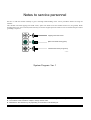
Notes to service personnel
Be sure to read this manual carefully to gain a thorough understanding of the correct procedures before servicing the
machine.
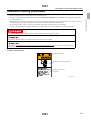
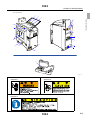
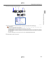
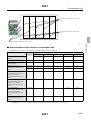
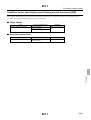
This machine uses both tapping truss head screws, spike truss head screws and washer head screw (for ground). When
attaching the screws once removed, make sure they are on their original positions. These screws are used for the place where
grounding is required.
Tapping truss head screw
Spike truss head screw (green)
Washer head screw (for ground)
SCREW
System Program: Ver. 1
! It is prohibited to show, provide, lend or transfer this manual to the others except the service personnel.
! The contents of this manual are subject to change without notice.
! Illustrations in this manual may vary depending on the model or manufacturing lot.
Microsoft, MS-DOS and Windows are registered trademarks of Microsoft Corporation in the United States and/or other
countries.
MultiMediaCard™ is a trademark of Infineon Technologies AG company in Germany and licensed to MMCA (MultiMediaCard
Association).
Other product and company names mentioned here in may be the trademarks of their respective owners. Symbols of
trademarks, ™ and ®, are not added.
Export Control
This Product shall be exported pursuant to the Japan Foreign Exchange and Foreign Trade Control Law, and Export Control of
Administration on Regulations of the U. S. Bureau of Industry and Security, and relevant laws and regulations. If Buyer reexports, directly or indirectly, the product to any country, the rules or regulations immediately preceding and relevant laws and
regulations of the countries concerned shall be applied.
Memory Stick is a trademark of Sony Corporation.
Explanation of manual
About the chapters
" 1. Cautions for work
Contains information on how to achieve safety in service operations.
Be sure to read these precautions thoroughly and carefully.
" 2. Replacement and adjustment of component parts
Describes how to remove or replace component parts and units, and how to adjust each part in replacement.
" 3. Mode
Describes the mode and how to install the programs.
" 4. Troubleshooting
This chapter explains the corrective action for trouble.
" 5. Operation sequence
Describes the operation sequence of system.
" 6. Electrical parts
Describes the PCBs used in this system.
" 7. Setup for service personnel
Describes the setups performed by the service personnel.
" 8. Wiring diagram
Wiring diagram
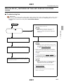
Symbols used in this manual
Definitions of the marks and symbols used in this manual are as follows:
This is called the alert symbol mark.
Text following this mark contains particularly important information concerning safety. Be sure to heed this information.
This mark is used in conjunction with the words DANGER, WARNING and CAUTION, according to the extent of
influence (injury) on persons or damage to physical property.
The Important symbol indicates operations or procedures require caution, instructions and supplementary explanations that
need to follow.
The pointing finger symbol indicates the manual or section where you can find additional information.
The Note symbol indicates useful information on functions or instructions.
iii
This page is intentionally blank.
iv
TABLE OF CONTENTS
Notes to service personnel
Explanation of manual ........................................................................................................................... iii
About the chapters ......................................................................................................................... iii
Symbols used in this manual ......................................................................................................... iii
1. Cautions for work
Description of warning (signal words) ...................................................................................... 1001
Description of warning (signal words) ...................................................................................................................1001
Location of warning labels ........................................................................................................ 1002
Location of warning labels .....................................................................................................................................1002
For safe operation .................................................................................................................... 1003
For safe operation ...................................................................................................................................................1003
Countermeasure for static electricity when replacing and maintaining the electronic parts ..................................1004
2. Replacement and adjustment of parts
Removing covers ..................................................................................................................... 2001
Removing covers ....................................................................................................................................................2001
Loading section ........................................................................................................................ 2101
Removing the film loading unit ..............................................................................................................................2101
Replacing the film cutter blades .............................................................................................................................2111
Adjusting the position of the cutter blade cover .....................................................................................................2121
Replacement of the film sensor unit .......................................................................................................................2141
Adjusting the position of the loading cover lock solenoid .....................................................................................2151
Adjusting the position of the film pressure solenoid ..............................................................................................2161
Processing tank section ........................................................................................................... 2201
Pitch adjustment of processing racks ......................................................................................................................2201
Dryer section ............................................................................................................................ 2311
Pitch adjustment of dryer rack ................................................................................................................................2311
Pitch adjustment of processing racks and dryer rack ..............................................................................................2321
Drive section ............................................................................................................................ 2401
Backlash adjustment of the drive gear ....................................................................................................................2401
Drive power supply unit ............................................................................................................ 2501
Replacing the battery pack ......................................................................................................................................2501
Replenishment package unit .................................................................................................... 2711
Replacing the probe [SM] .......................................................................................................................................2711
Adjusting the sensitivity of the replenisher sensor [SM] ........................................................................................2721
F replenishment unit ................................................................................................................. 2801
Removing F replenisher unit ..................................................................................................................................2801
Replacing the replenisher cartridge open/close motor ............................................................................................2802
Replacing the replenisher cartridge set ...................................................................................................................2803
Replacing the replenishment solution level sensor .................................................................................................2804
Output check of the replenishment cartridge cleaning valve and replenishment cartridge cleaning pump ...........2805
v
3. Mode
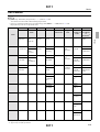
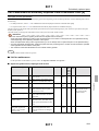
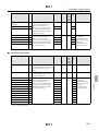
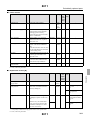
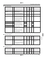
Mode ........................................................................................................................................ 3011
List of Modes ..........................................................................................................................................................3011
Mode configuration table [N] [SM] [F] ..................................................................................................................3012
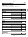
Passwords ................................................................................................................................ 3021
Approach to the password mode .............................................................................................................................3021
Approach to the service personnel mode ................................................................................................................3022
System program ....................................................................................................................... 3041
Reading the system program ..................................................................................................................................3041
SWITCH ................................................................................................................................... 3051
DRYER SWITCH ..................................................................................................................................................3051
TOTALING ............................................................................................................................... 3061
Changing the number of processed films ...............................................................................................................3061
Check ....................................................................................................................................... 3071
Input Check [N] ......................................................................................................................................................3071
INPUT CHECK [SM] .............................................................................................................................................3071
Input Check [F] .......................................................................................................................................................3071
Output Check [N] ...................................................................................................................................................3072
OUTPUT CHECK [SM] .........................................................................................................................................3072
Output Check [F] ....................................................................................................................................................3072
Version check .........................................................................................................................................................3075
ERROR RECORD ..................................................................................................................................................3077
LOADING MOTION RECORD ............................................................................................................................3079
FLOPPY ................................................................................................................................... 3091
Reading/Writing Data .............................................................................................................................................3091
SOFTWARE UPGRADE .......................................................................................................................................3093
FORMAT ................................................................................................................................................................3095
STANDARD SETTING ............................................................................................................. 3111
STANDARD SETTING 1 ......................................................................................................................................3111
STANDARD SETTING 2 ......................................................................................................................................3112
Data initialization ...................................................................................................................... 3131
Data initialization ....................................................................................................................................................3131
REPLENISH./REFIL.WATER ................................................................................................... 3141
REFILLING WATER AMOUNT 1 [N] ................................................................................................................3141
REFILLING WATER AMOUNT 1 [SM] .............................................................................................................3141
REFILLING WATER AMOUNT 2 [N] ................................................................................................................3142
REFILLING WATER AMOUNT 2 [SM] .............................................................................................................3142
CORRECTION [SM] .............................................................................................................................................3151
Replenishment/refill water ........................................................................................................ 3161
Pump amount setting [F] ........................................................................................................................................3161
Pump amount measurement [F] ..............................................................................................................................3162
vi
Replenishment/refill water ........................................................................................................ 3163
Refill water [F] .......................................................................................................................................................3163
Installation operation [F] ........................................................................................................................................3164
Operation mode set [F] ...........................................................................................................................................3165
Replenishment data initialization [F] ......................................................................................................................3166
REPLENISHER CONTROL DATA [F] ................................................................................................................3168
Replenishment rate [F] ..........................................................................................................................................3169
4. Troubleshooting
Symptoms due to the wiring connection failure .....................................................................................................4001
Symptoms resulted from blowout of fuse ...............................................................................................................4011
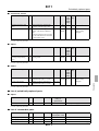
Error: Loading .......................................................................................................................... 4101
No. 001-01 FILM STOPPED ...............................................................................................................................4101
(N)
No. 002-01 FILM CUTTER NOT MOVED ........................................................................................................4101
(N)
No. 006-01 PRESSURE SENSOR ERROR .........................................................................................................4101
(N)
No. 007-01 CUTTER OPERATION ERROR ......................................................................................................4101
(N)
No. 009-01 CLOSE LOADING COVER .............................................................................................................4101
(N)
Error message: Processor 1 .................................................................................................... 4201
No. 021-01 PROCESS.SOLN.LEVEL TOO LOW .............................................................................................4201
(N)
No. 022 SOLUTION TEMP. ERROR .................................................................................................................4201
(N)
No. 023-01 SOLN. S-THERMO. ACTIVATED .................................................................................................4201
(N)
No. 024 CIRCULATION PUMP STOPPED .......................................................................................................4201
(N)
No. 027 THERMOSENSOR ERROR ..................................................................................................................4201
(N)
No. 028-01 DRYER FAN STOPPED ..................................................................................................................4201
(N)
No. 029[N] REPLENISHER TANK EMPTY ......................................................................................................4201
(N)
No. 030 WASTE SOLUTION TANK FULL .......................................................................................................4201
(N)
vii
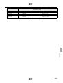
Error message: Processor 2 .................................................................................................... 4206
No. 031-01[N] TURN ON REPLENISHMENT SWITCH ..................................................................................4206
(N)
No. 032-01 TURN ON DRIVE SWITCH ............................................................................................................4206
(N)
No. 033-01 A/D CONVERTER ERROR .............................................................................................................4206
(N)
No. 034-01 CLOSE TOP COVER .......................................................................................................................4206
(N)
No. 036-01[SM] REPLENISHER / WATER SUPPLY .......................................................................................4206
PUMP OPERATION ERROR (N)
No. 037[SM] __ CHECK REMAINS IN .............................................................................................................4206
REPLENISHMENT PACKAGE (N)
No. 038[SM] __ REPLENISHMENT PACKAGE ..............................................................................................4206
NOT ATTACHED (N)
No. 040-01 DRIVE MOTION ERROR ................................................................................................................4206
(N)
No. 041-01 CIRCULATION LOW ......................................................................................................................4206
(N)
No. 042-01[N] REFILL WATER INTO ..............................................................................................................4206
REFILLING WATER TANK (N)
No. 043[SM] __ REPLENISHMENT PACKAGE ..............................................................................................4206
EMPTY (N)
No. 044-01 VOLTAGE SETTING ERROR ........................................................................................................4206
(N)
No. 045-01 SET THE RACK STOPPER .............................................................................................................4206
(N)
No. 046-01 TURN OFF THE CIRCUIT BREAKER ..........................................................................................4206
(N)
No. 047-01[SM] WATER SUPPLY TANK EMPTY ..........................................................................................4206
(N)
No. 051-01 SET DATE & TIME .........................................................................................................................4206
(N)
No. 052-01 INPUT MAIN DATA ........................................................................................................................4206
(N)
No. 053-01 POWER WENT DOWN ...................................................................................................................4206
(N)
Error: Floppy disk ..................................................................................................................... 4501
No. 081-01 FLOPPY DISK READING ERROR .................................................................................................4501
(N)
No. 082-01 FLOPPY DISK WRITING ERROR .................................................................................................4501
(N)
No. 083-01 FLOPPY DISK FORMAT. ERROR .................................................................................................4501
(N)
No. 084-01 DATA FLOPPY DISK ......................................................................................................................4501
NOT INSERTED YET
(N)
No. 085-01 SYSTEM PROGRAM FLOPPY .......................................................................................................4501
DISK NOT INSERTED YET
(N)
viii
Error message: Processor (F specification) ............................................................................. 4601
No. 201 [F] WATER IS INSUFFICIENT FOR ...................................................................................................4601
MIXING. ADD WATER
No. 202 [F] NC_ REPL CARTRIDGE USED UP. ..............................................................................................4601
REPLACE IT WITH A NEW ONE. (N)
No. 204 [F] NC_ SET REPL CARTRIDGE. .......................................................................................................4601
(N)
No. 206 [F] NC_ CARTRIDGE SETTING UNIT ...............................................................................................4601
DOES NOT GO UP.
(N)
No. 208 [F] NC_ CARTRIDGE SETTING UNIT ...............................................................................................4601
DOES NOT GO DOWN.
(N)
No. 212 [F] NC_ CLOSE THE DOOR OF THE .................................................................................................4601
CARTRIDGE SETTING UNIT.
(N)
No. 214 [F] NC_ CARTRIDGE SETTING UNIT ...............................................................................................4601
DOOR WAS OPEN WHILE MIXING.(N)
No. 216 [F] OUT OF WATER .............................................................................................................................4601
ADD WATER
No. 217 [F] WATER LEVEL DETEC ABNORMAL .........................................................................................4601
(N)
No. 220 [F] ____ REPL NOT PREPARED .........................................................................................................4601
(N)
No. 230 [F] ____ LEVEL DETECT ABNORMAL .............................................................................................4601
(N)
No. 235 [F] NC_ SETTING UNIT LIMIT ...........................................................................................................4601
DETECTOR ABNORMAL (N)
No. 237 [F] NC_ REPL LOWER LEVEL ABNORMAL ...................................................................................4601
(N)
No. 255 [F] ____ LOWER DETECTOR DOES NOT .........................................................................................4601
DETECT SOLUTION.
(N)
No. 268 [F] NC_ REPL SYSYTEM IS ABNORMAL ........................................................................................4601
FIND AND SOLVE TROUBLE
(N)
No. 270 [F] PROCESSING IMPOSSIBLE OWING TO .....................................................................................4601
N4R OR N1RB OUTPUT ABNORM. (N)
No. 272 [F] NC_ OPENING MOTOR OR UPPER .............................................................................................4601
DETECTOR IS ABNORMAL
(N)
No. 274 [F] N1R_ REPL PUMP, WASH VALVE ,OR ......................................................................................4601
STIR VALVE IS ABNORMAL
(N)
No. 275 [F] ____ REPL PUMP OR WASH VALVE ..........................................................................................4601
IS ABNORMAL (N)
No. 279 [F] ____ REPL PUMP IS ABNORMAL ...............................................................................................4601
(N)
No. 290 [F] ____ REPLENISHING PUMP .........................................................................................................4601
(N)
No. 300 [F] ___ SOLN LEVEL OF PROCESSING ............................................................................................4601
TANK WENT LOW.
(N)
No. 302 [F] WATER REFILLING SYSTEM NOT .............................................................................................4601
FUNCTIONING.
(N)
No. 306 [F] DATA FOR AUTO WATER REFILLING ......................................................................................4601
ABNORMAL
(N)
ix
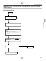
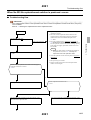
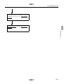
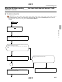
Troubleshooting flow ................................................................................................................ 4991
When No.206 NC_CARTRIDGE SETTING UNIT DOES NOT GO UP. and No.272 OPENING MOTOR OR
UPPER DETECTOR IS ABNORMAL occur ........................................................................................................4991
When No.208 NC_CARTRIDGE SETTING UNIT DOES NOT GO DOWN occurs ..........................................4991
When No.214 NC_CARTRIDGE SETTING UNIT DOOR WAS OPEN WHILE MIXING. occurs ..................4991
When No.220 No replenishment solution is produced. occurs ..............................................................................4991
When No.255 After opening _ _ _, the lower level does not become "with solution". occurs ..............................4991
When No.270 Cannot process because of pump amount error for N4R or N1RB. occurs ....................................4991
When No. 274 Error of N1R_replenisher pump, agitation value or cleaning value No.275 Error of _ _ _replenisher
pump or cleaning valve No.279_ __replenisher pump errorNo.290_ _ _replenisher pump system error occurs ..4991
When No.300 _ _ _ SOLN LEVEL OF PROCESSING TANK WENT LOW. occurred ....................................4991
Support documentation of trouble shooting ...........................................................................................................4991
5. Operation sequence
Operation sequence ................................................................................................................. 5101
Film processing operation .......................................................................................................................................5101
Replenishment operation ......................................................................................................... 5501
Replenisher mixing operation [F Specification] .....................................................................................................5501
6. Electrical parts
Change specification ................................................................................................................ 6001
Power supply specification (Single phase, two wires AC100-240 V) ....................................................................6001
Position of electrical parts ........................................................................................................ 6101
Loading section, control box section (position of electrical parts) .........................................................................6101
Processor section (positions of electrical parts) [N] ...............................................................................................6111
Processor section (positions of electrical parts) [SM] ............................................................................................6111
Processor section (positions of electrical parts) [F] ................................................................................................6111
Processor section (list for adjustment after replacing electrical parts) [F] .............................................................6151
Position of PCB, motor driver and power supply ...................................................................... 6201
Position [N] of PCB, motor driver and power supply ............................................................................................6201
Position [SM] of PCB, motor driver and power supply .........................................................................................6201
Position [F] of PCB, motor driver and power supply .............................................................................................6201
Description of PCB ................................................................................................................... 6301
Main control PCB (J391283) ..................................................................................................................................6301
Power PCB 1 (J391282) .........................................................................................................................................6311
Power PCB 2 (J391284) [N] ...................................................................................................................................6321
Power PCB 2 (J391284) [SM] ................................................................................................................................6321
Power PCB 2 (J391284) [F] ...................................................................................................................................6321
Connecting PCB (J490373) ....................................................................................................................................6331
SM sensor PCB (J391299) ......................................................................................................................................6341
Backup PCB (J390972), Battery pack (I085024) (option) .....................................................................................6351
F replenishment (J391323) .....................................................................................................................................6361
Description of the power supply ............................................................................................... 6401
DC power supply ....................................................................................................................................................6401
x
7. Setup for service personnel
Setup at installation .................................................................................................................. 7011
Setup at installation [N] [SM] .................................................................................................................................7011
Setup at installation [F] ...........................................................................................................................................7011
8. Appendix
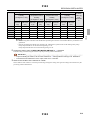
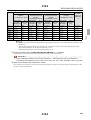
Periodically replaced parts ....................................................................................................... 8011
List of Maintenance/Periodically Replaced Parts/Consumable Parts [N] ..............................................................8011
List of Maintenance/Periodically Replaced Parts/Consumable Parts [SM] ...........................................................8011
List of Maintenance/Periodically Replaced Parts/Consumable Parts [F] ...............................................................8011
Condition list for check/replacement timing (service personnel) [N] ....................................................................8011
Condition list for check/replacement timing (service personnel) [SM] .................................................................8011
Condition list for check/replacement timing (service personnel) [F] .....................................................................8011
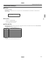
Service personnel tool list ........................................................................................................ 8031
Service personnel tool list [N] [F] ..........................................................................................................................8031
Service personnel tool list [SM] .............................................................................................................................8031
Table of wiring diagrams .......................................................................................................... 8900
Table of wiring diagrams ........................................................................................................................................8900
xi
This page is intentionally blank.
xii
1000
Cautions for work
Description of warning (signal words) .................................................................................... 1001
Description of warning (signal words) ................................................................................................................1001
Location of warning labels ..................................................................................................... 1002
Location of warning labels ..................................................................................................................................1002
For safe operation ................................................................................................................. 1003
For safe operation ................................................................................................................................................1003
Countermeasure for static electricity when replacing and maintaining the electronic parts ...............................1004
1000
1/1
1 Cautions for work
1.
1001
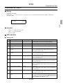
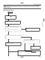
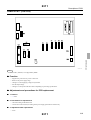
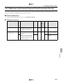
Description of warning (signal words)
Description of warning (signal words)
Description of warning (signal words)
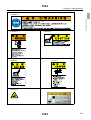
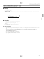
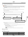
• The signal words used in this manual and found on labels, DANGER, WARNING and CAUTION, are assigned according to the
level of potential risk.
• Warning labels are located at or near the part of the system that pose the indicated danger. If ignored, death or serious injury occurs, or
the system breaks down. Be sure to follow the indications in the manuals and on the warning labels.
• The warnings include a signal word, the type and extent of the danger, and information to avoid danger.
• Carefully read and follow the warnings included in this manual and on the warning labels before operating the system.
This indicates situations that if not immediately avoided could result in serious injury or death.
This indicates situations that if not avoided could result in serious injury or death.
This indicates situations that if not avoided could result in non-life threatening injury. It is also used to indicate situations
which may cause damage to physical property.
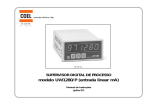
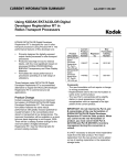
Example of warning label
Warning (signal word)
Symbol mark (warning indication)
Warning text (warning
indication)
SIGNALWORD
1001
1/1
1. Cautions for work
• Signal words identify the level of injuries that can potentially occur.
1002
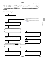
Location of warning labels
Location of warning labels
Location of warning labels
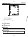
1. Cautions for work
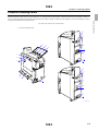
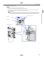
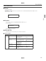
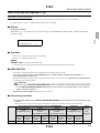
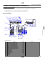
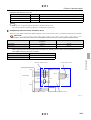
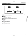
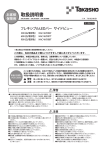
The following shows the locations, types and parts No. of warning labels on this machine. Follow the instructions on the labels carefully in
order to operate the machine safely and avoid accidents. Do not remove labels. If a label becomes illegible or comes off completely, contact
your place of purchase for label replacement.
The shape of the machine may somewhat differ.
for standard, SM specification
2
7
6
3
8
2
4
4
3
3
4
4
3
3
2
7
5
3
6
4
1
8
4
3
4
3
G086195
1002
1/3
1002
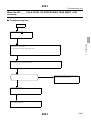
Location of warning labels
for F specification
3
2
4
1. Cautions for work
2
7
4
6
3
8
4
10
3
5
4
4
3
3
1
9
G086737
1
2
A022780-01
A022519-01
3
A234392-01
1002
2/3
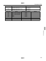
1002
Location of warning labels
4
5
1. Cautions for work
A234350-01
6
A022769-01
7
A234343-01
8
A079863-01
9
A079773-01
10
A087463-01
A059883-01
1002
3/3
1003
For safe operation
For safe operation
For safe operation
1. Cautions for work
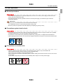
! General precautions
• Prior to any part replacement or mechanical adjustment, be sure to turn off the power supply and disconnect the
power code from the electrical outlet.
• Since the work which uses key operations cannot turn off the power supply, be careful enough to check the
mechanical operation.
IMPORTANT
• Ground wires are connected to the covers and units of this machine.
For reassembly, be sure to connect the ground wires as they were.
• Be sure to perform an operation check after replacing or adjusting any parts (or units).
! Precautions against electric shock
• If any case you have to take care of wiring for the power supply such as when moving the machine, ask a qualified
professional electrician for work. Do not forget to ground the machine.
• Pay attention to avoid shocks when performing troubleshooting, wiring check, or voltage/current measurement.
• When replacing a fuse, be sure to turn off the power supply and disconnect the power cord from the electrical outlet.
! Precautions for movable units
• There is a danger of hands being caught by the open/close covers or doors, or by the movable units.
When opening and closing covers or doors, be sure to hold them firmly.
When moving a unit manually, hold the specified parts only.
When working with a unit which automatically moves, or when working around such the units, be sure to turn off the
power supply.
If your hand is caught and you cannot move, immediately call for help to turn off the powoer supply.
1003
1/2
1003
For safe operation
! Precautions for operating heating section
1. Cautions for work
• If you directly touch them during operation or right after operation, you may get burnt.
When replacing parts or maintaining, make sure that the temperature is fully lowered.
Turn off the power supply, and after the temperature is fully lowered, perform the operation.
If you get burnt, cool the burn with flowing water and contact a physician as soon as possible.
! Precautions for using batteries
• If you replace batteries improperly, it may cause explosion or damage to the machine.
Use batteries which are specified by the manufacturer or the same types or equivalent as the specified ones.
Follow the handling instructions by battery manufacturer when you dispose the used batteries.
1003
2/2
1004
For safe operation
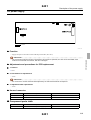
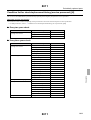
Countermeasure for static electricity when replacing and maintaining the
electronic parts
1. Cautions for work
If an electrically charged human body touches electronic parts such as PCBs, it may adversely affect the electronic parts.
When handling the electronic parts, be sure to use static-dissipative tools as below to prevent the components on the PCB from being
damaged due to static electricity.
Also use the static-dissipative tools for maintenance of the digital units or engines.
Static-dissipative tools
Description
Portable Static-Dissipative Field Service Kit
Remarks
Use this kit when replacing or installing/removing the electronic parts from the
machine. This kit consists of four items of Static-Dissipative Work Mat, Wrist
Strap, Ground Cord, and Alligator Clips.
Static-Dissipative conductive gloves
Use this to prevent that sebum on your hand adheres when you touch a PCB.
Wrist strap
Use this when checking the electronic parts.
• When using the static-dissipative tool, be sure to turn off the circuit breaker of the unit and the main power supply, and
wait 10 seconds or more to carry out the operation.
1004
1/1
2000
Replacement and adjustment of parts
Removing covers ................................................................................................................... 2001
Removing covers .................................................................................................................................................2001
Loading section ..................................................................................................................... 2101
Removing the film loading unit ...........................................................................................................................2101
Replacing the film cutter blades ..........................................................................................................................2111
Adjusting the position of the cutter blade cover ..................................................................................................2121
Replacement of the film sensor unit ....................................................................................................................2141
Adjusting the position of the loading cover lock solenoid ..................................................................................2151
Adjusting the position of the film pressure solenoid ...........................................................................................2161
Processing tank section ......................................................................................................... 2201
Pitch adjustment of processing racks ...................................................................................................................2201
Dryer section ......................................................................................................................... 2311
Pitch adjustment of dryer rack .............................................................................................................................2311
Pitch adjustment of processing racks and dryer rack ..........................................................................................2321
Drive section .......................................................................................................................... 2401
Backlash adjustment of the drive gear .................................................................................................................2401
Drive power supply unit ......................................................................................................... 2501
Replacing the battery pack ..................................................................................................................................2501
Replenishment package unit ................................................................................................. 2711
Replacing the probe [SM] ....................................................................................................................................2711
Adjusting the sensitivity of the replenisher sensor [SM] ....................................................................................2721
F replenishment unit .............................................................................................................. 2801
Removing F replenisher unit ...............................................................................................................................2801
Replacing the replenisher cartridge open/close motor ........................................................................................2802
Replacing the replenisher cartridge set ................................................................................................................2803
Replacing the replenishment solution level sensor ..............................................................................................2804
Output check of the replenishment cartridge cleaning valve and replenishment cartridge cleaning pump ........2805
2000
1/1
2 Replacement and adjustment of parts
2.
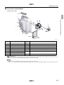
2001
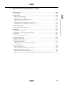
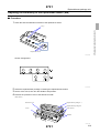
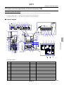
Removing covers
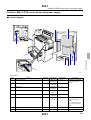
Removing covers
Removing covers
! Normal specification
Viewed from the front
2. Replacement and adjustment of parts
5
1
4
6
3
2
G073358
No.
Name
Screw
(Q'ty)
Remarks
1
Loading box section cover
4
2
Control box cover
2
3
Replenisher section cover
[Replenisher section door]
2
Remove together with the replenisher section door.
4
Sub-tank side cover
2
Knob screw
5
Sub-tank top cover
Not in use
6
Loading cover
4
Loosen the screw of upper right.
Remove the screws after opening the loading cover.
IMPORTANT
• Attach the loading cover while pulling it toward you and set it to center.
2001
1/5
2001
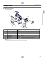
Removing covers
Viewed from back (When divided into the dryer unit cover and the replenisher pump cover)
1
2
5
4
G076009
No.
Name
Screw
(Q'ty)
1
Dryer cover
2
2
Waste solution tank cover
4
3
Dryer unit cover
2
4
Replenisher pump cover
2
5
Maintenance cover
2
Remarks
Knob screw
Remove the dryer cover and then remove the dryer cover.
Knob screw
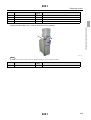
Viewed from back (When the dryer cover is one-piece type)
1
2
3
4
G080452
2001
2/5
2. Replacement and adjustment of parts
3
2001
No.
Name
Screw
(Q'ty)
Removing covers
Remarks
1
Dryer cover
2
2
Waste solution tank cover
4
Knob screw
3
Dryer unit cover
5
Remove the dryer cover and then remove the dryer cover.
4
Maintenance cover
2
Knob screw
2. Replacement and adjustment of parts
Viewed from back (When the T-15/S1-ll connection unit is installed)
1
G084602
NOTE
• When the T-15/S1-ll connection unit is installed, the dryer cover is subject to change.
No.
1
Name
Dryer cover
Screw
(Q'ty)
2
Remarks
Knob screw
2001
3/5
2001
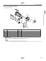
Removing covers
! Front side (SM specification)
Viewed from the front
5
2. Replacement and adjustment of parts
1
6
4
2
G075996
No.
1
Name
Screw
(Q'ty)
Loading box section cover
4
2
Control box cover
2
4
Sub-tank side cover
2
5
Sub-tank side cover
Not in use
6
Loading cover
4
Remarks
Loosen the screw of upper right.
Knob screw
Remove the screws after opening the loading cover.
IMPORTANT
• Attach the loading cover while pulling it toward you and set it to center.
NOTE
• The external view from the back is the same as that of normal specification.
Refer to ☞ Viewed from back (When divided into the dryer unit cover and the replenisher pump cover) for normal specification.
2001
4/5
2001
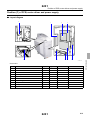
Removing covers
! Front side (F specification)
Viewed from the front
3
5
2. Replacement and adjustment of parts
1
7
4
6
8
2
G085860
No.
1
Name
Loading box section cover
Screw
(Q'ty)
4
2
Control box cover
3
Sub-tank side cover
4
Loading cover
4
5
Replenisher section cover
4
6
Replenisher section door 1
5
7
Replenisher section door 2
8
Replenisher section lower cover
Remarks
Loosen the screw of upper right.
2
Not in use
Remove the screws after opening the loading cover.
Remove the replenisher section doors with attaching frames.
2
IMPORTANT
• Attach the loading cover while pulling it toward you and set it to center.
NOTE
• The external view from the back is the same as that of normal specification.
Refer to ☞ Viewed from back (When divided into the dryer unit cover and the replenisher pump cover) for normal specification.
2001
5/5
2101
Loading section
Loading section
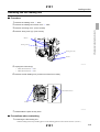
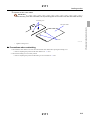
Removing the film loading unit
! Procedure
2. Replacement and adjustment of parts
1. Remove the loading cover. ☞ 2001
2. Remove the loading box section cover. ☞ 2001
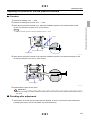
3. Remove the wiring cover. (Three screws)
4. Remove wiring cover (4). (Two screws)
Screws
Wiring cover
Wiring cover (4)
Screws
G075619
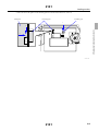
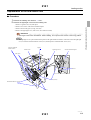
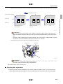
5. Unplug the connector(s).
• J/P59 (Power PCB 2) ☞ 6321
• J/P60 (Power PCB 2) ☞ 6321
6. Remove the film loading unit. (Loosen two of the four screws.)
Loosen these screws.
Screws
G075620
7. Reassemble the parts as they were.
! Precautions when reattaching
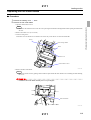
1. Positioning the film loading unit
1. Put the loading unit on the protruding part to fix the attaching position in the vertical direction. (Arrow 1)
2101
1/2
2101
Loading section
2. Move the unit to the right to fix the attaching position in the horizontal direction. (Arrow 2)
Protruding parts
Loading unit
Protruding part
1
2. Replacement and adjustment of parts
1
2
G075650
2101
2/2
2111
Loading section
Replacing the film cutter blades
! Procedure
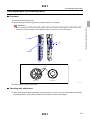
1. Remove the loading cover. ☞ 2001
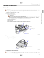
2. Remove the film cutter blade.
NOTE
• It is safe as the cutter does not come out even if pressing down the film cartridge holder when opening the cutter blade
set lever.
2. Remove the cutter cover. (Two screws)
3. Loosen a fixing screw.
Loosen the screw for about two revolutions. The screw may come off if it is loosen more than that.
Fixing
Film cartridge holder
Screw
Cutter cover
Cutter blade set lever
G075655
4. Remove the film cutter blade.
NOTE
• Removing will be easier by putting a thin and narrow plate under the cutter blade cover and taking out while holding
the cover.
• Handle the film cutter blade carefully not to cut your fingers.
Film cutter blade
G075656
2111
1/2
2. Replacement and adjustment of parts
1. Open the cutter blade set lever.
2111
Loading section
3. Replace the film cutter blade.
IMPORTANT
• When attaching a new film cutter blade, set the protruding parts into the holes of the film cutter blade securely.
Protruding parts
Holes
G075622
• Tighten a fixing screw.
! Precautions when reattaching
1. Check that the cutter blade cover does not touch the film cutter blade when opening the loading cover.
• Refer to Adjusting the position of the cutter blade cover. ☞ 2121
2. Check if the loading cover is securely locked.
• Refer to Adjusting the position of the loading cover lock solenoid. ☞ 2151
2111
2/2
2. Replacement and adjustment of parts
Film cutter blade
2121
Loading section
Adjusting the position of the cutter blade cover
! Procedure
1. Close the cutter blade set lever to which the loading cover was attached.
2. Adjust the attaching position of the cutter blade cover so that the gap A between the film guide and the cutter blade cover
becomes between 1 and 3 mm. (Two screws)
Film guide
A
Cutter blade cover
Screws
G075624
4. Adjust the position of the cutter blade cover horizontally. (Two screws)
1. Open the cutter blade set lever.
2. Remove the loading roller cover. (Two screws)
3. Remove light-tight cover (1). (Loosen one of the two screws.)
Light-tight cover (1)
Loosen this screw.
Screw
Screw
Loading roller cover
Cutter blade cover
G075617
4. Close the cutter blade set lever.
5. Push the film cartridge holder in the direction indicated by the arrow to operate the cutter blade.
6. Adjust the position of the cutter blade cover so that the gap A between the film cutter blade and the film cutter cover
becomes between 0 and 0.3 mm. (Two screws)
• Handle the film cutter blade carefully not to cut your fingers.
2121
1/2
2. Replacement and adjustment of parts
1. Remove the loading cover. ☞ 2001
2. Remove the loading box section cover. ☞ 2001
3. Adjust the gap of the film guide.
2121
Loading section
Cutter blade cover
Screws
Film cutter blade
G076088
! Precautions when reattaching
• None
2121
2/2
2. Replacement and adjustment of parts
Film cartridge holder
2141
Loading section
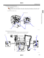
Replacement of the film sensor unit
! Procedure
1. Remove the loading unit. Refer to ☞ 2101.
2. Remove the light-tight cover from the loading unit.
1. Remove a guide screw (one) and spacer.
3. Remove the two idle gears. (E-ring: one each)
4. Remove the light-tight cover. (four screws, two of them are short)
IMPORTANT
• The length of the screws are different. When installing, do not put the short screws in the wrong position.
NOTE
• The light-tight cover is placed between the plates on the right and the left. When it is hard to remove the light-tight
cover, loosen the reinforcement bar screws (two) and the pressure solenoid holder screws (two).
Pressure solenoid
holder screws
Spacer
Guide screw
Light-tight cover
Sensor installation plate
Idle gears
Screws
Screws (short)
Reinforcement bar screws
Screws
G075659
2141
1/3
2. Replacement and adjustment of parts
2. Remove two screws of the sensor installation plate.
2141
Loading section
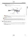
3. Remove the film detection roller.
1. Remove E-rings (two) and bearings (two).
IMPORTANT
• Thrust washer may be placed between an E-ring and a bearing. When assembling, return them as they
were.
2. Remove the film detection roller.
2. Replacement and adjustment of parts
Film detection roller
E-ring
E-ring
Bearings
G075660
4. Remove the film sensor unit.
1. Disconnect the connector (J/P142) and remove the cable from the cable binder.
2. Remove the screws (three screws) and the film sensor unit installation plate.
Screw
Screws
J/P142
Cable binder
Film sensor unit installation plate
G074371
2141
2/3
2141
Loading section
5. Replace the film sensor unit.
1. Remove the screws (two) and replace the sensor unit.
NOTE
• Spacer is placed between the film sensor unit and the film sensor unit installation plate.
Be careful not to lose the spacer.
Film sensor unit
Film sensor unit installation plate
Screw
Actuators
G074372
IMPORTANT
• When attaching the film sensor unit to the film sensor unit installation plate, attach the actuator not to touch the
film sensor unit installation plate.
6. Reassemble the parts as they were.
IMPORTANT
• When installing the film detection roller, check that the actuator does not touch the film detection roller.
If the actuator touches the film detection roller, adjust the installation position of the film sensor unit installation plate.
• Attach the loading cover while pulling the surplus space of the screw holes and adjust its horizontal direction to the
center.
! Checking after adjustment
1. When setting a leader card, check at ☞ 3071 if the film sensor and 135 film sensor are CLOSE in Input
Checks.
2. Process the test film and check if the detected film size is correct and if the error such as No.001-01
FILM STOPPED does not occur.
2141
3/3
2. Replacement and adjustment of parts
Screw
2151
Loading section
Adjusting the position of the loading cover lock solenoid
! Procedure
IMPORTANT
• Attach the loading cover while pulling it toward you and set it to center.
4. Adjust the position of the loading cover lock solenoid.
1. Close the loading cover.
2. Turn ON the loading cover lock solenoid in OUTPUT CHECK ☞ 3072 to lock the loading cover.
3. Pull the loading cover in the direction indicated by the arrow C to check that the loading cover does not open.
• When it opens:
Adjust the position of the loading cover lock solenoid in the direction A to lock it. (Two screws)
4. Turn OFF the loading cover lock solenoid.
5. When opening the loading cover, check that the pawl does not touch the lock pin.
• If the pawl touches the lock pin:
Adjust the position of the loading cover lock solenoid in the direction B so that the pawl does not touch the lock pin.
(Two screws)
IMPORTANT
• After adjusting the position of the loading cover lock solenoid in the direction B, be sure to turn ON the
loading cover lock solenoid and check that the loading cover does not open.
Loading cover lock solenoid
C
Screws
Pawl
B
A
Lock pin
G075639
5. Reassemble the parts as they were.
IMPORTANT
• Attach the loading cover while pulling the surplus space of the screw holes and adjust its horizontal direction to
the center following the same procedure of step 3.
! Checking after adjustment
1. Operate the loading cover lock solenoid in OUTPUT CHECK ☞ 3072 to check if the loading cover is
locked.
• Loading cover lock solenoid ON: Locked
• Loading cover lock solenoid OFF: Released
2151
1/1
2. Replacement and adjustment of parts
1. Remove the loading cover. ☞ 2001
2. Remove the loading box section cover. ☞ 2001
3. Attach the loading cover.
2161
Loading section
Adjusting the position of the film pressure solenoid
! Procedure
1. Remove the loading cover. ☞ 2001
2. Remove the loading box section cover. ☞ 2001
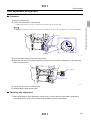
3. When the film pressure solenoid is on, adjust the installation position of the solenoid base so that
2. Replacement and adjustment of parts
section A is between 0.5 and 0.8 mm. (Four screws)
NOTE
• Turn on the film pressure solenoid with Output Check ☞ 3072.
Screws
A
Film pressure solenoid
Solenoid base
G074373
4. When the film pressure solenoid is off, adjust the installation position of the solenoid stopper so that
section B is between 0.5±0.5 mm. (Two screws)
B
Screws
Screws
Solenoid stopper
G075640
5. Reassemble the parts as they were.
IMPORTANT
• Attach the loading cover while pulling the surplus space of the screw holes and adjust its horizontal direction to
the center.
! Checking after adjustment
1. If the position of the film pressure solenoid was adjusted, be sure to process the leader card before
processing the films to check if the leader card is fed without fail.
2161
1/1
2201
Processing tank section
Processing tank section
Pitch adjustment of processing racks
! Procedure
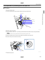
1. Remove the processing racks.
2. Set the drive gear and rack gears as the gear marks line in a straight.
Drive gear
Rack gears
Rack gears
G075628
Marks
Drive gear
Rack gear
G075629
3. Reassemble the parts as they were.
! Checking after adjustment
1. When performing the pitch adjustment of processing rack, be sure to process some leader cards before
processing films to check if the perforations of the leader card are not damaged.
2201
1/1
2. Replacement and adjustment of parts
IMPORTANT
• Due to the difference of each gear tooth quantity, it is only one point that all the gears can align at the center.
When all the marks are aligned, all the flattened sections of shafts turn in the same direction.
2311
Dryer section
Dryer section
Pitch adjustment of dryer rack
! Procedure
1. Remove the dryer rack.
2. Loosen two set-screws of inlet sprocket.
NOTE
• By setting the position of one set-screw up at the viewable side, it will be easy to tighten the screw after the adjustment.
Set-screw
Set-screws
Rotation
direction
Sprocket
G075632
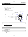
3. Insert the leader card from the inlet of dryer rack.
4. When the front end of the leader card touches the lower turn sprocket, rotate about 1/3 the dryer rack
gear counterclockwise.
Dryer rack gear
Leader card
G075636
5. Tighten two set-screws of inlet sprocket.
6. Reassemble the parts as they were.
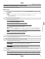
! Checking after adjustment
1. When performing the pitch adjustment of dryer rack, be sure to process some leader cards before
processing films to check if the perforations of the leader card are not damaged.
2311
1/1
2. Replacement and adjustment of parts
1. Set the position of the set-screws, one at the far side and the other at the upper side.
2321
Dryer section
Pitch adjustment of processing racks and dryer rack
! Procedure
1. Remove the dryer rack.
2. Loosen a fixing screw of worm collar to make the worm gear rotate freely.
2. Replacement and adjustment of parts
Fixing screw
Worm gear
Worm collar
Drive gear
G075634
3. Remove upper turn guide 5.
4. Insert the leader card into No. 7 processing rack and advance the leader card by turning the handle.
NOTE
• As for the leader card, using IX240 makes the following checking operation easier.
5. Stop the handle when the front end of the leader card reaches to the dryer inlet.
6. Face the fixing screw of the worm collar up.
Fixing screw
Worm collar
Drive gear
G075635
7. Attach the dryer rack.
2321
1/3
2321
Dryer section
8. Perform the pitch adjustment.
NOTE
• Perform the pitch adjustment looking through the frame cutout.
If it is not easy to look, light the inside of the frame cutout with flashlight.
1. Rotate the drive gear and the worm collar clockwise little by little. Stop them at the position where a tooth of the inlet
sprocket of the dryer rack comes into the first perforation of the leader card.
• Be sure to rotate the drive gear and the worm collar at the same time. If only the drive gear is turned, the
inlet sprocket of the dryer rack does not turn and the leader card hits the sprocket and bends in result.
Teeth of the inlet sprocket
Leader card
Processing
Perforation
Cutout of the frame part
G075638
2321
2/3
2. Replacement and adjustment of parts
IMPORTANT
2321
Dryer section
2. Adjust the teeth of the inlet sprocket to place at the center of the perforations (figure C below) by turning the worm collar.
Processing direction of the
Tooth of the inlet sprocket
A
B
C
Perforation
Rotate the worm collar
clockwise.
Rotate the worm collar
counterclockwise.
OK
G075637
IMPORTANT
• Be sure to adjust by turning the worm collar clockwise to bring the condition of figure C above from B.
When the condition is as figure A above, turn the worm collar counterclockwise first to bring the condition
as B.
• If the worm collar is adjusted from the condition of figure A above by turning it counterclockwise, the timing
may differ as much as the backlash of the gear as it drives to turn clockwise.
3. Push off the worm collar in the arrow direction and tighten a fixing screw.
Fixing screw
Worm collar
G075658
IMPORTANT
• Be careful not to turn the worm collar itself when fixing it.
If the worm collar turns itself, the timing will be different.
9. Reassemble the parts as they were.
! Checking after adjustment
1. When performing the pitch adjustment of processing racks and dryer rack, be sure to process some
leader cards before processing films to check if the perforations of the leader card are not damaged.
2321
3/3
2. Replacement and adjustment of parts
Leader card
2401
Drive section
Drive section
Backlash adjustment of the drive gear
! Procedure
1. Remove the dryer cover. ☞ 2001
2. Remove the dryer cover. ☞ 2001
3. Adjust the backlash of the drive gear.
2. Replacement and adjustment of parts
1. Loosen four screws of the drive motor base.
2. Adjust the attachment position of the drive motor base and make the drive gear backlash (part A) 0.2 mm to 0.5 mm.
A
Drive motor base
Screws
G075630
4. Reassemble the parts as they were.
2401
1/1
2501
Drive power supply unit
Drive power supply unit
Replacing the battery pack
! Procedure
IMPORTANT
1. Remove the control box cover. ☞ 2001
2. Remove the battery pack.
1. Disconnect J/P901 connector.
IMPORTANT
• Be sure to disconnect J/P901 connector (battery pack) first.
When the circuit breaker is turned off, the battery pack supplies DC+24 V to power PCB 2. Therefore, it
may damage power PCB 2 or the backup PCB if disconnecting J/P900 first.
2. Disconnect J/P900 connector.
3. Remove two screws.
4. Remove the battery pack holding the front side together with the PCB attaching plate.
J/P901
J/P900
PCB attaching plate
Screw
Battery pack
G075646
3. Replace the battery pack.
1. Remove the PCB attaching plate from the battery pack. (Two screws)
2. Replace the battery pack.
J/P901
PCB attaching plate
Screws
G075653
4. Reassemble the parts as they were.
IMPORTANT
• Connect J/P901 connector (battery pack) at the end.
2501
1/2
2. Replacement and adjustment of parts
• When replacing the battery pack, be sure to turn OFF not only the circuit breaker but also the drive switch.
2501
Drive power supply unit
If J/P900 connector is connected earlier, the battery pack supplies DC+24 V even with the circuit breaker turned off.
Therefore, it may damage power PCB 2 or the backup PCB at connecting J/P900.
• Write down the battery pack replacing date on the battery replacement label.
2. Replacement and adjustment of parts
• After the battery replacement, charging for more than 12 hours is necessary.
When a power failure occurred after charging less than 12 hours, the drive may stop before ejecting the film in
process.
2501
2/2
2711
Replenishment package unit
Replenishment package unit
Replacing the probe [SM]
! Procedure
Protection cover
G075651
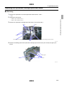
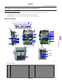
4. Unplug the tray unit connectors.
J/P700: Tray unit A (SM sensor PCB) ☞ 6341
J/P701: Tray unit B (SM sensor PCB) ☞ 6341
5. Remove the tray units A and B.
2. Lift it up.
Tray unit B
1. Pull the lever.
Tray unit A
G076069
2711
1/2
2. Replacement and adjustment of parts
1. Pull out the replenishment package unit.
2. Remove the replenishment package.
3. Remove the protection cover of the SM sensor PCB. (One screw)
2711
Replenishment package unit
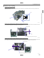
6. Remove the probe nuts and the probes.
STB
CD-A
CD-B
BL
FIX
Probe nut
Probe
O-ring
Probe holder
G076070
7. Set the new probes, then tighten the probe nuts securely using the probe replacing jig.
IMPORTANT
• The O-rings are attached to the new probes.
• The probe (including the O-ring) should be used properly for each solution.
For CD-A solution, use with the combination of the whole black probe and the O-ring marked with a white dot.
For other solutions, use with the combination of the probe which the resin part is brown and the O-ring marked
with a green dot.
• The probe replacing jig is a service personnel tool. Refer to Service personnel tool list.
8. Reassemble the parts as they were.
2711
2/2
2. Replacement and adjustment of parts
CD-C
2721
Replenishment package unit
Adjusting the sensitivity of the replenisher sensor [SM]
! Procedure
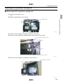
1. Clean the LED and detection sections of the replenisher sensor.
Replenisher sensor
G050894
Sensor arrangement
G075654
2. Attach the replenishment package containing the replenishment solution.
3. Set the valve chuck, then turn the handle to ON position.
4. Remove the protection cover of the SM sensor PCB.
(One screw)
Replenishment package F-1
Protection cover
Replenishment package F-2
Valve chucks
Screw
Handles
G075652
2721
1/3
2. Replacement and adjustment of parts
Trays
2721
Replenishment package unit
G075641
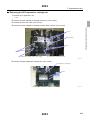
VR
Replenisher sensor
Counterclock
wise
Decreases the amount of light.
Clockwise
Increases the amount of light.
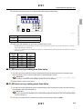
6. Adjust each VR depending on each LED condition which is OFF.
1. If LED turns ON by turning clockwise less than twice from the left most position, carry out the operation of ☞ If LED
turns on by rotating less than twice.
2. Carry out ☞ If LED turns on by rotating more than twice, if LED turns ON by turning clockwise more than twice from the
left most position.
Processing
solution
VR No.
LED No.
CD-B
VR1
LED1
CD-A
VR2
LED2
STB
VR3
LED3
CD-C
VR4
LED4
FIX
VR5
LED5
BL
VR6
LED6
! If LED turns on by rotating less than twice
1. Turn the VR of each replenisher sensor clockwise from the most left and when the LED lights up by
within 2 rotations, return to the most left and turn clockwise again 3 times.
IMPORTANT
• The condition is included that the LED lights up with the VR at the most left.
2. Reassemble the parts as they were.
! If LED turns on by rotating more than twice
1. Turn the VR of each replenisher sensor clockwise slowly while counting the rotation and stop turning it
at the position where the LED lights up.
IMPORTANT
• If the VR is turned too far clockwise, turn it counterclockwise until the LED goes off. Then turn it clockwise again
until the LED lights up.
2. Turn the VR of each sensor clockwise one rotation more from the position of Step 1.
2721
2/3
2. Replacement and adjustment of parts
5. Turn the VR of each sensor on the SM sensor PCB counterclockwise fully.
2721
Replenishment package unit
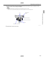
3. Replace the replenisher sensor and adjust its sensitivity if total number of the VR rotations of each
sensor exceeds 11 times in step 1 and step 2.
NOTE
• The maximum number of VR rotations for each replenisher sensor is 13 times.
• If the float in the replenishment package blocks off the replenisher sensor, the LED goes off.
2. Replacement and adjustment of parts
Replenishment
solution
Floats
Replenishment package
Replenisher sensor (detection)
Replenishment
solution
Probe
Replenisher sensor (LED)
G050897
4. Reassemble the parts as they were.
2721
3/3
2801
F replenishment unit
F replenishment unit
Removing F replenisher unit
! Procedure
1. Remove the replenisher cover, replenisher section doors 1 and 2, dryer cover and dryer unit cover.
☞ 2001
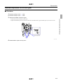
2. Unplug the connector(s).
2. Replacement and adjustment of parts
• J/P340: relay connector
• J/P341: relay connector
• J/P342: relay connector
J/P340, J/P341, J/P342
G085861
3. Remove the F replenisher unit. (five screws)
F replenishment unit
G085862
2801
1/1
2802
F replenishment unit
Replacing the replenisher cartridge open/close motor
! Removing
1. Remove the replenisher cover and replenisher section doors 1 and 2.
☞ 2001
2. Unplug the connector(s).
2. Replacement and adjustment of parts
• J/P270: relay connector (NC1)
• J/P271: relay connector (NC2)
3. Remove the replenisher cartridge open/close motor. (four screws each)
Screws
Screw
Screws
NC2 replenisher cartridge open/close motor
Screws
NC1 replenisher cartridge open/close motor
G085863
4. Remove the holding plate of the replenisher cartridge open/close motor (four screws) and gear (one
screw).
Holding plate
Screws
Screw
Gear
G085874
2802
1/2
2802
F replenishment unit
! Cautions when installing
Caution when installing the gear
Install the gear of the replenisher cartridge open/close motor so that there is 3 mm between outer surface of the gear and the motor
shaft end. (One screw)
Screw
Gear
G085875
Caution when installing the NC1 replenisher cartridge open/close motor
Fix the NC1 replenisher cartridge open/close motor with the detection plate of the NC1 cartridge set about 5 mm sticking out from the
NC1 replenisher cartridge position sensor (upper). (four fixing screws)
Detection plate
5 mm
NC1 replenisher cartridge position sensor (upper)
G085864
Caution when installing the NC2 replenisher cartridge open/close motor
Fix NC2 replenisher cartridge open/close motor with the cam roller of the drive gear located right side up and the detection plate of the
NC2 cartridge set about 5 mm protruded from NC2 replenisher cartridge position sensor (upper). (four fixing screws)
Detection plate
5 mm
NC2 replenisher cartridge position sensor (upper)
G085865
2802
2/2
2. Replacement and adjustment of parts
3 mm
2803
F replenishment unit
Replacing the replenisher cartridge set
! Removing the NC1 replenisher cartridge set
1. Remove the F replenisher unit.
☞ 2801
Guide frame
G085866
3. Remove the NC1 replenisher cartridge set sensor. (Two screws)
4. Remove the NC1 replenisher cartridge position sensor (upper). (Two screws)
NC1 replenisher cartridge set sensor
Screws
Screws
NC1 replenisher cartridge position sensor (upper)
G085867
5. Remove the NC1 replenisher cartridge set. (Three screws)
NC1 replenisher cartridge set
Screws
G085869
2803
1/2
2. Replacement and adjustment of parts
2. Remove the guide frame. (Four screws)
2803
F replenishment unit
! Removing the NC2 replenisher cartridge set
1. Remove the F replenisher unit.
☞ 2801
2. Replacement and adjustment of parts
2. Remove the NC2 replenisher cartridge set sensor. (Two screws)
3. Remove the door lock shaft. (Two screws)
4. Remove the NC2 replenisher cartridge position sensor (upper). (Two screws)
Screws
Door lock shaft
Screws
Screws
NC2 replenisher cartridge position sensor (upper)
NC2 replenisher cartridge set sensor
G085870
5. Remove the NC2 replenisher cartridge set. (Two screws)
NC2 replenisher cartridge set
Screws
G085873
2803
2/2
2804
F replenishment unit
Replacing the replenishment solution level sensor
! Procedure
1. Remove the replenishment solution level sensor you want to replace. (Two screws each)
☞ 6111
Example: N4R replenishment solution level sensor
### (lower) replenishment solution level sensor
### (middle) replenishment solution level sensor
### (upper) replenishment solution level sensor
Screws
Screws
G085878
NOTE
• ### (middle) replenishment solution level sensor is installed only for N1RB and N4R.
• # # # (upper) and (lower) replenishment solution level sensors of N1RA, N2R, and N3R should be replaced together.
• # # # (middle) and (lower) replenishment solution level sensors of N1RB and N4R should be replaced together.
! Checking after replacement
1. If you loosen the sensor installation portions fixed to the sensor shafts, fix the sensor installing portions
by referring to the figures below. (Two set-screws each)
Sensor installation figure (Unit:mm)
N4R
235.6
190.3
164.8
116.6
N3R
236.9
171.3
152
128.7
243
162.5
246.2
N2R
246.8
N1RB
12.0
N1RA
Sensor installation
Sensor shaft
G085877
2804
1/1
2. Replacement and adjustment of parts
2. Replace each replenishment solution level sensor. (Two screws each)
2805
F replenishment unit
Output check of the replenishment cartridge cleaning valve and
replenishment cartridge cleaning pump
• If you perform output check of replenishment cartridge cleaning valve and replenishment cartridge cleaning pump without using
hoses, the water may get into the replenisher tanks and adversely affect the replenishment solution.
1. Remove the replenishment cartridge.
2. Turn on the interlock switch (replenisher section door).
3. Lower Replenisher Cartridge Open/Close Motor at Output Check.
☞ 3072
4. Insert the hose of 13 mm diameter into the opening nozzle to be checked and fix the hose with adhesive
tape.
Hose
Opening nozzles
G085912
5. Operate Replenishment Cartridge Cleaning Valve at Output Check while keeping pressing the
SHIFT key to confirm if the cleaning water normally spout.
6. Remove the hose and more upwards the Replenisher Cartridge Open/Close Motor at Output Check.
2805
1/2
2. Replacement and adjustment of parts
! Procedure
F replenishment unit
2. Replacement and adjustment of parts
2805
This page is intentionally blank.
2805
2/2
3000
Mode
Mode ...................................................................................................................................... 3011
List of Modes .......................................................................................................................................................3011
Mode configuration table [N] [SM] [F] ...............................................................................................................3012
Passwords ............................................................................................................................. 3021
Approach to the password mode .........................................................................................................................3021
Approach to the service personnel mode .............................................................................................................3022
System program .................................................................................................................... 3041
Reading the system program ...............................................................................................................................3041
SWITCH ................................................................................................................................ 3051
DRYER SWITCH ...............................................................................................................................................3051
TOTALING ............................................................................................................................. 3061
Changing the number of processed films ............................................................................................................3061
Check .................................................................................................................................... 3071
Input Check [N] ...................................................................................................................................................3071
INPUT CHECK [SM] .........................................................................................................................................3071
Input Check [F] ....................................................................................................................................................3071
Output Check [N] ................................................................................................................................................3072
OUTPUT CHECK [SM] .....................................................................................................................................3072
Output Check [F] .................................................................................................................................................3072
Version check ......................................................................................................................................................3075
ERROR RECORD ...............................................................................................................................................3077
LOADING MOTION RECORD .........................................................................................................................3079
FLOPPY ................................................................................................................................ 3091
Reading/Writing Data ..........................................................................................................................................3091
SOFTWARE UPGRADE ....................................................................................................................................3093
FORMAT .............................................................................................................................................................3095
STANDARD SETTING .......................................................................................................... 3111
STANDARD SETTING 1 ...................................................................................................................................3111
STANDARD SETTING 2 ...................................................................................................................................3112
Data initialization ................................................................................................................... 3131
Data initialization ................................................................................................................................................3131
REPLENISH./REFIL.WATER ................................................................................................ 3141
REFILLING WATER AMOUNT 1 [N] .............................................................................................................3141
REFILLING WATER AMOUNT 1 [SM] ..........................................................................................................3141
REFILLING WATER AMOUNT 2 [N] .............................................................................................................3142
REFILLING WATER AMOUNT 2 [SM] ..........................................................................................................3142
CORRECTION [SM] ..........................................................................................................................................3151
Replenishment/refill water ..................................................................................................... 3161
Pump amount setting [F] .....................................................................................................................................3161
Pump amount measurement [F] ...........................................................................................................................3162
3000
1/2
3 Mode
3.
3000
Replenishment/refill water ..................................................................................................... 3163
Refill water [F] ....................................................................................................................................................3163
Installation operation [F] .....................................................................................................................................3164
Operation mode set [F] ........................................................................................................................................3165
Replenishment data initialization [F] ..................................................................................................................3166
REPLENISHER CONTROL DATA [F] .............................................................................................................3168
3 Mode
Replenishment rate [F] .......................................................................................................................................3169
3000
2/2
3011
Mode
Mode
List of Modes
NOTE
• [Password] : Protected by the password (+ − + −) Refer to ☞ 3021.
You cannot access the mode without entering the password.
• [Service] : Protected with the service personnel floppy disk (SHIFT + − + YES) Refer to ☞ 3022.
Displayed only in the service personnel mode.
1
2
3
4
5
6
SWITCH
TEMPERA
TURE
TOTALING
Check
FILM
POSITION
Program
timer
Mode
Supply
SWITCH*1
1
2
TEMPERAT TODAY'S
URE
ROLLS
DISPLAY
DISPLAY
Password
CONTRAST SOLUTION
TEMP.
SETTING
TOTAL
ROLLS
REPLENIS
FLOPPY
H./REFIL.W /STANDAR
ATER
D
SETTING*3
Date
Service
DATE AND REFILLING Service
TIME
WATER
STANDAR
SETTING
D SETTING
1
VERSION
Checking
Password
Service
3
BUZZER
VOLUME
THERMOSE
NSOR
CALIBRATI
ON
ERROR
RECORD
Service
Service
4
Dry
SWITCH
OUTPUT
Check
6
8
INPUT
Check
Password
5
7
Program
timer
SETTING
Supply
Service
FLOPPY
DISK
3. Mode
MAIN MENU
Service
REFILLING STANDAR
WATER
D SETTING
AMOUNT 1 2
MAINTENA Service
NCE DAY
REFILLING
SETTING
WATER
AMOUNT 2
Option
Service
DIGITAL
FLOWMET
ER*4
CORRECTI
ON*2
Service
Service
MOTION
RECORD
Adding
water*5
Service
DATA
INITIALIZA
TION
Service
Setting
operation*5
7
Service
Operation
mode*5
8
Service
Supply data
Initialization
9
*5
*1. Appears only with (N) specification.
*2. Appears only with (SM) specification.
3011
1/2
3011
Mode
3. Mode
*3. STANDARD SETTING appears only when the service personnel password is input.
*4. Appears only when setting DIGITAL FLOWMETER to ON in STANDARD SETTING 2.
*5. Appears only with (F) specification.
3011
2/2
3012
Mode
Mode configuration table [N] [SM] [F]
NOTE
• (OP) : Protected by the password (+ − + −) Refer to ☞ 3021.
You cannot access the mode without entering the password.
• (SP) : Protected with the service personnel floppy disk (SHIFT + − + YES) Refer to ☞ 3022.
Displayed only in the service personnel mode.
SWITCH
Item
Reference
5-15
BUZZER (OP)
1-3
DRYER SWITCH (SP)
AUTO/ON
☞ 3051
3. Mode
DISPLAY CONTRAST
TEMPERATURE
Item
TEMPERATURE DISPLAY
Reference
CD, BL
FIX, STB
DRY
ROOM TEMP. HUMID. (F) *1
SOLUTION TEMP. SETTING (OP)
CD, BL
FIX, STB
DRY1, DRY2
THERMOSENSOR CALIBRATION (OP)
CD, BL
FIX, STB
ROOM TEMP. (F)
*1. Display only when the environmental temperature and humidity meter turns on.
TOTALING
Item
Reference
☞ 3061
TODAY'S ROLLS
TOTAL ROLLS
Check
Item
INPUT CHECK
Reference
LOADING
☞ 3071
PROCESSOR
VERSION CHECK (OP)
MAIN (###)
ERROR RECORD (SP) *1
NUMBER, DATE, TIME, ERROR
OUTPUT CHECK (SP)
LOADING
☞ 3075
☞ 3077
☞ 3072
PROCESSOR
Digital flowmeter
##.#mL/min
Option
MOTION RECORD (SP)
NORMAL MOTION RECORD
☞ 3079
ERROR MOTION RECORD
SENSOR RECORD (GRAPHICS)
*1. Displays the details of the error by SHIFT.
PROGRAM TIMER MENU
Item
Date
Reference
DATE ##/##/## (YY/MM/DD)
3012
1/3
3012
Item
Mode
Reference
DAY *DAY
TIME ##:##:##
DATE AND TIME SETTING
DATE ##/##/## (YY/MM/DD)
DAY *DAY
TIME ##:##:##
PROGRAM TIMER SETTING
NO. ON/OFF DAY TIME *1
MAINTENANCE DAY SETTING
*DAY
*1. The settings of 20 patterns are possible.
REPLENISH./REFIL.WATER (N/SM specification)
REPLENISHMENT (N)
Reference
3. Mode
Item
TOTAL REPLENISH. AMOUNT
MANUAL REPLENISHMENT
BASIC REPL. AMOUNT (OP)
PUMP AMOUNT SETTING (OP)
PUMP AMOUNT MEASUREMENT (OP)
REPLENISHMENT LACK TIME (OP)
REPLENISHMENT (SM)
TOTAL/ REPL. REMAINS
BASIC REPL. AMOUNT (OP)
PUMP AMOUNT SETTING (OP)
PUMP AMOUNT MEASUREMENT (OP)
REPLENISHMENT RATE (SP)
SM FORCED REPL. (SP)
REFILLING WATER
REFILL WATER? (Y/N)
☞ 3141
REFILLING WATER AMOUNT 1 (N) (SP)
REFILLING WATER AMOUNT 1 (SM) (SP)
☞ 3142
REFILLING WATER AMOUNT 2 (N) (SP)
REFILLING WATER AMOUNT 2 (SM) (SP)
CORRECTION (SM) (SP)
REPLENISHMENT CORRECTION RATE
☞ 3151
REFILLING WATER LEVEL 2
REPLENISH./REFILL WATER (F)
Item
Supply
Reference
PUMP AMOUNT SETTING*1
PUMP AMOUNT MEASUREMENT*1
☞ 3161
☞ 3162
Environmental condition
REPLENISHER CONTROL DATA (SP)
REPLENISHMENT RATE (SP)
REFILL WATER (SP)
Evaporation rate at standby 0
☞ 3168
☞ 3169
☞ 3163
Evaporation rate (running)
Evaporation rate (power off)
Auto Cleaning Amount Setting
Refill water record
INSTALLATION OPERATION (SP)
Auto mixing
☞ 3164
Air removal
Replenisher mixing
OPERATION MODE SET (SP)
Auto refilling water
☞ 3165
THERMOHYGROMETER
3012
2/3
3012
Mode
Item
SUPPLY DATA INITIALIZATION (SP)
Reference
☞ 3166
NC1
NC2
NC1 + NC2
*1. Cannot change under the user level.
FLOPPY/STANDARD SETTING
Item
Floppy disk
Remarks
READING/WRITING
READ (FROM FLOPPY DISK)
☞ 3091
WRITE (TO FLOPPY DISK)
STANDARD SETTING 1 (SP)
STANDARD SETTING 2 (SP)
DATA INITIALIZATION (SP)
3012
3. Mode
☞ 3093
☞ 3095
☞ 3111
☞ 3112
☞ 3131
SOFTWARE UPGRADE
FORMAT
3/3
3021
Passwords
Passwords
Approach to the password mode
! EXPLANATION
• When attempting to approach to the mode, password inputting may be needed.
The mode necessary to input password is the password mode. Refer to ☞ 3011 List of Modes.
! Operation
1. Select the password mode, and press YES.
____
Y/N
3. Mode
PASSWORD?
SHIFT:→ + -
2. Enter the password.
+→−→+→−→YES
NOTE
• The content of input password is not displayed.
! How to release the password mode
• With the circuit breaker OFF or when proceeding to the program timer after the close down checks, the service personnel mode is
released.
3021
1/1
3022
Passwords
Approach to the service personnel mode
! EXPLANATION
• To approach to the service personnel mode, service personnel floppy disk and password input are necessary.
The service personnel mode will not appear until the protection is released by the service personnel floppy disk and inputting
password. Refer to ☞ 3011 List of Modes.
! Operation
1. Insert the service personnel floppy disk into the floppy disk drive.
2. Press MODE to display the MAIN MENU display.
***
3. Mode
*** MAIN MENU
SWITCHES
↑↓
Y/N
3. Enter the password.
SHIFT → + → − → + → YES
IMPORTANT
• Input the password within five seconds. If the access lamp of floppy disk drive lights when pressing YES of the
end of the password, it means the password could have been input within five seconds.
If the access lamp does not light, enter the password by starting with SHIFT again.
• When the password is recognized correctly, the letter S appears in the arrow part of the display.
• Password input is not accepted while processing film.
S
*** MAIN MENU
SWITCHES
↑↓
***
Y/N
! How to release the service personnel mode
• With the circuit breaker OFF or when proceeding to the program timer after the close down checks, the service personnel mode is
released.
3022
1/1
3041
System program
System program
Reading the system program
! EXPLANATION
• It switches the displayed language and reads the system program at replacing the main control PCB.
! Operation
1. When the circuit breaker is ON, turn OFF the circuit breaker.
2. Insert the system program floppy disk into the floppy disk drive.
3. Turn on the circuit breaker.
NOTE
• Reading the system program starts.
3. Mode
• When the displayed value achieves 100%, reading is complete. (It takes approx. three minutes.)
SOFT WARE IS BEING UPGRADE
##%
4. With an alarm sound, the message No. 51-01 SET DATE & TIME appears.
〈 51-01〉
SET DATE & TIME
(N)
5. Release the alarm and carry out the start up checks.
NOTE
• After releasing the alarm using YES + NO, the START CHECK display appears.
6. Read the system data. Refer to ☞ 3012.
7. Set the date and time. Refer to ☞ 3012.
3041
1/1
3051
SWITCH
SWITCH
DRYER SWITCH
! Display
Bringing up the display
MAIN MENU → ☞ Approach to the service personnel mode → SWITCHES: YES → DRYER SWITCH: YES
3. Mode
*** DRYER SWITCH ***
DRYER
AUTO
+Y/N
! Operation
• Using + or − switches AUTO and ON.
• Register by YES.
! EXPLANATION
! AUTO
Dryer operates when starting the film processing.
! ON
Dryer operates continuously even when the film is not processed.
NOTE
• With the circuit breaker OFF or when proceeding to the program timer after the close down checks, the setting is reset to AUTO.
• When setting to ON, dryer does not stop even though the drive is turned off.
3051
1/1
3061
TOTALING
TOTALING
Changing the number of processed films
Bringing up the display
MAIN MENU → ☞ Approach to the service personnel mode → TOTALING: YES
*** TOTALING ***
TODAY'S ROLLS
↑↓
Y/N
3. Mode
! Operation
• Using ↑ or ↓ switches TODAY'S ROLLS and TOTAL ROLLS.
• Pressing YES leads the operation forward.
! EXPLANATION
• The number of processed films can be changed voluntarily.
** TODAY'S ROLLS **
135-12 ____ 135-18 ____
↑ ↓ + − (RESET: SHIFT+NO)
• Using ↑ or ↓ switches the film type.
• Using + or − changes the number of processed films.
• Register by YES.
3061
1/1
3071
Check
Check
Input Check [N]
Description for each specification
For the specifications other than [N] specification, this section only gives description that differs from that for [N] specification. See below
for the description for each specification.
Reference
☞ INPUT CHECK [SM]
☞ Input Check [F]
! INPUT CHECK
Item
Specification
Reference
☞ Loading box (common to all
Loading section
Common to all specifications
Processor section
N specification
☞ Processor section (differs for
each specification)
SM specification
☞ Processor (SM)
☞ Processor (F)
F specification
3. Mode
specifications)
! Display
Bringing up the display
MAIN MENU → ☞ Approach to the service personnel mode → CHECK: YES → INPUT CHECK: YES
*** INPUT CHECK
LOADING
↑↓
***
Y/N
! Operation
• Using ↑ or ↓ switches LOADING and PROCESSOR.
• Pressing YES leads the operation forward.
• A buzzer sounds when the displayed sensor or limit switch turns CLOSE or ON.
** INPUT (LOADING) **
135 FILM SENSOR
OPEN
↑↓
(N)
• Using ↑ or ↓ switches the check item.
• Selecting NO returns to INPUT CHECK.
! EXPLANATION
! Loading box (common to all specifications)
No.
Display
Status
1
CLOSE/OPE 135 film sensor
N
CLOSE
When 135 film is detected
2
CLOSE/OPE Film sensor
N
CLOSE
When the film is detected.
3
ON/OFF
ON
When the sensor is turned CLOSE by the
detect plate
4
CLOSE/OPE FILM CARTRIDGES SENSOR
N
CLOSE
When the intermediate cartridge is set
5
CLOSE/OPE Pressure sensor
N
CLOSE
Film cartridge holder is positioned lower
Film jam sensor
3071
1/7
3071
No.
Check
Display
Status
6
CLOSE/OPE Film cutter sensor
N
CLOSE
When the film cutter is set
7
CLOSE/OPE Loading cover sensor
N
CLOSE
When the loading cover is closed
! Processor section (differs for each specification)
No.
Display
Status
ON/OFF
CD circulation pump
ON
When rotating correctly
2
ON/OFF
BL circulation pump
ON
When rotating correctly
3
ON/OFF
FIX1 circulation pump
ON
When rotating correctly
4
ON/OFF
FIX2 circulation pump
ON
When rotating correctly
5
ON/OFF
STB1 circulation pump
ON
When rotating correctly
6
ON/OFF
STB2 circulation pump
ON
When rotating correctly
7
ON/OFF
STB3 circulation pump
ON
When rotating correctly
8
ON/OFF
Rack stopper sensor
ON
When the rack stopper is set.
9
ON/OFF
Top cover sensor
ON
When the top cover is closed
10
ON/OFF
SAFETY THERMOSTAT
ON
Normal
11
ON/OFF
SAFETY THERMOSTAT(DRYER)
ON
Normal
12
ON/OFF
SOLUTION LEVEL
OFF
When the solution level is too low
13
ON/OFF
CD REFILLING LEVEL
OFF
When the solution level is too low
14
ON/OFF
BL REFILLING LEVEL
OFF
When the solution level is too low
15
ON/OFF
FIX1 REFILLING LEVEL
OFF
When the solution level is too low
16
ON/OFF
FIX2 REFILLING LEVEL
OFF
When the solution level is too low
17
ON/OFF
STB1 REFILLING LEVEL
OFF
When the solution level is too low
18
ON/OFF
STB2 REFILLING LEVEL
OFF
When the solution level is too low
19
ON/OFF
STB3 REFILLING LEVEL
OFF
When the solution level is too low
20
ON/OFF
Drive switch
ON
When the drive switch is ON
21
ON/OFF
DRIVE MOTOR SPEED SIGNAL
OFF
When the speed setting of DS1-8 drive motor
is LOW (specifications other than CN-16L
and CN-16S)
☞ 6311
22
ON/OFF
VOLTAGE SETTING 100
OFF
23
ON/OFF
VOLTAGE SETTING 110-115
OFF
24
ON/OFF
VOLTAGE SETTING 120
OFF
The voltage set with DS1 on the Power PCB 1
gets ON
☞ 6001
25
ON/OFF
VOLTAGE SETTING 200-208
OFF
26
ON/OFF
VOLTAGE SETTING 220-230
OFF
27
ON/OFF
VOLTAGE SETTING 240
OFF
28
ON/OFF
VOLTAGE SETTING ERROR
OFF
29
ON/OFF
CD REPLENISHER LEVEL
OFF
When no replenishment solution remains
30
ON/OFF
BL REPLENISHER LEVEL
OFF
When no replenishment solution remains
3. Mode
1
When the input voltage and the setting voltage
of DS1 are different
31
ON/OFF
FIX REPLENISHER LEVEL
OFF
When no replenishment solution remains
32
ON/OFF
WL REPLENISHER LEVEL
OFF
When no replenishment solution remains
33
ON/OFF
STB REPLENISHER LEVEL
OFF
When no replenishment solution remains
34
ON/OFF
CD WASTE SOLN. LEVEL
ON
When the waste solution tank is full
35
ON/OFF
BL WASTE SOLN. LEVEL
ON
When the waste solution tank is full
36
ON/OFF
FIX WASTE SOLN. LEVEL
ON
When the waste solution tank is full
37
ON/OFF
STB WASTE SOLN. LEVEL
ON
When the waste solution tank is full
38
ON/OFF
SUPPLY TANK LEVEL
OFF
When no water remains in the refilling water
tank
39
50/60Hz
Displays the frequency of input power supply.
3071
2/7
3071
No.
Display
ON/OFF
Status
Dryer fan
OFF
When the dryer fan stops
3. Mode
40
Check
3071
3/7
3071
Check
INPUT CHECK [SM]
Description for each specification
For the specifications other than [N] specification, this section only gives description that differs from that for [N] specification. See below
for the description for each specification.
Reference
☞ Input Check [N]
☞ Input Check [F]
! Processor (SM)
No.
Display
Status
ON/OFF
CD circulation pump
ON
When rotating correctly
2
ON/OFF
BL circulation pump
ON
When rotating correctly
3
ON/OFF
FIX1 circulation pump
ON
When rotating correctly
4
ON/OFF
FIX2 circulation pump
ON
When rotating correctly
5
ON/OFF
STB1 circulation pump
ON
When rotating correctly
6
ON/OFF
STB2 circulation pump
ON
When rotating correctly
7
ON/OFF
STB3 circulation pump
ON
When rotating correctly
8
ON/OFF
Rack stopper sensor
ON
When the top cover is closed
9
ON/OFF
Top cover sensor
ON
Normal
10
ON/OFF
SAFETY THERMOSTAT
ON
Normal
11
ON/OFF
SAFETY THERMOSTAT(DRYER)
ON
Normal
12
ON/OFF
SOLUTION LEVEL
OFF
When the solution level is too low
13
ON/OFF
CD REFILLING LEVEL
OFF
When the solution level is too low
14
ON/OFF
BL REFILLING LEVEL
OFF
When the solution level is too low
15
ON/OFF
FIX1 REFILLING LEVEL
OFF
When the solution level is too low
16
ON/OFF
FIX2 REFILLING LEVEL
OFF
When the solution level is too low
17
ON/OFF
STB1 REFILLING LEVEL
OFF
When the solution level is too low
18
ON/OFF
STB2 REFILLING LEVEL
OFF
When the solution level is too low
19
ON/OFF
STB3 REFILLING LEVEL
OFF
When the solution level is too low
20
ON/OFF
Drive switch
ON
When the drive switch is ON
21
ON/OFF
DRIVE MOTOR SPEED SIGNAL
OFF
When the speed setting of DS1-8 drive motor
is LOW (specifications other than CN-16L
and CN-16S)
☞ 6311
22
ON/OFF
VOLTAGE SETTING 100
ON
23
ON/OFF
VOLTAGE SETTING 110-115
OFF
The voltage set with DS1 on the Power PCB 1
gets ON
☞ 6001
24
ON/OFF
VOLTAGE SETTING 120
OFF
25
ON/OFF
VOLTAGE SETTING 200-208
OFF
26
ON/OFF
VOLTAGE SETTING 220-230
OFF
27
ON/OFF
VOLTAGE SETTING 240
OFF
28
ON/OFF
VOLTAGE SETTING ERROR
OFF
When the input voltage and the setting voltage
are different
29
ON/OFF
CD-A REPL. PUMP SENSOR
ON
Home position
30
ON/OFF
CD-B REPL. PUMP SENSOR
ON
Home position
31
ON/OFF
CD-C REPL. PUMP SENSOR
ON
Home position
32
ON/OFF
CD-W WATER PUMP SENSOR
ON
Home position
33
ON/OFF
BL REPL. PUMP SENSOR
ON
Home position
34
ON/OFF
FIX REPL. PUMP SENSOR
ON
Home position
35
ON/OFF
FIX-W WATER PUMP SENSOR
ON
Home position
36
ON/OFF
STB REPL. PUMP SENSOR
ON
Home position
3071
3. Mode
1
4/7
3071
Display
Status
37
ON/OFF
STB-W water supply pump sensor
ON
Home position
38
ON/OFF
REPL. PACKAGE SE.(F1)
ON
When the replenishment package is set
39
ON/OFF
REPL. PACKAGE SE.(F2)
ON
When the replenishment package is set
40
ON/OFF
REPL.SOLN. SE.(CD-A)
ON
When no replenishment solution remains
41
ON/OFF
REPL.SOLN. SE.(CD-B)
ON
When no replenishment solution remains
42
ON/OFF
REPL.SOLN. SE.(CD-C)
ON
When no replenishment solution remains
43
ON/OFF
REPL.SOLN. SE.(BL)
ON
When no replenishment solution remains
44
ON/OFF
REPL.SOLN. SE.(FIX)
ON
When no replenishment solution remains
45
ON/OFF
REPL.SOLN. SE.(STB)
ON
When no replenishment solution remains
46
ON/OFF
STB REPLENISHER LEVEL
OFF
When no replenishment solution remains
47
ON/OFF
CD WASTE SOLN. LEVEL
ON
When the waste solution tank is full
48
ON/OFF
BL WASTE SOLN. LEVEL
ON
When the waste solution tank is full
49
ON/OFF
FIX WASTE SOLN. LEVEL
ON
When the waste solution tank is full
50
ON/OFF
STB WASTE SOLN. LEVEL
ON
When the waste solution tank is full
51
ON/OFF
SUPPLY TANK LEVEL
OFF
When the solution level is too low
52
53
50/60Hz
ON/OFF
3. Mode
No.
Check
Displays the frequency of input power supply.
Dryer fan
OFF
3071
When the dryer fan stops
5/7
3071
Check
Input Check [F]
Description for each specification
For the specifications other than [N] specification, this section only gives description that differs from that for [N] specification. See below
for the description for each specification.
Reference
☞ Input Check [N]
☞ INPUT CHECK [SM]
! Processor (F)
No.
Display
Status
ON/OFF
N1 CIRCULATION PUMP
ON
When rotating correctly
2
ON/OFF
N2 CIRCULATION PUMP
ON
When rotating correctly
3
ON/OFF
N31 CIRCULATION PUMP
ON
When rotating correctly
4
ON/OFF
N32 CIRCULATION PUMP
ON
When rotating correctly
5
ON/OFF
N41 CIRCULATION PUMP
ON
When rotating correctly
6
ON/OFF
N42 CIRCULATION PUMP
ON
When rotating correctly
7
ON/OFF
N43 CIRCULATION PUMP
ON
When rotating correctly
8
ON/OFF
Rack stopper sensor
ON
When the top cover is closed
9
ON/OFF
Top cover sensor
ON
Normal
10
ON/OFF
SAFETY THERMOSTAT
ON
Normal
11
ON/OFF
SAFETY THERMOSTAT(DRYER)
ON
Normal
12
ON/OFF
SOLUTION LEVEL
OFF
When the solution level is too low
13
ON/OFF
N1 SOLN LEVEL
OFF
When the solution level is too low
14
ON/OFF
N2 SOLN LEVEL
OFF
When the solution level is too low
15
ON/OFF
N31 SOLN LEVEL
OFF
When the solution level is too low
16
ON/OFF
N32 SOLN LEVEL
OFF
When the solution level is too low
17
ON/OFF
N41 SOLN LEVEL
OFF
When the solution level is too low
18
ON/OFF
N42 SOLN LEVEL
OFF
When the solution level is too low
19
ON/OFF
N43 SOLN LEVEL
OFF
When the solution level is too low
20
ON/OFF
Drive switch
ON
When the drive switch is ON
21
ON/OFF
DRIVE MOTOR SPEED SIGNAL
OFF
When the speed setting of DS1-8 drive motor
is LOW (specifications other than CN-16L
and CN-16S)
☞ 6311
22
ON/OFF
VOLTAGE SETTING 100
ON
23
ON/OFF
VOLTAGE SETTING 110-115
OFF
The voltage set with DS1 on the Power PCB 1
gets ON
☞ 6001
3. Mode
1
24
ON/OFF
VOLTAGE SETTING 120
OFF
25
ON/OFF
VOLTAGE SETTING 200-208
OFF
26
ON/OFF
VOLTAGE SETTING 220-230
OFF
27
ON/OFF
VOLTAGE SETTING 240
OFF
28
ON/OFF
VOLTAGE SETTING ERROR
OFF
When the input voltage and the setting voltage
are different
29
ON/OFF
INTERLOCK (REPL SEC 1)
ON
When replenisher section door 1 is closed
30
ON/OFF
INTERLOCK (REPL SEC 2)
ON
When replenisher section door 2 is closed
31
ON/OFF
NC1 replenisher cartridge set sensor
ON
When the NC1 replenisher cartridge is
detected.
32
ON/OFF
NC2 replenisher cartridge set sensor
ON
When the NC2 replenisher cartridge is
detected.
33
ON/OFF
NC1 replenisher cartridge position sensor
(upper)
ON
When the NC1 replenisher cartridge is set.
3071
6/7
3071
Display
Status
34
ON/OFF
NC1 replenisher cartridge position sensor
(lower)
ON
When the NC1 replenisher cartridge is
opened.
35
ON/OFF
NC2 replenisher cartridge position sensor
(upper)
ON
When the NC2 replenisher cartridge is set.
36
ON/OFF
NC2 replenisher cartridge position sensor
(lower)
ON
When the NC2 replenisher cartridge is
opened.
37
ON/OFF
N1RA (upper) replenishment solution level
sensor
ON
When the replenishment solution is detected
38
ON/OFF
N1RA (lower) replenishment solution level
sensor
ON
When the replenishment solution is detected
39
ON/OFF
N2 (upper) replenishment solution level
sensor
ON
When the replenishment solution is detected
40
ON/OFF
N2R (lower) replenishment solution level
sensor
ON
When the replenishment solution is detected
41
ON/OFF
N3R (upper) replenishment solution level
sensor
ON
When the replenishment solution is detected
42
ON/OFF
N3R (lower) replenishment solution level
sensor
ON
When the replenishment solution is detected
43
ON/OFF
N4R (upper) replenishment solution level
sensor
ON
When the replenishment solution is detected
44
ON/OFF
N4R (middle) replenishment solution level
sensor
ON
When the replenishment solution is detected
45
ON/OFF
N4R (lower) replenishment solution level
sensor
ON
When the replenishment solution is detected
46
ON/OFF
N1RB (upper) replenishment solution level
sensor
ON
When the replenishment solution is detected
47
ON/OFF
N1RB (middle) replenishment solution level
sensor
ON
When the replenishment solution is detected
48
ON/OFF
N1RB (lower) replenishment solution level
sensor
ON
When the replenishment solution is detected
49
ON/OFF
CD WASTE SOLN. LEVEL
ON
When the waste solution tank is full
50
ON/OFF
BL WASTE SOLN. LEVEL
ON
When the waste solution tank is full
51
ON/OFF
FIX WASTE SOLN. LEVEL
ON
When the waste solution tank is full
52
ON/OFF
STB WASTE SOLN. LEVEL
ON
When the waste solution tank is full
53
ON/OFF
Replenishment solution level sensor (upper
water level)
ON
When the replenishment solution is detected
54
ON/OFF
Replenishment solution level sensor (lower
water level)
ON
When the replenishment solution is detected
ON/OFF
Dryer fan
OFF
When the dryer fan stops
55
56
50/60Hz
Displays the frequency of input power supply.
3071
7/7
3. Mode
No.
Check
3072
Check
Output Check [N]
Description for each specification
For the specifications other than [N] specification, this section only gives description that differs from that for [N] specification. See below
for the description for each specification.
Reference
☞ OUTPUT CHECK [SM]
☞ Output Check [F]
! Output Check
Item
Specification
Reference
☞ Loading box (common to all
Loading section
Common to all specifications
Processor section
N specification
☞ Processor (differs for each
specification)
SM specification
☞ Processor (SM)
☞ Processor (F)
F specification
3. Mode
specifications)
! Display
Bringing up the display
MAIN MENU → ☞ Approach to the service personnel mode → CHECK: YES → OUTPUT CHECK: YES
*** OUTPUT CHECK ***
LOADING
↑↓
Y/N
! Operation
• Using ↑ or ↓ switches LOADING and PROCESSOR.
• Pressing YES leads the operation forward.
• The displayed electrical part can be operated.
** OUTPUT (LOADING)**
LOADING COVER LOCK SOLENOID
↑↓
Y/N
• Using ↑ or ↓ switches the check item.
• Selecting NO returns to INPUT CHECK.
! EXPLANATION
! Loading box (common to all specifications)
No.
Display
Operation
1
LOADING COVER LOCK SOLENOID
Operates while pressing YES.
2
PRESSURE SOLENOID
Operates while pressing YES.
3
PRESSURE ENABLE SIGNAL
The signal is output while pressing YES.
4
READY LAMP (RED)
Lights while pressing YES.
5
READY LAMP (GREEN)
Lights while pressing YES.
6
BUZZER VOLUME
A buzzer sounds while pressing YES.
NOTE
• PRESSURE ENABLE SIGNAL
3072
1/5
3072
Check
• PRESSURE ENABLE SIGNAL is the signal output to turn on the pressure solenoid as a hardware.
Although the pressure solenoid is turned on by receiving the film rear end detecting signal from the pressure sensor by a
software in cutting the film rear end normally, it is also controlled by a hardware so as to turn the pressure solenoid on
without fail.
• At Output Check, the pressure solenoid operates when turning the pressure sensor to CLOSE with pressing YES.
! Processor (differs for each specification)
1
Display
Operation
CD HEATER
ON while pressing YES
2
BL HEATER
ON while pressing YES
3
STB HEATER
ON while pressing YES
4
COOLING FAN
Operates while pressing YES.
5
DRYER HEATER 1
ON while pressing YES
6
DRYER HEATER 2
ON while pressing YES
7
DRYER FAN
Operates while pressing YES.
8
CIRCULATION PUMP
Operates while pressing YES.
9
AERATION PUMP
Operates while pressing YES.
10
COOL. WATER SOLENOID VALVE
Operates while pressing YES.
11
CD
REFILLING WATER PUMP
Operates for 10 seconds by pressing YES.
12
BL
REFILLING WATER PUMP
Operates for 10 seconds by pressing YES.
13
FIX1 REFILLING WATER PUMP
Operates for 10 seconds by pressing YES.
14
FIX2 REFILLING WATER PUMP
Operates for 10 seconds by pressing YES.
15
STB1 REFILLING WATER PUMP
Operates for 10 seconds by pressing YES.
16
STB2 REFILLING WATER PUMP
Operates for 10 seconds by pressing YES.
17
STB3 REFILLING WATER PUMP
Operates for 10 seconds by pressing YES.
18
CLEANING PUMP
Operates for 10 seconds by pressing YES.
19
CD
Operates while pressing YES.
20
BL
21
FIX
22
WL
23
STB
24
EXHAUST FAN
REPLENISHER PUMP
REPLENISHER PUMP
3. Mode
No.
Operates while pressing YES.
REPLENISHER PUMP
Operates while pressing YES.
REPLENISHER PUMP
Operates while pressing YES.
REPLENISHER PUMP
Operates while pressing YES.
Operates while pressing YES.
3072
2/5
3072
Check
OUTPUT CHECK [SM]
Description for each specification
For the specifications other than [N] specification, this section only gives description that differs from that for [N] specification. See below
for the description for each specification.
Reference
☞ Output Check [N]
☞ Output Check [F]
! Processor (SM)
Display
Operation
1
CD HEATER
ON while pressing YES
2
BL HEATER
ON while pressing YES
3
STB HEATER
ON while pressing YES
4
COOLING FAN
Operates while pressing YES.
5
DRYER HEATER 1
ON while pressing YES
6
DRYER HEATER 2
ON while pressing YES
7
DRYER FAN
Operates while pressing YES.
8
CIRCULATION PUMP
Operates while pressing YES.
9
AERATION PUMP
Operates while pressing YES.
10
COOL. WATER SOLENOID VALVE
Operates while pressing YES.
11
BL
REFILLING WATER PUMP
Operates while pressing YES.
12
FIX1 REFILLING WATER PUMP
Operates while pressing YES.
13
STB1 REFILLING WATER PUMP
Operates while pressing YES.
14
STB2 REFILLING WATER PUMP
Operates while pressing YES.
15
CLEANING PUMP
16
CD-A REPLENISHER PUMP
**1
Operates while pressing YES.
17
CD-B
REPLENISHER PUMP
**1
Operates while pressing YES.
18
CD-C
REPLENISHER PUMP
**1
19
CD-W WATER SUPPLY PUMP
20
BL
REPLENISHER PUMP
REPLENISHER PUMP
Operates while pressing YES.
Operates while pressing YES.
*1
*
Operates while pressing YES.
**1
Operates while pressing YES.
*1
Operates while pressing YES.
21
FIX
22
FIX-W WATER SUPPLY PUMP
**1
Operates while pressing YES.
23
STB
*1
Operates while pressing YES.
24
STB-W WATER SUPPLY PUMP
25
EXHAUST FAN
REPLENISHER PUMP
3. Mode
No.
*
*
**1
Operates while pressing YES.
Operates while pressing YES.
*1. At the output check, the mark ∗ appears when the pump home sensor has detected the home position while the pump is rotating.
3072
3/5
3072
Check
Output Check [F]
Description for each specification
For the specifications other than [N] specification, this section only gives description that differs from that for [N] specification. See below
for the description for each specification.
Reference
☞ Output Check [N]
☞ OUTPUT CHECK [SM]
! Processor (F)
Display
Operation
1
N1 HEATER
ON while pressing YES
2
N2 HEATER
ON while pressing YES
3
N4 HEATER
ON while pressing YES
4
COOLING FAN
Operates while pressing YES.
5
DRYER HEATER 1
ON while pressing YES
6
DRYER HEATER 2
ON while pressing YES
7
DRYER FAN
Operates while pressing YES.
8
CIRCULATION PUMP
Operates while pressing YES.
9
AERATION PUMP
Operates while pressing YES.
10
COOL. WATER SOLENOID VALVE
Operates while pressing YES.
11
NC1JÓ°À° ã¸
* **1*4
Operates while pressing YES.
12
NC1JÓ°À° º~
* **1*4
Operates while pressing YES.
13
NC2JÓ°À° ã¸
*
**1*4
Operates while pressing YES.
14
NC2JÓ°À° º~
* **1*4
3. Mode
No.
Operates while pressing YES.
15
N1RA CARTRIDGE CLEANING VALVE
*2*5
Operates while pressing YES.
16
N2R CARTRIDGE CLEANING VALVE*2*5
Operates while pressing YES.
17
N3R CARTRIDGE CLEANING
VALVE*2*5
Operates while pressing YES.
18
N4R CARTRIDGE CLEANING VALVE*2*5
Operates while pressing YES.
19
*2*5
N1RB CARTRIDGE CLEANING VALVE
Operates while pressing YES.
20
N1W ADDING WATER VALVE*3
Operates while pressing YES.
22
*3
N2W ADDING WATER VALVE
Operates while pressing YES.
23
N3W ADDING WATER VALVE*3
Operates while pressing YES.
24
N42W ADDING WATER VALVE
*3
Operates while pressing YES.
25
N43W ADDING WATER VALVE*3
Operates while pressing YES.
26
*2
N1RA AGITATION VALVE
Operates while pressing YES.
27
N1RB AGITATION VALVE*2
Operates while pressing YES.
28
N1RA REPLENISHER PUMP
Operates while pressing YES.
29
N2R REPLENISHER PUMP
Operates while pressing YES.
30
N3R REPLENISHER PUMP
Operates while pressing YES.
31
N4R REPLENISHER PUMP
Operates while pressing YES.
32
N1RB REPLENISHER PUMP
Operates while pressing YES.
33
N3W CASCADE REPLENISHER PUMP
Operates while pressing YES.
34
AUTO CLEANING VALVE *2
Operates while pressing YES.
35
EXHAUST FAN
Operates while pressing YES.
*1. When the replenisher cartridge is set, before operating the message The replenisher cartridge is set. appears.
*2. When operating the cleaning valve, agitation valve and auto cleaning valve while pressing the SHIFT key, the replenisher cartridge cleaning
pump operates at the same time.
*3. When operating the adding water valve while pressing the SHIFT key, the adding water replenisher pump operates at the same time.
*4. When the replenisher cartridge position sensor (upper) is ON, the left ∗ turns ON. When the replenisher cartridge position sensor (lower) is ON,
the right ∗ turns ON.
3072
4/5
3072
Check
3. Mode
*5. If the cleaning water gets into a replenisher tank, the amount of replenishment solution changes. Insert a hose into the opening nozzle and execute
Output Check preventing the water getting into the tank.
When you insert a hose into the opening nozzle, we recommend you to operate Replenisher Cartridge Open/Close Motor and lower the
replenisher cartridge set section.
For details, refer to ☞ 2805.
3072
5/5
3075
Check
Version check
! Display
Bringing up the display
MAIN MENU → ☞ Approach to the service personnel mode → CHECK: YES → VERSION CHECK: YES
3. Mode
*** VERSION CHECK ***
MAIN
____ (______)
(N)
! EXPLANATION
• The version of the system program is displayed.
In ( ), the version of Boot program is displayed.
3075
1/1
3077
Check
ERROR RECORD
! Display
Bringing up the display
MAIN MENU → ☞ Approach to the service personnel mode → CHECK: YES → ERROR RECORD: YES
3. Mode
** ERROR RECORD **
1 04.03.17 08:00 030-0004
↑↓ (SHIFT)
(N)
! Operation
• Using ↓ or ↑ switches to the next or previous error record.
• Pressing SHIFT displays the message of the error.
NOTE
• To see the next or previous ERROR RECORD, press SHIFT to switch to the item display. And then, press ↓ or ↑ to switch.
! EXPLANATION
• Among the occurring errors, the most recent error is displayed in order from 1.
• It keeps up to 100 error records.
When the number of errors is over 100, the oldest error is deleted and the newer one is saved.
3077
1/1
3079
Check
LOADING MOTION RECORD
! Display
Bringing up the display
MAIN MENU → ☞ Approach to the service personnel mode → CHECK: YES → MOTION RECORD: YES
3. Mode
** LOADING MOTION RECORD **
NORMAL MOTION RECORD
↑↓
Y/N
! Operation
• Using ↑ or ↓ switches NORMAL MOTION RECORD, ERROR MOTION RECORD and SENSOR RECORD
(GRAPHICS).
• Pressing YES leads the operation forward.
! EXPLANATION
• The condition of the loading section in processing film is recorded.
! NORMAL MOTION RECORD
• The data of the most recent 100 leaders processed can be checked.
• The data is displayed in order from the most recent one.
• Select the processed film using ↑ or ↓.
• Pressing SHIFT displays the details of the processed film.
*MOTION RECORD *
___/100
DATE/TIME
__.__.__/__:__
↑↓,(SHIFT)
(N)
No.
Display
Description
1
DATE/TIME
__.__.__/__:__
Displays the date/time to start loading.
2
FILM
_______-___._s
Displays the film type and detect time.
3
PRESSURE ON TIME
4
PRESS.ON→LIMIT OFF
___._s
Unused
5
PRESS.OFF→FILM DET.
___._s
Unused
6
PRESSURE SE DETECT TIME ___._s
___._s
Displays the taking time from the pressure solenoid turns on until
it turns off in advancing the leader card.
Displays the taking time from the pressure solenoid turns on until
the pressure sensor turns to CLOSE in advancing the leader card.
3079
1/3
3079
No.
7
Display
Check
Description
LOADING COVER STATUS
Displays the condition of the loading cover in loading the film.
###?###?###
1
2
3
1. During the film size judgment
2. After the film size judgment, until the film detect is complete
3. From the completion of the film detect until the interval time
passes
### indicates the condition of the loading cover at loading a film.
• ∗ ∗ ∗ The loading cover remains closing.
• − − − The loading cover remains opening.
• ∗ − ∗ The loading cover is closed → opened → closed.
• ∗ − − The loading cover is closed → opened.
• − − ∗ The loading cover is opened → closed.
8
DRIVE SWITCH STATUS
Displays the condition of the drive switch.
###?###?###
1
2
3
1. During the film size judgment
2. After the film size judgment, until the film detect is complete
3. From the completion of the film detect until the interval time
passes
### indicates the condition of the drive switch at loading a film.
• ∗ ∗ ∗ Driving keeps to be ON.
• − − − Driving keeps to be OFF.
• ∗ − ∗ Driving is ON → OFF → ON.
• − ∗ − Driving is OFF → ON → OFF.
• ∗ − − Driving is ON → OFF.
• − − ∗ Driving is OFF → ON.
9
ERROR No.
___-___
Displays the error related to loading which occurs at loading a
film.
! ERROR MOTION RECORD
• It is possible to check the data of most recently processed 100 leader cards with errors related to the loading operation.
• The data is displayed in order from the most recent one.
• The displayed content is same as NORMAL MOTION RECORD.
• Select the processed film using ↑ or ↓.
• Pressing SHIFT displays the details of the processed film.
* ERROR RECORD *
___/100-_
DATE/TIME
__.__.__/__:__
↑↓ (SHIFT)
(N)
! SENSOR RECORD (GRAPHICS)
• It is possible to check the condition of most recently processed 10 leader cards.
• All the data is the one saved after turning on the pressure solenoid in loading the leader cards.
• The sensor displays the time of CLOSE, and the solenoid displays the ON time as bar graph.
• Select the processed film using ↑ or ↓.
• Using + or − switches the check item.
• On one page, the data for 15 seconds is displayed.
Pressing SHIFT switches to the next page.
3079
2/3
3. Mode
• − ∗ − The loading cover is opened → closed → opened.
3079
Check
It displays up to 240 seconds by 16 pages total.
* LOAD.SE.RECORD *
__/10
F
↑↓,+ -,SHIFT→,___-___s (N)
Operation
F
Film detect condition
S
Film pressure detect condition
LM
Unused
ON
Operation condition of pressure solenoid
3079
3. Mode
Display
3/3
3091
FLOPPY
FLOPPY
Reading/Writing Data
! Display
Bringing up the display
MAIN MENU → Floppy disk → READING/WRITING
3. Mode
*** FLOPPY DISK ***
READING/WRITING
↑↓
Y/N
! Operation
*** READING/WRITING ***
READ (FROM FLOPPY DISK)
↑↓
Y/N
1. Pressing YES displays the message INSERT DATA FLOPPY DISK (Y). Then, set the floppy disk saved the data of the
machine and press YES.
2. Select the content of data among MAIN, RECORD and ALL using + or − and press YES.
IMPORTANT
• The content of data cannot be selected when it is not in the service personnel mode. Only MAIN is read.
3. The date saved the data appears. If it is correct, press YES.
4. The data is read.
NOTE
• No. 81-01 FLOPPY DISK READING ERROR ☞ 4501 appears if the data cannot be read.
*** READING/WRITING ***
WRITE (TO FLOPPY DISK)
↑↓
Y/N
1. Pressing YES displays the message INSERT FLOPPY DISK Y/N. Then, set the floppy disk and press YES.
2. Select the content of data among MAIN, RECORD and ALL to save using + or − and press YES.
IMPORTANT
• The content of data cannot be selected when it is not in the service personnel mode. ALL is forced to be selected
for the data to be written.
3. The data is written.
NOTE
• No. 82-01 FLOPPY DISK WRITING ERROR ☞ 4501 appears if the data cannot be written.
3091
1/2
3091
FLOPPY
! EXPLANATION
! Data to save
DATA
MAIN
Save item
DISPLAY CONTRAST
BUZZER VOLUME
DRYER SWITCH
SOLUTION TEMP. SETTING
TOTAL DATA
PROGRAM TIMER SETTING
MAINTENANCE DAY SETTING
TOTAL REPLENISH. AMOUNT
3. Mode
BASIC REPL. AMOUNT
PUMP AMOUNT SETTING
REFILLING WATER AMOUNT 1
REFILLING WATER AMOUNT 2
CORRECTION [SM]
PROCESS SPECIFICATION
LANGUAGE
SOLN.DISPLAY SETTING
CONCENTRATOR EQUIPPED/UNEQUIPPED
DIGITAL FLOWMETER EQUIPPED/UNEQUIPPED
REPLENISH UNIT
FILM INTERVAL CORRECT.
REPLENISHMENT ERROR
REFILLING WATER ERROR
WASTE SOLUTION ERROR
PUMP ERROR
DRYER FAN ERROR
DRIVE MOTION ERROR
REPL. PACKAGE ERROR [SM]
REPL. REMAINS ERROR [SM]
RECORD
ERROR RECORD
MOTION RECORD
3091
2/2
3093
FLOPPY
SOFTWARE UPGRADE
! Display
Bringing up the display
MAIN MENU → ☞ Approach to the service personnel mode → FLOPPY/STANDARD SETTING: YES → FLOPPY DISK: YES
→ SOFTWARE UPGRADE: YES
3. Mode
*** SOFTWARE UPGRADE ***
UPGRADE THE SOFTWARE?
Y/N
! Operation
1. Press the YES key.
*** SOFTWARE UPGRADE ***
INSERT SYSTEM PROGRAM
FLOPPY DISK (Y)
2. Set the system program floppy disk and press YES.
3. Reading the system program starts.
4. When upgrading is complete, it returns to the READY display.
5. Check the version.
Bringing up the display
MAIN MENU → Check → Version check → PASSWORD INPUT
3093
1/1
3095
FLOPPY
FORMAT
! Display
Bringing up the display
MAIN MENU → FLOPPY DISK: YES
3. Mode
*** FLOPPY DISK ***
READING/WRITING
↑↓
Y/N
! Operation
• Using ↑ or ↓ switches READING/WRITING, SOFTWARE UPGRADE and FORMAT.
• Pressing YES leads the operation forward.
! EXPLANATION
• This is the mode to format (Initialize) floppy disks.
NOTE
• Data can be written only into a floppy disk which has been formatted.
• Available floppy disk is 3.5 inch type 2 HD.
• When the floppy disk drive is not used, be sure to take out the floppy disk to prevent the dust from intruding.
3095
1/1
3111
STANDARD SETTING
STANDARD SETTING
STANDARD SETTING 1
! Display
Bringing up the display
MAIN MENU → ☞ Approach to the service personnel mode → FLOPPY/STANDARD SETTING: YES → STANDARD
SETTING 1: YES
3. Mode
*** STANDARD SETTING 1 ***
PROCESS SPECIFICATION
__
+Y/N
NOTE
• The processing specification appears on the third line.
! Operation
IMPORTANT
• When the specification is changed, the following data is initialized.
N and SM specifications
Mode name
SOLUTION TEMP.
SETTING
F specification
Data to initialize
Mode name
SOLUTION TEMP.
DRYER TEMPERATURE 1
DRYER TEMPERATURE 2
SOLUTION TEMP.
SETTING
REPLENISH./REFIL.WA BASIC REPL. AMOUNT
Replenishment/refill water
TER
PUMP AMOUNT SETTING
REPL. REMAINS [SM]
SM FORCED REPL.
REFILLING WATER AMOUNT 1
REFILLING WATER AMOUNT 2
REPL. CORRECTION RATE
[SM]
REFILLING WATER LEVEL 2
[SM]
STANDARD SETTING 2 REPL. REMAINS ERROR [SM]
AUTOMATIC CLEANING TIME
Data to initialize
SOLUTION TEMP.
DRYER TEMPERATURE 1
DRYER TEMPERATURE 2
PUMP AMOUNT SETTING
REPLENISHMENT RATE
Evaporation rate at standby 0
Evaporation rate (running)
Evaporation rate (power off)
Auto Cleaning Amount Setting
Refill water record
Auto refilling water
THERMOHYGROMETER
STANDARD SETTING 2 −
• Using + or − switches the processing specification.
• Register by YES.
! EXPLANATION
! Process specification
Example:
No.
Process specification
0
C-41RA
1
C-41SM
2
CN-16L
3
CNK-4-52
4
FS
5
FL-U
6
CNK-4-84
7
FL-U PLUS
3111
1/2
3111
8
Process specification
CN-16S
3. Mode
No.
STANDARD SETTING
3111
2/2
3112
STANDARD SETTING
STANDARD SETTING 2
! Display
Bringing up the display
MAIN MENU → ☞ Approach to the service personnel mode → FLOPPY/STANDARD SETTING: YES → STANDARD
SETTING 2: YES
3. Mode
** STANDARD SETTING 2***
LANGUAGE
ENGLISH
↑↓,+ Y/N
! Operation
• Using ↓ or ↑ switches the setting item.
• Using + or − switches the setting.
• Register by YES.
! EXPLANATION
! Setting items
Setting items
Setting
EXPLANATION
1
LANGUAGE
ENGLISH/JAPANES
E
Select ENGLISH or the second language. The languages other
than JAPANESE are covered by executing upgrading.
2
Digital flowmeter
ON/OFF
ON when this option is attached
3
REPLENISH UNIT
mL/m or mL/ft
Select the unit display of basic replenishment amount.
4
FILM INTERVAL
CORRECT.
0 to 99s
Normally 0s
5
REPLENISHMENT ERROR
[N/SM]
ON/OFF
Normally ON
When it is turned OFF, the error does not occur even if no
replenishment solution is left.
6
WATER SUPPLY ERROR
[N/SM]
ON/OFF
Normally ON
When it is turned OFF, the error does not occur even if no water is
left in the refilling water tank.
7
WASTE SOLUTION ERROR ON/OFF
Normally ON
When it is turned OFF, the error does not occur even when the
waste solution tank is full.
8
PUMP ERROR
ON/OFF
Normally ON
When it is turned OFF, the error does not occur even when the
circulation pump stops.
9
DRYER FAN ERROR
ON/OFF
Normally ON
When it is turned OFF, the error does not occur even when the
dryer fan stops.
10
DRIVE MOTION ERROR
ON/OFF
Normally ON
When it is turned OFF, the error does not occur even when the
drive motor stops.
11
REPL. PACKAGE ERROR
[SM]
ON/OFF
Normally ON
When it is turned OFF, the error does not occur even if no
replenishment solution is left.
12
REPL. REMAINS ERROR
[SM]
−50% to +50%
Initial value: −5%
It is to set by % to show how much the replenishment solution is
left when the error massage No. 037-## CHECK REMAINS IN
REPLENISHMENT PACKAGE occurs.
3112
1/2
3112
13
AUTOMATIC CLEANING
TIME
Setting
0.1 to 99.9s
EXPLANATION
Initial value: 6.0s
To set the time to operate the cleaning pump
3. Mode
Setting items
STANDARD SETTING
3112
2/2
3131
Data initialization
Data initialization
Data initialization
! Display
Bringing up the display
MAIN MENU → ☞ Approach to the service personnel mode → FLOPPY/STANDARD SETTING: YES → DATA
INITIALIZATION: YES
3. Mode
** DATA INITIALIZATION **
MAIN
+Y/N
! Operation
1. Select the data to initialize among MAIN, STATUS and ALL using + or −.
2. Press the YES key.
** DATA INITIALIZATION **
INITIALIZE DATA?
Y/N
3. Pressing YES starts initialization.
! EXPLANATION
• Initialize the data saved in the memory area on the main control PCB.
! Data to initialize
Data name
MAIN
Data after initialization
SWITCH
DISPLAY CONTRAST
BUZZER VOLUME
DRYER SWITCH
10
1
AUTO
SOLUTION TEMP.
SETTING
SOLUTION TEMP.
DRYER TEMPERATURE 1
Initial value of each
processing specification
55°C
DRYER TEMPERATURE 2
THERMOSENSOR
CALIBRATION
55°C
0
TOTALING
TODAY'S ROLLS
TOTAL ROLLS
0
0
Program timer
PROGRAM TIMER SETTING
MAINTENANCE DAY
SETTING
Status of unset
Sunday
3131
1/3
3131
REPLENISH./REFIL.
WATER
Data after initialization
TOTAL REPLENISH.
AMOUNT
BASIC REPL. AMOUNT
PUMP AMOUNT SETTING
REPLENISHMENT LACK
TIME
REFILLING WATER
AMOUNT 1
REFILLING WATER
AMOUNT 2
REPL. CORRECTION RATE
[SM]
REFILLING WATER LEVEL 2
[SM]
REPL. REMAINS [SM]
SM FORCED REPL.
0
Initial value of each
processing specification
Initial value of each
processing specification
0
Initial value of each
processing specification
Initial value of each
processing specification
0%
0
Package capacity
CD-A: 24.6 ml
CD-B: 16.4 ml
CD-C: 16.4 ml
BL: 44.6 ml
FIX: 124.6 ml
STB: 47.8 ml
STANDARD SETTING PROCESS SPECIFICATION
1
0
STANDARD SETTING LANGUAGE
2
CONCENTRATOR
EQUIPPED/UNEQUIPPED
DIGITAL FLOWMETER
EQUIPPED/UNEQUIPPED
REPLENISH UNIT
FILM INTERVAL CORRECT.
REPLENISHMENT ERROR
REFILLING WATER ERROR
WASTE SOLUTION ERROR
PUMP ERROR
DRYER FAN ERROR
REPL. PACKAGE ERROR
[SM]
REPL. REMAINS ERROR
[SM]
AUTOMATIC CLEANING
TIME
English
OFF
OFF
mL/m
0s
ON
ON
ON
ON
ON
ON
−5%
6.0s
REPLENISH./REFILL
WATER [F]
PUMP AMOUNT SETTING
N1RA: 14.5 mL
N2R: 14.5 mL
N3R: 14.5 mL
N4R: 14.5 mL
N1RB: 14.5 mL
N3W: 51.5 mL
N43W: 51.5 mL
REPLENISHMENT RATE
135:100%
110:100%
240:100%
EVAPORATION RATE AT
STANDBY 0
N1W: 7.04 mL
N2W: 3.33 mL
N3W: 6.70 mL
N42W: 14.67 mL
N43W: 29.0 mL
Evaporation rate (running)
N1W: 5.80 mL
N2W: 2.93 mL
N3W: 4.57 mL
N42W: 10.62 mL
N43W: 8.19 mL
3131
3. Mode
Data name
Data initialization
2/3
3131
Operation Mode
STATUS
Check
Data after initialization
Evaporation rate (power off)
N1W: 1.67 mL
N2W: 1.07 mL
N3W: 1.78 mL
N42W: 3.44 mL
N43W: 1.00 mL
AUTOSETTING CLEANING
AMOUNT
N1W: 15.6 mL
N2W: 33.2 mL
N3W: 64.4 mL
N42W: 57.7 mL
N43W: 18.4 mL
Refill water record
Deletion
Auto refilling water
OFF
Thermohygrometer
OFF
ERROR RECORD
MOTION RECORD
Deletion
Deletion
3131
3. Mode
Data name
Data initialization
3/3
3141
REPLENISH./REFIL.WATER
REPLENISH./REFIL.WATER
REFILLING WATER AMOUNT 1 [N]
Description for each specification
The described section is different depending on the specifications. See below for the description for each specification.
• For SM specification, refer to ☞ REFILLING WATER AMOUNT 1 [SM].
! Display
Bringing up the display
3. Mode
MAIN MENU → ☞ Approach to the service personnel mode → REPLENISH./REFIL.WATER: YES → REFILLING WATER
AMOUNT 1: YES
** REFILLING WATER AMOUNT 1 **
____ = __._s
↑↓,+-,RESET:SHIFT+NO
Y/N
! Operation
1. Using ↓ or ↑ switches the name of processing solution.
2. Using + or − changes the setting value.
NOTE
• Pressing SHIFT + NO resets to the initial value.
• The name of processing solution may be displayed differently depending on the process specification.
! EXPLANATION
• When water refilling has started with refilling water level OFF, set the time to refill water after refilling water level is set to ON.
• This applies to EXECUTE AUTO WATER REFILLING of START CHECK and REFILLING WATER in the
REPLENISH./REFIL.WATER mode.
• Input range: 0.1s to 30.0s
3141
1/2
3141
REPLENISH./REFIL.WATER
REFILLING WATER AMOUNT 1 [SM]
! Display
Bringing up the display
MAIN MENU → ☞ Approach to the service personnel mode → REPLENISH./REFIL.WATER: YES → REFILLING WATER
AMOUNT 1: YES
3. Mode
** REFILLING WATER AMOUNT 1 **
____ = __._s
↑↓,+-,RESET:SHIFT+NO
Y/N
! Operation
1. Using ↓ or ↑ switches the name of processing solution.
2. Using + or − changes the setting value.
NOTE
• Pressing SHIFT + NO resets to the initial value.
! EXPLANATION
• When water refilling has started with refilling water level OFF, set the refilling water amount after refilling water level is set to
ON.
• This applies to EXECUTE AUTO WATER REFILLING of START CHECK and REFILLING WATER in the
REPLENISH./REFIL.WATER mode.
• Input range (CD, FIX2, STB3): 0.1 ml to 255.0 ml
• Input range (BL, FIX1, STB1, STB2): 0.1s to 30.0s
3141
2/2
3142
REPLENISH./REFIL.WATER
REFILLING WATER AMOUNT 2 [N]
Description for each specification
The described section is different depending on the specifications. See below for the description for each specification.
• For SM specification, refer to ☞ REFILLING WATER AMOUNT 2 [SM].
! Display
Bringing up the display
3. Mode
MAIN MENU → ☞ Approach to the service personnel mode → REPLENISH./REFIL.WATER: YES → REFILLING WATER
AMOUNT 2: YES
* W. AMOUNT 2(STANDARD) *
____ = __._s
↑↓,+-,RESET:SHIFT+NO
Y/N
! Operation
1. Using ↓ or ↑ switches the name of processing solution.
2. Using + or − changes the setting value.
NOTE
• Pressing SHIFT + NO resets to the initial value.
• The name of processing solution may be displayed differently depending on the process specification.
! EXPLANATION
• Set the time to refill water when the water refilling starts with refilling water level ON.
• This applies to EXECUTE AUTO WATER REFILLING of START CHECK and REFILLING WATER in the
REPLENISH./REFIL.WATER mode.
• Since the amount of processing solution evaporation changes with use environment, correct REFILLING WATER AMOUNT
2 to stabilize the processing solution.
IMPORTANT
• Be sure to correct REFILLING WATER AMOUNT 2 based on directions of the processing solution manufacturer.
• Correct REFILLING WATER AMOUNT 2 gradually so as not to dilute the processing solution. (If the solution is
diluted, it should be replaced.)
• REFILLING WATER AMOUNT 2 setting range: 0.1s to 30.0s
! Correction procedures
1. Presume the setting value of REFILLING WATER AMOUNT 2 according to the use environment of the
machine.
Based on directions of the processing solution manufacturer, presume the amount by referring to the table below.
1. Rough standard and the replenishment amount of W. AMOUNT 2
Low temperature/low
humidity
(13 degrees C, 20%)
W.
AMOUNT
2 (S)
CD
4.4
W.
AMOUNT
(mL)
41.4
Normal
temperature/normal
humidity
(25 degrees C, 50%)
W.
AMOUNT
2 (S)
4.4
W.
AMOUNT
(mL)
41.4
Normal
temperature/normal
humidity
(25 degrees C, 65%)
W.
AMOUNT
2 (S)
3.7
3142
W.
AMOUNT
(mL)
34.6
Initial value:
High temperature/high
humidity
(30 degrees C, 80%)
W.
AMOUNT
2 (S)
3.3
W.
AMOUNT
(mL)
30.6
Setting
limitation
value (S)
of W.
AMOUNT
2
4.6
1/4
3142
REPLENISH./REFIL.WATER
Low temperature/low
humidity
(13 degrees C, 20%)
W.
AMOUNT
2 (S)
W.
AMOUNT
(mL)
Normal
temperature/normal
humidity
(25 degrees C, 50%)
W.
AMOUNT
2 (S)
W.
AMOUNT
(mL)
Normal
temperature/normal
humidity
(25 degrees C, 65%)
W.
AMOUNT
2 (S)
W.
AMOUNT
(mL)
Initial value:
High temperature/high
humidity
(30 degrees C, 80%)
W.
AMOUNT
2 (S)
W.
AMOUNT
(mL)
Setting
limitation
value (S)
of W.
AMOUNT
2
BL
2.0
17.9
2.0
17.9
1.4
12.0
0.0
0
4.7
FIX1
1.5
13.0
1.5
13.0
1.2
10.1
0.0
0
4.0
FIX2
1.5
13.0
1.5
13.0
1.2
10.1
0.0
0
4.1
STB1
1.6
14.0
1.6
14.0
1.2
10.1
0.0
0
5.6
STB2
1.6
14.0
1.6
14.0
1.3
11.0
0.0
0
4.8
STB3
4.2
39.5
4.2
39.5
3.6
33.6
2.6
23.8
4.4
NOTE
• The following data in the table is the standards for presuming the correction value and the efficiency of machine is not
guaranteed.
• Data for calculating the refilling water amount by W. AMOUNT 2 (operation time of the refilling water pump)
Pump output amount for one second of the beginning: 8.1 mL
Pump output amount after one second of the beginning: 9.8 mL
2. Change the setting value of REFILLING WATER AMOUNT 2. ☞ Operation
Enter the setting value following the instruction by the processing solution manufacturer.
IMPORTANT
• To prevent diluting the solution, set the value smaller than ☞ Setting limitation value (S) of W. AMOUNT 2.
• To minimize the accidental error of the output, enter 0 or 1 or the later.
3. Observe the condition of the solution for a while.
If the condition of the solution is out of the specified range, change the setting value again according to the instruction by the
processing solution manufacturer.
3142
2/4
3. Mode
Rough standard and the replenishment amount of W. AMOUNT 2
3142
REPLENISH./REFIL.WATER
REFILLING WATER AMOUNT 2 [SM]
! Display
Bringing up the display
MAIN MENU → ☞ Approach to the service personnel mode → REPLENISH./REFIL.WATER: YES → REFILLING WATER
AMOUNT 2: YES
3. Mode
* W. AMOUNT 2(STANDARD) *
____ = __._s
↑↓,+-,RESET:SHIFT+NO
Y/N
! Operation
1. Using ↓ or ↑ switches the name of processing solution.
2. Using + or − changes the setting value.
NOTE
• Pressing SHIFT + NO resets to the initial value.
! EXPLANATION
• Set the refilling water amount when the water refilling has started with refilling water level ON.
• This applies to EXECUTE AUTO WATER REFILLING of START CHECK and REFILLING WATER in the
REPLENISH./REFIL.WATER mode.
• Since the amount of processing solution evaporation changes with use environment, correct REFILLING WATER AMOUNT
2 to stabilize the processing solution.
NOTE
• You can set W. AMOUNT 2 by three steps of STANDARD, DRY COND and LOW USE.
• By changing the REFILLING WATER LEVEL 2 according to the use environment, one of the STANDARD, DRY
COND or LOW USE is applied to W. AMOUNT 2. ☞ 3151
IMPORTANT
• Be sure to correct REFILLING WATER AMOUNT 2 and set Refilling Water Level 2 based on directions of the
processing solution manufacturer.
• Correct REFILLING WATER AMOUNT 2 gradually so as not to dilute the processing solution. (If the solution is
diluted, it should be replaced.)
• Input range (CD, FIX2, STB3): 0.1 ml to 255.0 ml
• Input range (BL, FIX1, STB1, STB2): 0.1s to 30.0s
! Correction procedures
1. Presume the setting value of REFILLING WATER AMOUNT 2 according to the use environment of the
machine.
Based on directions of the processing solution manufacturer, presume the amount by referring to the table below.
3142
3/4
3142
REPLENISH./REFIL.WATER
1. Rough standard and the replenishment amount of W. AMOUNT 2
Low temperature/low
humidity
(13 degrees C, 20%)
Normal
temperature/normal
humidity
(25 degrees C, 50%)
Normal
temperature/normal
humidity
(25 degrees C, 65%)
Initial value:
High temperature/high
humidity
(30 degrees C, 80%)
Setting
limitation
value of W.
AMOUNT
2
CD
41.4 (mL)
41.4
41.4 (mL)
41.4
34.6 (mL)
34.6
31.1 (mL)
31.1
43.7 (mL)
BL
2.0 (S)
17.9
2.0 (S)
17.9
1.4 (S)
12.0
0.0 (S)
0
4.7 (S)
FIX1
1.5 (S)
13.0
1.5 (S)
13.0
1.2 (S)
10.1
0.0 (S)
0
4.0 (S)
FIX2
13.0 (mL)
13.0
13.0 (mL)
13.0
10.1 (mL)
10.1
0.0 (mL)
0
38.5 (mL)
STB1
1.6 (S)
14.0
1.6 (S)
14.0
1.2 (S)
10.1
0.0 (S)
0
5.6 (S)
STB2
1.6 (S)
14.0
1.6 (S)
14.0
1.3 (S)
11.0
0.0 (S)
0
4.8 (S)
STB3
39.5 (mL)
39.5
39.5 (mL)
39.5
33.6 (mL)
33.6
24.5 (mL)
24.5
41.6 (mL)
NOTE
• The following data in the table is the standards for presuming the correction value and the efficiency of machine is not
guaranteed.
• Data for calculating the refilling water amount by W. AMOUNT 2 (operation time of the refilling water pump)
Pump output amount for one second of the beginning: 8.1 mL
Pump output amount after one second of the beginning: 9.8 mL
2. Change the setting value of REFILLING WATER AMOUNT 2. ☞ Operation
Enter the setting value following the instruction by the processing solution manufacturer.
IMPORTANT
• To prevent diluting the solution, set the value smaller than ☞ Setting limitation value of W. AMOUNT 2.
• To minimize the accidental error of the output, set the value of BL, FIX1, STB1, and STB2 to 0 or 1 or the later.
3. Observe the condition of the solution for a while.
If the condition of the solution is out of the specified range, change the setting value again according to the instruction by the
processing solution manufacturer.
3142
4/4
3. Mode
REFILLING
W.
REFILLING
W.
REFILLING
W.
REFILLING
W.
WATER
AMOUNT
WATER
AMOUNT
WATER
AMOUNT
WATER
AMOUNT
AMOUNT 2
(mL)
AMOUNT 2
(mL)
AMOUNT 2
(mL)
AMOUNT 2
(mL)
3151
REPLENISH./REFIL.WATER
CORRECTION [SM]
! Display
Bringing up the display
MAIN MENU → ☞ Approach to the service personnel mode → REPLENISH./REFIL.WATER: YES → CORRECTION: YES
3. Mode
*** CORRECTION ***
REPL. CORRECTION RATE
+__%
↑↓,+ Y/N
! Operation
1. Using ↓ or ↑ switches REPL. CORRECTION RATE and REFILLING WATER LEVEL 2.
2. Using + or − changes the setting value.
3. Pressing YES performs registration.
! EXPLANATION
• REPLENISHMENT CORRECTION RATE
• For the purpose of controlling the processing solution, the replenishment amount and the water supply amount can be
increased according to the amount of processing without changing the value of BASIC REPLENISHMENT AMOUNT.
All of the basic replenishment amount included the water supply amount are changed at the same rate.
• Input range: 0% to +50%
• REFILLING WATER LEVEL 2
• Set the usage environment of this machine.
Refilling water amount is set according to the usage environment in REFILLING WATER AMOUNT 2. ☞ 3142
• SETTING
• W. AMOUNT 2 (STANDARD): 0
• W. AMOUNT 2 (DRY COND): 1
• W. AMOUNT 2 (LOW USE): 2
3151
1/1
3161
Replenishment/refill water
Replenishment/refill water
Pump amount setting [F]
! Display
Bringing up the display
MAIN MENU → ☞ Approach to the service personnel mode → REPLENISH./REFIL. WATER: YES → PUMP AMOUNT
SETTING: YES
3. Mode
** PUMP AMOUNT SETTING **
_____= ___._mL
↑↓,+ Y/N
! Operation
1. Using ↓ or ↑ switches the items.
2. Using + or − changes the setting value.
3. Pressing YES performs registration.
! EXPLANATION
The pump amount of each replenisher pump (N1RA, N1RB, N2R, N3R, N4R, N3W AND N43W) measured in PUMP AMOUNT
MEASUREMENT is set.
For PUMP AMOUNT MEASUREMENT, refer to ☞ 3162.
PROCESSING
TANK
PUMP AMOUNT (DEFAULT)
N1RA
14.5 mL
N1RB
14.5 mL
N2R
14.5 mL
N3R
14.5 mL
N4R
14.5 mL
N3W
51.5 mL
N43W
51.5 mL
NOTE
• For user mode, only N3W and N43 W can be set.
3161
1/1
3162
Replenishment/refill water
Pump amount measurement [F]
! Display
Bringing up the display
MAIN MENU → ☞ Approach to the service personnel mode → REPLENISH./REFIL. WATER: YES → PUMP AMOUNT
MEASUREMENT: YES
3. Mode
** PUMP AMOUNT MEASUREMENT
**
_____
↑↓
Y/N
! Operation
1. Using ↓ or ↑ switches the items.
2. Pressing YES performs operation.
NOTE
• Pressing YES operates the replenisher pump for 30 seconds.
• For user mode, only N3W and N43W can be measured.
! EXPLANATION
The pump amount of each replenisher pump (N1RA, N1RB, N2R, N3R, N4R, N3W, N43W) is measured. Set the measured value in
Pump Amount Setting.
For Pump Amount Setting, refer to ☞ 3161.
IMPORTANT
• After replacing the replenisher pump or replenisher filter, operate the replenisher pump twice or three times to exhaust
the air from the piping hose. Then measure the pump amount.
• Measure the pump amount three times and input the average value in Pump Amount Setting.
• The amount of replenishment solution used for Pump Amount Measurement is not reduced from the total amount of
the replenishment solution recognized by the system. Therefore, return the replenishment solution to the replenisher
tank after measuring the pump amount.
N1RB
N4R
N1RA
N2R
N3R
G085917
3162
1/1
3163
Replenishment/refill water
Replenishment/refill water
Refill water [F]
! Display
Bringing up the display
MAIN MENU → ☞ Approach to the service personnel mode → REPLENISH./REFIL. WATER: YES → REFILL WATER: YES
3. Mode
*** REFILL WATER ***
EVAPORATION RATE AT STANDBY 0
↑↓
Y/N
! Operation
1. Using ↓ or ↑ switches the items.
2. Using + or − changes the setting value.
3. Pressing YES performs adding water or registration.
! EXPLANATION
The evaporation rate and adding water amount of the processing solution are set.
Evaporation rate at standby 0
The evaporation rate when the exhaust fan is ON is set for each processing tank (N1W, N2W, N3W, N42W AND N43W).
• Input range: 0.0 to 50.0 mL
PROCESSING
TANK
Evaporation rate at standby 0
N1W
7.04 mL/h
N2W
3.33 mL/h
N3W
6.70 mL/h
N42W
14.67 mL/h
N43W
7.46 mL/h
Evaporation rate (running)
The evaporation rate (running) is set for each processing tank (N1W, N2W, N3W, N42W, N43W).
• Input range: 0.0 to 50.0 mL
PROCESSING
TANK
Standard evaporation rate (running)
N1W
5.80 mL/h
N2W
2.93 mL/h
N3W
4.57 mL/h
N42W
10.62 mL/h
N43W
8.19 mL/h
Evaporation rate (power off)
The evaporation rate when the power is OFF is set for each processing tank (N1W, N2W, N3W, N42W, N43W).
3163
1/2
3163
Replenishment/refill water
• Input range: 0.0 to 50.0 mL
PROCESSING
TANK
Standard evaporation rate (power off)
N1W
1.64 mL/h
N2W
1.07 mL/h
N3W
1.78 mL/h
N42W
3.44 mL/h
N43W
1.00 mL/h
Auto Cleaning Amount Setting
The water amount used for automatic cleaning is set for each processing tank (N1W, N2W, N3W, N42W, N43W).
3. Mode
• Input range: 0.0 to 300.0 mL
PROCESSING AUTOMATIC CLEANING STANDARD
TANK
WATER AMOUNT
N1W
15.6 mL
N2W
33.2 mL
N3W
64.4 mL
N42W
57.7 mL
N43W
18.4 mL
Refill water record
Refill water records appear.
• Date: The date water is refilled.
• P value: Vapor pressure calculated by environmental temperature (mmHg)
• TS: Standby time (minute)
• TD: Drive time (minute)
• TO: Power OFF time (minute)
3163
2/2
3164
Replenishment/refill water
Installation operation [F]
! Display
Bringing up the display
MAIN MENU → ☞ Approach to the service personnel mode → REPLENISH./REFIL. WATER: YES → INSTALLATION
OPERATION: YES
3. Mode
** INSTALLATION OPERATION **
AUTO MIXING
↑↓
Y/N
! Operation
1. Using ↓ or ↑ switches the items.
2. Using + or − changes the setting value.
3. Pressing YES performs operation.
! EXPLANATION
Mixing water and replenisher solution is carried out during installation.
Auto mixing
Open the cleaning valve, carry out the air exhausting of the cleaning pumps and replenishment, and mix water and replenishment
solution automatically.
• The procedure is as follows for mixing water and replenishment solution.
1. Exhaust the air from the cleaning valve.
2. Exhaust the air from the agitation valve.
3. Mix water and replenishment solution NC1.
4. Mix water and replenishment solution NC2.
5. Exhaust the air from the replenisher pump.
6. Confirm the solution level of the processing tank.
Air removal
Air exhaust from each replenishment solution pipe (N1RA, N1RB, N2R, N3R and N4R), adding water pipe (N1W, N2W, N3W,
N42W and N43W) and cleaning pipe (N1W, N2W, N3W, N42W and N43W).
IMPORTANT
• Normally, after Auto mixing, air exhaust operates automatically. When the error occurs during Auto mixing, use this
mode to perform air exhaust.
Replenisher mixing
Water and each replenishment solution (NC1 and NC2) are mixed.
• If carrying out AUTO MIXING and REPLENISHER MIXING with replenishment solution left in the replenisher tank, the
replenishment solution may overflow.
• Replenisher mixing is not used normally.
3164
1/1
3165
Replenishment/refill water
Operation mode set [F]
! Display
Bringing up the display
MAIN MENU → ☞ Approach to the service personnel mode → REPLENISH./REFIL. WATER: YES → OPERATION MODE
SET: YES
3. Mode
*** OPERATION MODE SET ***
AUTO WATER REFILLING
+Y/N
! Operation
1. Using ↓ or ↑ switches the items.
2. Using + or − changes the setting value.
3. Pressing YES performs operation.
! EXPLANATION
The operation setting is performed for each item of processors.
Auto refilling water
Set auto water refilling: YES or NO.
• ON: YES
• OFF: NO
Thermohygrometer
Set environmental thermohygrometer: YES or NO.
• ON: YES
• OFF: NO
3165
1/1
3166
Replenishment/refill water
Replenishment data initialization [F]
! Display
Bringing up the display
MAIN MENU → ☞ Approach to the service personnel mode → REPLENISH./REFIL. WATER: YES → REPL. DATA
INITIALIZATION: YES
3. Mode
* REPL. DATA INITIALIZATION *
_______
+Y/N
! Operation
1. Using + or − switches the items.
2. Pressing SHIFT performs operation.
! EXPLANATION
If the replenishment data initialization is executed, the following items are changed.
• PUMP AMOUNT DATA is changed to PUMP AMOUNT SETTING.
• CORRECTION DILUTION AMOUNT is changed to the default value.
• REPLENISHMENT CYCLE is recalculated and clear the count of unreplenishment.
Replenishment data initialization
Select the item to initialize the replenishment data.
• NC1
• NC2
• NC1 + NC2
3166
1/1
3168
Replenishment/refill water
REPLENISHER CONTROL DATA [F]
! Display
Bringing up the display
MAIN MENU → ☞ Approach to the service personnel mode → REPLENISH./REFIL. WATER: YES → REPLENISHER
CONTROL DATA : YES
3. Mode
** REPLENISHER CONTROL DATA **
REPL. INTERVAL DATA (DEFAULT)
↑↓
Y/N
! Operation
1. Using ↓ or ↑ switches the settings.
2. Select the setting to display using the YES key.
! EXPLANATION
The control data related to replenishment is displayed.
NOTE
• The data cannot be changed but only displayed.
• It is counts down from REPL. INTERVAL DATA (DEFAULT) every time a film is processed, and calculates the replenishment
timing.
REPL. INTERVAL DATA (DEFAULT)
The default of replenishment interval data for each processing solution is displayed.
Replenishmen
t solution
REPL. INTERVAL DATA (DEFAULT)
N1RA
1,063 mm
N1RB
1,063 mm
N2R
1,276 mm
N3R
850 mm
N4R
1,993 mm
N3W
755 mm
N43W
1,196 mm
REPL. INTERVAL CHANGE (REMAIN)
The replenishment interval count remaining until the replenishment starts next time is displayed.
When the count gets 0, it starts replenishment.
PRESENT PUMP OUTPUT DATA
The present output data for each replenisher pump is displayed.
Replenishmen
t solution
Initial value:
N1RA
14.50 ml
N1RB
14.50 ml
N2R
14.50 ml
N3R
14.50 ml
N4R
14.50 ml
3168
1/1
3169
Replenishment/refill water
Replenishment rate [F]
! Display
Bringing up the display
MAIN MENU → ☞ Approach to the service personnel mode → REPLENISH./REFIL. WATER: YES → REPLENISHMENT
RATE : YES
3. Mode
*** REPLENISHMENT RATE ***
___=___%
↑↓,+ Y/N
! Operation
1. Using ↓ or ↑ switches the items.
2. Using + or − changes the setting value.
3. Pressing YES performs registration.
! EXPLANATION
Set the replenishment amount for 110 and 240 films.
• Input range: 50 to 200 %
NOTE
• The display of 135 cannot be changed.
Film type
Rate
Initial value:
135 - 24exp
1.00
100%
110
0.87
100%
240 - 25exp
0.68
100%
NOTE
• Assuming that the replenishment amount is 1.00 when processing 135 film, standard replenishment rate for 110 and 240 films are
to be 100 % for each here.
3169
1/1
4000
Troubleshooting
Symptoms due to the wiring connection failure ..................................................................................................4001
Symptoms resulted from blowout of fuse ............................................................................................................4011
Error: Loading ........................................................................................................................ 4101
No. 001-01 FILM STOPPED ............................................................................................................................4101
(N)
No. 002-01 FILM CUTTER NOT MOVED .....................................................................................................4101
(N)
No. 006-01 PRESSURE SENSOR ERROR ......................................................................................................4101
(N)
No. 007-01 CUTTER OPERATION ERROR ..................................................................................................4101
(N)
No. 009-01 CLOSE LOADING COVER ..........................................................................................................4101
(N)
Error message: Processor 1 .................................................................................................. 4201
No. 021-01 PROCESS.SOLN.LEVEL TOO LOW ..........................................................................................4201
(N)
No. 022 SOLUTION TEMP. ERROR ..............................................................................................................4201
(N)
No. 023-01 SOLN. S-THERMO. ACTIVATED ..............................................................................................4201
(N)
No. 024 CIRCULATION PUMP STOPPED ....................................................................................................4201
(N)
No. 027 THERMOSENSOR ERROR ...............................................................................................................4201
(N)
No. 028-01 DRYER FAN STOPPED ...............................................................................................................4201
(N)
No. 029[N] REPLENISHER TANK EMPTY ..................................................................................................4201
(N)
No. 030 WASTE SOLUTION TANK FULL ...................................................................................................4201
(N)
4000
1/4
4 Troubleshooting
4.
4000
Error message: Processor 2 .................................................................................................. 4206
No. 031-01[N] TURN ON REPLENISHMENT SWITCH ...............................................................................4206
(N)
No. 032-01 TURN ON DRIVE SWITCH .........................................................................................................4206
(N)
No. 033-01 A/D CONVERTER ERROR ..........................................................................................................4206
(N)
No. 034-01 CLOSE TOP COVER ....................................................................................................................4206
(N)
No. 036-01[SM] REPLENISHER / WATER SUPPLY ....................................................................................4206
PUMP OPERATION ERROR (N)
No. 037[SM] __ CHECK REMAINS IN ..........................................................................................................4206
REPLENISHMENT PACKAGE (N)
No. 038[SM] __ REPLENISHMENT PACKAGE ...........................................................................................4206
NOT ATTACHED (N)
(N)
No. 041-01 CIRCULATION LOW ...................................................................................................................4206
(N)
No. 042-01[N] REFILL WATER INTO ...........................................................................................................4206
REFILLING WATER TANK (N)
No. 043[SM] __ REPLENISHMENT PACKAGE ...........................................................................................4206
EMPTY (N)
No. 044-01 VOLTAGE SETTING ERROR .....................................................................................................4206
(N)
No. 045-01 SET THE RACK STOPPER ..........................................................................................................4206
(N)
No. 046-01 TURN OFF THE CIRCUIT BREAKER .......................................................................................4206
(N)
No. 047-01[SM] WATER SUPPLY TANK EMPTY .......................................................................................4206
(N)
No. 051-01 SET DATE & TIME ......................................................................................................................4206
(N)
No. 052-01 INPUT MAIN DATA ....................................................................................................................4206
(N)
No. 053-01 POWER WENT DOWN ................................................................................................................4206
(N)
Error: Floppy disk .................................................................................................................. 4501
No. 081-01 FLOPPY DISK READING ERROR .............................................................................................4501
(N)
No. 082-01 FLOPPY DISK WRITING ERROR ..............................................................................................4501
(N)
No. 083-01 FLOPPY DISK FORMAT. ERROR ..............................................................................................4501
(N)
No. 084-01 DATA FLOPPY DISK ...................................................................................................................4501
NOT INSERTED YET
(N)
No. 085-01 SYSTEM PROGRAM FLOPPY ....................................................................................................4501
DISK NOT INSERTED YET
(N)
4000
2/4
4 Troubleshooting
No. 040-01 DRIVE MOTION ERROR ............................................................................................................4206
4000
Error message: Processor (F specification) .......................................................................... 4601
No. 201 [F] WATER IS INSUFFICIENT FOR ................................................................................................4601
MIXING. ADD WATER
No. 202 [F] NC_ REPL CARTRIDGE USED UP. ...........................................................................................4601
REPLACE IT WITH A NEW ONE. (N)
No. 204 [F] NC_ SET REPL CARTRIDGE. ....................................................................................................4601
(N)
No. 206 [F] NC_ CARTRIDGE SETTING UNIT ............................................................................................4601
DOES NOT GO UP.
(N)
No. 208 [F] NC_ CARTRIDGE SETTING UNIT ............................................................................................4601
DOES NOT GO DOWN.
(N)
No. 212 [F] NC_ CLOSE THE DOOR OF THE ..............................................................................................4601
CARTRIDGE SETTING UNIT.
(N)
No. 214 [F] NC_ CARTRIDGE SETTING UNIT ............................................................................................4601
DOOR WAS OPEN WHILE MIXING.(N)
ADD WATER
No. 217 [F] WATER LEVEL DETEC ABNORMAL ......................................................................................4601
(N)
No. 220 [F] ____ REPL NOT PREPARED ......................................................................................................4601
(N)
No. 230 [F] ____ LEVEL DETECT ABNORMAL ..........................................................................................4601
(N)
No. 235 [F] NC_ SETTING UNIT LIMIT ........................................................................................................4601
DETECTOR ABNORMAL (N)
No. 237 [F] NC_ REPL LOWER LEVEL ABNORMAL ................................................................................4601
(N)
No. 255 [F] ____ LOWER DETECTOR DOES NOT ......................................................................................4601
DETECT SOLUTION.
(N)
No. 268 [F] NC_ REPL SYSYTEM IS ABNORMAL .....................................................................................4601
FIND AND SOLVE TROUBLE
(N)
No. 270 [F] PROCESSING IMPOSSIBLE OWING TO ..................................................................................4601
N4R OR N1RB OUTPUT ABNORM. (N)
No. 272 [F] NC_ OPENING MOTOR OR UPPER ..........................................................................................4601
DETECTOR IS ABNORMAL
(N)
No. 274 [F] N1R_ REPL PUMP, WASH VALVE ,OR ...................................................................................4601
STIR VALVE IS ABNORMAL
(N)
No. 275 [F] ____ REPL PUMP OR WASH VALVE .......................................................................................4601
IS ABNORMAL (N)
No. 279 [F] ____ REPL PUMP IS ABNORMAL ............................................................................................4601
(N)
No. 290 [F] ____ REPLENISHING PUMP ......................................................................................................4601
(N)
No. 300 [F] ___ SOLN LEVEL OF PROCESSING .........................................................................................4601
TANK WENT LOW.
(N)
No. 302 [F] WATER REFILLING SYSTEM NOT ..........................................................................................4601
FUNCTIONING.
(N)
No. 306 [F] DATA FOR AUTO WATER REFILLING ...................................................................................4601
ABNORMAL
(N)
4000
3/4
4 Troubleshooting
No. 216 [F] OUT OF WATER ..........................................................................................................................4601
4000
Troubleshooting flow ............................................................................................................. 4991
When No.206 NC_CARTRIDGE SETTING UNIT DOES NOT GO UP. and No.272 OPENING MOTOR OR
UPPER DETECTOR IS ABNORMAL occur .....................................................................................................4991
When No.208 NC_CARTRIDGE SETTING UNIT DOES NOT GO DOWN occurs .......................................4991
When No.214 NC_CARTRIDGE SETTING UNIT DOOR WAS OPEN WHILE MIXING. occurs ...............4991
When No.220 No replenishment solution is produced. occurs ...........................................................................4991
When No.255 After opening _ _ _, the lower level does not become "with solution". occurs ...........................4991
When No.270 Cannot process because of pump amount error for N4R or N1RB. occurs .................................4991
When No. 274 Error of N1R_replenisher pump, agitation value or cleaning value No.275 Error of _ _ _replenisher
pump or cleaning valve No.279_ __replenisher pump errorNo.290_ _ _replenisher pump system error occurs 4991
When No.300 _ _ _ SOLN LEVEL OF PROCESSING TANK WENT LOW. occurred .................................4991
4 Troubleshooting
Support documentation of trouble shooting ........................................................................................................4991
4000
4/4
4001
Symptoms due to the wiring connection failure
! Conditions to check the connecting defection of wiring
The following list shows the errors which occur when turning ON the machine power supply with the connectors disconnected on each
PCB, or the machine symptoms ("the display does not appear", "the lamp does not light", "the fan does not rotate", etc.)
IMPORTANT
• This only describes the symptoms resulted from blowout of fuse when the connectors to each PCB are not plugged.
• Only the PCBs of normal specification are described.
• As for the optional PCBs, only some of them are described about.
• When any malfunction does not occur in turning ON the power supply of the system on condition that a connector is
unplugged from each PCB, Any malfunction does not occur on this condition. is mentioned for the connector in
the list.
! Connector connecting positions
Connecting position
☞ Power PCB 1
☞ Connecting PCB
4. Troubleshooting
☞ Main control PCB
☞ Power PCB 2
☞ DC power supply
! Main control PCB
☞ 6301
Connector
No.
J/P1
Connected to
Connected to the power PCB 2
(J/P83)
Wiring diagram
Symptom
☞ FP 3-1
No. 044-01 VOLTAGE SETTING ERROR has occurred.
The buzzer does not stop even by pressing NO.
The error cannot be released.
☞ FP 1-2
☞ FP 3-7
No. 027-01 DRY THERMOSENSOR ERROR has occurred.
When releasing the error with YES + NO,
No. 022-01 CD SOLUTION TEMP. ERROR has occurred.
The error cannot be released.
☞ FP 3-13
The counter does not operate.
The hour meter does not operate.
• Detection of the setting
voltage on the power PCB
1
• Circulation pump control
• Signal input of each sensor
and switch
• Drive motor control
• Alarm control
• Dryer fan rotating
detection signal input
• Dryer safety thermostat
signal input
• Processing solution float
switch control
• Signal input of rack
stopper sensor and top
cover sensor
• Signal input of the digital
flowmeter
J/P2
Connected to the power PCB 2
(J/P84)
• DC+24 V input
• Signal input of dryer
thermosensor
J/P3
Connected to the counter
(J/P998) and the hour meter
(J/P999)
4001
1/7
4001
Connector
No.
Connected to
Wiring diagram
Symptom
J/P4
Supplies DC+5 V to the floppy
disk drive (J/P126).
☞ FP 2-2
The floppy disk drive does not operate.
J/P5
Connected to the floppy disk
drive (J/P127)
☞ FP 2-2
The floppy disk drive does not operate.
J/P6
Connected to the thermosensor
☞ FP 3-4
No. 027-01 CD THERMOSENSOR ERROR has occurred.
The error cannot be released.
• TH1 (J/P132)
• TH2 (J/P133)
• TH3 (J/P134)
• TH4 (J/P135)
Input DC+5 V from the power
PCB 2 (J/P91)
☞ FP 1-2
The display does not appear.
J/P8
Connected to the connecting
PCB (J/P101)
☞ FP 2-2
The display does not appear.
J/P10
Connected to the power PCB 2
(J/P89)
☞ FP 3-1
No. 044-01 VOLTAGE SETTING ERROR has occurred.
The buzzer does not stop even by pressing NO.
The error cannot be released.
☞ FP 3-2
☞ FP 3-9
No. 024-01 CD CIRCULATION PUMP STOPPED has occurred.
After a while,
No. 029-04 FIX REPLENISHER TANK EMPTY has occurred.
Releasing the error by NO returns to No. 024-01 CD
CIRCULATION PUMP STOPPED.
After releasing No. 024-01 CD CIRCULATION PUMP
STOPPED by YES + NO, No. 030-01 CD WASTE SOLUTION
TANK FULL occurs. After a while, it returns to No. 024-01 CD
CIRCULATION PUMP STOPPED.
• For the detection of input
voltage
4. Troubleshooting
J/P7
• Processing solution heater
control
• CD circulation pump
cooling fan control
• Controls of Loading cover
lock solenoid and pressure
solenoid
• Dryer fan control
• Dryer heater control
• Replenisher pump control
• Effluent level sensor
control
• Ready lamp control
• Chilling unit control
J/P13
Connected to the power PCB 2
(J/P92)
• Circulation pump control
• Alarm reset
• Replenisher pump control
• Signal input of replenisher
level
• Refilling water pump
control
• Signal input of refilling
water level
• Signal input of effluent
level
• Aeration pump control
• Exhaust fan control
• CD cooling water solenoid
valve control
4001
2/7
4001
! Power PCB 1
☞ 6311
Connector
No.
Connected to
Symptom
J/P23
DC power supply connecting
(J/P111)
☞ FP 1-1
The power supply does not turn on even by turning on the circuit
breaker.
J/P24
Connected to the processing
solution heater
☞ FP 3-3
The temperature of processing solution does not increase and the
message ADJUSTING SOLUTION TEMP. remains on.
• H1 (J/P121)
• H2 (J/P122)
Connected to the dryer heater
(J/P124)
☞ FP 3-1
☞ FP 3-7
No. 044-01 VOLTAGE SETTING ERROR has occurred.
The buzzer does not stop even by pressing NO.
The error cannot be released.
J/P26
Connected to the jumper
connector
☞ FP 2-1
No malfunction occurs on this condition.
J/P27
Connected to the power PCB 2
(J/P81)
☞ FP 3-4
☞ FP 3-7
The temperature of processing solution does not increase and the
message ADJUSTING SOLUTION TEMP. remains on.
☞ FP 3-1
☞ FP 3-3
No. 044-01 VOLTAGE SETTING ERROR has occurred.
The buzzer does not stop even by pressing NO.
The error cannot be released.
4. Troubleshooting
• H3 (J/P123)
J/P25
• Processing solution heater
power supply control
• Dryer heater power supply
control
J/P28
Connected to the power PCB 2
(J/P82)
• For detection of power
voltage and frequency
• Processing solution heater
control
• Dryer heater control
! Power PCB 2
☞ 6321
Connector
No.
J/P51
J/P52
Connected to
Connected to drive motor
driver (J/P115)
• Connected to the drive
motor driver (J/P116)
• Connected to the ready
lamp (J/P118)
Symptom
☞ FP 3-6
When turning on the drive switch, No. 040-01 DRIVE MOTION
ERROR occurs.
The buzzer stops by NO, the error is released by YES + NO.
However, it recurs immediately.
☞ FP 2-4
☞ FP 3-7
☞ FP 3-13
No. 026-01 DRYER S-THERMO. ACTIVATED has occurred.
The buzzer stops by NO, the error can be released by YES + NO.
When turning on the drive switch, No. 026-01 DRYER STHERMO. ACTIVATED recurs. After a while, No. 040-01
DRIVE MOTION ERROR occurs.
• Connected to the exhaust
fan (J/P151)
• Connected to the dryer fan
(J/P152)
• Connected to the dryer
safety thermostat (J/P125)
J/P53
Connected to the dryer
thermosensor (J/P153)
☞ FP 3-7
No. 027-01 DRY THERMOSENSOR ERROR has occurred.
The buzzer stops by NO, the error is released by YES + NO.
However, it recurs immediately.
J/P54
Connected to the effluent level
sensor (CD)
☞ FP 3-12
No. 030-01 CD WASTE SOLUTION TANK FULL occurs.
The buzzer stops by NO, however, the error cannot be released.
4001
3/7
4001
Connector
No.
Connected to
Symptom
J/P55
Connected to effluent level
sensor (BL)
☞ FP 3-12
No. 030-02 BL WASTE SOLUTION TANK FULL occurs.
The buzzer stops by NO, however, the error cannot be released.
J/P56
Connected to effluent level
sensor (FIX)
☞ FP 3-12
No. 030-04 FIX WASTE SOLUTION TANK FULL occurs.
The buzzer stops by NO, however, the error cannot be released.
J/P57
Connected to effluent level
sensor (STB)
☞ FP 3-12
No. 030-08 STB WASTE SOLUTION TANK FULL occurs.
The buzzer stops by NO, however, the error cannot be released.
J/P58
Connected to rack stopper
sensor
☞ FP 3-13
No. 045-01 SET THE RACK STOPPER occurs.
The buzzer stops by NO, however, the error cannot be released.
J/P59
Connected to each sensor in the
loading section
☞ FP 3-5
Although READY is displayed and the loading cover is closed after
inserting the leader card, it does not start feeding. (No sign can ben
seen.)
☞ FP 3-5
Although the message LEADER CARD BEING FED is appeared
when READY is displayed and the loading cover is closed after
inserting the leader card, the loading cover is not locked.
After a while, No. 001-02 FILM STOPPED occurs. The leader card
is not advanced.
The buzzer stops by NO, the error can be released by removing the
leader card and pressing YES + NO.
• Pressure sensor (SE1)
(J/P136)
• Film cutter sensor (SE2)
(J/P137)
• Loading cover sensor
(SE3) (J/P138)
4. Troubleshooting
• Film jam sensor (SE7)
(J/P139)
• Film cartridge sensor (SE6
LED) (J/P140)
• Film cartridge sensor (SE6
detection) (J/P141)
• Sensor PCB (SE4, 5)
(J/P142)
J/P60
• Connected to loading
cover lock solenoid
(J/P143)
• Connected to pressure
solenoid (J/P144)
J/P61
For connecting to the chilling
unit (J/P192)
☞ FP 3-14
No malfunction occurs on this condition.
J/P62
Connected to the refilling water
pump and cleaning pump
☞ FP 3-10
The refilling water pump and the cleaning pump do not operate.
☞ FP 2-4
Replenisher pump, aeration pump and CD cooling water solenoid
valve do not operate.
• CD-W (J/P155)
• BL-W (J/P156)
• FIX1-W (J/P157)
• FIX2-W (J/P158)
• STB1-W (J/P159)
• STB2-W (J/P160)
• STB3-W (J/P161)
• Cleaning pump (J/P162)
J/P63
• Connected to the
replenisher pump (J/P169)
• Connected to the aeration
pump (J/P131)
• Connected to the CD
cooling water solenoid
valve (J/P130, 170)
J/P65
Connected to the refilling water
tank level sensor (J/P168)
☞ FP 3-10
No malfunction occurs on this condition.
J/P68
Connected to the drive switch
☞ FP 1-2
☞ FP 3-6
The drive switch is not turned on.
4001
4/7
4001
Connected to
Symptom
J/P69
Connected to the top cover
sensor
☞ FP 3-13
No. 034-01 CLOSE TOP COVER has occurred and cannot be
released.
J/P70
Connected to the processing
solution float switch (CD)
☞ FP 3-4
☞ FP 3-10
No. 021-01 PROCESS.SOLN.LEVEL TOO LOW occurs.
By stopping the buzzer using NO and releasing the error using YES +
NO, No. 023-01 SOLN. S-THERMO. ACTIVATED occurs for a
moment and then immediately No. 021-01
PROCESS.SOLN.LEVEL TOO LOW recurs.
J/P71
Connected to the processing
solution float switch (BL)
☞ FP 3-4
☞ FP 3-10
No. 021-01 PROCESS.SOLN.LEVEL TOO LOW occurs.
By stopping the buzzer using NO and releasing the error using YES +
NO, No. 023-01 SOLN. S-THERMO. ACTIVATED occurs for a
moment and then immediately No. 021-01
PROCESS.SOLN.LEVEL TOO LOW recurs.
J/P72
Connected to the processing
solution float switch (FIX1)
☞ FP 3-10
No malfunction occurs on this condition.
J/P73
Connected to the processing
solution float switch (FIX2)
☞ FP 3-10
No malfunction occurs on this condition.
J/P74
Connected to the processing
solution float switch (STB1)
☞ FP 3-10
No malfunction occurs on this condition.
J/P75
Connected to the processing
solution float switch (STB2)
No malfunction occurs on this condition.
J/P76
Connected to the processing
solution float switch (STB3)
☞ FP 3-4
☞ FP 3-10
☞ FP 3-10
J/P77
Connected to the circulation
pump
☞ FP 3-2
No. 024-01 CD CIRCULATION PUMP STOPPED has occurred.
The buzzer stops by NO, the error is released by YES + NO.
However, it recurs immediately.
J/P78
Connected to the CD
circulation pump cooling fan
(J/P154)
☞ FP 3-4
CD circulation pump cooling fan does not rotate.
J/P79
Connected to the replenisher
solution level sensor
☞ FP 3-9
No. 029-01 CD REPLENISHER TANK EMPTY has occurred.
When releasing the error by NO, the message of REPLENISHER
TANK EMPTY of BL, FIX and STB in this order appears. When
releasing REPLENISHER TANK EMPTY of STB, READY
appears.
Carry out the processing, and it recurs at the timing to be replenished.
• CD (J/P163)
• BL (J/P164)
• FIX (J/P165)
No. 021-01 PROCESS.SOLN.LEVEL TOO LOW occurs.
By stopping the buzzer using NO and releasing the error using YES +
NO, No. 023-01 SOLN. S-THERMO. ACTIVATED occurs for a
moment and then immediately No. 021-01
PROCESS.SOLN.LEVEL TOO LOW recurs.
• STB (J/P167)
J/P80
Connected to the CD digital
flowmeter (J/P191)
☞ FP 3-14
No malfunction occurs on this condition.
J/P81
Connected to the power PCB 1
(J/P27)
☞ FP 3-4
☞ FP 3-7
The temperature of processing solution does not increase and the
message ADJUSTING SOLUTION TEMP. remains on.
☞ FP 3-1
☞ FP 3-3
No. 044-01 VOLTAGE SETTING ERROR has occurred.
The buzzer does not stop even by pressing NO.
The error cannot be released.
• Processing solution heater
power supply control
• Dryer heater power supply
control
J/P82
Connected to the power PCB 1
(J/P28)
• For detection of power
voltage and frequency
• Processing solution heater
control
• Dryer heater control
• Motor speed setting
detection
4001
5/7
4. Troubleshooting
Connector
No.
4001
Connector
No.
J/P83
Connected to
Connects to the main control
PCB (J/P1).
Symptom
☞ FP 3-1
No. 044-01 VOLTAGE SETTING ERROR has occurred.
The buzzer does not stop even by pressing NO.
The error cannot be released.
☞ FP 1-2
☞ FP 3-7
No. 027-01 DRY THERMOSENSOR ERROR has occurred.
When releasing the error with YES + NO,
No. 022-01 CD SOLUTION TEMP. ERROR has occurred.
The error cannot be released.
• Circulation pump control
• Signal output of each
sensor and switch
• Drive motor control
• Alarm control
• Dryer fan rotating
detection signal input
• Signal detection of dryer
safety thermostat
• Replenisher solution level
sensor control
• Processing solution float
switch control
4. Troubleshooting
• Signal connecting of rack
stopper sensor and top
cover sensor
• Signal output of CD digital
flowmeter
J/P84
• Supplies DC+24 V to the
main control PCB (J/P2).
• Signal connecting of dryer
thermosensor
J/P86
Receives DC+24 V from DC
power supply (J/P112)
☞ FP 1-2
The power supply does not turn on even by turning on the circuit
breaker.
J/P87
Connected to the control BOX
cooling fan
☞ FP 3-13
The control BOX cooling fan does not rotate.
J/P89
Connected to the main control
PCB (J/P10)
☞ FP 3-1
No. 044-01 VOLTAGE SETTING ERROR has occurred.
The buzzer does not stop even by pressing NO.
The error cannot be released.
• For the detection of input
voltage
• Processing solution heater
control
• Dryer heater control
• Dryer fan control
• CD circulation pump
cooling fan control
• Controls of Loading cover
lock solenoid and pressure
solenoid
• Replenisher pump control
• Effluent level sensor
control
• Ready lamp control
• Chilling unit control
J/P90
Connected to the backup PCB
(J/P900)
☞ FP 1-2
No malfunction occurs on this condition.
J/P91
Supplies DC+5 V to the main
control PCB (J/P7).
☞ FP 1-2
The display does not appear.
4001
6/7
4001
Connector
No.
J/P92
Connected to
Connected to the main control
PCB (J/P13)
Symptom
☞ FP 3-2
☞ FP 3-9
• Circulation pump control
• Alarm reset
• Replenisher pump control
• Signal output of
replenisher level
• Refilling water pump
control
No. 024-01 CD CIRCULATION PUMP STOPPED has occurred.
After a while,
No. 029-04 FIX REPLENISHER TANK EMPTY has occurred.
Releasing the error by NO returns to No. 024-01 CD
CIRCULATION PUMP STOPPED.
After releasing No. 024-01 CD CIRCULATION PUMP
STOPPED by YES + NO, No. 030-01 CD WASTE SOLUTION
TANK FULL occurs. After a while, it returns to No. 024-01 CD
CIRCULATION PUMP STOPPED.
• Signal output of refilling
water level
• Signal output of waste
solution level
• Exhaust fan control
• Aeration pump control
4. Troubleshooting
• CD cooling water solenoid
valve control
! Connecting PCB
☞ 6331
Connector
No.
Connected to
Symptom
J/P101
Connects to the main control
PCB (J/P8).
☞ FP 2-2
The display does not appear.
J/P102
Display connection
The display does not appear.
J/P103
Display connection
J/P104
Keyboard connection
J/P105
Buzzer connection
☞ FP 2-2
☞ FP 2-2
☞ FP 2-2
☞ FP 2-2
The display does not appear.
Input cannot be executed by the keyboard.
The buzzer does not sound.
! DC power supply
☞ 6401
Connector
No.
Connected to
Symptom
P111 (CN1) Receives AC power supply
from power PCB 1 (J/P23)
☞ FP 1-1
The power supply does not turn on even by turning on the circuit
breaker.
P112
(CN51)
☞ FP 1-2
The power supply does not turn on even by turning on the circuit
breaker.
Supplies DC+24 V to power
PCB 2.
4001
7/7
4011
Symptoms resulted from blowout of fuse
! Conditions to check the blowout of fuse
The following list shows the errors which occur when turning ON the machine power supply with the fuses on each PCB
disconnected, or the machine symptoms ("the display does not light", "the lamp does not light", "the fan does not rotate", etc.)
IMPORTANT
• Only the symptoms resulted from blowout of the fuses on each PCB are described.
• Only the PCBs of normal specification are described.
• For the fuses which have no influences on the machine condition when turning ON the machine power supply with the
fuses on each PCB disconnected, they are described as ANY MALFUNCTION DOES NOT OCCUR ON THIS
CONDITION.
! Table of fuses in use
Table for the reference
☞ Power PCB 2
4. Troubleshooting
☞ Power PCB 1
☞ DC power supply
! Power PCB 1
☞ 6311
Fuse No.
Function
Wiring diagram
Symptom
F1
Protection circuit for power
surges
(T5A / 250 V)
☞ FP 1-1
Unconfirmed, for replacement is impossible.
F2
Protection circuit for power
surges
(T5A / 250 V)
☞ FP 1-1
Unconfirmed, for replacement is impossible.
F3
Processing solution heater
power supply protection
(T6.3A / 250 V)
☞ FP 3-3
The temperature of processing solution (CD) remains to be in the
PROCESSING SOLUTION TEMPERATURE ADJUSTMENT and
does not increase.
(CD processing solution heater does not operate.)
F4
Processing solution heater
power supply protection
(T6.3A / 250 V)
☞ FP 3-3
The temperatures of processing solutions (BL, FIX, STB) remain to be
in the PROCESSING SOLUTION TEMPERATURE
ADJUSTMENT and do not increase.
(BL, STB processing solution heaters do not operate.)
F5
Processing solution heater
power supply protection
(T10A / 250 V)
☞ FP 3-3
The temperatures of all the processing solutions remain to be in the
PROCESSING SOLUTION TEMPERATURE ADJUSTMENT and
do not increase.
(All the processing solution heaters do not operate.)
F6
Dryer heater power supply
protection
(T10A / 250 V)
☞ FP 3-7
No malfunction occurs on this condition.
(All the dryer heaters do not operate.)
F7
Dryer heater power supply
protection
(T6.3A / 250 V)
☞ FP 3-7
No malfunction occurs on this condition.
(The half of the dryer heaters do not operate.)
F8
Dryer heater power supply
protection
(T6.3A / 250 V)
☞ FP 3-7
No malfunction occurs on this condition.
(The half of the dryer heaters do not operate.)
F9
Voltage detection circuit
power supply protection
(T1A / 250 V)
☞ FP 3-1
No. 053-01 POWER WENT DOWN occurs.
The buzzer stops by NO, the error is released by YES + NO. However, it
recurs immediately.
4011
1/2
4011
! Power PCB 2
☞ 6321
Function
Wiring diagram
Symptom
F11
DC+24 V-1 power supply
protection
(T5A / 125 V)
☞ FP 1-2
The power supply does not turn on even by turning on the circuit
breaker.
F12
DC+24 V-2 power supply
protection
(T5A / 125 V)
☞ FP 1-2
No. 021-01 PROCESS.SOLN.LEVEL TOO LOW occurs.
By stopping the buzzer using NO and releasing the error using YES +
NO, No. 026-01 DRYER S-THERMO. ACTIVATED occurs for a
moment and then immediately No. 021-01 PROCESS.SOLN.LEVEL
TOO LOW recurs.
F13
DC+24 V-3 power supply
protection
(T5A / 125 V)
☞ FP 1-2
No. 021-01 PROCESS.SOLN.LEVEL TOO LOW occurs.
By stopping the buzzer using NO and releasing the error using YES +
NO, No. 026-01 DRYER S-THERMO. ACTIVATED occurs for a
moment and then immediately No. 021-01 PROCESS.SOLN.LEVEL
TOO LOW recurs.
F14
DC+24 V-4 power supply
protection
(T5A / 125 V)
☞ FP 1-2
No. 053-01 POWER WENT DOWN occurs.
The buzzer stops by NO, the error is released by YES + NO. However, it
recurs immediately.
F15
DC+24 V-5 power supply
protection
(T5A / 125 V)
☞ FP 1-2
No malfunction occurs on this condition.
F16
DC+24 V-6 power supply
protection
(T5A / 125 V)
☞ FP 1-2
The power supply does not turn on even by turning on the circuit
breaker.
! DC power supply
☞ 6401
Fuse No.
F1
Function
AC input power supply
protection
Wiring diagram
-
Symptom
Unconfirmed, for replacement is impossible.
4011
2/2
4. Troubleshooting
Fuse No.
4101
No. 001-01
FILM STOPPED
Error: Loading
Error: Loading
No. 002-01
FILM CUTTER NOT MOVED
(N)
(N)
Alarm release
Alarm release
NO
NO
Error message release
Error message release
SHIFT: Loading cover lock is released.
YES+NO
NOTE
• When the film sensor is detecting no film, the error will be
released with YES + NO.
Condition
Suffix
number
Condition
-
When a certain time has passed since the feeding
started after the film was inserted, the film sensor does
not detect the rear end.
-
During the time in which the film sensor detects the
film rear end since the feeding started after the film
was inserted, the detection status of the film jam sensor
does not change for a certain time.
Condition
-
In the 135 film processing, even though the film cutter
sensor is not open, the film sensor detects the rear end
of the film.
Check Point
1
Check the film cutter sensor status by input check.
2
Check if the film cutter operates.
Diagnosis
Failed parts
Check Point
Manual No.
Film cutter sensor
☞ 6101
1
Check the film sensor status by input check.
Loading unit
-
2
Check if the feeding detection roller rotates
smoothly.
Power PCB 2
☞ 6321
☞ 6301
3
Check whether the detection status of the film jam
sensor changes or output check when rotating the
feeding detection roller.
Main control PCB
NOTE
• Electrical circuit diagram(s) (references)
Circuit diagram
Diagnosis
Failed parts
Manual No.
☞ 6101
Film sensor
☞ FP 2-3 Around power PCB 1 (2)
☞ FP 1-2 DC power supply circuit diagram
Rotation defect of the feeding detection roller -
☞ 6101
☞ 6321
☞ 6301
Film jam sensor
Power PCB 2
Main control PCB
Detailed diagram
☞ FP 3-5 Loading section
# Symptoms due to the wiring connection failure
Circuit diagram
Refer to ☞ Power PCB 2 4001.
NOTE
• Electrical circuit diagram(s) (references)
Circuit diagram
☞ FP 2-3 Around power PCB 1 (2)
☞ FP 1-2 DC power supply circuit diagram
Detailed diagram
☞ FP 3-5 Loading section
4101
1/3
4. Troubleshooting
Condition
Suffix
number
4101
No. 007-01
CUTTER OPERATION ERROR
(N)
(N)
Alarm release
Alarm release
NO
NO
Error message release
Error message release
YES+NO
YES+NO
Condition
Condition
Suffix
number
-
Condition
Suffix
number
Condition
01
In the 135 film processing, even though the pressure
sensor detects the film rear end, the film cutter sensor
does not become OPEN.
02
In the film processing, when the loading cover was
closed after detecting the leader card, the film cutter
sensor was OPEN.
In the film processing, when the loading cover was
closed after detecting the leader card, the pressure
sensor was CLOSE.
Check Point
1
Check the pressure sensor status by input check.
2
Check if the film cartridge holder operates.
Check Point
Diagnosis
Failed parts
Manual No.
Pressure sensor
☞ 6101
Loading unit
-
Main control PCB
☞ 6301
☞ 6321
Power PCB 2
NOTE
• Electrical circuit diagram(s) (references)
Circuit diagram
☞ FP 2-3 Around power PCB 1 (2)
☞ FP 1-2 DC power supply circuit diagram
Detailed diagram
☞ FP 3-5 Loading section
1
Check the pressure sensor status by input check.
2
Check the film cutter sensor status by input check.
3
Check if the film cutter operates.
Diagnosis
Failed parts
Manual No.
Film cutter sensor
☞ 6101
☞ 6101
Loading unit
-
Main control PCB
☞ 6301
☞ 6321
Pressure sensor
Power PCB 2
NOTE
• Electrical circuit diagram(s) (references)
Circuit diagram
☞ FP 2-3 Around power PCB 1 (2)
☞ FP 1-2 DC power supply circuit diagram
Detailed diagram
☞ FP 3-5 Loading section
4101
2/3
4. Troubleshooting
No. 006-01
PRESSURE SENSOR ERROR
Error: Loading
4101
Error: Loading
No. 009-01
CLOSE LOADING COVER
(N)
Alarm release
NO
Error message release
NOTE
• Error is released when the loading cover sensor becomes
CLOSE.
Condition
Condition
-
In the film processing, the loading cover sensor
becomes OPEN before the ready lamp (green) turns
ON.
-
While the ready lamp (green) is ON, it has passed over
30 seconds since the loading cover sensor become
OPEN.
4. Troubleshooting
Suffix
number
Check Point
1
Check the loading cover sensor status by input check.
Diagnosis
Failed parts
Manual No.
☞ 6101
☞ 6321
☞ 6301
Loading cover sensor
Power PCB 2
Main control PCB
NOTE
• Electrical circuit diagram(s) (references)
Circuit diagram
☞ FP 2-3 Around power PCB 1 (2)
☞ FP 1-2 DC power supply circuit diagram
Detailed diagram
☞ FP 3-5 Loading section
4101
3/3
4201
Error message: Processor 1
Error message: Processor 1
NOTE
• Electrical circuit diagram(s) (references)
No. 021-01
PROCESS.SOLN.LEVEL TOO LOW
(N)
Circuit diagram
☞ FP 2-3 Around power PCB 1 (2)
☞ FP 2-4 Around power PCB 2 (2)
☞ FP 1-2 DC power supply circuit diagram
Alarm release
NO
Error message release
YES+NO
Detailed diagram
NOTE
• The error is not released when even one of the processing
solution level float switches of each processing solution is
OFF.
☞ FP 3-4 Temperature control block (3)
☞ FP 3-8 Replenisher section (1)
☞ FP 3-10 Refilling water section
Condition
Suffix
number
The processing solution level float switch became
OFF.
4. Troubleshooting
-
Condition
Check Point
1
Check if the processing solution level is normal.
2
Check the processing solution level float switch
status via input check.
3
Check if the replenisher solution strainer is clogged.
4
Check the pump output amount of the replenisher
pump.
5
Check the pump amount of the water supply pump
(SM specification only).
Diagnosis
Failed parts
Processing solution level float switch
Manual No.
☞ 6111
• Check that the processing solution level is normal and then
check the conduction between the Pin 1 and Pin 3 of the
connector of the processing solution level float switch.
When there is no conduction even though the processing
solution level float rises, the processing solution level float
switch is defected.
☞ 6111
☞ 6111
☞ 6321
☞ 6301
Replenisher pump
Water supply pump
Power PCB 2
Main control PCB
# Symptoms due to the wiring connection failure
Circuit diagram
Refer to ☞ Power PCB 2 4001.
# Symptoms resulted from blowout of fuse
Circuit diagram
Refer to ☞ Power PCB 2 4011.
4201
1/8
4201
Error message: Processor 1
Diagnosis
No. 022
SOLUTION TEMP. ERROR
Blown fuses
F3 (CD)
(N)
Manual No.
☞ 6311
Power PCB 1
F4 (BL)
F5 (STB)
Alarm release
NO
Error message release
Failed parts
NOTE
• When the processing solution temperature is higher than the
processing range, the error cannot be released.
• When the processing solution temperature is lower than the
processing range, the error will be released and it becomes the
condition of the processing solution temperature adjustment.
Manual No.
☞ 6111
☞ 6111
Circulation pump
Thermosensor
• Disconnect the connector of each thermosensor and measure
the resistance value between Pin 1 and Pin 2 of the
connectors at the thermosensor side. When the measured
value differs outstandingly comparing with the value on the
thermosensor check table, the thermosensor is defected.
☞ 6111
Processing solution heater
Condition
• After the processing solution temperature adjustment finishes,
each processing solution temperature goes out of the
processing range.
Suffix
number
Condition
01
The CD processing solution temperature went out of
the processing range.
02
The BL processing solution temperature went out of
the processing range.
Main control PCB
Power PCB 2
The FIX processing solution temperature went out of
the processing range.
04
The STB processing solution temperature went out of
the processing range.
NOTE
• Thermosensor check table
Actual temperature
(°C)
Processing range
Upper limit
☞ 6111
☞ 6301
☞ 6311
☞ 6321
CD circulation pump cooling fan
Power PCB 1
03
Proces
sing
solution
• Disconnect the connector of each processing solution heater
and measure the resistance value between Pin 1 and Pin 2 of
the connectors at the processing solution heater side. When
the measured value differs outstandingly comparing with the
value on the processing solution heater check table, the
processing solution heater is defected.
Lower limit
Resistance (KΩ)
10
20.35
20
12.59
30
7.99
35
6.42
CD
Setting temperature
+1.0°C
Setting temperature −
1.0°C
BL
Setting temperature
+3.0°C
Setting temperature −
3.0°C
38
5.65
40
5.19
FIX
Setting temperature
+3.0°C
Setting temperature −
3.0°C
45
4.22
STB
Setting temperature
+3.0°C
Setting temperature −
3.0°C
• Processing solution heater check table
Heater name
NOTE
• The processing range may change depending on the process
specification.
Resistance value (Ω)
CD heater
144
BL heater
91.2
STB heater
91.2
Check Point
# Symptoms due to the wiring connection failure
1
Check if the chemical filter of the processing solution
is clogged in which the error occurs.
2
Check if the circulation pump operates normally.
Refer to ☞ Main control PCB 4001.
3
Check the actual temperature of the processing
solution.
Refer to ☞ Power PCB 2 4001.
4
Check that the CD circulation pump cooling fan
operates (When the CD processing solution
temperature is out of the processing range).
Circuit diagram
4201
2/8
4. Troubleshooting
YES+NO
4201
Circuit diagram
☞ FP 2-3 Around power PCB 1 (2)
☞ FP 2-4 Around power PCB 2 (2)
☞ FP 2-2 Around the main control PCB
☞ FP 2-1 Around power PCB 1
☞ FP 1-2 DC power supply circuit diagram
Detailed diagram
☞ FP 3-2 Temperature control block (1)
☞ FP 3-3 Temperature control block (3)
☞ FP 3-4 Temperature control block (2)
No. 023-01
SOLN. S-THERMO. ACTIVATED
(N)
Alarm release
NO
Error message release
YES+NO
NOTE
• Error is released only when the processing solution safety
thermostat is ON.
Condition
Suffix
number
-
Condition
The safety thermostat which is installed in the
processing solution level float switch of CD, BL and
STB becomes OFF
NOTE
• The processing solution safety thermostat is activated at the
following temperatures.
46 ±3°C OPEN (OFF)
36 ±3°C CLOSE (ON)
• If the safety thermostat of the processing solution level float
switch turns OFF, all the processing solution heaters and
circulation pumps will turn OFF.
Check Point
1
Check if the filter cartridge of the processing solution
is clogged.
2
Check if the hose connected to the circulation pump
is clogged.
3
Check the actual temperature of the processing
solution.
Diagnosis
Failed parts
Processing solution level float switch
Manual No.
☞ 6111
• Disconnect the connector of the processing solution level
float switch and check the conduction between Pin 6 and Pin
8 (safety thermostat) of the connector at the float switch
side. If it does not become ON after a while the processing
solution temperature became 33°C or less, the processing
solution level float switch is defected.
Thermosensor
☞ 6111
• Disconnect the connector of each thermosensor and measure
the resistance value between Pin 1 and Pin 2 of the
connectors at the thermosensor side. When the measured
value differs outstandingly comparing with the value on the
thermosensor check table, the thermosensor is defected.
Power PCB 2
Main control PCB
4201
☞ 6321
☞ 6301
3/8
4. Troubleshooting
NOTE
• Electrical circuit diagram(s) (references)
Error message: Processor 1
4201
Actual temperature
(°C)
Resistance (KΩ)
10
20.35
20
12.59
30
7.99
35
6.42
38
5.65
40
5.19
45
4.22
# Symptoms due to the wiring connection failure
Circuit diagram
Refer to ☞ Power PCB 2 4001.
No. 024
CIRCULATION PUMP STOPPED
(N)
Alarm release
NO
Error message release
YES+NO
NOTE
• The error is released when rotating the dryer fan.
Condition
• The built-in motion detector in the circulation pump detects
that the pump rotation has stopped.
Suffix
number
NOTE
• Electrical circuit diagram(s) (references)
Circuit diagram
☞ FP 2-3 Around power PCB 1 (2)
☞ FP 2-2 Around the main control PCB
☞ FP 1-2 DC power supply circuit diagram
Detailed diagram
Condition
01
Detects the rotation stop of the CD circulation pump
02
Detects the rotation stop of the BL circulation pump
04
Defects the rotation stop of the FIX1 circulation pump
08
Defects the rotation stop of the FIX2 circulation pump
10
Detects the rotation stop of the STB1 circulation pump
20
Detects the rotation stop of the STB2 circulation pump
40
Detects the rotation stop of the STB3 circulation pump
Check Point
☞ FP 3-4 Temperature control block (3)
1
Check if the chemical filter of the processing solution
is clogged in which the error occurs.
2
Check if the hose connected to the circulation pump
is clogged.
Diagnosis
Failed parts
Manual No.
☞ 6111
☞ 6321
☞ 6301
Circulation pump
Power PCB 2
Main control PCB
# Symptoms due to the wiring connection failure
Circuit diagram
Refer to ☞ Main control PCB 4001.
Refer to ☞ Power PCB 2 4001.
NOTE
• Electrical circuit diagram(s) (references)
Circuit diagram
☞ FP 2-3 Around power PCB 1 (2)
☞ FP 1-2 DC power supply circuit diagram
Detailed diagram
☞ FP 3-2 Temperature control block (1)
4201
4/8
4. Troubleshooting
NOTE
• Thermosensor check table
Error message: Processor 1
4201
Error message: Processor 1
• Dryer thermosensor check table
No. 027
THERMOSENSOR ERROR
Actual temperature
(°C)
(N)
Resistance (KΩ)
10
19.07
20
11.92
NO
30
7.66
Error message release
40
5.05
YES+NO
50
3.41
60
2.35
70
1.65
80
1.19
Alarm release
NOTE
• It is possible to release the error when the thermosensor
detection temperature becomes within the range from 0°C to
100°C.
Condition
# Symptoms due to the wiring connection failure
-
Condition
Circuit diagram
Refer to ☞ Main control PCB 4001.
Thermosensor detects the temperature such as under
0°C or over 100°C.
Refer to ☞ Power PCB 2 4001.
Check Point
1
NOTE
• Electrical circuit diagram(s) (references)
Check the actual temperature of the processing
solution.
Circuit diagram
☞ FP 2-2 Around the main control PCB
☞ FP 2-4 Around power PCB 2 (2)
☞ FP 1-2 DC power supply circuit diagram
Diagnosis
Failed parts
4. Troubleshooting
Suffix
number
Manual No.
☞ 6111
Thermosensor
• Disconnect the connector of each thermosensor and measure
the resistance value between Pin 1 and Pin 2 of the
connectors at the thermosensor side. When the measured
value differs outstandingly comparing with the value on the
thermosensor check table, the thermosensor is defected.
Detailed diagram
☞ FP 3-4 Temperature control block (3)
☞ FP 3-7 Dryer main body section
☞ 6301
☞ 6321
Main control PCB
Power PCB 2
NOTE
• Processing solution thermosensor check table
Actual temperature
(°C)
Resistance (KΩ)
10
20.35
20
12.59
30
7.99
35
6.42
38
5.65
40
5.19
45
4.22
4201
5/8
4201
No. 028-01
DRYER FAN STOPPED
Error message: Processor 1
No. 029[N]
REPLENISHER TANK EMPTY
(N)
(N)
Alarm release
Alarm release
NO
NO
Error message release
Error message release
YES+NO
YES+NO
NOTE
• It is possible to release the error when rotating the dryer fan.
Condition
-
Condition
Condition
Suffix
number
The built-in motion detector in the dryer fan detects
that the fan has stopped.
Check Point
1
Check if the dryer fan is rotating.
Condition
01
The CD replenisher level sensor becomes OFF.
02
The BL replenisher level sensor becomes OFF.
04
The FIX replenisher level sensor becomes OFF.
08
The NS replenisher level sensor becomes OFF.
10
The STB replenisher level sensor becomes OFF.
4. Troubleshooting
Suffix
number
NOTE
• When the replenisher solution is not added, the error occurs
again when the next replenishment is carried out.
Diagnosis
Failed parts
Check Point
Manual No.
☞ 6111
Dryer fan
• When the fan does not rotate while the LED16 of the power
PCB 2 is ON, the dryer fan is defected.
☞ 6321
☞ 6301
Power PCB 2
Main control PCB
NOTE
• Electrical circuit diagram(s) (references)
Circuit diagram
☞ FP 2-3 Around power PCB 1 (2)
☞ FP 1-2 DC power supply circuit diagram
Detailed diagram
☞ FP 3-7 Dryer main body section
1
Check the remaining amount of each replenisher
solution.
2
Check the replenisher level sensor status via input
check.
Diagnosis
Failed parts
Replenisher level sensor
Manual No.
☞ 6111
• Disconnect the connector of the replenisher level sensor and
measure the resistance value between Pin 1 and Pin 2 of the
connectors at the replenisher level sensor side. When the
sensor section temperature is between 10°C and 35°C, if the
resistance value does not become between 1.5kΩ and 4kΩ,
the replenisher level sensor is defect.
☞ 6321
☞ 6301
Power PCB 2
Main control PCB
NOTE
• The hot thermister is used for the replenisher level sensor.
When the hot thermister is not supplied the current, the
resistance values in wet with the solution and in dry are the
same.
Accordingly, when measuring the resistance value, the
condition either in wet with solution or in dry is OK.
# Symptoms due to the wiring connection failure
Circuit diagram
Refer to ☞ Main control PCB 4001.
Refer to ☞ Power PCB 2 4001.
4201
6/8
4201
NOTE
• Electrical circuit diagram(s) (references)
Circuit diagram
☞ FP 2-4 Around power PCB 2 (2)
☞ FP 1-2 DC power supply circuit diagram
Error message: Processor 1
No. 030
WASTE SOLUTION TANK FULL
(N)
Alarm release
NO
☞ FP 3-9 Replenisher section 2
Error message release
Automatic release when OFF the effluent level sensor
NOTE
• Error will be released when the effluent level sensor is OFF.
Condition
Suffix
number
Condition
01
The CD replenisher level sensor becomes OFF.
02
The BL replenisher level sensor becomes OFF.
04
The FIX replenisher level sensor becomes OFF.
08
The STB replenisher level sensor becomes OFF.
Check Point
1
Empty the waste solution tank.
2
Check the effluent level sensor status via input check.
Diagnosis
Failed parts
Manual No.
☞ 6111
Effluent level sensor
• Disconnect the connector of the effluent level sensor and
measure the resistance value between Pin 1 and Pin 2 of the
connectors at the effluent level sensor side. When the sensor
section temperature is between 10°C and 35°C, if the
resistance value does not become between 1.5kΩ and 4kΩ,
the effluent level sensor is defected.
☞ 6321
☞ 6301
Power PCB 2
Main control PCB
NOTE
• The hot thermister for the effluent level sensors is used.
When the hot thermister is not supplied the current, its
resistance values in wet with the solution and in dry are the
same.
Accordingly, when measuring the resistance value, the
condition either in wet with solution or in dry is OK.
# Symptoms due to the wiring connection failure
Circuit diagram
Refer to ☞ Main control PCB 4001.
Refer to ☞ Power PCB 2 4001.
NOTE
• Electrical circuit diagram(s) (references)
Circuit diagram
☞ FP 2-3 Around power PCB 1 (2)
☞ FP 1-2 DC power supply circuit diagram
4201
7/8
4. Troubleshooting
Detailed diagram
4201
Error message: Processor 1
Detailed diagram
4. Troubleshooting
☞ FP 3-12 Effluent section
4201
8/8
4206
Error message: Processor 2
Error message: Processor 2
No. 031-01[N]
TURN ON REPLENISHMENT SWITCH
(N)
No. 032-01
TURN ON DRIVE SWITCH
Alarm release
Alarm release
NO
NO
Error message release
Error message release
Automatic release when turning ON the replenishment switch
Released automatically when turning ON the replenishment switch
(N)
Condition
Suffix
number
Condition
-
It has passed 40 minutes or more since turning OFF the
replenishment switch.
-
The replenishment lack time becomes over 600
seconds.
Check Point
1
Condition
Suffix
number
-
Condition
The drive switch turned off during film processing.
NOTE
• If the drive switch is turned OFF in the standby condition
which no film is being processed, it displays only error
without any alarms.
Check Point
1
Make sure that the drive switch is turned ON.
Diagnosis
Check the replenishment lack time
Failed parts
Diagnosis
Power PCB 2
Failed parts
Main control PCB
Manual No.
☞ 6301
Manual No.
☞ 6101
☞ 6311
☞ 6301
Drive switch
Main control PCB
NOTE
• Electrical circuit diagram(s) (references)
Circuit diagram
☞ FP 2-3 Around power PCB 1 (2)
☞ FP 1-2 DC power supply circuit diagram
Detailed diagram
☞ FP 3-6 Drive section
4206
1/9
4. Troubleshooting
NOTE
• It is not possible to release the error when the replenishment
lack time is over 600 seconds.
Automatic release is executed when clearing the
replenishment lack time.
4206
No. 033-01
A/D CONVERTER ERROR
Error message: Processor 2
No. 034-01
CLOSE TOP COVER
(N)
(N)
Alarm release
Alarm release
NO
NO
Error message release
Error message release
YES+NO
Released automatically when closing the top cover
Condition
Suffix
number
-
Suffix
number
-
Condition
Condition
A/D conversion is not carried out normally
Diagnosis
Failed parts
Manual No.
☞ 6301
☞ 6321
Main control PCB
Power PCB 2
NOTE
• Electrical circuit diagram(s) (references)
Condition
The top cover sensor turned OFF during film
processing.
NOTE
• If the top cover sensor turns OFF in the standby condition
which no film is being processed, it displays only error
without any alarms.
Check Point
1
Check that the status of the top cover sensor via input
check.
Diagnosis
Circuit diagram
☞ FP 1-1 AC/DC power supply connecting
☞ FP 1-2 DC power supply circuit diagram
Failed parts
Manual No.
☞ 6111
☞ 6321
☞ 6301
Top cover sensor
Power PCB 2
Main control PCB
# Symptoms due to the wiring connection failure
Circuit diagram
Refer to ☞ Power PCB 2 4001.
NOTE
• Electrical circuit diagram(s) (references)
Circuit diagram
☞ FP 2-3 Around power PCB 1 (2)
☞ FP 1-2 DC power supply circuit diagram
Detailed diagram
☞ FP 3-13 Processor section
4206
2/9
4. Troubleshooting
NOTE
• If the same condition happens after the error cleared, the same
error will occur again.
4206
Error message: Processor 2
No. 036-01[SM]
REPLENISHER / WATER SUPPLY
PUMP OPERATION ERROR (N)
No. 037[SM]
__ CHECK REMAINS IN
REPLENISHMENT PACKAGE (N)
Alarm release
Alarm release
NO
NO
Error message release
Error message release
YES+NO
Released automatically by resetting the replenisher package or
setting the new replenisher package
Condition
Condition
Condition
-
Although a certain time has passed since the
replenisher pump or water supply pump started to
operate, the pump home sensor does not turn OFF.
-
Although a certain time has passed since the pump
home sensor turned OFF, it does not turn ON.
• It is considered that replenishment for the amount of the
replenisher package is carried out, but the replenisher sensor
does not turn OFF.
Suffix
number
NOTE
• This error occurs only in SM specification.
• The related replenisher pump or water supply pump name is
displayed on the right side of the first line.
Condition
01
Whichever replenisher solution among CD-A, CD-B,
CD-C and STB in the F1 replenisher package is not
emptied.
02
One of the replenisher solutions in the F2 replenisher
package such as BL and FIX is not emptied.
Check Point
Check Point
1
Confirm that the strainer is not clogged.
2
Confirm that the replenisher or water supply pump is
operating.
3
Confirm the pump home sensor status via input
check.
1
Confirm that the strainer is not clogged.
2
Check the pump output amount of the replenisher
pump.
3
Check the replenisher sensor detection status via
input check.
Diagnosis
Diagnosis
Failed parts
Replenishment pump and water supply pump
Power PCB 2
Main control PCB
NOTE
• Electrical circuit diagram(s) (references)
Circuit diagram
☞ FP 2-4 Around power PCB 2 (2)
☞ FP 1-2 DC power supply circuit diagram
Detailed diagram
☞ FP 3-8 SM Replenisher section (1)
☞ FP 3-11 Water supply section
Manual No.
☞ 6111
☞ 6321
☞ 6301
Failed parts
Manual No.
☞ 6111
☞ 6111
☞ 6341
☞ 6321
☞ 6301
Replenisher pump
Replenisher sensor
SM sensor PCB
Power PCB 2
Main control PCB
NOTE
• Electrical circuit diagram(s) (references)
Circuit diagram
☞ FP 2-4 Around power PCB 2 (2)
☞ FP 2-5 Replenishment unit (SM specification)
☞ FP 1-2 DC power supply circuit diagram
Detailed diagram
☞ FP 3-8 SM Replenisher section (1)
☞ FP 3-9 SM Replenisher section (2)
4206
3/9
4. Troubleshooting
Suffix
number
4206
Error message: Processor 2
No. 038[SM]
__ REPLENISHMENT PACKAGE
NOT ATTACHED (N)
No. 040-01
DRIVE MOTION ERROR
Alarm release
Alarm release
NO
NO
Error message release
Error message release
Released automatically when turning ON the replenisher package
sensor
YES+NO
(N)
Condition
Condition
Condition
01
Replenisher package sensor (F1) is OFF.
02
Replenisher package sensor (F2) is OFF.
Suffix
number
Condition
-
Even though the drive switch is ON, the rotation speed
of the drive motor does not attain the tolerance.
Check Point
1
Check whether the replenisher package is correctly
set
2
Check the replenisher package sensor status via input
check.
NOTE
• Drive motor is the motion detector included and monitors the
rotation speed.
Check Point
Diagnosis
1
Failed parts
Replenishment package sensor
SM sensor PCB
Power PCB 2
Main control PCB
Manual No.
☞ 6111
☞ 6341
☞ 6321
☞ 6301
NOTE
• Electrical circuit diagram(s) (references)
Check the rotation of each processing solution rack
and dryer rack.
Diagnosis
Failed parts
Manual No.
☞ 6111
☞ 6201
☞ 6321
☞ 6301
Drive motor
Motor driver
Power PCB 2
Main control PCB
Circuit diagram
☞ FP 2-5 Replenishment unit (SM specification)
☞ FP 1-2 DC power supply circuit diagram
Detailed diagram
☞ FP 3-9 SM Replenisher section (2)
# Symptoms due to the wiring connection failure
Circuit diagram
Refer to ☞ Main control PCB 4001.
Refer to ☞ Power PCB 2 4001.
NOTE
• Electrical circuit diagram(s) (references)
Circuit diagram
☞ FP 2-3 Around power PCB 1 (2)
☞ FP 1-2 DC power supply circuit diagram
Detailed diagram
☞ FP 3-6 Drive section
4206
4/9
4. Troubleshooting
Suffix
number
NOTE
• The errors can be released when the rotation speed of drive
motor attains the tolerance.
4206
No. 041-01
CIRCULATION LOW
Error message: Processor 2
No. 042-01[N]
REFILL WATER INTO
REFILLING WATER TANK
(N)
(N)
Alarm release
Alarm release
NO
NO
Error message release
Error message release
YES+NO
Released automatically when turning ON the refilling water tank
level sensor
NOTE
• The error can be released when the CD circulation amount
becomes 3L/min or more.
Condition
Suffix
number
-
Suffix
number
Condition
-
CD circulation amount becomes 3L/min or less and it
has last 1 minute or more.
Condition
The refilling water tank level sensor is turned OFF.
Check Point
NOTE
• It is an error which occurs in the machine installing the digital
flowmeter (option).
1
Check whether the refilling water tank has water
inside.
2
Check the refilling water tank level sensor status via
input check.
NOTE
• This error does not occur in SM specification.
Check Point
1
Check whether the CD chemical filter is not clogged
2
Check whether the circulation hose of the refilling
water tank is not clogged.
Diagnosis
Failed parts
Refilling water tank level sensor
Diagnosis
Failed parts
Manual No.
☞ 6111
☞ 6111
☞ 6321
☞ 6301
Circulation pump (CD)
Digital flowmeter
Power PCB 2
Main control PCB
NOTE
• Electrical circuit diagram(s) (references)
Circuit diagram
☞ FP 2-4 Around power PCB 2 (2)
☞ FP 1-2 DC power supply circuit diagram
Detailed diagram
☞ FP 3-14 Optional section
Manual No.
☞ 6111
• Disconnect the connector of the refilling water tank level
sensor and measure the resistance value between Pin 1 and
Pin 2 of the connectors at the refilling water tank level
sensor side. When the sensor section temperature is between
10°C and 35°C, if the resistance value does not become
between 1.5kΩ and 4kΩ, the refilling water tank level sensor
is defected.
☞ 6321
☞ 6301
Power PCB 2
Main control PCB
NOTE
• The hot thermister is used for the refilling water tank level
sensor.
When the hot thermister is not supplied the current, the
resistance values in wet with the solution and in dry are the
same.
Accordingly, when measuring the resistance value, the
condition either in wet with solution or in dry is OK.
NOTE
• Electrical circuit diagram(s) (references)
Circuit diagram
☞ FP 2-4 Around power PCB 2 (2)
☞ FP 1-2 DC power supply circuit diagram
Detailed diagram
☞ FP 3-9 Replenisher section (2)
4206
5/9
4. Troubleshooting
Condition
4206
Error message: Processor 2
No. 043[SM]
__ REPLENISHMENT PACKAGE
EMPTY (N)
No. 044-01
VOLTAGE SETTING ERROR
Alarm release
Alarm release
NO
NO
Error message release
Error message release
Released automatically when replacing the replenisher package
Not available
(N)
Condition
Suffix
number
01
02
Suffix
number
Condition
-
When the power supply of this machine turns ON, the
connection among the power supply and voltage
supplied to this machine, the power voltage set at DS1
of power PCB 1 and J25 is not matched.
Condition
Whichever replenisher sensor of the replenisher
solution among CD-A, CD-B, CD-C and STB in F1
replenisher package turns OFF and the other
replenisher solutions are forcibly replenished.
Check Point
The replenisher sensor of either of the replenisher
solutions such as BL and FIX in F2 replenisher
package turns OFF and the other is forcibly
replenished.
1
Check the voltage of the power supply connected to
this machine.
2
Check the power voltage setting on power PCB 1.
3
Check the J25 connection of the power PCB 1.
Diagnosis
Check Point
1
Condition
Failed parts
Check the replenisher sensor status via input check.
☞ 6311
☞ 6321
☞ 6301
Power PCB 1
Diagnosis
Power PCB 2
Failed parts
Manual No.
☞ 6111
☞ 6341
☞ 6301
Replenisher sensor
SM sensor PCB
Main control PCB
NOTE
• Electrical circuit diagram(s) (references)
Manual No.
Main control PCB
# Symptoms due to the wiring connection failure
Circuit diagram
Refer to ☞ Main control PCB 4001.
Refer to ☞ Power PCB 1 4001.
Refer to ☞ Power PCB 2 4001.
Circuit diagram
☞ FP 2-5 Replenishment unit (SM specification)
☞ FP 1-2 DC power supply circuit diagram
Detailed diagram
☞ FP 3-9 SM Replenisher section (2)
NOTE
• Electrical circuit diagram(s) (references)
Circuit diagram
☞ FP 2-1 Around power PCB 1
☞ FP 1-2 DC power supply circuit diagram
Detailed diagram
☞ FP 3-1Voltage detection section
4206
6/9
4. Troubleshooting
NOTE
• The error is released when the replenisher package sensor
turns ON → OFF → ON and the replenisher sensor turns ON.
4206
No. 045-01
SET THE RACK STOPPER
Error message: Processor 2
No. 046-01
TURN OFF THE CIRCUIT BREAKER
(N)
(N)
Alarm release
Alarm release
NO
NO
Error message release
Error message release
Released automatically when turning ON the rack stopper sensor
Released automatically when turning ON either of the top cover
sensor or the rack stopper sensor
Condition
-
Condition
Condition
Suffix
number
The rack stopper sensor turned OFF.
-
Check Point
1
Check whether the rack stopper is locked.
2
Check the rack stopper sensor status via input check.
Failed parts
Power PCB 2
# Symptoms due to the wiring connection failure
Circuit diagram
Refer to ☞ Power PCB 2 4001.
1
Check whether the rack stopper is locked.
2
Check the status of the top cover sensor and the rack
stopper sensor via input check.
Manual No.
☞ 6111
☞ 6301
☞ 6321
Main control PCB
Both of the top cover sensor and the rack stopper
sensor turned OFF.
Check Point
Diagnosis
Rack stopper sensor
Condition
Diagnosis
Failed parts
Manual No.
☞ 6111
☞ 6301
Rack stopper sensor
Main control PCB
NOTE
• Electrical circuit diagram(s) (references)
Circuit diagram
NOTE
• Electrical circuit diagram(s) (references)
☞ FP 2-3 Around power PCB 1 (2)
☞ FP 1-2 DC power supply circuit diagram
Circuit diagram
☞ FP 2-3 Around power PCB 1 (2)
☞ FP 1-2 DC power supply circuit diagram
Detailed diagram
☞ FP 3-13 Processor section
Detailed diagram
☞ FP 3-13 Processor section
4206
7/9
4. Troubleshooting
Suffix
number
4206
No. 047-01[SM]
WATER SUPPLY TANK EMPTY
Error message: Processor 2
No. 051-01
SET DATE & TIME
(N)
(N)
Alarm release
Alarm release
NO
NO
Error message release
Error message release
Released automatically when turning ON the water supply tank
level sensor
YES+NO
Condition
Condition
Suffix
number
The water supply tank level sensor turned OFF.
Check Point
Condition
When turning ON the power supply of this machine,
the setting of the date or time was unlikely wrong.
Check Point
1
Check whether the water supply tank has water
inside.
2
Check the water supply tank level sensor status via
input check.
1
Set the date and time.
Diagnosis
Failed parts
NOTE
• This error occurs only for SM specification.
Main control PCB
Manual No.
☞ 6301
Diagnosis
Failed parts
Water supply level sensor
Manual No.
☞ 6111
• Disconnect the connector of the water supply tank level
sensor and measure the resistance value between Pin 1 and
Pin 2 of the connectors at the water supply tank level sensor
side. When the sensor section temperature is between 10°C
and 35°C, if the resistance value does not become between
1.5kΩ and 4kΩ, the water supply tank level sensor is
defected.
☞ 6321
☞ 6301
Power PCB 2
Main control PCB
NOTE
• The hot thermister is used for the water supply tank level
sensor.
When the hot thermister is not supplied the current, the
resistance values in wet with the solution and in dry are the
same.
Accordingly, when measuring the resistance value, the
condition either in wet with solution or in dry is OK.
NOTE
• Electrical circuit diagram(s) (references)
Circuit diagram
☞ FP 2-4 Around power PCB 2 (2)
☞ FP 1-2 DC power supply circuit diagram
Detailed diagram
☞ FP 3-9 Replenisher section (2)
4206
8/9
4. Troubleshooting
-
Suffix
number
Condition
4206
No. 052-01
INPUT MAIN DATA
Error message: Processor 2
No. 053-01
POWER WENT DOWN
(N)
(N)
Alarm release
Alarm release
NO
NO
Error message release
Error message release
Set the processing specification or read the data of the backup
floppy disk.
YES+NO
Condition
-
Condition
Condition
Processing specification is not set
Suffix
number
Check Point
1
-
Set the processing specification
Condition
Frequency of the power supply for this machine was
detected that it became under 33Hz.
Diagnosis
Diagnosis
Failed parts
Main control PCB
Manual No.
☞ 6301
Blown fuses
F7
Power PCB 1
Failed parts
Manual No.
☞ 6311
Manual No.
☞ 6311
☞ 6321
☞ 6401
☞ 6301
Power PCB 1
Power PCB 2
DC power supply
Main control PCB
# Symptoms resulted from blowout of fuse
Circuit diagram
Refer to ☞ Power PCB 1 4011.
NOTE
• Electrical circuit diagram(s) (references)
Detailed diagram
☞ FP 3-1Voltage detection section
4206
9/9
4. Troubleshooting
Suffix
number
NOTE
• Error can be released when the power supply frequency
becomes 33Hz.
4501
Error: Floppy disk
Error: Floppy disk
No. 081-01
FLOPPY DISK READING ERROR
(N)
No. 082-01
FLOPPY DISK WRITING ERROR
(N)
Alarm release
Alarm release
NO
NO
Error message release
Error message release
YES+NO
YES+NO
Condition
Condition
-
Condition
Suffix
number
The data in floppy disk could not be read normally.
-
Check Point
1
Carry out the head cleaning of the floppy disk drive.
Manual No.
Floppy disk
-
Floppy disk drive
-
☞ 6101
Main control PCB
NOTE
• Electrical circuit diagram(s) (references)
Circuit diagram
☞ FP 2-2 Around the main control PCB
The data could not be written to the floppy disk
normally.
Check Point
Diagnosis
Failed parts
Condition
1
Check if the floppy disk is not write protected.
2
Carry out the head cleaning of the floppy disk drive.
Diagnosis
Failed parts
Floppy disk
Manual No.
-
Floppy disk drive
-
Main control PCB
☞ 6101
NOTE
• Electrical circuit diagram(s) (references)
Circuit diagram
☞ FP 2-2 Around the main control PCB
4501
1/3
4. Troubleshooting
Suffix
number
4501
Error: Floppy disk
No. 083-01
FLOPPY DISK FORMAT. ERROR
(N)
No. 084-01
DATA FLOPPY DISK
NOT INSERTED YET
Alarm release
Alarm release
NO
NO
Error message release
Error message release
YES+NO
YES+NO
Condition
Condition
Suffix
number
-
Condition
Suffix
number
The format of floppy disk could not be completed.
-
(N)
Condition
It is upgraded without setting a data floppy disk.
The floppy disk with no data was set.
Check Point
The floppy disk with different contents data was set.
Check if the floppy disk is not write protected.
2
Carry out the head cleaning of the floppy disk drive.
Diagnosis
Failed parts
Diagnosis
Failed parts
Manual No.
Floppy disk
-
Floppy disk drive
-
Main control PCB
☞ 6101
NOTE
• Electrical circuit diagram(s) (references)
Manual No.
Floppy disk
-
Floppy disk drive
-
Main control PCB
☞ 6101
NOTE
• Electrical circuit diagram(s) (references)
Circuit diagram
☞ FP 2-2 Around the main control PCB
Circuit diagram
☞ FP 2-2 Around the main control PCB
4501
2/3
4. Troubleshooting
1
4501
No. 085-01
SYSTEM PROGRAM FLOPPY
DISK NOT INSERTED YET
Error: Floppy disk
(N)
Alarm release
NO
Error message release
YES+NO
Condition
Suffix
number
-
Condition
It was upgraded without setting a system program
floppy disk.
The floppy disk with different contents data was set.
Failed parts
4. Troubleshooting
Diagnosis
Manual No.
Floppy disk
-
Floppy disk drive
-
Main control PCB
☞ 6101
NOTE
• Electrical circuit diagram(s) (references)
Circuit diagram
☞ FP 2-2 Around the main control PCB
4501
3/3
4601
Error message: Processor (F specification)
No. 201 [F]
WATER IS INSUFFICIENT FOR
MIXING. ADD WATER
No. 202 [F]
NC_ REPL CARTRIDGE USED UP.
REPLACE IT WITH A NEW ONE. (N)
Alarm release
Alarm release
NO
NO
Error message release
Error message release
You can cancel the error by selecting YES+NO or the error is
automatically canceled when the replenisher solution level sensor
(upper water level) turns on.
You can cancel the error by selecting YES+NO or the error is
automatically canceled when the replenisher cartridge sensor
switches from OFF→ON.
NOTE
• The system can stop opening using YES+NO, cancel the error
and continue to work. However, ☞ No. 268 [F] NC_ REPL
SYSYTEM IS ABNORMAL occurs when more than a
specified number of films are processed.
NOTE
• The system can stop mixing solution using YES+NO, cancel
the error and continue to work. However, ☞ No. 268 [F] NC_
REPL SYSYTEM IS ABNORMAL occurs when more than
a specified number of films are processed.
• When the power supply turns on after being reset, the
attention message, CONTINUE MIXING SOLUTION ? is
displayed.
• When the power supply turns on after being reset, the
attention message, CONTINUE MIXING SOLUTION ? is
displayed.
Condition
Condition
Condition
Condition
When the replenishment package started opening, the replenisher
solution level sensor of the water supply tank (upper water level)
was off.
After the replenisher cartridge was opened, all the (lower)
replenishment solution level sensors of the replenisher tanks for
the replenisher cartridge did not detect anything.
For details of operation specification, refer to ☞ 5501.
Suffix
number
Check Point
01
Add water to the water supply tank.
NC1 cartridge
• N1RA (lower) replenishment solution level sensor
-
Check the status of the replenisher solution level
sensor of the water supply tank (upper water
level) with Input Check.
Condition
• N1RB (lower) replenishment solution level sensor
☞ 3071
02
NC2 cartridge
• N2R (lower) replenishment solution level sensor
• N3R (lower) replenishment solution level sensor
Diagnosis
• N4R (lower) replenishment solution level sensor
Failed parts
Manual No.
Replenishment solution level sensor (upper
water level)
☞ 6111
F replenishment/ I/O PCB
☞ 6361
☞ 6301
Main control PCB
NOTE
• Electrical circuit diagram(s) (references)
NOTE
• The cartridge set is raised, and then an error occurs.
For details of operation specification, refer to ☞ 5501.
Check Point
Check that no empty cartridge is set.
-
Wiring diagram
☞ 8900
4601
1/15
4. Troubleshooting
Error message: Processor (F specification)
4601
Diagnosis
For the message with suffix number 01
Manual No.
☞ 6111
• N1RA (lower) replenishment solution
level sensor
NO
Error message release
You can cancel the error by selecting YES+NO or the error is
automatically canceled when the replenisher cartridge sensor
switches from OFF→ON.
For the message with suffix number 02
• N2R (lower) replenishment solution
level sensor
• N3R (lower) replenishment solution
level sensor
• N4R (lower) replenishment solution
level sensor
NOTE
• Electrical circuit diagram(s) (references)
Wiring diagram
(N)
Alarm release
• N1RB (lower) replenishment solution
level sensor
F replenishment/ I/O PCB
No. 204 [F]
NC_ SET REPL CARTRIDGE.
☞ 6361
NOTE
• The system can stop mixing solution using YES+NO, cancel
the error and continue to work. However, ☞ No. 268 [F] NC_
REPL SYSYTEM IS ABNORMAL occurs when more than
a specified number of films are processed.
• When the power supply turns on after being reset, the
attention message, CONTINUE MIXING SOLUTION ? is
displayed.
4. Troubleshooting
Failed parts
Error message: Processor (F specification)
Condition
☞ 8900
Condition
The system tried to open the replenisher cartridge, but no
replenisher cartridge was loaded.
Suffix
number
Condition
01
NC1 cartridge
02
NC2 cartridge
NOTE
• The cartridge set is raised, and then an error occurs.
For details of operation specification, refer to ☞ 5501.
Check Point
Check that the replenisher cartridge is correctly
set.
Check the state of the replenisher cartridge sensor
using Input Check.
-
☞ 3071
Diagnosis
Failed parts
NC1 replenisher cartridge set sensor
Manual No.
☞ 6111
NC2 replenisher cartridge set sensor
☞ 6321
Power PCB 2
NOTE
• Electrical circuit diagram(s) (references)
Wiring diagram
☞ 8900
4601
2/15
4601
Error message: Processor (F specification)
NOTE
• Electrical circuit diagram(s) (references)
No. 206 [F]
NC_ CARTRIDGE SETTING UNIT
DOES NOT GO UP.
(N)
Wiring diagram
☞ 8900
Alarm release
NO
Error message release
YES+NO
NOTE
• The system can stop mixing solution using YES+NO, cancel
the error and continue to work. However, ☞ No. 268 [F] NC_
REPL SYSYTEM IS ABNORMAL occurs when more than
a specified number of films are processed.
• When the power supply turns on after being reset, the
attention message, CONTINUE MIXING SOLUTION ? is
displayed.
4. Troubleshooting
Condition
Condition
The system tried to raise the replenisher cartridge set, but the
replenisher cartridge position sensor (upper) did not detect
anything during a specified time.
Suffix
number
Condition
01
NC1 cartridge
02
NC2 cartridge
For details of operation specification, refer to ☞ 5501.
Check Point
1
Confirm that there is nothing stuck in the
replenisher cartridge section.
Diagnosis
Troubleshooting flow
☞ When No.206 NC_CARTRIDGE
Manual No.
☞ 4991
SETTING UNIT DOES NOT GO UP. and
No.272 OPENING MOTOR OR UPPER
DETECTOR IS ABNORMAL occur
Failed parts
NC1 replenisher cartridge position sensor
(upper)
Manual No.
☞ 6111
NC2 replenisher cartridge position sensor
(upper)
NC1 replenisher cartridge open/close motor
NC2 replenisher cartridge open/close motor
F replenishment/ I/O PCB
Power PCB 2
☞ 6361
☞ 6321
4601
3/15
4601
Error message: Processor (F specification)
NOTE
• Electrical circuit diagram(s) (references)
No. 208 [F]
NC_ CARTRIDGE SETTING UNIT
DOES NOT GO DOWN.
(N)
Wiring diagram
☞ 8900
Alarm release
NO
Error message release
YES+NO
NOTE
• The system can stop mixing solution using YES+NO, cancel
the error and continue to work. However, ☞ No. 268 [F] NC_
REPL SYSYTEM IS ABNORMAL occurs when more than
a specified number of films are processed.
• When the power supply turns on after being reset, the
attention message, CONTINUE MIXING SOLUTION ? is
displayed.
4. Troubleshooting
Condition
Condition
The system tried to lower the replenisher cartridge set, but the
replenisher cartridge position sensor (lower) did not detect
anything during a specified time.
Suffix
number
Condition
01
NC1 cartridge
02
NC2 cartridge
NOTE
• The cartridge set is raised, and then an error occurs.
For details of operation specification, refer to ☞ 5501.
Check Point
1
Confirm that there is nothing stuck in the replenisher
cartridge section.
Diagnosis
Troubleshooting flow
☞ When No.208 NC_CARTRIDGE
Manual No.
☞ 4991
SETTING UNIT DOES NOT GO DOWN
occurs
Failed parts
NC1 replenisher cartridge position sensor
(upper)
Manual No.
☞ 6111
NC2 replenisher cartridge position sensor
(upper)
NC1 replenisher cartridge open/close motor
NC2 replenisher cartridge open/close motor
F replenishment/ I/O PCB
Power PCB 2
☞ 6361
☞ 6321
4601
4/15
4601
Error message: Processor (F specification)
No. 212 [F]
NC_ CLOSE THE DOOR OF THE
CARTRIDGE SETTING UNIT.
(N)
No. 214 [F]
NC_ CARTRIDGE SETTING UNIT
DOOR WAS OPEN WHILE MIXING.(N)
Alarm release
Alarm release
NO
NO
Error message release
Error message release
The error is automatically canceled when the interlock switch turns
on
YES+NO
NOTE
• Starts mixing water and replenishment solution when the
interlock switch turns on.
• When the power supply turns on after being reset, the
attention message, CONTINUE MIXING SOLUTION ? is
displayed.
• When the power supply turns on after being reset, the
attention message, CONTINUE MIXING SOLUTION ? is
displayed.
Condition
Condition
While water is being mixed with replenisher solution, interlock
switch (replenisher section door 1 or 2) turns off.
The system tried to open the replenisher cartridge, interlock
switch (replenisher section door 1 or 2) was off.
Suffix
number
Suffix
number
Condition
01
NC1 cartridge
02
NC2 cartridge
Condition
01
NC1 cartridge
02
NC2 cartridge
Check Point
For details of operation specification, refer to ☞ 5501.
1
Check Point
Confirm that the replenisher section doors are closed.
Diagnosis
Confirm that the replenisher section doors are closed.
Troubleshooting flow
☞ When No.214 NC_CARTRIDGE
Diagnosis
Failed parts
INTERLOCK (REPL SEC 1)
Manual No.
SETTING UNIT DOOR WAS OPEN
WHILE MIXING. occurs
☞ 6111
Failed parts
INTERLOCK (REPL SEC 2)
F replenishment/ I/O PCB
Manual No.
☞ 4991
☞ 6361
INTERLOCK (REPL SEC 1)
Manual No.
☞ 6111
INTERLOCK (REPL SEC 2)
NOTE
• Electrical circuit diagram(s) (references)
Wiring diagram
☞ 8900
F replenishment/ I/O PCB
☞ 6361
NOTE
• Electrical circuit diagram(s) (references)
Wiring diagram
☞ 8900
4601
5/15
4. Troubleshooting
Condition
Condition
1
NOTE
• Select YES+NO to stop mixing water and replenisher
solution.
4601
Error message: Processor (F specification)
No. 216 [F]
OUT OF WATER
ADD WATER
No. 217 [F]
WATER LEVEL DETEC ABNORMAL
(N)
Alarm release
Alarm release
NO
NO
Error message release
Error message release
The error is automatically canceled when the replenisher level
sensor (lower water level) turns on.
The error is canceled when YES+NO is selected or the power
supply is reset.
NOTE
• After the power supply is reset, the error reoccur if it is not yet
treated.
Condition
Condition
The replenisher level sensor of the refilling water tank (lower
water level) turns off.
Condition
Suffix
number
Condition
01
NC1 cartridge
02
NC2 cartridge
Diagnosis
Failed parts
Replenishment solution level sensor (upper
water level)
Check Point
1
Condition
When the power supply is on, the replenisher solution level
sensor (upper water level) is on and replenisher solution level
sensor (lower water level) is off.
Replenishment solution level sensor (lower
water level)
Add water to the water supply tank.
F replenishment/ I/O PCB
Diagnosis
Failed parts
Manual No.
☞ 6111
Manual No.
Replenishment solution level sensor (lower
water level)
☞ 6111
F replenishment/ I/O PCB
☞ 6361
☞ 6361
NOTE
• Electrical circuit diagram(s) (references)
Wiring diagram
☞ 8900
NOTE
• Electrical circuit diagram(s) (references)
Wiring diagram
☞ 8900
4601
6/15
4. Troubleshooting
When compensating for evaporation started, the replenisher level
sensor of the water supply tank (lower water level) turned off.
4601
Error message: Processor (F specification)
Solution mixing-related error
No. 220 [F]
____ REPL NOT PREPARED
(N)
-
Check reversing valves for faults.
-
☞ 6111
Agitation valves
Alarm release
Replenisher cartridge cleaning pump
Error message release
Replenisher pump
YES+NO
F replenishment/ I/O PCB
NOTE
• The system can stop mixing solution using YES+NO, cancel
the error and continue to work. However, ☞ No. 268 [F] NC_
REPL SYSYTEM IS ABNORMAL occurs when more than
a specified number of films are processed.
• When the power supply turns on after being reset, the
attention message, CONTINUE MIXING SOLUTION ? is
displayed.
Cartridge loading part-related error
Condition
After water was mixed with replenishment solution, (upper)
replenisher solution level sensor did not turn on. However, no
error occurs regarding NR2 and NR3 when opened the first time.
Manual No.
Check that each replenisher cartridge is
correctly set.
Replenisher cartridge set sensors
-
☞ 6111
Replenisher cartridge position sensors
(lower)
☞ 6321
Power PCB 2
Condition
☞ 6361
4. Troubleshooting
NO
Suffix
number
Manual No.
Check the pumps used to mix replenisher
solution for faults.
NOTE
• Electrical circuit diagram(s) (references)
Wiring diagram
☞ 8900
Condition
01
N1RA
02
N2R
04
N3R
08
N4R
10
N1RB
NOTE
• The cartridge set is raised, and then an error occurs.
For details of operation specification, refer to ☞ 5501.
Diagnosis
Troubleshooting flow
Manual No.
☞ When No.220 No replenishment solution ☞ 4991
is produced. occurs
When solution level is incorrectly
detected
Each (upper) replenisher solution level sensor
F replenishment/ I/O PCB
Manual No.
☞ 6111
☞ 6361
Cartridge cleaning-related error
Manual No.
Check the pumps used to clean the cartridge
for faults.
-
Check that the cleaning nozzle is not blocked.
-
Cartridge cleaning valves
F replenishment/ I/O PCB
☞ 6111
☞ 6361
4601
7/15
4601
Error message: Processor (F specification)
No. 230 [F]
____ LEVEL DETECT ABNORMAL
(N)
No. 235 [F]
NC_ SETTING UNIT LIMIT
DETECTOR ABNORMAL (N)
Alarm release
Alarm release
NO
NO
Error message release
Error message release
YES+NO
YES+NO
NOTE
• The system can stop mixing solution using YES+NO, cancel
the error and continue to work. However, ☞ No. 268 [F] NC_
REPL SYSYTEM IS ABNORMAL occurs when more than
a specified number of films are processed.
NOTE
• The system can stop mixing solution using YES+NO, cancel
the error and continue to work. However, ☞ No. 268 [F] NC_
REPL SYSYTEM IS ABNORMAL occurs when more than
a specified number of films are processed.
• After the power supply is reset, the error reoccur if it is not yet
treated.
• After the power supply is reset, the error reoccur if it is not yet
treated.
Condition
Condition
Condition
Regarding NC1 cartridge, when the power supply is on, the
replenisher solution level sensor (upper) is on and replenisher
solution level sensor (lower) is off.
When the power supply is on or the replenisher cartridge starts to
open, the replenisher cartridge position sensors (upper and lower)
turn DARK.
Regarding NC2 cartridge, when the power supply is on, the
replenisher solution level sensor (upper) is on and replenisher
solution level sensor (lower) is off, or the replenisher solution
level sensor (middle) is on and replenisher solution level sensor
(lower) is off.
Suffix
number
Condition
01
N1RA
02
N2R
04
N3R
Suffix
number
Condition
01
NC1
02
NC2
For details of operation specification, refer to ☞ 5501.
Diagnosis
Failed parts
08
N4R
10
N1RB
Replenisher cartridge position sensors
(upper)
Manual No.
☞ 6111
Replenisher cartridge position sensors
(lower)
Diagnosis
Failed parts
(lower) Replenisher solution level sensors
F replenishment/ I/O PCB
NOTE
• Electrical circuit diagram(s) (references)
Manual No.
☞ 6111
☞ 6361
☞ 6321
Power PCB 2
NOTE
• Electrical circuit diagram(s) (references)
Wiring diagram
☞ 8900
Wiring diagram
☞ 8900
4601
8/15
4. Troubleshooting
Condition
4601
Error message: Processor (F specification)
No. 237 [F]
NC_ REPL LOWER LEVEL ABNORMAL
(N)
No. 255 [F]
____ LOWER DETECTOR DOES NOT
DETECT SOLUTION.
(N)
Alarm release
Alarm release
NO
NO
Error message release
Error message release
YES+NO
YES+NO
NOTE
• The system can stop mixing solution using YES+NO, cancel
the error and continue to work. However, ☞ No. 268 [F] NC_
REPL SYSYTEM IS ABNORMAL occurs when more than
a specified number of films are processed.
• After the power supply is reset, the error reoccur if it is not yet
treated.
NOTE
• The system can stop mixing solution using YES+NO, cancel
the error and continue to work. However, ☞ No. 268 [F] NC_
REPL SYSYTEM IS ABNORMAL occurs when more than
a specified number of films are processed.
Condition
Suffix
number
Condition
01
When NC1 replenisher cartridge is opened, one of the
replenisher solution level sensors (upper and lower) of
N1RA, N2R and N3R has detected replenishment
solution.
02
When NC2 replenisher cartridge is opened, one of the
replenisher solution level sensors (upper and lower) of
N1RB and N4R has detected replenishment solution.
After the replenisher cartridge was opened, one of the replenisher
solution level sensors (lower) did not detect solution. Regarding
N4R, no error occurred after the replenisher cartridge was
opened. However, the error occurs if the replenisher solution
level sensors (lower) does not detect solution after water is mixed
with replenishment solution.
Suffix
number
For details of operation specification, refer to ☞ 5501.
Diagnosis
Failed parts
Replenisher solution level sensor
F replenishment/ I/O PCB
NOTE
• Electrical circuit diagram(s) (references)
Wiring diagram
☞ 8900
Manual No.
☞ 6111
☞ 6361
Condition
01
N1RA
02
N2R
04
N3R
10
N1RB
NOTE
• The cartridge set is raised, and then an error occurs.
For details of operation specification, refer to ☞ 5501.
Diagnosis
Troubleshooting flow
☞ When No.255 After opening _ _ _, the
lower level does not become "with solution".
occurs
Manual No.
☞ 4991
Failed parts
Manual No.
Check that the replenishment solution pumps
are working correctly.
-
If the replenisher cartridge is not opened,
check that the cleaning nozzle is working
correctly.
-
(lower) Replenisher solution level sensors
F replenishment/ I/O PCB
☞ 6111
☞ 6361
NOTE
• Electrical circuit diagram(s) (references)
Wiring diagram
☞ 8900
4601
9/15
4. Troubleshooting
Condition
Condition
4601
Error message: Processor (F specification)
No. 268 [F]
NC_ REPL SYSYTEM IS ABNORMAL
FIND AND SOLVE TROUBLE
(N)
No. 270 [F]
PROCESSING IMPOSSIBLE OWING TO
N4R OR N1RB OUTPUT ABNORM. (N)
Alarm release
Alarm release
NO
NO
Error message release
Error message release
After water is manually or automatically mixed with replenishment
solution correctly, the error is canceled automatically.
After water is manually or automatically mixed with replenishment
solution correctly, the error is canceled automatically.
Condition
Condition
Condition
Condition
When an error in the following error list occurred, the system
continued film processing by temporarily ignoring the error using
YES+NO, but it exceeded the maximum amount for processing.
NOTE
• When this error occurs, no film can be processed.
Condition
01
NC1
02
NC2
Diagnosis
Troubleshooting flow
NOTE
• The number of films that the system can process while
temporarily ignoring a replenishment error is as follows. (For
135F24exp)
• NC1: 3 films
• NC1: 14 films
☞ No. 201 [F]
☞ No. 204 [F]
☞ No. 208 [F]
☞ No. 230 [F]
☞ No. 237 [F]
☞ No. 272 [F]
pump amount error for N4R or N1RB. occurs
Failed parts
Manual No.
Check that there is no problems, such as leak
in N1RB replenisher tank.
-
N1RB (lower) replenishment solution level
sensor
Error list
☞ No. 202 [F]
☞ No. 206 [F]
☞ No. 220 [F]
☞ No. 235 [F]
☞ No. 255 [F]
Manual No.
☞ When No.270 Cannot process because of ☞ 4991
☞ 6111
N4R (lower) replenishment solution level
sensor
N1RB REPLENISHER PUMP
N4R REPLENISHER PUMP
N4R cartridge cleaning valve
F replenishment/ I/O PCB
Power PCB 2
NOTE
• When this error occurs, no film can be processed.
☞ 6361
☞ 6321
NOTE
• Electrical circuit diagram(s) (references)
IMPORTANT
• Check the Error record, and then, deal with the target
replenishment error.
Wiring diagram
☞ 8900
4601
10/15
4. Troubleshooting
Suffix
number
N1RB replenisher level sensor (lower) turned off before N4R
replenisher level sensor (lower) did.
4601
No. 272 [F]
NC_ OPENING MOTOR OR UPPER
DETECTOR IS ABNORMAL
(N)
No. 274 [F]
N1R_ REPL PUMP, WASH VALVE ,OR
STIR VALVE IS ABNORMAL
(N)
No. 275 [F]
____ REPL PUMP OR WASH VALVE
IS ABNORMAL (N)
NO
Error message release
YES+NO
NOTE
• The system can stop mixing solution using YES+NO, cancel
the error and continue to work. However, ☞ No. 268 [F] NC_
REPL SYSYTEM IS ABNORMAL occurs when more than
a specified number of films are processed.
• When the power supply turns on after being reset, the
attention message, CONTINUE MIXING SOLUTION ? is
displayed.
Condition
Condition
When the replenisher cartridge started to open, the system
operated each replenisher cartridge open/close motor. However,
each replenisher cartridge position sensor (upper) did not turn
LIGHT.
NC1
02
NC2
NO
Error message release
The errors are canceled when the power supply is reset, and they
are automatically canceled when the interlock switch changes from
OFF→ON.
NOTE
• When the interlock switch changes form OFF→ON,
INITIALIZE REPLENISHMENT DATA? is displayed.
Select YES to internalize output amount of the pump and
correction cleaning amount. Reset the power supply after the
operation is finished.
Condition
Condition
The replenisher level sensor (upper) does not detect anything
even after specified numbers of films are processed. Contrary, the
replenisher level sensor (upper) turns off even when specified
numbers of films has not been processed.
Condition
01
Alarm release
Suffix
number
For details of operation specification, refer to ☞ 5501.
Check Point
1
Confirm that there is nothing stuck in the replenisher
cartridge section.
NC1 replenisher cartridge position sensor
(upper)
Manual No.
☞ 6111
NC2 replenisher cartridge position sensor
(upper)
NC1 replenisher cartridge open/close motor
Power PCB 2
NOTE
• Electrical circuit diagram(s) (references)
Wiring diagram
☞ 8900
N1RA
02
N1RB
Condition (No. 275)
01
N2R
02
N3R
04
N4R
NOTE
• Each errors occur when the occurrence condition is repeated
twice in a row.
Diagnosis
NC2 replenisher cartridge open/close motor
F replenishment/ I/O PCB
01
Suffix
number
Diagnosis
Failed parts
Condition (No. 274)
☞ 6361
☞ 6321
Troubleshooting flow
Manual No.
☞ When No. 274 Error of N1R_replenisher ☞ 4991
pump, agitation value or cleaning value
No.275 Error of _ _ _replenisher pump or
cleaning valve No.279_ __replenisher pump
errorNo.290_ _ _replenisher pump system
error occurs
When replenishment solution decreases
quickly
Check that there is no problems, such as leak
in each replenisher tank.
4601
Manual No.
-
11/15
4. Troubleshooting
Alarm release
Suffix
number
Error message: Processor (F specification)
4601
When replenishment solution decreases
quickly
Manual No.
☞ 6111
Replenisher pumps
Cartridge cleaning valves
Agitation valves
Power PCB 2
When replenishment solution is slow to
decrease
NO
☞ 6361
☞ 6321
Error message release
Manual No.
Check that the replenishment solution pumps
are working correctly.
-
☞ 6111
Replenisher pumps
No. 279 [F]
____ REPL PUMP IS ABNORMAL
(N)
Alarm release
Replenisher cartridge cleaning pump
F replenishment/ I/O PCB
Error message: Processor (F specification)
Cartridge cleaning valves
Agitation valves
The errors are canceled when the power supply is reset, and they
are automatically canceled when the interlock switch changes from
OFF→ON.
NOTE
• If YES+NO is selected, replenishment solution is not refilled.
• When the interlock switch changes form OFF→ON,
INITIALIZE REPLENISHMENT DATA? is displayed.
Select YES to internalize output amount of the pump and
correction cleaning amount. Reset the power supply after the
operation is finished.
F replenishment/ I/O PCB
Power PCB 2
NOTE
• Electrical circuit diagram(s) (references)
Wiring diagram
☞ 8900
☞ 6361
☞ 6321
Condition
Condition
The replenisher solution level sensor (lower) does not detect
anything even after specified numbers of films are processed.
Contrary, the replenisher solution level sensor (lower) turns off
even when specified numbers of films has not been processed.
Suffix
number
Condition
01
N1RA
02
N2R
04
N3R
08
N4R
10
N1RB
Diagnosis
Troubleshooting flow
Manual No.
☞ When No. 274 Error of N1R_replenisher ☞ 4991
pump, agitation value or cleaning value
No.275 Error of _ _ _replenisher pump or
cleaning valve No.279_ __replenisher pump
errorNo.290_ _ _replenisher pump system
error occurs
When replenishment solution decreases
quickly
Manual No.
Check that there is no problems, such as leak
in each replenisher tank.
Replenisher pumps
Power PCB 2
When replenishment solution is slow to
decrease
-
☞ 6111
☞ 6321
Manual No.
Check that the replenishment solution pumps
are working correctly.
Replenisher pumps
Power PCB 2
4601
-
☞ 6111
☞ 6321
12/15
4. Troubleshooting
Replenisher cartridge cleaning pump
4601
Wiring diagram
No. 290 [F]
____ REPLENISHING PUMP
(N)
☞ 8900
Alarm release
NO
Error message release
The errors are canceled when the power supply is reset, and they
are automatically canceled when the interlock switch changes from
OFF→ON.
NOTE
• When the interlock switch changes form OFF→ON,
INITIALIZE REPLENISHMENT DATA? is displayed.
Select YES to internalize output amount of the pump and
correction cleaning amount. Reset the power supply after the
operation is finished.
Condition
Condition
The processing amount of the replenishment solution above the
replenishment solution level sensor (upper) has exceeded the
manageable range.
Suffix
number
Condition
01
N1RA
02
N2R
04
N3R
08
N4R
10
N1RB
Diagnosis
Troubleshooting flow
Manual No.
☞ When No. 274 Error of N1R_replenisher ☞ 4991
pump, agitation value or cleaning value
No.275 Error of _ _ _replenisher pump or
cleaning valve No.279_ __replenisher pump
errorNo.290_ _ _replenisher pump system
error occurs
Failed parts
Manual No.
Check that the replenishment solution pumps
are working correctly.
-
☞ 6111
☞ 6321
Replenisher pumps
Power PCB 2
NOTE
• Electrical circuit diagram(s) (references)
Wiring diagram
☞ 8900
4601
13/15
4. Troubleshooting
NOTE
• Electrical circuit diagram(s) (references)
Error message: Processor (F specification)
4601
Error message: Processor (F specification)
Failed parts (failure of replenisher and
water refilling)
No. 300 [F]
___ SOLN LEVEL OF PROCESSING
TANK WENT LOW.
(N)
Manual No.
☞ 6111
Each replenisher pump
Replenishment cartridge cleaning pump
Replenishment cartridge cleaning pump
Alarm release
N3W cascade replenisher pump
NO
Error message release
F replenishment/ I/O PCB
The error is automatically canceled when the processing solution
level sensor turns on.
Power PCB 2
Condition
Main control PCB
☞ 6361
☞ 6321
☞ 6301
NOTE
• Electrical circuit diagram(s) (references)
Condition
Each processing solution float switch does not turn on by refilling
certain amount water after each processing solution float switch
turned off.
Wiring diagram
☞ 8900
Suffix
number
4. Troubleshooting
NOTE
• This error does not occur until the refilling water operation of
start up checks completes.
Condition
01
N1 tank
02
N2 tank
04
N3 tank 1
08
N3 tank 2
10
N4 tank 1
20
N4 tank 2
40
N4 tank 3
Check Point
1
Check if the processing solution level is normal.
2
Check the processing solution level float switch
status via input check.
3
Check if the replenisher solution strainer is clogged.
4
Check the pump output amount of the replenisher
pump.
Diagnosis
Troubleshooting flow
☞ When No.300 _ _ _ SOLN LEVEL OF
Manual No.
☞ 4991
PROCESSING TANK WENT LOW.
occurred
Failed parts (defection failure)
Processing solution level float switch
Manual No.
☞ 6111
• Check that the processing solution level is normal and then
check the conduction between the Pin 1 and Pin 3 of the
connector of the processing solution level float switch.
When there is no conduction even though the processing
solution level float rises, the processing solution level float
switch is defected.
Power PCB 2
Main control PCB
☞ 6321
☞ 6301
4601
14/15
4601
Error message: Processor (F specification)
No. 302 [F]
WATER REFILLING SYSTEM NOT
FUNCTIONING.
(N)
No. 306 [F]
DATA FOR AUTO WATER REFILLING
ABNORMAL
(N)
Alarm release
Alarm release
NO
NO
Error message release
Error message release
The error is automatically canceled when the Auto adding water
turns on.
YES+NO
Condition
Condition
Condition
Condition
Environmental temperature is 5°C or lower, or 42°C or higher.
When the power supply is on, auto adding water is off.
Humidity is 10% or lower, or 90% or higher.
Suffix
number
Check Point
1
Turn on AUTO WATER REFILLING in
OPERATION MODE SET.
Condition
01
Environmental temperature is abnormal.
02
Humidity is abnormal.
NOTE
• Check environmental temperature and humidity once an hour.
Check Point
1
Calibrate the thermosensor.
Diagnosis
Failed parts
Temperature and humidity sensor
Main control PCB
Manual No.
☞ 6201
☞ 6301
NOTE
• Electrical circuit diagram(s) (references)
Wiring diagram
☞ 8900
4601
15/15
4. Troubleshooting
NOTE
• The setting of auto water refilling is off when installing the
system or after initializing the data.
4991
Troubleshooting flow
Troubleshooting flow
When No.206 NC_CARTRIDGE SETTING UNIT DOES NOT GO UP. and
No.272 OPENING MOTOR OR UPPER DETECTOR IS ABNORMAL occur
! Troubleshooting flow
IMPORTANT
• If processing solution remains in the replenisher cartridge or leaks, do not perform Temporary use, but empty the
replenisher tank, solve the error and perform REPLENISHER MIXING.
☞ 3164
No.206
No.272
Stop the alarm using YES.
4. Troubleshooting
Stop the alarm using YES.
When using temporarily
1. Confirm that the replenisher cartridge is empty.
When the power supply is reset, and CONTINUE MIXING
SOLUTION ? is displayed, select the YES key.
NOTE
• If the replenisher cartridge is not opened, solve the
problem and perform REPLENISHER MIXING.
☞ 3164
2. With the system stopped, pour water into the replenisher
solution tank from the cartridge opening nozzle until each
(upper) replenisher solution level sensor turns DARK with
Input Check.
☞ 3071
Error reoccurs.
Yes
3. Pour water which amount is Amount B or Amount B' of
☞ Replenishment solution amount of replenisher tank
into the replenisher solution tank from the cartridge opening
nozzle after each (upper) replenisher solution level sensor
turns DARK.
No
NOTE
End
• When you check amount of replenishment solution in
the replenisher tank, refer to ☞ Checking the
replenisher level of the replenisher tanks.
If the errors reoccur, press the YES+NO key. Then, film
processing can continue until water and replenishment
solution are mixed again.
Supply data Initialization is not necessary.
4. Close the door of the replenisher cartridge and perform
Supply data Initialization.
☞ 3166
5. Film processing can continue.
6. Failures will be solved before water and replenishment
solution are mixed again.
Open the indicated replenisher section door.
NOTE
• If the replenisher section door does not open, fit a driver into
the gap of the door and unlock it.
Refer to ☞ How to open/close the replenisher section
door.
4991
1/17
4991
Troubleshooting flow
Remove the replenisher section lower cover.
☞ 2001
Turn on the interlock switch.
☞ 3071
4. Troubleshooting
Remove the replenisher cartridge and raise the cartridge
section to the upper point.
☞ 3072
Confirm that there is nothing stuck in the replenisher cartridge
section.
When the power supply is turned on and CONTINUE
MIXING SOLUTION ? is displayed, select the NO key.
Reverse the Replenisher cartridge open/close motor
using Output Check, and check that it operates.
☞ 3072
Yes
Check that the replenisher cartridge position sensor is
working correctly.
No
The Replenisher cartridge open/close motor operating
sound is heard.
Yes
Check that the driving transmission components, such as the
gears, are working correctly.
No
4991
2/17
4991
Troubleshooting flow
No
Failures in the replenisher cartridge open/close motor or F
replenishment/ I/O PCB.
4. Troubleshooting
Check that there is enough replenisher solution in the
replenisher tank for processing.
☞ Checking the replenisher level of the replenisher tanks
4991
3/17
4991
Troubleshooting flow
When No.208 NC_CARTRIDGE SETTING UNIT DOES NOT GO DOWN
occurs
! Troubleshooting flow
IMPORTANT
• If processing solution remains in the replenisher cartridge or leaks, do not perform Temporary use, but empty the
replenisher tank, solve the error and perform REPLENISHER MIXING.
☞ 3164
No.208
1. Turn off the power switch.
2. Close the replenisher section door.
NOTE
Continue mixing solution
• If the replenisher section door does not open, fit a
driver into the gap of the door and unlock it.
Refer to ☞ How to open/close the replenisher
section door.
4. Troubleshooting
Stop the alarm using YES.
When using the operation temporarily
Remove the replenisher section lower cover.
☞ 2001
1. Confirm that the replenisher cartridge is empty.
NOTE
• If the large amount of replenishment solution remains
in the replenisher cartridge, empty the replenisher tank
and perform REPLENISHER MIXING.
☞ 3164
Confirm that there is nothing stuck in the replenisher cartridge
section.
2. With the system stopped, pour water into the replenisher
solution tank from the cartridge opening nozzle until each
(upper) replenisher solution level sensor turns DARK with
Input Check.
☞ 3071
3. Pour water which amount is Amount B or Amount B' of
☞ Replenishment solution amount of replenisher tank
into the replenisher solution tank from the cartridge opening
nozzle after each (upper) replenisher solution level sensor
turns DARK.
Abnormal of the replenisher cartridge open/close system such
as the replenisher cartridge position sensor and replenisher
cartridge open/close motor.
NOTE
• When you check amount of replenishment solution in
the replenisher tank, refer to ☞ Checking the
replenisher level of the replenisher tanks.
4. Close the door of the replenisher cartridge and perform
Supply data Initialization.
☞ 3166
5. Film processing can continue.
6. Failures will be solved before water and replenishment
solution are mixed again.
4991
4/17
4991
Troubleshooting flow
When No.214 NC_CARTRIDGE SETTING UNIT DOOR WAS OPEN WHILE
MIXING. occurs
! Troubleshooting flow
No.214
4. Troubleshooting
Stop the alarm using YES.
Turn off the power switch.
Close the replenisher section door.
NOTE
• If the replenisher section door does not open, fit a driver
into the gap of the door and unlock it.
Refer to ☞ How to open/close the replenisher
section door.
When the power supply is turned on and CONTINUE
MIXING SOLUTION ? is displayed, select the YES key.
Mixing water and replenishment solution is
completed normally.
Normally completed.
End
Interlock switch error.
4991
5/17
4991
Troubleshooting flow
When No.220 No replenishment solution is produced. occurs
! Troubleshooting flow
IMPORTANT
• If the replenishment solution in the replenisher tank does not reach the replenisher solution level sensor, temporary
use is available.
Refer to ☞ Checking the replenisher level of the replenisher tanks.
No.220
1. Open the replenisher section door and remove the empty
replenisher cartridge.
Stop the alarm using YES.
3. Pour water which amount is Amount B or Amount B' of
☞ Replenishment solution amount of replenisher tank
into the replenisher solution tank from the cartridge opening
nozzle after each (upper) replenisher solution level sensor
turns DARK.
When using temporarily
NOTE
• When you check amount of replenishment solution in
the replenisher tank, refer to ☞ Checking the
replenisher level of the replenisher tanks.
Remove the replenisher section lower cover.
☞ 2001
4. Close the replenisher section door and perform Supply data
Initialization.
☞ 3166
5. Film processing can continue.
6. Failures will be solved before water and replenishment
solution are mixed again.
Does the indicated replenishment solution reach the (upper)
replenisher solution level sensor ?
☞ 3071
YES
NO
Does the replenishment solution leak ?
☞ 3071
Each replenishment solution level sensor error
YES
Solve the error such as broken hose of replenishment system
and leak from the replenisher tank.
NO
Error of the replenisher cartridge cleaning/agitating system.
4991
6/17
4. Troubleshooting
2. Pour water into the replenisher solution tank from the
cartridge opening nozzle until each (upper) replenisher
solution level sensor turns DARK with Input Check.
☞ 3071
4991
Troubleshooting flow
For any of the replenishment cartridges which mixing water
and replenishment solution is not completed normally, drain
the solution from the replenisher tank. (N1RA, N2R, N3R or
N4R, N1RB)
4. Troubleshooting
Set the new replenishment cartridge and perform
REPLENISHER MIXING in the mode INSTALLATION
OPERATION.
☞ 3164
4991
7/17
4991
Troubleshooting flow
When No.255 After opening _ _ _, the lower level does not become "with
solution". occurs
! Troubleshooting flow
IMPORTANT
• If processing solution remains in the replenisher cartridge or leaks, do not perform Temporary use, but empty the
replenisher tank, solve the error and perform REPLENISHER MIXING.
☞ 3164
No.255
4. Troubleshooting
Stop the alarm using YES.
Turn off the power supply, and remove the replenisher section
cover and replenisher section lower cover.
☞ 2001
Does the indicated replenishment solution reaches the (lower)
replenisher solution level sensor ?
Refer to ☞ Checking the replenisher level of the replenisher
tanks.
YES
NO
Does the replenishment solution leak ?
☞ 3071
Each replenishment solution level sensor error
YES
A
NO
Error of the replenisher cartridge and cleaning nozzle.
Solve the error such as broken hose of replenishment system
and leak from the replenisher tank.
4991
8/17
4991
Troubleshooting flow
A
Set the new replenishment cartridge and perform
REPLENISHER MIXING in the mode INSTALLATION
OPERATION.
☞ 3164
1. Pour water into the replenisher solution tank from the
cartridge opening nozzle until each (upper) replenisher
solution level sensor turns DARK with Input Check.
☞ 3071
2. Pour water which amount is Amount B or Amount B' of
☞ Replenishment solution amount of replenisher tank
into the replenisher solution tank from the cartridge opening
nozzle after each (upper) replenisher solution level sensor
turns DARK.
NOTE
• When you check amount of replenishment solution in
the replenisher tank, refer to ☞ Checking the
replenisher level of the replenisher tanks.
4. Troubleshooting
For any of the replenishment cartridges which mixing water
and replenishment solution is not completed normally, drain
the solution from the replenisher tank. (N1RA, N2R, N3R or
N4R, N1RB)
3. Close the replenisher section door and perform Supply data
Initialization.
☞ 3166
4. Film processing can continue.
5. Failures will be solved before water and replenishment
solution are mixed again.
4991
9/17
4991
Troubleshooting flow
When No.270 Cannot process because of pump amount error for N4R or
N1RB. occurs
! Troubleshooting flow
No.270
Stop the alarm using YES.
4. Troubleshooting
Remove the replenisher section cover and replenisher section
lower cover.
☞ 2001
Is the solution level of the replenisher solution tank as
follows ?
• N4R: Above (lower) replenishment solution level
sensor
• N1RB Below (lower) replenishment solution level
sensor
Replenishment solution level sensor error
NO
YES
Does the solution leak in the replenishment route of N1RB ?
NO
YES
Pour water to upper limit of the water supply tank. Does
water leak from the N4R cleaning nozzle ?
Solve the error such as broken hose of replenishment system
and leak from the replenisher tank.
NO
YES
N4R cleaning valve error
Measure the pump amount in Pump amount measurement. If the measurement value
largely differs from the initial value or setting value of Pump amount setting, check that
there is no problem on the replenishment piping route and replenisher pump.
4991
10/17
4991
Troubleshooting flow
Drain all replenishment solution from N4R and N1RB
replenisher tanks.
4. Troubleshooting
Set the new replenishment cartridge and perform
REPLENISHER MIXING in the mode INSTALLATION
OPERATION.
☞ 3164
4991
11/17
4991
Troubleshooting flow
When No. 274 Error of N1R_replenisher pump, agitation value or cleaning
value No.275 Error of _ _ _replenisher pump or cleaning valve No.279_
__replenisher pump errorNo.290_ _ _replenisher pump system error
occurs
! Troubleshooting flow
Stop the alarm using YES.
2. Close the replenisher section door and perform Supply
data Initialization.
☞ 3166
Remove the replenisher section cover and replenisher section
lower cover.
☞ 2001
Does the replenishment solution leak from the indicated
replenishment system ?
YES
Drain all replenishment solution from N1RA, N2R and N3
replenisher tanks.
NO
Drain the solution from N1RA, N2R and N3R replenisher
tanks, and set the empty cartridge to the NC1 replenisher
cartridge set.
Load the new NC1 replenishment cartridge and perform
REPLENISHER MIXING in INSTALLATION
OPERATION.
☞ 3164
Measure the pump amount in the mode Pump amount
measurement and check if the measurement value is within
±2.0 ml to the setting value of Pump amount setting.
Other than ±2.0 ml
Within ±2.0 ml
Error of the cartridge cleaning/agitating system.
Replenisher pump error
4991
12/17
4. Troubleshooting
1. Open the replenisher section door and wait for three
seconds.
When using temporarily
4991
Troubleshooting flow
When No.300 _ _ _ SOLN LEVEL OF PROCESSING TANK WENT LOW.
occurred
! Troubleshooting flow
No. 300
4. Troubleshooting
Stop the alarm using YES.
Gently push and sink the float of processing solution float switch with a stick and check that the float
smoothly moves up and down.
☞ Checking the processing solution float switch
If the solution level does not reach the cut part in the sub tank, refill water into the sub tank.
☞ Checking the level of processing solution
Error reoccurs.
Malfunction in the detection parts such as the
processing solution float switch
Yes
No
Can be used temporarily.
Malfunction in the replenisher and water refilling parts such
as the refilling water pump
4991
13/17
4991
Troubleshooting flow
Support documentation of trouble shooting
! How to open/close the replenisher section door
If the replenisher cartridge set is positioned lower and the replenisher section door is locked, release the lock with inserting a tool such
as a driver into a slit to open/close the replenisher section door.
Driver etc.
Slit section
G085911
! Checking the replenisher level of the replenisher tanks
Check that the replenishment solution level is within the range in the table below.
Dimension from the tank bottom to the solution level
N1RB
N4R
N1RA
N2R
N3R
Solution level after mixing water and
replenishment solution by the auto
open/close.
Approx. 229 mm Approx. 174 mm Approx. 180 mm Approx. 127 mm Approx. 180 mm
Solution level after mixing water and
replenishment solution at installation or
under the tank empty status.
Approx. 185 mm Approx. 153 mm Approx. 149 mm Approx. 97 mm
With the replenishment solution only
Approx. 72 mm
Approx. 61 mm
Approx. 118 mm Approx. 113 mm Approx. 163 mm
With the replenishment solution only at
Approx. 27 mm
installation or under the tank empty status
Approx. 41 mm
Approx. 83 mm
4991
Approx. 83 mm
Approx. 144 mm
Approx. 129 mm
14/17
4. Troubleshooting
Slit section
4991
N1RB
N4R
N1RA
N2R
Troubleshooting flow
N3R
### (upper) replenishment solution level
sensor
### (lower) replenishment solution level
sensor
Replenisher tank bottom
G085910
! Replenishment solution amount of replenisher tank
The table below shows the solution amount to each replenishment solution level sensor.
Position in
sketch
N1RA
N2R
N3R
N4R
N1RB
Full replenishment solution
amount
−
2400
1000
1500
1600
3000
Dilution water amount
−
1074
150
174
1200
2600
Replenishment concentrate
solution amount
−
1326
850
1326
400
400
Above ### (upper)
replenishment solution level
sensor
Solution amount (ml)
Amount B
804
110
90
530
1116
Amount B’
281
0
0
358
467
From ### (upper)
replenishment solution level
sensor to ### (lower)
replenishment solution level
sensor
Amount C
1380
800
1275
750
1884
From ### (upper)
replenishment solution level
sensor to ### (middle)
replenishment solution level
sensor
Amount F
−
−
−
270
384
From ### (middle)
replenishment solution level
sensor to ### (lower)
replenishment solution level
sensor
Amount G
−
−
−
480
1500
Below ### (lower)
replenishment solution level
sensor
Amount A
216
90
135
320
0
*1
*1. Amount B' is the level above ### (upper) replenishment solution level sensor if carrying out mixing to empty tanks.
4991
15/17
4. Troubleshooting
### (middle) replenishment solution level sensor
4991
Troubleshooting flow
Sketch of the replenisher tank
After completing the replenishment solution
B
### (upper) replenishment solution level sensor
F
C
### (middle) replenishment solution level sensor
G
### (lower) replenishment solution level sensor
A
NOTE
• When performing replenisher mixing operation for the second time or later, ### (lower) replenishment solution level sensor turns
on with the processing solution only (without any water) in the replenishment tank.
Regarding N4R, for the first time or when opening with the tank empty, the replenisher solution level sensors (lower) may not
turn on with the processing solution only. The error does not occur in this case.
• For the second replenisher mixing operation or later, ### (upper) replenisher solution level sensor turns on with the replenishment
solution completed.
However, ### (upper) replenisher solution level sensor of N2R and N3R may not turn on with the replenishment solution
completed when carrying out the mixing operation to empty tank such as the first mixing operation. The error does not occur in
this case.
When performing the replenisher mixing operation to empty tank, the replenishment solution for pouring to hose is necessary.
Therefore,
! Checking the processing solution float switch
Pull out the filter pipe of the processing solution tank, gently push and sink the float of processing solution float switch with a stick and
check that the float smoothly moves up and down. If it does not move smoothly, check if the float switch is not soiled.
Float
Stick
G071796
4991
16/17
4. Troubleshooting
No solution
4991
Troubleshooting flow
! Checking the level of processing solution
Pull out the filter pipe of the processing solution tank, and check that the solution level reaches the cut part in the sub tank. If not, refill
water into the sub tank so that the solution level reaches to the cut part.
Cut
4. Troubleshooting
G071795
4991
17/17
5000
Operation sequence
Operation sequence .............................................................................................................. 5101
Film processing operation ...................................................................................................................................5101
Replenishment operation ....................................................................................................... 5501
Replenisher mixing operation [F Specification] ..................................................................................................5501
5 Operation sequence
5.
5000
1/1
5101
Operation sequence
Operation sequence
Film processing operation
It is explained the operation from that the leader card is set with the 135 film spliced till that it becomes ready for the next operation.
! Flow chart
1. Open the loading cover and set the leader card.
• Loading cover sensor (SE3): OPEN
NOTE
• The film cutter is set.
• Film sensor (SE5), 135 film sensor (SE4): ON
Film sensor (SE5)
135 film sensor (SE4)
Loading cover lock solenoid
(SOL1)
Loading cover
5. Operation sequence
Film jam sensor
(SE7)
Film cutter
Loading cover sensor (SE3)
Pressure solenoid
(SOL2)
G075645
2. Close the loading cover.
• Loading cover sensor (SE3): CLOSE
When the film sensor does not turn on:
• Waiting for the leader card to be loaded
• The loading cover is not locked.
• The leader card is not advanced.
3. Loading cover lock
• Loading cover lock solenoid (SOL1): ON
• Ready lamp: Blinks in green
4. Film feeding starts
• Pressure solenoid (SOL2): ON
NOTE
• In one second after the loading cover lock solenoid turns ON, the pressure solenoid turns ON.
5101
1/4
5101
Operation sequence
5. The film jam sensor starts monitoring the film advancing.
• Film jam sensor (SE7): Detects the repeat of CLOSE/OPEN.
NOTE
• The film jam sensor detects the rotation of the rotating detection roller to monitor the film advancing, and also
measures the advancing distance at the same time.
• The monitoring continues until the film rear end is cut and the film sensor turns off.
When the status of the film jam sensor does not change:
• No. 001-02 FILM STOPPED
Loading cover lock solenoid
(SOL1)
Loading cover
Rotating detection
roller
Loading cover sensor
(SE3)
Pressure solenoid
(SOL2)
G075647
6. The leader card advancing is complete.
• Pressure solenoid (SOL2): OFF
NOTE
• The leader card advancing completes in a certain time after it started.
"In a certain time" means the time that the leader card arrives to the sprocket of processing rack No. 1.
7. Film size detection
• 135 film sensor (SE7)
NOTE
• After advancing the leader card as much as its length, check the 135 film sensor.
If it remains to be ON, it is judged as 135 film.
When 135 film sensor turns OFF:
• It is judged as a film other than 135, and the message ERROR No. 002-01 FILM CUTTER NOT MOVED does not
appear.
8. During film advancing (135 forced pressure)
• Turning for a certain time before passing the rear end cut position of 12EXP, 18EXP, 24EXP and 36EXP, pressure
solenoid (SOL2): ON
NOTE
• To press the film securely at the film rear end cut, the film is to be pressed compulsorily at the possible length of the
rear end to be cut.
• Because the compulsory pressure is performed, the film is pressed securely when cutting the rear end even if the
pressure sensor (SE1) does not become CLOSE.
5101
2/4
5. Operation sequence
Film jam sensor
(SE7)
5101
Operation sequence
9. The pressure sensor detects the film rear end.
• Pressure sensor (SE1): CLOSE
• Pressure solenoid (SOL2): ON
NOTE
• Normally, as the compulsory pressure is performed, the pressure solenoid (SOL2) has already turned on.
• Even if the compulsory pressure is not performed for some reason, turning the pressure sensor (SE1) to CLOSE
makes the pressure solenoid (SOL2) ON and it is pressed when cutting the rear end.
When the pressure sensor does not become CLOSE even though the film has been advanced 2 m or
more:
• No. 001-01 FILM STOPPED
10. The film rear end is cut.
• The film cutter operates.
• Film cutter sensor (SE2): OPEN
When the film cutter sensor does not become OPEN:
• No. 002-01 FILM CUTTER NOT MOVED
Pressure sensor
(SE1)
135 film sensor
(SE4)
5. Operation sequence
Film cutter sensor
(SE2)
Pressure solenoid
(SOL2)
G075648
11. The film sensor detects the film rear end.
• Film sensor (SE5): OFF
When the film sensor does not turn OFF:
• No. 001-01 FILM STOPPED
12. The pressure is released.
• Pressure solenoid (SOL2): OFF
13. The film jam sensor finishes monitoring the film advancing.
• Film jam sensor (SE7)
5101
3/4
5101
Operation sequence
NOTE
• Monitoring the film advancing starts from Step 5 and it continues until this step.
When the status of the film jam sensor has not changed for a certain time during monitoring, the message No. 001-02
FILM STOPPED occurs.
14. The film count is counted up.
• Counter (CO): ON
15. Replenishment starts.
16. The interval time is started to count.
Film sensor
(SE5)
Loading cover lock solenoid
(SOL1)
5. Operation sequence
Film jam sensor
(SE7)
Pressure solenoid
(SOL2)
G075649
17. The interval time is finished to count.
18. Loading cover lock is released.
• Loading cover lock solenoid (SOL1): OFF
19. It is possible to process.
• Buzzer: beep sound
• Ready lamp: lights in green
5101
4/4
5501
Replenishment operation
Replenishment operation
Replenisher mixing operation [F Specification]
This section explains the replenisher mixing operation flow.
! Flow chart
1. If the replenisher tanks had No solution or you selected REPLENISHER MIXING in INSTALLATION
OPERATION.
NOTE
• If you select AUTO MIXING in INSTALLATION OPERATION, AIR REMOVAL operates after
REPLENISHER MIXING.
2. Check that solution is ready to be mixed.
If it is not ready, the following errors occur.
When the replenisher cartridge set sensor is LIGHT:
•
☞ No. 204 [F]SET REPL CARTRIDGE.
When the interlock switch (replenisher section door) is LIGHT:
•
☞ No. 212 [F]CARTRIDGE SETTING UNIT.
•
☞ No. 201 [F]WATER IS INSUFFICIENT FOR MIXING.
IMPORTANT
• When you perform AUTO MIXING, follow the message and fill water to the brim of the Water supply tank.
When the replenisher cartridge position sensor (lower) is DARK before the replenisher cartridge set is
lowered:
•
☞ No. 235 [F]SETTING UNIT LIMIT DETECTOR ABNORMAL
When any of (lower) replenisher level sensors is DARK:
•
☞ No. 237 [F]REPL LOWER LEVEL ABNORMAL
3. Lower the replenisher cartridge set to the cartridge open/close position.
• Replenisher cartridge open/close motor: ON
4. The replenisher cartridge position sensor (lower) turns DARK.
• Replenisher cartridge open/close motor: OFF
When the replenisher cartridge position sensor (upper) does not turn to LIGHT even after a specified
time has passed:
•
☞ No. 272 [F]OPENING MOTOR OR UPPER DETECTOR IS ABNORMAL
When the replenisher cartridge position sensor (lower) does not turn to DARK even after a specified
time has passed:
•
☞ No. 208 [F]CARTRIDGE SETTING UNIT DOES NOT GO DOWN
5. The system stops for a certain time until the replenishment solution is ejected from the replenisher
cartridge.
When the replenisher level sensor (lower) does not turn DARK even after a specified time has passed:
•
☞ No. 255 [F]LOWER DETECTOR DOES NOT DETECT SOLUTION
When all replenisher level sensors (lower) do not turn DARK even after a specified time has passed:
•
☞ No. 202 [F]REPL CARTRIDGE USED UP.
5501
1/3
5. Operation sequence
When the replenishment solution level sensor (upper water level) is LIGHT:
5501
Replenishment operation
6. After a certain time, move up the replenisher cartridge set to the cartridge cleaning position.
• Replenisher cartridge open/close motor: ON→OFF
7. Start cleaning/agitating the replenisher cartridge.
• Replenisher cartridge cleaning pump: ON→OFF
• Cartridge cleaning valve: ON→OFF
• Agitation valve: ON→OFF
NOTE
• N1RA and N1RB are only subject to agitation.
• The replenisher cartridge is cleaned and agitated in order of N1RA→N2R→N3R for the NC1 replenisher cartridge, and
N1RB→N4R for the NC2 replenisher cartridge.
When all replenisher level sensors (upper) do not turn DARK even after a certain time:
•
☞ No. 220 [F]REPL NOT PREPARED
NOTE
• When operating AUTO MIXING in Setting operation, no error occurs even if the N2R or N3R replenishment solution
level sensor (upper) remains LIGHT.
• Cartridge open/close motor: ON→OFF
9. The replenisher cartridge position sensor (upper) turns DARK.
• Replenisher cartridge open/close motor: OFF
When the replenisher cartridge position sensor (upper) does not turn DARK even after a specified time
has passed:
•
☞ No. 206 [F]CARTRIDGE SETTING UNIT DOES NOT GO UP.
10. Clean the cap.
• Replenisher cartridge cleaning pump: ON→OFF
• Cartridge cleaning valve: ON→OFF
11. Lower the replenisher cartridge set to the cartridge open/close position.
• Cartridge open/close motor: ON
12. The replenisher cartridge position sensor (lower) turns DARK.
• Replenisher cartridge open/close motor: OFF
When the replenisher cartridge position sensor (lower) does not turn to DARK even after a specified
time has passed:
•
☞ No. 208 [F]CARTRIDGE SETTING UNIT DOES NOT GO DOWN
13. Move up the replenisher cartridge set to the cartridge set position.
• Cartridge open/close motor: ON→OFF
When the replenisher cartridge position sensor (upper) does not turn DARK even after a specified time
has passed:
•
☞ No. 206 [F]CARTRIDGE SETTING UNIT DOES NOT GO UP.
5501
2/3
5. Operation sequence
8. Raise the replenisher cartridge set to the cap cleaning position.
5501
Replenishment operation
5. Operation sequence
14. REPLENISHER MIXING is completed.
5501
3/3
6000
Electrical parts
Change specification ............................................................................................................. 6001
Power supply specification (Single phase, two wires AC100-240 V) ................................................................6001
Position of electrical parts ...................................................................................................... 6101
Loading section, control box section (position of electrical parts) ......................................................................6101
Processor section (positions of electrical parts) [N] ............................................................................................6111
Processor section (positions of electrical parts) [SM] .........................................................................................6111
Processor section (positions of electrical parts) [F] .............................................................................................6111
Processor section (list for adjustment after replacing electrical parts) [F] ..........................................................6151
Position of PCB, motor driver and power supply ................................................................... 6201
Position [N] of PCB, motor driver and power supply .........................................................................................6201
Position [SM] of PCB, motor driver and power supply ......................................................................................6201
Position [F] of PCB, motor driver and power supply ..........................................................................................6201
Description of PCB ................................................................................................................ 6301
Main control PCB (J391283) ...............................................................................................................................6301
Power PCB 1 (J391282) ......................................................................................................................................6311
Power PCB 2 (J391284) [N] ................................................................................................................................6321
Power PCB 2 (J391284) [SM] .............................................................................................................................6321
Power PCB 2 (J391284) [F] ................................................................................................................................6321
Connecting PCB (J490373) .................................................................................................................................6331
SM sensor PCB (J391299) ..................................................................................................................................6341
Backup PCB (J390972), Battery pack (I085024) (option) ..................................................................................6351
F replenishment (J391323) ..................................................................................................................................6361
Description of the power supply ............................................................................................ 6401
DC power supply .................................................................................................................................................6401
6000
1/1
6 Electrical parts
6.
6001
Change specification
Change specification
Power supply specification (Single phase, two wires AC100-240 V)
• Before operation, be sure to turn OFF the drive switch and the circuit breaker, and then disconnect the power cable from
the power receptacle.
• When the optional drive power unit is equipped, be sure to disconnect the connector(J/P901) of the battery pack before
operation. Refer to ☞ 6351.
For changing the power supply specification, carry out the setting change of DS1 on the power PCB1 and the connecting place change of
the connector J25.
6. Electrical parts
Power PCB 1
G075643
! Changing procedure
1. Carry out the change-over of DS1 and the connecting change of the connector (J25) according to the
power supply voltage supplied to this machine.
Power supply voltage
Setting from DS1-1 to DS1-6
100 V
ON for 1 (others OFF)
From 110 V to 115 V
ON for 2 (others OFF)
120 V
ON for 3 (others OFF)
From 200 V to 208 V
ON for 4 (others OFF)
From 220 V to 230 V
ON for 5 (others OFF)
240 V
ON for 6 (others OFF)
Connection of the connector
(J25)
AC 100-120 V
AC 200-240 V
2. Checking the description on the plate
Check the plate attached around the circuit breaker to see if the description on the plate matches with the power supply
specification.
6001
1/1
6101
Position of electrical parts
Position of electrical parts
Loading section, control box section (position of electrical parts)
! Layout diagram
5
4
1
6
9
7
2
8
3
14
13
10
11
G075626
Loading section
No.
Name
Symbol
1
Pressure sensor
2
Film cutter sensor
SE2
3
Loading cover sensor
SE3
4
135 film sensor
SE4
5
Film sensor
SE5
6
Film cartridge sensor (detection)
SE6
7
Film cartridge sensor (LED)
8
Film jam sensor
9
Loading cover lock solenoid
SOL1
10
Pressure solenoid
SOL2
Remarks
SE1
APS (Option)
SE7
Control box section
No.
Name
Symbol
11
Control box cooling fan
12
Circuit breaker
NFB
13
Drive switch
SW1
14
Hour meter
HM
15
Counter
CO
Remarks
FAN5
Operation specification of the fan
Name
Control box cooling fan
Symbol
FAN5
Operation condition
The fan is always ON.
6101
1/2
6. Electrical parts
12
15
6101
Position of electrical parts
6. Electrical parts
NOTE
• Fan operation is off during the program timer.
6101
2/2
6111
Position of electrical parts
Processor section (positions of electrical parts) [N]
Description for each specification
The described section is different depending on the specifications. See below for the description for each specification.
• For SM specification, refer to ☞ Processor section (positions of electrical parts) [SM].
• For F specification, refer to ☞ Processor section (positions of electrical parts) [F].
! Layout diagram
14
11
7
6 5
4
10
13
3
9
2 12 8
1
48
45
52
51
17
16
15
53
50
49
41
42
43
46
44
32
55
6. Electrical parts
18
19
47
20
21
56
26
54
25
24
23
22
31
29
28
27
33, 34, 35, 36, 37, 38, 39, 40
(In order from front)
G075627
Processor section
No.
Name
Symbol
1
CD processing solution float switch
FS1
2
BL processing solution float switch
FS2
3
FIX1 processing solution float switch
FS3
4
FIX2 processing solution float switch
FS4
5
STB1 processing solution float switch
FS5
6
STB2 processing solution float switch
FS6
7
STB3 processing solution float switch
FS7
8
CD thermosensor
TH1
9
BL thermosensor
TH2
10
FIX thermosensor
TH3
11
STB thermosensor
TH4
12
CD heater
H1
13
BL heater
H2
6111
Remarks
1/10
No.
Name
Symbol
14
STB heater
H3
15
CD circulation pump
P1
16
BL circulation pump
P2
17
FIX1 circulation pump
P3
18
FIX2 circulation pump
P4
19
STB1 circulation pump
P5
20
STB2 circulation pump
P6
21
STB3 circulation pump
P7
22
CD replenisher pump
RP1
23
BL replenisher pump
RP2
Position of electrical parts
Remarks
24
FIX replenisher pump
RP3
25
STB replenisher pump
RP4
When the processing specification is CN-16L,
NS replenisher pump (RP5) is installed.
26
STB replenisher pump
RP4
Do not install except CN-16L.
27
CD replenisher level sensor
LSE5
28
BL replenisher level sensor
LSE6
29
FIX replenisher level sensor
LSE7
30
NS replenisher level sensor
LSE8
When the processing specification is CN-16L,
NS replenisher solution tank is added.
31
STB replenisher level sensor
LSE9
32
Refilling water tank level sensor
LSE10
33
CD-W refilling water pump
P8
34
BL-W refilling water pump
P9
35
FIX1-W refilling water pump
P10
36
FIX2-W refilling water pump
P11
37
STB1-W refilling water pump
P12
When the processing specification is CN-16L,
use NS-W replenisher pump.
38
STB2-W refilling water pump
P13
When the processing specification is CN-16L,
use STB1-W replenisher pump.
39
STB3-W refilling water pump
P14
When the processing specification is CN-16L,
use STB2-W replenisher pump.
40
Cleaning pump
P15
41
CD effluent level sensor
LSE1
42
BL effluent level sensor
LSE2
43
FIX effluent level sensor
LSE3
44
STB effluent level sensor
LSE4
45
Top cover sensor
LS2
46
Rack stopper sensor
LS1
47
CD circulation pump cooling fan
FAN1
Blowing☞ Operation specification of the fan
48
Exhaust fan
FAN2
Exhaust☞ Operation specification of the fan
49
Dryer fan
FAN4
☞ Operation specification of the fan
50
Dryer thermosensor
51
Dryer heater
52
Dryer safety thermostat
53
Drive motor
6. Electrical parts
6111
TH5
H4
STH
M
54
Aeration pump
AP
55
CD cooling water solenoid valve
MV
56
CD digital flowmeter
FLM
6111
RoHS-compliant/non-RoHS-compliant
☞ Compatibility with drive motor and motor
driver
2/10
6111
Position of electrical parts
Operation specification of the fan
Name
Symbol
Operation condition
CD circulation pump cooling fan
FAN1
The fan switches ON and OFF by change±0.2 °C of CD setting temperature.
Exhaust fan
FAN2
The fan is always ON.
Dryer fan
FAN4
When processing a film (heater is activated): ON
NOTE
• If the top cover is open during the program timer, the exhaust fan turns off.
• For a fan other than the exhaust fan, operation is off during the program timer.
! Compatibility with drive motor and motor driver
There are 2 types (RoHS-compliant/non-RoHS-compliant) of drive motor and motor driver. (Non-RoHS-compliant is discontinued.)
IMPORTANT
• Since drive motors and motor drivers are incompatible with each other, they must be replaced simultaneously.
Description
Discontinued product (non-RoHScompliant)
Substitute (RoHS-compliant)
Drive motor
I123162
I123234
Motor driver
I043132
I043134
• When replacing a discontinued product with a substitute, the following junction cables must be prepared since it is
incompatible with the motor driver connector.
Part No.
Cable unit
W412764
Cable unit
W412736
W412764 (Junction cable)
J/P51
6. Electrical parts
Description
I123234 (Drive motor)
J/P115
J/P115
J/P117
M
Power PCB 2
J/P116
J/P116
J/P52
LED PCB
W412736 (Junction cable)
I043134 (Motor driver)
G085853
6111
3/10
6111
Position of electrical parts
Processor section (positions of electrical parts) [SM]
Description for each specification
The described section is different depending on the specifications. See below for the description for each specification.
• For N specification, refer to ☞ Processor section (positions of electrical parts) [N].
• For F specification, refer to ☞ Processor section (positions of electrical parts) [F].
! Layout diagram
14
11
7
6 5
4
10
3
13
9
2 12 8
1
58
55
62
17
61
45
60
51
36
18
19
27
26
25
65
53
56
54
15
59
64
52
16
42
35
43
32
34
31
41
33
6. Electrical parts
63
57
66
22
23
24
30
29
28
46, 47, 48, 49, 50
(In order from
21
20
38
37
40
44
39
G075631
Processor section
No.
Name
Symbol
1
CD processing solution float switch
FS1
2
BL processing solution float switch
FS2
3
FIX1 processing solution float switch
FS3
4
FIX2 processing solution float switch
FS4
5
STB1 processing solution float switch
FS5
6
STB2 processing solution float switch
FS6
7
STB3 processing solution float switch
FS7
8
CD thermosensor
TH1
9
BL thermosensor
TH2
10
FIX thermosensor
TH3
11
STB thermosensor
TH4
12
CD heater
Remarks
H1
6111
4/10
6111
Name
Symbol
13
BL heater
H2
14
STB heater
H3
15
CD circulation pump
P1
16
BL circulation pump
P2
17
FIX1 circulation pump
P3
18
FIX2 circulation pump
P4
19
STB1 circulation pump
P5
20
STB2 circulation pump
P6
21
STB3 circulation pump
P7
22
CD-A replenisher pump
RP1
23
CD-B replenisher pump
RP2
24
CD-C replenisher pump
RP3
25
BL replenisher pump
RP4
26
FIX replenisher pump
RP5
27
STB replenisher pump
RP6
28
CD-W water supply pump
RP7
29
FIX-W water supply pump
RP8
30
STB-W water supply pump
RP9
31
CD-A replenisher sensor (LED)
SE12
32
CD-A replenisher sensor (detection)
33
CD-B replenisher sensor (LED)
34
CD-B replenisher sensor (detection)
35
CD-C replenisher sensor (LED)
36
CD-C replenisher sensor (detection)
37
BL replenisher sensor (LED)
38
BL replenisher sensor (detection)
39
FIX replenisher sensor (LED)
40
FIX replenisher sensor (detection)
41
STB replenisher sensor (LED)
42
STB replenisher sensor (detection)
43
Replenisher package sensor (F-1)
LS3
44
Replenisher package sensor (F-2)
LS4
Remarks
SE13
SE10
6. Electrical parts
No.
Position of electrical parts
SE8
SE9
SE11
45
Water supply tank level sensor
46
BL-W refilling water pump
LSE10
P9
47
FIX1-W refilling water pump
P10
48
STB1-W refilling water pump
P12
49
STB2-W refilling water pump
P13
50
Cleaning pump
P15
51
CD effluent level sensor
LSE1
52
BL effluent level sensor
LSE2
53
FIX effluent level sensor
LSE3
54
STB effluent level sensor
LSE4
55
Top cover sensor
LS2
56
Rack stopper sensor
LS1
57
CD circulation pump cooling fan
FAN1
58
Exhaust fan
FAN2
59
Dryer fan
FAN4
60
Dryer thermosensor
61
Dryer heater
☞ Operation specification of the fan
☞ Operation specification of the fan
☞ Operation specification of the fan
TH5
H4
6111
5/10
6111
No.
Name
Position of electrical parts
Symbol
62
Dryer safety thermostat
63
Drive motor
M
64
Aeration pump
AP
65
CD cooling water solenoid valve
MV
66
CD digital flowmeter
FLM
Remarks
STH
RoHS-compliant/non-RoHS-compliant
☞ Compatibility with drive motor and motor
driver
Operation specification of the fan
Name
Symbol
CD circulation pump cooling fan
FAN1
Operation condition
The fan switches ON and OFF by change ±0.2 °C of CD setting temperature.
Exhaust fan
FAN2
The fan is always ON.
Dryer fan
FAN4
When processing a film (heater is activated): ON
NOTE
• If the top cover opens during the program timer, the exhaust fan turn off.
6. Electrical parts
• For a fan other than the exhaust fan, operation is off during the program timer.
6111
6/10
6111
Position of electrical parts
Processor section (positions of electrical parts) [F]
Description for each specification
The described section is different depending on the specifications. See below for the description for each specification.
• For N specification, refer to ☞ Processor section (positions of electrical parts) [N].
• For SM specification, refer to ☞ Processor section (positions of electrical parts) [SM].
! Layout diagram
14
11
7
6 5
4
10
3
13
2 12 8
9
1
74
72
71
65
43
21
20
19
79
77
44
63
66
47
46
48
28
22
23
24
25
26
76
75
18
17
41
62
16
15
42
45
73
82
6. Electrical parts
78
81
80
38
39
40
31
32
33
36
37
34
35
29
30
In order from front
49, 50, 51, 52
67
68
69
70
In order from front
60, 55, 54, 53
In order from front
56, 57, 59, 58
61
27
64
G085868
Processor section
No.
Name
Symbol
1
CD processing solution float switch
FS1
2
BL processing solution float switch
FS2
3
FIX1 processing solution float switch
FS3
4
FIX2 processing solution float switch
FS4
5
STB1 processing solution float switch
FS5
6
STB2 processing solution float switch
FS6
7
STB3 processing solution float switch
FS7
8
CD thermosensor
TH1
6111
Remarks
7/10
6111
No.
Name
Position of electrical parts
Symbol
Remarks
9
BL thermosensor
TH2
10
FIX thermosensor
TH3
11
STB thermosensor
TH4
12
CD heater
H1
13
BL heater
H2
14
STB heater
H3
15
CD circulation pump
P1
16
BL circulation pump
P2
17
FIX1 circulation pump
P3
18
FIX2 circulation pump
P4
19
STB1 circulation pump
P5
20
STB2 circulation pump
P6
21
STB3 circulation pump
22
N1RA REPLENISHER PUMP
RP1
*1
23
N1RB REPLENISHER PUMP
RP2
*1
24
N2R REPLENISHER PUMP
RP3
*1
25
N3R REPLENISHER PUMP
RP4
*1
26
N4R REPLENISHER PUMP
RP5
*1
27
Refilling water pump
RP6
*1
28
N3W cascade replenisher pump
RP7
*1
29
N3R (upper) replenishment solution level sensor
SE21
30
N3R (lower) replenishment solution level sensor
SE22
☞ Details of the replenishment solution level
sensor*1
31
N4R (upper) replenishment solution level sensor
SE23
32
N4R (middle) replenishment solution level
sensor
SE24
33
N4R (lower) replenishment solution level sensor
SE25
34
N2 (upper) replenishment solution level sensor
SE19
35
N2R (lower) replenishment solution level sensor
SE20
36
N1RA (upper) replenishment solution level
sensor
SE14
37
N1RA (lower) replenishment solution level
sensor
SE15
38
N1RB (upper) replenishment solution level
sensor
SE16
39
N1RB (middle) replenishment solution level
sensor
SE17
40
N1RB (lower) replenishment solution level
sensor
SE18
41
Replenishment solution level sensor (upper water
level)
SE26
42
Replenishment solution level sensor (lower water
level)
SE27
43
NC1 cartridge set sensor
SE28
44
NC1 replenisher cartridge position sensor (upper)
SE29
*1
45
NC1 replenisher cartridge position sensor (lower)
SE30
*1
46
NC2 cartridge set sensor
SE31
47
NC2 replenisher cartridge position sensor (upper)
SE32
*1
48
NC2 replenisher cartridge position sensor (lower)
SE33
*1
49
N1RA cartridge cleaning valve
MV2
*1
50
N1RB cartridge cleaning valve
MV3
*1
51
N2R cartridge cleaning valve
MV4
*1
6111
6. Electrical parts
P7
8/10
6111
Name
Symbol
Remarks
52
N3R cartridge cleaning valve
MV5
*1
53
N4R cartridge cleaning valve
MV6
*1
54
N1RA AGITATION VALVE
MV7
*1
55
N1RB AGITATION VALVE
MV8
*1
56
N1 W ADDING WATER VALVE
MV9
*1
57
N2 W ADDING WATER VALVE
MV10
*1
58
N42 W ADDING WATER VALVE
MV11
*1
59
N43 W ADDING WATER VALVE
MV12
*1
60
AUTO CLEANING VALVE
MV13
*1
61
N31 W , N32 W ADDING WATER VALVE
MV14
*1
62
NC1 replenisher cartridge open/close motor
DM1
*1
63
NC2 replenisher cartridge open/close motor
DM2
*1
64
Replenisher cartridge cleaning pump
P17
*1
65
INTERLOCK (REPL SEC 1)
LS5
66
INTERLOCK (REPL SEC 2)
LS6
67
CD effluent level sensor
LSE1
68
BL effluent level sensor
LSE2
69
FIX effluent level sensor
LSE3
70
STB effluent level sensor
LSE4
71
Rack stopper sensor
LS1
72
Top cover sensor
73
CD circulation pump cooling fan
74
Exhaust fan
FAN2
75
Dryer fan
FAN4
76
Dryer thermosensor
TH5
77
Dryer safety thermostat
STH
LS2
FAN1
☞ Operation specification of the fan
☞ Operation specification of the fan
☞ Operation specification of the fan
78
Dryer heater
H4
79
Drive motor
M
80
Aeration pump
AP
81
CD cooling water solenoid valve
MV
Option
82
CD digital flowmeter
FLM
Option
6. Electrical parts
No.
Position of electrical parts
RoHS-compliant/non-RoHS-compliant
☞ Compatibility with drive motor and motor
driver
*1. When replacing each electrical part, refer to Processor section (list for adjustment after replacing electrical parts) ☞ 6151.
Operation specification of the fan
Name
Symbol
CD circulation pump cooling fan
FAN1
Operation condition
The fan switches ON and OFF by change ±0.2 °C of CD setting temperature.
Exhaust fan
FAN2
The fan is always ON.
Dryer fan
FAN4
When processing a film (heater is activated): ON
NOTE
• If the top cover is open during the program timer, the exhaust fan turns off.
• For a fan other than the exhaust fan, operation is off during the program timer.
6111
9/10
6111
Position of electrical parts
! Details of the replenishment solution level sensor
### (lower) replenishment solution level sensor
### (middle) replenishment solution level sensor
### (upper) replenishment solution level sensor
G085878
For replacing the replenishment solution level sensor, refer to ☞ 2804.
6. Electrical parts
NOTE
• ### (middle) replenishment solution level sensor is installed only for N1RB and N4R.
6111
10/10
6151
Position of electrical parts
Processor section (list for adjustment after replacing electrical parts) [F]
Item
Adjustment option after replacement
Reference
Replacing
• Carry out PUMP AMOUNT SETTING.
☞ 3161
Replacing
• Perform Output Check to confirm whether the
solution does not leak.
☞ 3072
Replenisher cartridge cleaning pump
Replacing
• Perform Output Check to exhaust the air from the
pump.
☞ 3072
N1RA (upper) replenishment solution level
sensor *4
Replacing
• Replacing the replenishment solution level sensor
☞ 2804
☞ 4991
N1RA REPLENISHER PUMP
N1RB REPLENISHER PUMP
N2R REPLENISHER PUMP
N3R REPLENISHER PUMP
N4R REPLENISHER PUMP
Refilling water pump
N3 W cascade replenisher pump
N1RA replenishment cartridge cleaning
valve *1
N1RB replenishment cartridge cleaning
valve *1
N2R replenishment cartridge cleaning valve
*1
N3R replenishment cartridge cleaning valve
*1
N4R replenishment cartridge cleaning valve
*2
N1RA AGITATION VALVE *2
N1RB AGITATION VALVE *2
AUTO CLEANING VALVE *2
N1 W ADDING WATER VALVE *3
N42 W ADDING WATER VALVE *3
N43 W ADDING WATER VALVE *3
N31 W , N32 W ADDING WATER VALVE
N1RA (lower) replenishment solution level
sensor *4
• If necessary, perform recovery procedure for the
error occurred before replacing the replenishment
solution level sensor.
N1RB (upper) replenishment solution level
sensor
N1RB (middle) replenishment solution level
sensor *5
N1RB (lower) replenishment solution level
sensor *5
N2 (upper) replenishment solution level
sensor *4
N2R (lower) replenishment solution level
sensor *4
N3R (upper) replenishment solution level
sensor *4
N3R (lower) replenishment solution level
sensor *4
N4R (upper) replenishment solution level
sensor
N4R (middle) replenishment solution level
sensor *5
N4R (lower) replenishment solution level
sensor *5
6151
1/2
6. Electrical parts
N2 W ADDING WATER VALVE *3
6151
Item
NC1 replenisher cartridge open/close motor
NC2 replenisher cartridge open/close motor
NC1 replenisher cartridge position sensor
(upper)
Replacing
Position of electrical parts
Adjustment option after replacement
Reference
• If necessary, perform recovery procedure for the
error occurred before replacing the replenisher
cartridge open/close motor and replenisher cartridge
position sensor.
☞ 4991
NC1 replenisher cartridge position sensor
(lower)
NC2 replenisher cartridge position sensor
(upper)
NC2 replenisher cartridge position sensor
(lower)
N1RA, N1RB, N2R, and N3R cartridge cleaning valves should be replaced together.
N4R cartridge cleaning valve, N1RA/N1RB agitation valves and auto cleaning valves should be replaced together.
N1W, N2W, N42W and N43W adding water valves should be replaced together.
# # # (upper) and (lower) replenishment solution level sensors of N1RA, N2R, and N3R should be replaced together.
# # # (middle) and (lower) replenishment solution level sensors of N1RB and N4R should be replaced together.
6. Electrical parts
*1.
*2.
*3.
*4.
*5.
6151
2/2
6201
Position of PCB, motor driver and power supply
Position of PCB, motor driver and power supply
Position [N] of PCB, motor driver and power supply
Description for each specification
The described section is different depending on the specifications. See below for the description for each specification.
• For SM specification, refer to ☞ Position [SM] of PCB, motor driver and power supply.
• For F specification, refer to ☞ Position [F] of PCB, motor driver and power supply.
! Layout diagram
1
3
7
4
8
2
6
G075615
Control box
No.
Name
Symbol
Diagram No.
Manual No.
Remarks
1
Main control PCB
J391283
(J391001)
☞ 6301
2
Power PCB 1
J391282
(J390987)
☞ 6311
3
Power PCB 2
J391284
(J391002)
☞ 6321
4
Connecting PCB
J490373
(J490313)
☞ 6331
5
Motor driver
I043134
(I043132)
6
DC power supply
I038361
7
Backup PCB
J390972
Option
8
Battery pack
I085024
Option
6201
The part in parentheses
is not supported by
RoHS.
The part in parentheses
is not supported by
RoHS.
☞ Compatibility with
drive motor and motor
driver
☞ 6401
1/4
6. Electrical parts
5
6201
Position of PCB, motor driver and power supply
Position [SM] of PCB, motor driver and power supply
! Layout diagram
3
1
6
8
9
2
6. Electrical parts
5
7
4
G075633
Control box
No.
Name
Symbol
Diagram No.
Manual No.
1
Main control PCB
J391283
(J391001)
☞ 6301
2
Power PCB 1
J391282
(J390987)
☞ 6311
3
Power PCB 2
J391284
(J391002)
☞ 6321
4
Connecting PCB
J490373
(J490313)
☞ 6331
5
SM sensor PCB
J391299
(J390623)
☞ 6341
6
Motor driver
I043134
(I043132)
7
DC power supply
I038361
8
Backup PCB
J390972
6201
Remarks
The part in parentheses
is not supported by
RoHS.
The part in parentheses
is not supported by
RoHS.
☞ Compatibility with
drive motor and motor
driver
☞ 6401
Option
2/4
6201
Position of PCB, motor driver and power supply
No.
Symbol
Battery pack
Diagram No.
I085024
Manual No.
Remarks
Option
6. Electrical parts
9
Name
6201
3/4
6201
Position of PCB, motor driver and power supply
Position [F] of PCB, motor driver and power supply
! Layout diagram
1
5
9
10
4
3
2
7
G085872
Control box
No.
Name
Symbol
Diagram No.
Manual No.
Remarks
☞ 6301
☞ 6311
☞ 6321
☞ 6331
☞ 6361
1
Main control PCB
J391283
2
Power PCB 1
J391282
3
Power PCB 2
J391284
4
Connecting PCB
J490373
5
F replenishment/ I/O PCB
J391323
6
Motor driver
I043134
7
DC power supply
I038361
8
Backup PCB
J390972
Option
9
Battery pack
I085024
Option
10
Temperature and humidity sensor
I096003
6201
☞ 6401
4/4
6. Electrical parts
6
6301
Description of PCB
Description of PCB
Main control PCB (J391283)
Unused
Unused depending on the conditions
G075616
NOTE
• Main control PCB (J391001) is not supported by RoHS.
6. Electrical parts
• Main control PCB (J391001) cannot be used with F specification.
• The connector P16 and P17 are added to Main control PCB (J391283).
! Function
• Machine control
! Adjustments and precautions for PCB replacement
! 1. Position
•
☞ 6201
! 2. Precautions for replacement
• Back up the system data.
☞ 3091
• Check the setting of the DIP switch.
! 3. Adjustment after replacement
• Read the system program.
☞ 3041
• Carry out Data Initialization (all).
☞ 3131
• Read the system data.
☞ 3091
• Set the date and time.
6301
1/3
6301
Description of PCB
! Unused connector
Connector No.
P9
Purpose
Remarks
Use when connecting the T-15/S1-ll connection
unit
P11
Unused
P12
Unused
The connector may not be installed.
P16
Use with F specification
P17
! Component parts table
Switch No.
Bit No.
DS1
1
Purpose
Remarks
Unused
Be sure to set to OFF.
2
3
4
5
6
7
8
Purpose
Status
LED1
For checking the CD heater
ON during operation
LED2
For checking the BL heater
ON during operation
LED3
Unused
LED4
For checking the STB heater
ON during operation
LED5
For checking the DRY1 heater
ON during operation
LED6
For checking the DRY2 heater
ON during operation
LED7
DC+12 V input check
ON during supplying the power
LED8
DC+5 V input check
ON during supplying the power
LED9
DC+24 V input check
ON during supplying the power
LED10
DC+5 V input check
ON during supplying the power
LED11
Unused
LED12
Unused
LED13
Unused
LED14
Unused
Test point No.
Purpose
Measurement
with voltmeter
TP1
For checking the standard voltage
of the thermistor
Possible
TP2
Ground
Possible
TP3
Ground
Possible
TP4
Ground
Possible
TP5
Ground
Possible
TP6
Ground
Possible
TP7
Ground
Possible
TP8
For checking the standard voltage
of A/D converter
Possible
TP9
Unused
TP10
For checking DC+12 V input
voltage
6. Electrical parts
LED No.
Remarks
DC+1 V
Standard voltage for all of the thermosensor
DC+2.5 V
Possible
6301
2/3
6301
Purpose
Measurement
with voltmeter
TP11
For checking DC+5 V input voltage
Possible
TP12
For checking DC+24 V input
voltage
Possible
TP13
For checking DC+5 V input voltage
Possible
Remarks
6. Electrical parts
Test point No.
Description of PCB
6301
3/3
6311
Description of PCB
G075611
NOTE
• Power PCB 1 (J390987) is not supported by RoHS.
! Function
• Supplies DC power and AC power to each unit.
• Removes the power supply surge.
• Changes over the supplying voltage to dryer heater.
• Sets the input voltage.
• Changes over the speed of the drive motor depending on processing specifications.
! Adjustments and precautions for PCB replacement
! 1. Position
•
☞ 6201
! 2. Precautions for replacement
• Check the setting of the DIP switch.
• Connect the connector (P25) according to the power supply specification of main body.
! 3. Adjustment after replacement
• None
6311
1/2
6. Electrical parts
Power PCB 1 (J391282)
6311
Description of PCB
! Unused connector
• None
! Component parts table
Bit No.
DS1
1
Purpose
Input voltage
setting
2
Voltage
100 V
100-115 V
3
120 V
4
200-208 V
5
220-230 V
6
240 V
7
Unused
8
Drive motor speed setting
Fuse No.
Rating
Remarks
Turn ON only the Bit No. which voltage matches
with the supply power specification of the main
body.
Turn ON only when the processing specification
is CN-16L and CN-16S.
Purpose
Remarks
F1
T5 A/250 V
Protection circuit for power
surges
Replacement is not available.
F2
T5 A/250 V
Protection circuit for power
surges
Replacement is not available.
F3
T6.3 A/250 V
Protection of AC power supply
input
F4
T6.3 A/250 V
Protection of AC power supply
input
F5
T10 A/250 A
Protection of AC power supply
input
F6
T10 A/250 A
Protection of AC power supply
input
F7
T6.3 A/250 V
Protection of AC power supply
input
F8
T6.3 A/250 V
Protection of AC power supply
input
F9
T1A/250 V
Protection of AC power supply
input
6311
6. Electrical parts
Switch No.
2/2
6321
Description of PCB
6. Electrical parts
Power PCB 2 (J391284) [N]
Unused
Unused depending on the conditions
G075612
NOTE
• Power PCB 2 (J391002) is not supported by RoHS.
! Function
• Controls each electrical part of the processor section.
• Supplies the DC power to each PCB.
! Adjustments and precautions for PCB replacement
! 1. Position
☞ 6201
! 2. Precautions for replacement
• None
6321
1/9
6321
Description of PCB
! 3. Adjustment after replacement
• None
! Unused connector
Connector No.
Purpose
P64
Unused
P85
Unused
P90
For drive power supply unit
Remarks
Option
! Component parts table
LED No.
Purpose
Status
LED1
DC+24 V input check
ON when supplying the power
LED2
DC+24 V−1 input check
ON when supplying the power
LED3
DC+24 V−2 input check
ON when supplying the power
LED4
DC+24 V−3 input check
ON when supplying the power
LED5
DC+24 V−4 input check
ON when supplying the power
LED6
DC+24 V−5 input check
ON when supplying the power
LED7
DC+5 V input check
ON when supplying the power
LED8
DC+24 V−6 input check
ON when supplying the power
LED9
For checking the refilling water pump operation
The LED status during operation is shown in the
appendix.*1
LED12
For checking the cleaning pump
ON during operation
LED13
For checking the circulation pump
ON during operation
LED14
For checking the waste solution detection
OFF when the waste solution is detected.
LED10
LED15
For checking the dryer heater relay (X15)
ON during operation
LED16
For checking the dryer fan
ON during operation
LED17
For checking the CD circulation pump cooling
fan
ON during operation
LED19
For checking the exhaust fan
ON during operation
LED20
For checking the processing solution level
OFF when detecting the processing solution level
lower limit
LED21
For checking the relay (X13) for the processing
solution heater
OFF when detecting the processing solution
lower limit or operating the safety thermostat
LED22
For checking the loading cover lock solenoid
ON during operation
LED23
For checking the pressure solenoid
ON during operation
LED24
For checking the magnetic solenoid valve
ON during operation
LED25
For checking the program timer
OFF during the program timer
LED26
For checking the CD replenisher pump
ON during operation
LED27
For checking the BL replenisher pump
ON during operation
LED28
Unused
LED29
Unused
LED30
Unused
LED31
For checking the FIX replenisher pump
ON during operation
LED32
For checking NS replenisher pump (CN-16L
only)
ON during operation
LED33
Unused
LED34
For checking the STB replenisher pump
ON during operation
LED35
For checking the aeration pump
ON during operation
LED36
For checking the film rear end detection
ON when the film rear end is detected.
6321
6. Electrical parts
LED11
2/9
6321
Description of PCB
Test point No.
Purpose
Measurement with voltmeter
TP1
For DC+24 V power supply and
voltage measurement
Possible
TP2
Ground
Possible
TP3
For DC+5 V power supply and
voltage measurement
Possible
TP4
Ground
Possible
Fuse No.
Rating
Purpose
F11
T5 A/125 V
For protection of DC+24 V-1
input
F12
T5 A/125 V
For protection of DC+24 V-2
input
F13
T5 A/125 V
For protection of DC+24 V-3
input
F14
T5 A/125 V
For protection of DC+24 V-4
input
F15
T5 A/125 V
For protection of DC+24 V-5
input
F16
T5 A/125 V
For protection of DC+24 V-6
input
Remarks
Remarks
LED9
CD−W
Refilling water
pump
BL−W
Refilling water
pump
FIX1−W
Refilling water
pump
FIX2−W
Refilling water
pump
ON
OFF
ON
OFF
LED10
OFF
ON
ON
OFF
LED11
OFF
OFF
OFF
ON
*2STB1−W
*3STB2−W
*4STB3−W
Refilling water
pump
Refilling water
pump
Refilling water
pump
LED9
ON
OFF
ON
LED10
OFF
ON
ON
LED11
ON
ON
ON
6. Electrical parts
*1. Appendix (It is possible to check which pumps are operating by knowing the combination of ON status of LED9, 10 and 11.)
*2. When the processing specification is CN-16L, use NS-W replenisher pump.
*3. When the processing specification is CN-16L, use STB1-W replenisher pump.
*4. When the processing specification is CN-16L, use STB2-W replenisher pump.
6321
3/9
6321
Description of PCB
6. Electrical parts
Power PCB 2 (J391284) [SM]
Unused
Unused depending on the conditions
G075612
NOTE
• Power PCB 2 (J391002) is not supported by RoHS.
! Function
• Controls each electrical part of the processor section.
• Supplies the DC power to each PCB.
! Adjustments and precautions for PCB replacement
! 1. Position
☞ 6201
! 2. Precautions for replacement
• None
6321
4/9
6321
Description of PCB
! 3. Adjustment after replacement
• None
! Unused connector
Connector No.
Purpose
P79
Unused
P90
For drive power supply unit
Remarks
Option
! Component parts table
LED No.
Purpose
Status
LED1
DC+24 V input check
ON when supplying the power
LED2
DC+24 V−1 input check
ON when supplying the power
LED3
DC+24 V−2 input check
ON when supplying the power
LED4
DC+24 V−3 input check
ON when supplying the power
LED5
DC+24 V−4 input check
ON when supplying the power
LED6
DC+24 V−5 input check
ON when supplying the power
LED7
DC+5 V input check
ON when supplying the power
LED8
DC+24 V−6 input check
ON when supplying the power
LED9
For checking the refilling water pump operation
The LED status during operation is shown in the
appendix.*1
LED12
For checking the cleaning pump
ON during operation
LED13
For checking the circulation pump
ON during operation
LED10
LED14
For checking the waste solution detection
OFF when the waste solution is detected.
LED15
For checking the dryer heater relay (X15)
ON during operation
LED16
For checking the dryer fan
ON during operation
LED17
For checking the CD circulation pump cooling
fan
ON during operation
LED19
For checking the exhaust fan
ON during operation
LED20
For checking the processing solution level
OFF when detecting the processing solution level
lower limit
LED21
For checking the relay (X13) for the processing
solution heater
OFF when detecting the processing solution
lower limit or operating the safety thermostat
LED22
For checking the loading cover lock solenoid
ON during operation
LED23
For checking the pressure solenoid
ON during operation
LED24
For checking the magnetic solenoid valve
ON during operation
LED25
For checking the program timer
OFF during the program timer
LED26
For checking the CD-A replenisher pump
ON during operation
LED27
For checking the CD-B replenisher pump
ON during operation
LED28
For checking the CD-C replenisher pump
ON during operation
LED29
For checking the CD-W replenisher pump
ON during operation
LED30
For checking the BL replenisher pump
ON during operation
LED31
For checking the FIX replenisher pump
ON during operation
LED32
For checking the STB replenisher pump
ON during operation
LED33
For checking FIX-W replenisher pump
ON during operation
LED34
For checking STB-W replenisher pump
ON during operation
LED35
For checking the aeration pump
ON during operation
LED36
For checking the film rear end detection
ON when the film rear end is detected.
6321
6. Electrical parts
LED11
5/9
6321
Description of PCB
Test point No.
Purpose
Measurement with voltmeter
TP1
For DC+24 V power supply and
voltage measurement
Possible
TP2
Ground
Possible
TP3
For DC+5 V power supply and
voltage measurement
Possible
TP4
Ground
Possible
Fuse No.
Rating
Purpose
F11
T5 A/125 V
For protection of DC+24 V-1
input
F12
T5 A/125 V
For protection of DC+24 V-2
input
F13
T5 A/125 V
For protection of DC+24 V-3
input
F14
T5 A/125 V
For protection of DC+24 V-4
input
F15
T5 A/125 V
For protection of DC+24 V-5
input
F16
T5 A/125 V
For protection of DC+24 V-6
input
Remarks
Remarks
LED9
BL−W
Refilling water
pump
FIX−W
Refilling water
pump
STB1−W
Refilling water
pump
STB2−W
Refilling water
pump
OFF
ON
ON
OFF
LED10
ON
ON
OFF
ON
LED11
OFF
OFF
ON
ON
6321
6. Electrical parts
*1. Appendix (It is possible to check which pumps are operating by knowing the combination of ON status of LED9, 10 and 11.)
6/9
6321
Description of PCB
6. Electrical parts
Power PCB 2 (J391284) [F]
Unused
Unused depending on the conditions
G085876
! Function
• Controls each electrical part of the processor section.
• Supplies the DC power to each PCB.
! Adjustments and precautions for PCB replacement
! 1. Position
☞ 6201
! 2. Precautions for replacement
• None
! 3. Adjustment after replacement
• None
6321
7/9
6321
Description of PCB
! Unused connector
Connector No.
Purpose
P65
Unused
P79
Unused
P85
Unused
P90
For drive power supply unit
Remarks
Option
! Component parts table
LED No.
Purpose
Status
LED1
DC+24 V input check
ON when supplying the power
LED2
DC+24 V−1 input check
ON when supplying the power
LED3
DC+24 V−2 input check
ON when supplying the power
LED4
DC+24 V−3 input check
ON when supplying the power
LED5
DC+24 V−4 input check
ON when supplying the power
LED6
DC+24 V−5 input check
ON when supplying the power
LED7
DC+5 V input check
ON when supplying the power
LED8
DC+24 V−6 input check
ON when supplying the power
LED13
Unused
For checking the circulation pump
ON during operation
LED14
For checking the waste solution detection
OFF when the waste solution is detected.
LED15
For checking the dryer heater relay (X15)
ON during operation
LED16
For checking the dryer fan
ON during operation
LED17
For checking the CD circulation pump cooling
fan
ON during operation
LED19
For checking the exhaust fan
ON during operation
LED20
For checking the processing solution level
OFF when detecting the processing solution level
lower limit
LED21
For checking the relay (X13) for the processing
solution heater
OFF when detecting the processing solution
lower limit or operating the safety thermostat
LED22
For checking the loading cover lock solenoid
ON during operation
LED23
For checking the pressure solenoid
ON during operation
LED24
For checking the magnetic solenoid valve
ON during operation
LED25
For checking the program timer
OFF during the program timer
LED26
For checking N1RA replenisher pump
ON during operation
LED27
For checking N2R replenisher pump
ON during operation
LED28
For checking N3R replenisher pump
ON during operation
LED29
Unused
LED30
For checking N1RB replenisher pump
ON during operation
LED31
For checking N4R replenisher pump
ON during operation
LED32
For checking N3W cascade replenisher pump
ON during operation
LED33
Unused
LED34
Unused
LED35
For checking the aeration pump
ON during operation
LED36
For checking the film rear end detection
ON when the film rear end is detected.
Test point No.
Purpose
Measurement with voltmeter
TP1
For DC+24 V power supply and
voltage measurement
Possible
TP2
Ground
Possible
6321
6. Electrical parts
LED9 to 12
Remarks
8/9
6321
Test point No.
Purpose
Description of PCB
Measurement with voltmeter
TP3
For DC+5 V power supply and
voltage measurement
Possible
TP4
Ground
Possible
Fuse No.
Rating
Purpose
T5 A/125 V
For protection of DC+24 V-1
input
F12
T5 A/125 V
For protection of DC+24 V-2
input
F13
T5 A/125 V
For protection of DC+24 V-3
input
F14
T5 A/125 V
For protection of DC+24 V-4
input
F15
T5 A/125 V
For protection of DC+24 V-5
input
F16
T5 A/125 V
For protection of DC+24 V-6
input
Remarks
6. Electrical parts
F11
Remarks
6321
9/9
6331
Description of PCB
Connecting PCB (J490373)
G075613
NOTE
• Connecting PCB (J490313) is not supported by RoHS.
! Function
• Connecting of display, keyboard and buzzer
6. Electrical parts
! Adjustments and precautions for PCB replacement
! 1. Position
☞ 6201
! 2. Precautions for replacement
• None
! 3. Adjustment after replacement
• None
! Unused connector
• None
6331
1/1
6341
Description of PCB
SM sensor PCB (J391299)
G075641
NOTE
• SM sensor PCB (J390623) is not supported by RoHS.
! Function
• Signal connecting of the replenisher sensor
• Adjusting the sensitivity of the replenisher sensor
6. Electrical parts
! Adjustments and precautions for PCB replacement
! 1. Position
•
☞ 6201
! 2. Precautions for replacement
• None
! 3. Adjustment after replacement
• Calibrate the replenisher solution sensors. ☞ 2721
! Unused connector
• None
! Component parts table
LED No.
Purpose
Remarks
1
For checking whether the replenishment solution (CD-B) is set or not.
2
For checking whether the replenishment solution (CD-A) is set or not.
3
For checking whether the replenishment solution (STB) is set or not.
4
For checking whether the replenishment solution (CD-C) is set or not.
5
For checking whether the replenishment solution (FIX) is set or not
6
For checking whether the replenishment solution (BL) is set or not.
7
For checking whether the replenishment solution (F-1 replenishment
package) is set or not.
8
For checking whether the replenishment solution (F-2 replenishment
package) is set or not.
6341
ON when the replenishment
solution is in.
ON when all the replenishment
solutions in the package are set.
1/2
6341
LED No.
Description of PCB
Purpose
9
DC+5 V input
10
DC+5 V input
11
DC+24 V input
TP No.
Remarks
ON when power is supplied.
Purpose
Measurement with
voltmeter
Ground
1
For checking DC+5 V input voltage
Possible
2
For checking DC+5 V input voltage
Possible
3
For checking DC+24 V input voltage
Possible
6. Electrical parts
G
Remarks
6341
2/2
6351
Description of PCB
Backup PCB (J390972), Battery pack (I085024) (option)
Battery pack
Backup PCB
G075642
! Layout diagram
•
☞ 6201
6. Electrical parts
! Function
• Supplys DC+24 V from the battery pack to power supply PCB 2 when the power supply (AC) to this machine stops.
NOTE
• When AC power supply is failed during processing, continue processing without turning the manual handle.
Adjustment of the processing solution temperature and drying are not carried out.
• While the power supplied to this machine (at normal operation), the battery pack has been charged.
IMPORTANT
• Replacement period of the battery pack is about three years since its first use.
The battery pack should be replaced with a new one within three years calculated from the date noted on the battery
replacement label.
• If the battery pack is over discharged repeatedly, there is a case that it deteriorates within three years.
When the driving is stopped before the processing film is ejected out the voltage check of the battery pack.
When the battery has been deteriorated, replace the battery pack with a new one. Refer to ☞ 2501.
! Adjustments and precautions for PCB replacement
! 1. Precautions for replacement
IMPORTANT
• When replacing the backup PCB, be sure to turn OFF not only the circuit breaker but also the drive switch.
• Disconnect the connector of J/P901 (battery pack) first.
• Do not connect the connector of J/P901 (battery pack) until the charged voltage is adjusted after the replacement.
! 2. Adjustment after replacement
• Adjust the charged voltage of the battery pack.
1. Turn ON the circuit breaker without J/P901 (battery pack) connected.
2. Measure the voltage between pin 1 and pin 2 of the connector (P901) at the PCB side.
3. Turn VR1 to adjust the output voltage to 27.3±0.1 V.
6351
1/3
6351
Description of PCB
• Connect the connector of J/P901 (battery pack).
! 3. Checking the voltage of the battery pack
IMPORTANT
• For the battery pack voltage check, be sure to measure the buttery when the machine is driving by the battery.
As the measured voltage of the battery pack out of operation differs from that in operation, the battery deterioration
cannot be judged.
• For the voltage check of the battery pack, it requires to be charged for 12 hours or more.
Procedure
1. Turn OFF the circuit breaker, turn ON the drive switch and drive the machine by the power supply from the battery pack.
2. Measure the voltage between pin 1 and pin 2 of the connector of J/P901 (battery pack).
3. Diagnose by following the chart.
Is the voltage measured between 24 V and 26 V at J/P901?
YES
NO
Could the machine operate for 16 minutes only by the power from the battery pack?
YES
NO
6. Electrical parts
Although the battery pack is not defective, the charge
is not enough.
The battery pack is not defective.
The battery pack cannot charge enough electricity.
It might be deteriorated.
4. When the insufficient charge on the battery pack and its deterioration are diagnosed, check whether the charging function of the
backup PCB is correct.
1. Turn OFF the drive switch and disconnect the connector of J/P901 (battery pack).
2. Turn on the circuit breaker.
3. Measure the voltage between pin 1 to pin 2 of the connector (P901) in the PCB side and check that 27.3±0.1 V is output.
• When 27.3±0.1 V is output
Battery pack is deteriorated. Replace the battery pack with a new one.
• When the voltage is not 27.3±0.1 V
☞ Adjust the charged voltage of the battery pack.
NOTE
• When the voltage does not appear or the charged voltage is not be adjusted, replace the backup PCB.
! Unused connector
• None
! Component parts table
Volume No.
VR1
Purpose
Adjustment of the charged voltage to the battery pack
Fuse No.
F1
Remarks
Rating
T2A / 250 V
Purpose
27.3±0.1 V
Remarks
For the protection of PCB circuit
6351
2/3
6351
F2
Rating
T6.3 A/250 V
Purpose
Remarks
For the protection of the battery
pack
6. Electrical parts
Fuse No.
Description of PCB
6351
3/3
6361
Description of PCB
F replenishment (J391323)
Unused
G085871
! Function
• Motor control of the F replenisher unit
6. Electrical parts
• Solenoid valve control of the F replenisher unit
• Solution level detection of the replenisher tank
• Interlock control of the F replenisher unit
! Adjustments and precautions for PCB replacement
! 1. Position
•
☞ 6201
! 2. Precautions for replacement
• None
! 3. Adjustment after replacement
• None
! Unused connector
Connector No.
P213
Purpose
Remarks
Purpose
Status
Unused
! Component parts table
LED No.
LED1
For checking the status of the waste solution tank Turning OFF when detecting the effluent level
sensor
LED2
DC+24 V input check
ON during supplying the power
LED3
DC+5 V input check
ON during supplying the power
6361
1/2
6361
LED No.
Description of PCB
Purpose
Status
LED4
ON/OFF checks for interlock switches
(Replenisher section door 1)
ON: turning on
OFF: turning off
LED5
ON/OFF checks for interlock switches
(Replenisher section door 2)
ON: turning on
OFF: turning off
Test point No.
Purpose
Measurement with voltmeter
TP1
DC+24 V voltage measurement
Possible
TP2
DC+24 V voltage measurement
Possible
TP3
DC+5 V voltage measurement
Possible
TP4
Ground
Possible
TP5
Ground
Possible
F16
Rating
T5 A/250 V
Purpose
Remarks
PCB protection
6. Electrical parts
Fuse No.
Remarks
6361
2/2
6401
Description of the power supply
Description of the power supply
DC power supply
Unused
G075614
! Function
• Supplys the power to the main control PCB and power PCB 2. (DC+24 V)
IMPORTANT
6. Electrical parts
• The overcurrent protection function is equipped. If this function is operated, turn OFF the circuit breaker of the
machine once and wait one moment, then turn it ON again.
! Adjustments and precautions for PCB replacement
! 1. Position
☞ 6201
! 2. Precautions for replacement
• None
IMPORTANT
• Do not touch the volume which had been adjusted by the manufacturer before the shipment.
! 3. Adjustment after replacement
• None
! Unused connector
Connector No.
Purpose
CN2
Unused
CN52
Unused
Remarks
! Component parts table
Fuse No.
F1
Purpose
Remarks
Protection of AC 200 V power supply input
6401
Replacement is not available.
1/2
6401
Description of the power supply
6. Electrical parts
This page is intentionally blank.
6401
2/2
7000
Setup for service personnel
Setup at installation ............................................................................................................... 7011
Setup at installation [N] [SM] .............................................................................................................................7011
Setup at installation [F] ........................................................................................................................................7011
7 Setup for service personnel
7.
7000
1/1
7011
Setup at installation
Setup at installation
Setup at installation [N] [SM]
Description for each specification
The described section is different depending on the specifications. See below for the description for each specification.
• For F specification, refer to ☞ Setup at installation [F].
! Steps
1. Preparation of the tools for the setup
Prepare the following tools before setup at installation.
• Service personnel floppy disk Type B
• Floppy disk for data backup
NOTE
• The service personnel floppy disk Type B is the service personnel tools. Refer to Service personnel tool list.
2. Entering the service personnel password
Insert the service personnel floppy disk into the floppy disk drive and enter the service personnel password on the MAIN
MENU display. ☞ 3022
(1) Press the MODE key on the READY display to bring up the MIN MENU display.
(2) Insert the service personnel floppy disk into the floppy disk drive.
(3) Enter the password SHIFT + − + YES.
When it is in service mode, S is displayed in the upper right on each display.
3. READING DATA
Read the system data from the floppy disk. ☞ 3091
7. Setup for service personnel
Bringing up the display
MAIN MENU → FLOPPY/STANDARD SETTING → READING/WRITING
4. Confirming of the process specification of processor
Check whether it is set to the process specification to be used and change the setting if necessary. ☞ 3111
Bringing up the display
MAIN MENU → FLOPPY/STANDARD SETTING → STANDARD SETTING 1 → PROCESS SPECIFICATION
5. Processing temperature check
Check the processing solution and the processing temperature of dryer. Refer to Operator's Manual - for administrator -.
Bringing up the display
MAIN MENU → TEMPERATURE → SOLUTION TEMP. SETTING
6. Replenishment amount check
Carry out Replenishment Amount Check. Refer to Operator's Manual - for administrator -.
Bringing up the display
MAIN MENU → REPLENISH./REFIL.WATER → Supply
7. Refill amount check
Carry out Refill Amount Check. Refer to Operator's Manual - for administrator -.
7011
1/7
7011
Setup at installation
Bringing up the display
MAIN MENU → REPLENISH./REFIL.WATER → REFILLING WATER
8. Carry out the initial replenishment operation
Carry out the air exhausting of the replenishment pumps and hoses so that the replenisher solution is output properly in the
correct amount.
NOTE
• Carry out the initial replenishment operation with the pump amount measurement mode.
Bringing up the display
MAIN MENU → REPLENISH./REFIL.WATER → Supply → PUMP AMOUNT MEASUREMENT
9. Pump amount check and setting
Measure the pump amount of the replenisher pump and register the measured value in the pump amount setting mode. Refer
to Operator's Manual - for administrator -.
Bringing up the display
MAIN MENU → REPLENISH./REFIL.WATER → Supply
10. Setting of the present date and time
Set the present date and time. Refer to Operator's Manual - for administrator -.
Bringing up the display
MAIN MENU → Program timer → DATE AND TIME SETTING
11. Setting of the program timer
Set the program timer. Refer to Operator's Manual - for administrator -.
Bringing up the display
MAIN MENU → Program timer → PROGRAM TIMER SETTING
7. Setup for service personnel
12. Data writing.
Save the setting data of the machine to a floppy disk. ☞ 3091
Bringing up the display
MAIN MENU → FLOPPY/STANDARD SETTING → READING/WRITING
13. BL aeration amount check
Check the aeration amount in the BL sub-tank.
This operation is not necessary for FS specification.
IMPORTANT
• Aeration amount is set at maximum at the shipment.
• Too much aeration amount may cause the contamination.
• Aeration amount may fluctuate for one week after the installation. Give an instruction to the user to check the
aeration amount every day. After the first one week passed, carry out the check of the aeration section once
a month.
Refer to Operator's Manual 4.6.6 Checking of BL aeration.
14. Carry out the advance test of the leader card
(1) Process three leader cards.
Confirm that no abnormality is found on the leader cards which are ejected from the dryer section.
7011
2/7
7011
Setup at installation
(2) Process some new films.
7. Setup for service personnel
Check that no fog, scratch, etc. are found on the processed film.
7011
3/7
7011
Setup at installation
Setup at installation [F]
Description for each specification
The described section is different depending on the specifications. See below for the description for each specification.
• For N and SM specifications, refer to ☞ Setup at installation [N] [SM].
! Steps
1. Preparation of the tools for the setup
Prepare the following tools before setup at installation.
• Service personnel floppy disk Type B
• Floppy disk for data backup
NOTE
• The service personnel floppy disk Type B is the service personnel tools. Refer to Service personnel tool list.
2. Entering the service personnel password
Insert the service personnel floppy disk into the floppy disk drive and enter the service personnel password on the MAIN
MENU display. ☞ 3022
(1) Press the MODE key on the READY display to bring up the MAIN MENU display.
(2) Insert the service personnel floppy disk into the floppy disk drive.
(3) Enter the password SHIFT + − + YES.
When it is in service mode, S is displayed in the upper right on each display.
3. READING DATA
Read the system data from the floppy disk. ☞ 3091
7. Setup for service personnel
Bringing up the display
MAIN MENU → FLOPPY/STANDARD SETTING → READING/WRITING
4. Confirming of the process specification of processor
Check whether it is set to the process specification to be used and change the setting if necessary. ☞ 3111
Bringing up the display
MAIN MENU → FLOPPY/STANDARD SETTING → STANDARD SETTING 1 → PROCESS SPECIFICATION
5. Processing temperature check
Check the processing solution and the processing temperature of dryer. Refer to Operator's Manual - for administrator -.
Bringing up the display
MAIN MENU → TEMPERATURE → SOLUTION TEMP. SETTING
6. Supply data Initialization
Initialize the supply data.
Bringing up the display
MAIN MENU → FLOPPY/STANDARD SETTING → Data initialization
7011
4/7
7011
Setup at installation
7. Auto mixing
Automatically open the cleaning valve for a specified time, remove the air in the cleaning pumps and replenisher pumps, and
mix water and replenishment solution. ☞ 3164
Bringing up the display
MAIN MENU → Replenishment/refill water → Setting operation → Auto mixing
8. Pump amount check and setting
Measure the pump amount of the replenisher pump and register the measured value in the pump amount setting mode.
☞ 3161
Bringing up the display
MAIN MENU → Replenishment/refill water → Supply
9. Setting the operation mode
Turn on AUTO WATER REFILLING and ROOM CONDITION DETECT. ☞ 3165
Bringing up the display
MAIN MENU → Replenishment/refill water → Operation Mode
10. Setting the environment condition
Set the room condition to AUTO. Refer to Operator's Manual - for administrator -.
Bringing up the display
MAIN MENU → Replenishment/refill water → Environmental condition
11. Setting of the present date and time
Set the present date and time. Refer to Operator's Manual - for administrator -.
Bringing up the display
7. Setup for service personnel
MAIN MENU → Program timer → DATE AND TIME SETTING
12. Setting of the program timer
Set the program timer. Refer to Operator's Manual - for administrator -.
Bringing up the display
MAIN MENU → Program timer → PROGRAM TIMER SETTING
13. Data writing.
Save the setting data of the machine to a floppy disk. ☞ 3091
Bringing up the display
MAIN MENU → FLOPPY/STANDARD SETTING → READING/WRITING
14. BL aeration amount check
Check the aeration amount in the BL sub-tank.
IMPORTANT
• Aeration amount is set at maximum at the shipment.
• Too much aeration amount may cause the contamination.
• Aeration amount may fluctuate for one week after the installation. Give an instruction to the user to check the
aeration amount every day. After the first one week passed, carry out the check of the aeration section once
a month.
Refer to Operator's Manual 4.6.6 Checking of BL aeration.
7011
5/7
7011
Setup at installation
15. Carry out the advance test of the leader card
(1) Process three leader cards.
Confirm that no abnormality is found on the leader cards which are ejected from the dryer section.
(2) Process some new films.
7. Setup for service personnel
Check that no fog, scratch, etc. are found on the processed film.
7011
6/7
7011
Setup at installation
7. Setup for service personnel
This page is intentionally blank.
7011
7/7
8000
Appendix
Periodically replaced parts .................................................................................................... 8011
List of Maintenance/Periodically Replaced Parts/Consumable Parts [N] ...........................................................8011
List of Maintenance/Periodically Replaced Parts/Consumable Parts [SM] ........................................................8011
List of Maintenance/Periodically Replaced Parts/Consumable Parts [F] ............................................................8011
Condition list for check/replacement timing (service personnel) [N] .................................................................8011
Condition list for check/replacement timing (service personnel) [SM] ..............................................................8011
Condition list for check/replacement timing (service personnel) [F] ..................................................................8011
Service personnel tool list ...................................................................................................... 8031
Service personnel tool list [N] [F] .......................................................................................................................8031
Service personnel tool list [SM] ..........................................................................................................................8031
Table of wiring diagrams ....................................................................................................... 8900
Table of wiring diagrams .....................................................................................................................................8900
8 Appendix
8.
8000
1/1
8011
Periodically replaced parts
Periodically replaced parts
List of Maintenance/Periodically Replaced Parts/Consumable Parts [N]
Description for each specification
Some of this section are different from [SM] and [F] specification depending on the machine specification. For the different points, refer to
the following.
• For SM specification, refer to ☞ List of Maintenance/Periodically Replaced Parts/Consumable Parts [SM].
• For F specification, refer to ☞ List of Maintenance/Periodically Replaced Parts/Consumable Parts [F].
The list below shows the checks and replacement of parts that need to be performed regularly by user and service personnel to keep the
normal system operation.
Check the actual processing hours and number of film rolls by the hour meter and the counter.
IMPORTANT
• For the maintenance parts, regularly check them and replace them if necessary.
Some parts need replacing according to the processing time or the number of developed rolls. The replacement timing
varies depending on the operating condition of the system.
Since the replacement timing is the rough standard, you do not always have to replace the parts on the specified timing.
• As to the periodically replaced parts, replace the parts when the processing time or number of rolls reaches the specified
value regardless of the condition of the parts.
• The numerical values described below do not indicate warranty periods.
NOTE
• The hour meter and the counter are options.
! List for maintenance
For the procedure of maintenance by users, refer to the Operator's Manual - for operator -.
! Upper turn guide section, Squeegee rack section
Maintenance contents
Upper turn guides 1 and 2
U
Automatic cleaning at every close
down checks.
Squeegee rack
U
After cleaning with running water,
soak it in a vat filled with water.
Squeegee rack
U
Cleaning the inlet guide
Part No. Timing Stand Qua
ard
ntity
replac
ement
timing
Remarks
-
Close
down
-
-
-
Drain it off and reattach it.
-
Start
up
-
-
-
U
Clean it with running lukewarm
water. After that, dry it up and
reattach it as it was.
-
1 week
-
-
Cleaning the squeegee
rack
U
Clean it with running lukewarm
water. Then soak it in a vat filled
with water.
Perform it at the close
down checks on the
day for the weekly
regular checks.
Cleaning upper turn
guides 1 and 2
U
Clean them with running
lukewarm water. After that, wipe
them up and reattach them as they
were.
Cleaning and checking the
inlet guide, upper turn
guides 1 and 2, and the
squeegee rack
U
Clean them using a soft sponge
with running lukewarm water.
Then check if those are damaged
or worn.
-
1
month
-
-
-
8011
1/11
8. Appendix
Parts or checking items U/S
8011
Parts or checking items U/S
Squeegee inlet roller
assembly
S
Squeegee roller
S
Upper turn roller
S
Gear sleeve
S
Release gear
S
Spring flange
S
Squeegee gear
S
Counter gear
S
Maintenance contents
Check if they are damaged or
worn. If it is damaged or worn,
replace it with a new one.
Check it every six months after
two years has passed since the
installation and replace it with a
new one if necessary.
Check if they are damaged or
worn. If it is damaged or worn,
replace it with a new one.
Check it every six months after
three years has passed since the
installation and replace it with a
new one, if necessary.
Periodically replaced parts
Part No. Timing Stand Qua
ard
ntity
replac
ement
timing
A077435
2 year
2 year
1
A076578
5
A076580
15
A060032
3 year
A060033
9000
hours
1
1
A060034
1
A076898
8
A220173
1
Remarks
Maintenance parts
Maintenance parts
For standard
replacement timing,
replace it about every
three years
considering that it
works ten hours per
day.
U: User, S: Service personnel
! Processing rack section
Maintenance contents
Part No. Timing Stand Qua
ard
ntity
replac
ement
timing
Remarks
Processing racks (No. 1 to
7)
U
Wash away the crystals of the
processing solutions at and around
the exit roller using a washing
bottle.
-
1 week
-
-
-
Processing racks (No. 1 to
7)
U
Wash it using a soft sponge with
running lukewarm water so that
crystals are dissolved.
-
1
month
-
-
-
Check if they are damaged or
worn. If it is damaged or worn,
replace it with a new one.
Check it every six months after
three years has passed since the
installation and replace it with a
new one, if necessary.
A128559
3 year
9000
hours
44
Maintenance parts
For standard
replacement timing,
replace it about every
three years
considering that it
works ten hours per
day.
Rack bushing
S
Squeegee bushing
S
Squeegee bushing
S
Feed gear (28T)
S
Feed gear (20T)
S
Idle gear (28T)
S
A206141
6
A235343
8
A219797
7
A219803
25
A219805
12
Idle gear (18T)
S
A219847
10
Squeegee drive gear (30T)
S
A219810
7
Squeegee roller gear
S
A121782
8
Squeegee roller gear
S
A206147
6
Squeegee idle gear (a)
S
A121772
7
Drive gear
S
A076899
7
U: User, S: Service personnel
8011
2/11
8. Appendix
Parts or checking items U/S
8011
Periodically replaced parts
! Frame section
Parts or checking items U/S
Maintenance contents
Part No. Timing Stand Qua
ard
ntity
replac
ement
timing
Remarks
Effluent tank
U
Collect the waste solution.
-
Close
down
If
needed
-
-
-
Automatic cleaning pipe
U
Check whether or not crystals stick
on the opening of the automatic
cleaning pipe. If necessary,
remove the pipe and wash it with
such as a toothbrush.
-
2 week
-
-
-
Filter cartridge
U
Check whether it is clogged or
deformed. In that case, replace it
with a new one.
7
-
Cleaning the air filter
U
Vacuum the dust using a vacuum
cleaner at the dust accumulated
side.
If the dirt cannot be removed, turn
the side with dust down and wash
it with running water.
-
1
month
-
-
-
Aeration
U
If the bubbles of aeration come out
from the gap of the tank cover,
adjust the valve.
-
1
month
-
-
-
Float switch
U
Push and sink the upper of the
float with a stick and check that
the float moves up and down.
-
3
month
-
-
-
Cleaning the processing
solution tanks
U
Wash it using a brush with water.
-
1 year
-
-
-
H029049 2 week 2 week
U: User, S: Service personnel
! Replenisher section [N]
Maintenance contents
Refilling water and water
supply tanks
U
Check the water amount.
Washing the replenisher
pump strainer
U
Wash it with water. (Replace it
with a new one when it has been
seriously damaged.)
Part No. Timing Stand Qua
ard
ntity
replac
ement
timing
-
Close
down
-
-
H056009
1
month
1 year
5
Remarks
8. Appendix
Parts or checking items U/S
Maintenance parts
CN-16L
*1
4
Maintenance parts
Except above
*1
Poppet valve
S
Check whether it is damaged. If it
is damaged, replace it with a new
one.
I091040
Check it every six months after
three years has passed since the
installation and replace it with a
new one, if necessary.
I091003
3 year
3 year
2
Maintenance parts
Fluorocarbon rubber
CN-16
*1
8
Maintenance parts
EPDM
*1
*1. The quantity is different from [N] specification for other specifications.
U: User, S: Service personnel
8011
3/11
8011
Periodically replaced parts
! Dryer rack section
Parts or checking items U/S
Maintenance contents
Part No. Timing Stand Qua
ard
ntity
replac
ement
timing
Remarks
Checking and cleaning the
dryer rack
U
Check if there are any dirt or
damage on each part.
If the roller is dirt, wipe it using
the firmly squeezed damp cloth.
-
1
month
-
-
-
Dryer drive chain
U
Lubricate the lubricating felt.
-
6
month
-
-
-
Dryer drive chain
S
When the frequency of traces
which the sprocket makes on the
leader card increases, replace it.
Check it every six months after
three years has passed since the
installation and replace it with a
new one, if necessary.
H010378
3 year
3 year
1
Maintenance parts
Check if they are damaged or
worn. If it is damaged or worn,
replace it with a new one.
Check it every six months after
three years has passed since the
installation and replace it with a
new one, if necessary.
A006105
3 year
9000
hours
1
Maintenance parts
2
Center roller bushing
S
Bushing
S
Center roller bushing
(small)
S
Drive gear (Exit roller)
S
Dryer drive gear
S
Dryer exit roller unit
S
Check its dirt and damage. If it is
dirt or damaged , replace it with a
new one.
Check it every six months after
three years has passed since the
installation and replace it with a
new one, if necessary.
A029596
A118161
11
A063236
2
A077367
1
A077702
3 year
3 year
2
Maintenance parts
U: User, S: Service personnel
! Dryer main section
Cleaning the air filter
U
Maintenance contents
Vacuum the dust using a vacuum
cleaner at the dust accumulated
side.
If the dirt cannot be removed, turn
the side with dust down and wash
it with running water.
Part No. Timing Stand Qua
ard
ntity
replac
ement
timing
-
1
month
-
-
Remarks
Replace it when it has
been seriously
damaged.
U: User, S: Service personnel
! Film stocker unit
Parts or checking items U/S
Cleaning the film stocker
U
Maintenance contents
Clean using the cleaner, etc.
Part No. Timing Stand Qua
ard
ntity
replac
ement
timing
-
If
needed
-
-
Remarks
-
U: User, S: Service personnel
8011
4/11
8. Appendix
Parts or checking items U/S
8011
Periodically replaced parts
! Control box section
Parts or checking items U/S
Maintenance contents
Part No. Timing Stand Qua
ard
ntity
replac
ement
timing
Remarks
Cleaning the floppy disk
drive
U
Clean it using the commercially
available cleaning floppy disk.
-
If
needed
-
-
-
Cleaning the air filter
U
Vacuum the dust using a vacuum
cleaner at the dust accumulated
side.
If the dirt cannot be removed, turn
the side with dust down and wash
it with running water.
-
1
month
-
-
Replace it when it has
been seriously
damaged.
U: User, S: Service personnel
! Option
Parts or checking items U/S
Cleaning Y-type strainer
(cooling water pluming
unit)
U
Maintenance contents
Part No. Timing Stand Qua
ard
ntity
replac
ement
timing
Clean it using a toothbrush with
running water.
-
1
month
-
Remarks
-
-
U: User, S: Service personnel
! Others
Parts or checking items U/S
Maintenance contents
Part No. Timing Stand Qua
ard
ntity
replac
ement
timing
U
Replace it when a perforation is
protruded with approx. 1.5 mm.
A077059
Leader card (IX240)
U
Replace it when a perforation is
protruded with approx. 1.5 mm.
A077061
If
needed
300
times
-
Replace it when it has
been seriously
damaged.
8. Appendix
Leader card (135)
Remarks
U: User, S: Service personnel
! List of periodically replaced parts
! Option
Part name
U/S
Part No.
Quantity
Recommended
timing of
replacement
S
I085024
3
3 year
U/S
Part No.
Quantity
Supposed
consumption value
Splicing tape
U
A662421
1
135
Splicing tape (110)
U
A108695
1
110
Check label
U
H069025
1
TB-K2 Line blue
Battery pack
Remarks
For drive power supply unit
U: User, S: Service personnel
! List of consumable parts
Part name
8011
Remarks
5/11
8011
Part name
Check label
U/S
Part No.
Quantity
U
H069026
1
Supposed
consumption value
Periodically replaced parts
Remarks
TG-K2 Line green
Check label
U
H069027
1
TK-K2 Line black
Check label
U
H069028
1
TR-K2 Line red
U
H069029
1
TS-K2 Line brown
Check label
U
H069030
1
TY-K2 Line yellow
8. Appendix
Check label
8011
6/11
8011
Periodically replaced parts
List of Maintenance/Periodically Replaced Parts/Consumable Parts [SM]
Items which are different from [N] specification are mentioned in the following list. For the items which are not mentioned, refer to ☞ List
of Maintenance/Periodically Replaced Parts/Consumable Parts [N].
! List for maintenance
For the procedure of maintenance by users, refer to Maintenance Manual.
! Replenisher section [SM]
Parts or checking items U/S
Maintenance contents
Cleaning the probe
U
Cleaning of the probe
holder
U
Cleaning of the
replenisher solution
sensor
U
Washing the replenisher
pump strainer
U
Wash it with water. (Replace it
with a new one when it has been
seriously damaged.)
Poppet valve
(other than STB)
S
Check whether it is damaged. If
it is damaged, replace it with a
new one.
Check it every six months after
three years has passed since the
installation and replace it with a
new one, if necessary.
S
Clean with a damp dedicated
cotton swab.
Part No. Timing Stand Quantit
ard
y
replac
ement
timing
-
Remarks
If
needed
-
-
H056009
1
month
1 year
7
or
5*1
Maintenance parts
I091040
3 year
3 year
10
Maintenance parts
Fluorocarbon rubber
8
Maintenance parts
EPDM
-
I091003
Perform it when
replacing the
replenishment
package.
U: User, S: Service personnel
*1. When diverged from one strainer to each water supply pump
! List of periodically replaced parts
Part name
U/S
Part No.
Quantity
Recommended
timing of
replacement
Probe (2) assembly
S
A054659
1
1 year
Only CD-A
Probe (1) assembly
S
A054658
5
1 year
Other than CD-A
8. Appendix
! Replenisher section [SM]
Remarks
U: User, S: Service personnel
8011
7/11
8011
Periodically replaced parts
List of Maintenance/Periodically Replaced Parts/Consumable Parts [F]
Items which are different from [N] specification are mentioned in the following list. For the items which are not mentioned, refer to ☞ List
of Maintenance/Periodically Replaced Parts/Consumable Parts [N].
! List for maintenance
For the procedure of maintenance by users, refer to Maintenance Manual.
! Replenisher section [F]
Parts or checking items U/S
Maintenance contents
Part No. Timing Stand Quantit
ard
y
replac
ement
timing
Remarks
Nozzle
U
Confirm whether the nozzle is
not clogged. If necessary, clean
the nozzle with toothbrush or
the like.
-
6
month
-
-
Poppet valve
(other than STB)
S
Check whether it is damaged. If
it is damaged, replace it with a
new one.
Check it every six months after
three years has passed since the
installation and replace it with a
new one, if necessary.
I091040
3 year
3 year
10
Maintenance parts
Fluorocarbon rubber
4
Maintenance parts
EPDM
S
I091003
8. Appendix
U: User, S: Service personnel
8011
8/11
8011
Periodically replaced parts
Condition list for check/replacement timing (service personnel) [N]
This is a list to check Maintenance parts/Periodically replaced parts arranged by the period for service personnel.
Description for each specification
The described section is different depending on the specifications. See below for the description for each specification.
• For SM specification, refer to ☞ Condition list for check/replacement timing (service personnel) [SM].
! Every two years check
Unit
☞ Upper turn guide section,
Squeegee rack section
Parts or checking items
Remarks
Squeegee inlet roller assembly
Squeegee roller
Upper turn roller
! Every three years check
Unit
☞ Upper turn guide section,
Squeegee rack section
Parts or checking items
Remarks
Gear sleeve
Release gear
Spring flange
Squeegee gear
Counter gear
☞ Processing rack section
Rack bushing
Squeegee bushing
Squeegee bushing
Feed gear (28T)
Feed gear (20T)
Idle gear (28T)
Idle gear (18T)
Squeegee drive gear (30T)
Squeegee roller gear
Squeegee roller gear
8. Appendix
Squeegee idle gear (a)
Drive gear
☞ Replenisher section [N]
☞ Dryer rack section
Poppet valve
Dryer drive chain
Center roller bushing
Bushing
Center roller bushing (small)
Drive gear (Exit roller)
Dryer drive gear
Dryer exit roller unit
☞ Option
Battery pack
8011
9/11
8011
Periodically replaced parts
Condition list for check/replacement timing (service personnel) [SM]
Items which are different from [N] specification are mentioned in the following list. For the items which are not mentioned, refer to
☞ Condition list for check/replacement timing (service personnel) [N].
! Yearly Checks
Unit
☞ Replenisher section [SM]
Parts or checking items
Probe (2) assembly
Remarks
Periodically replaced
parts
Probe (1) assembly
! Every three years check
☞ Replenisher section [SM]
Parts or checking items
Remarks
Poppet valve
(other than STB)
8. Appendix
Unit
8011
10/11
8011
Periodically replaced parts
Condition list for check/replacement timing (service personnel) [F]
Items which are different from [N] specification are mentioned in the following list. For the items which are not mentioned, refer to
☞ Condition list for check/replacement timing (service personnel) [N].
! Every three years check
Parts or checking items
Remarks
Poppet valve
(other than STB)
8. Appendix
Unit
☞ Replenisher section [F]
8011
11/11
8031
Service personnel tool list
Service personnel tool list
Service personnel tool list [N] [F]
Description for each specification
Some of this section are different from [SM] specification depending on the machine specification. For the different points, refer to the
following.
• For SM specification, refer to ☞ Service personnel tool list [SM].
Part No.
F000472-01
Explanation
Used to enter the service personnel password.
8. Appendix
Tool
Service personnel floppy disk
8031
1/2
8031
Service personnel tool list
Service personnel tool list [SM]
Items which are different from [N] specification are mentioned in the following list. For the items which are not mentioned, refer to
☞ Service personnel tool list [N] [F].
Tool
Part No.
Explanation
A087220-01
(A050363-01)
Used when installing the SM specification and replacing the
replenisher pump. (compatible with the conventional V series
machines of SM specification) The part in parentheses is not
supported by RoHS.
Probe replacing jig
A053235-01
Used when replacing the probe. (compatible with the conventional
SM machines)
8. Appendix
Air exhaust tool (hose type) assembly
8031
2/2
8900
Table of wiring diagrams
Table of wiring diagrams
Table of wiring diagrams
FP 1-1
Item
Diagram No.
AC/DC power supply
J309092
FP 1-2
DC power supply circuit diagram
J309336
FP 2-1
Around power PCB 1
J309093
FP 2-2
Around main control PCB
J309094
FP 2-3
Around power PCB 2 (1)
J309095
FP 2-3
Around power PCB 2 (1)
J310265
FP 2-4
Around power PCB 2 (2)
J309096
FP 2-4
Around power PCB 2 (2) [SM]
J309097
FP 2-4
Around power PCB 2 (2)
J310222
FP 2-5
Replenishment unit (SM specification)
J309098
FP 2-6
F replenishment I/O PCB area
J310223
FP 3-1
Power voltage detection section
J309337
FP 3-2
Temperature control block (1)
J309338
FP 3-3
Temperature control block (2)
J309339
FP 3-4
Temperature control block (3)
J309340
FP 3-5
Loading section
J309341
FP 3-6
Drive section
J309342
FP 3-7
Dryer main section
J309343
FP 3-8
Replenisher section (1)
J309344
FP 3-8
SM replenisher section (1) [SM]
J309347
FP 3-9
Replenisher section (2)
J309345
FP 3-9
SM replenisher section (2) [SM]
J309348
FP 3-10
Refilling water section
J309346
FP 3-10
Refilling water section[SM]
J309349
FP 3-11
Water supply section [SM]
J309350
FP 3-12
Waste solution block
J309351
FP 3-13
Processor section
J309352
FP 3-14
Optional section
J309353
FP 3-15
F replenishment package unit
J310270
FP 3-16
Replenisher section (1)
J310271
FP 3-17
Replenisher section (2)
J310273
FP 3-18
Replenisher section (3)
J310274
FP 3-19
Replenisher section (4)
J310275
FP 3-20
Replenisher section (5)
J310292
8900
Remarks
8. Appendix
Block No.
1/2
8900
Table of wiring diagrams
8. Appendix
This page is intentionally blank.
8900
2/2