1
1
Edition Notes
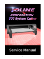
This is the first edition of the 300 System Service Manual. Subsequent updates or revisions will be announced on this page.
Copyright Notice
Copyright (c) 2001 Ioline Corporation
All Rights Reserved
Printed in the United States of America
P/N 107571
REV 0
April 2001
Trademarks
Ioline, System 300, and 301 Software are trademarks of the Ioline Corporation
All registered and unregistered trademarks mentioned in this publication are the sole property of
their respective owners.
Your Comments Are Requested
This manual is provided for informational purposes only. Ioline has made every effort to make the
system 300 easy to operate, maintain, and repair. The contents are subject to change without notice
and the Ioline Corporation assumes no responsibility for any errors that may be contained herein.
No part of this manual may be copied, disseminated, or distributed without the express written
consent of the Ioline Corporation.
Ioline Corporation values your comments on our equipment and documentation. Please send your
corrections or suggestions to:
Ioline Corporation
14140 NE 200th St.
Woodinville, WA. 98072
USA
ATTENTION: CUSTOMER SERVICE MANAGER
Or contact us by phone:
Phone: (425) 398-8282
FAX: (425) 398-8383
2
Table of Contents
Chapter 1 Introduction and Overview ............................................... 9
How To Use This Manual ..................................................................... 10
Safety ................................................................................................. 11
Warnings And Cautions ....................................................................... 11
Basic Safety Guidelines ........................................................................ 11
Product Overview ................................................................................ 12
Specifications ...................................................................................... 13
How The 300 System Works ................................................................ 13
Table Movement: ................................................................................ 14
Blade Movement: ................................................................................ 15
Limit Of Liability Statement .................................................................. 16
Ioline Warranty Policy .......................................................................... 16
Serial Number Identification ................................................................ 17
Glossary .............................................................................................. 17
Chapter 2 Nomenclature .................................................................. 18
Chapter 3 Setup & Operation ........................................................... 25
Keypad Controls .................................................................................. 26
Arrow Keys.......................................................................................... 26
Set Origin ........................................................................................... 27
Cutting Speed ..................................................................................... 27
Blade Force ........................................................................................ 27
Start/Stop ........................................................................................... 27
Power LED .......................................................................................... 27
Test Cut .............................................................................................. 28
Repeat ............................................................................................... 28
Software Installation ........................................................................... 29
Installing the 301, and Control Center Software ................................... 29
Windows 95/98/ME installation ............................................................ 30
Windows NT/2000 Installation.............................................................. 30
Installing the Hardlock Key .................................................................. 31
Using the 301 software ........................................................................ 32
3
Control Center Software ......................................................................
Screen Options ...................................................................................
Measurement Units .............................................................................
Acceleration ........................................................................................
Up/Down Delays .................................................................................
HPGL Default ......................................................................................
Send Settings to the 300 .....................................................................
Force ..................................................................................................
Panel Size ...........................................................................................
Scale ..................................................................................................
Blade Overcut .....................................................................................
Menu Bar Items ..................................................................................
File .....................................................................................................
Send Cut/Plot File................................................................................
Open Settings File ...............................................................................
Save Settings As... ..............................................................................
Setup .................................................................................................
Plotter Setup .......................................................................................
Com Port Setup...................................................................................
Display ...............................................................................................
Plotter Settings ...................................................................................
Factory Defaults ..................................................................................
ROM Version .......................................................................................
Memory Buffer ....................................................................................
Blade Holder Status.............................................................................
Motor Voltage .....................................................................................
Options ...............................................................................................
Filtering ..............................................................................................
HPGL Setting... ...................................................................................
Install New Firmware version ...............................................................
Calibration ..........................................................................................
Calibrate Plotter ..................................................................................
4
36
36
37
37
37
37
37
38
38
38
38
39
39
39
39
39
39
40
40
40
40
40
40
40
40
40
41
41
41
41
42
42
Test .................................................................................................... 42
Serial Test ........................................................................................... 42
Computer Port Test. ............................................................................ 42
Plotter Port Test................................................................................... 42
Help ................................................................................................... 43
Contents ............................................................................................. 43
About ................................................................................................. 43
Chapter 4 Troubleshooting and Testing .......................................... 44
Basic Operational Difficulties ................................................................ 45
Common Problems .............................................................................. 45
Error Messages ................................................................................... 46
Software Errors:.................................................................................. 46
L.E.D Codes ........................................................................................ 47
No Power When The 300 System is Turned On .....................................
The 300 Won’t Respond to the Computer .............................................
Communication Problems ....................................................................
Serial Communication Test: .................................................................
Testing the 300 Plotter Port: ................................................................
Testing the Computer Port: ..................................................................
Cutting Quality Problems .....................................................................
Mechanical, and Electronic Diagnostic Process .....................................
Expanded LED Codes ..........................................................................
External Inspection .............................................................................
Required Tools: ...................................................................................
Inspecting the Outside of the Unit: ......................................................
Internal Cabling and Connection Inspection .........................................
Tools Required: ...................................................................................
Initial Internal Inspection: ...................................................................
Testing the Power Supply ....................................................................
Tools Required: ...................................................................................
Inspecting the Fuse and Output Terminals: ..........................................
Testing the Power Supply Output Voltage: ...........................................
5
48
48
48
49
49
49
50
51
52
53
53
53
54
54
54
55
55
55
55
Reference Information for the Power Supply Test Fixture: .................... 56
Testing the Logic Board ....................................................................... 57
Tools Required: ................................................................................... 57
Testing the FETs (Transistors): ............................................................. 57
Testing and Replacing the Other Logic Components ............................. 58
Testing the Motors .............................................................................. 58
Tools Required: ................................................................................... 58
Initial Motor Inspection: ...................................................................... 58
Likely Modes of Motor Failure:.............................................................. 58
Tray (X Axis) Motor Replacement: ........................................................ 58
Carriage (Y Axis) Transmission ............................................................. 59
Carriage (Y Axis) Motor Replacement: .................................................. 59
Testing the New Motor: ....................................................................... 59
Contacting Ioline Customer Service ...................................................... 60
Diagnostic Record ............................................................................... 60
Re-Packing the 300 ............................................................................. 61
Chapter 5 Repair and Maintenance................................................. 62
List Of Recommended Tools And Equipment ........................................ 63
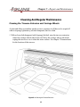
Cleaning And Regular Maintenance ..................................................... 64
Cleaning the Traverse Extrusion and Carriage Wheels ........................... 64
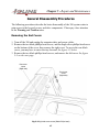
General Disassembly Procedures.......................................................... 65
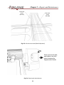
Removing the End Covers ................................................................... 65
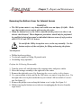
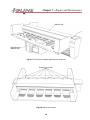
Removing the Bottom Cover for Internal Access ................................... 67
Tools Required: ................................................................................... 67
Y Axis Subsystem ................................................................................ 69
CARRIAGE .......................................................................................... 69
Carriage Replacement: ........................................................................ 69
Replacing the Carriage Ribbon Cable: .................................................. 70
Y Axis Transmission ............................................................................. 72
Y-Axis Transmission Replacement: ....................................................... 72
Y Axis Motor Replacement: .................................................................. 74
Y-Axis Belt Replacement: ..................................................................... 75
6
X Axis Subsystem ................................................................................ 77
X-Axis Transmission Assembly Replacement: ........................................ 77
X Axis Motor Replacement: .................................................................. 78
Table Assembly Replacement ............................................................... 79
Power Supply ...................................................................................... 82
Power Supply Replacement ................................................................. 82
Rear Panel Replacement .................................................................... 83
Electronic Sub-Systems ....................................................................... 84
Main Logic Board Replacement ............................................................ 84
Resetting the Factory Defaults ............................................................. 85
Keypad Replacement........................................................................... 85
Installing new Firmware ...................................................................... 86
Chapter 6 Drawings, and Bulletins .................................................. 87
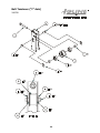
Belt Tensioner (“Y” Axis) ...................................................................... 88
Belt Tensioner (Bill of materials) ........................................................... 89
“Y” Axis Transmission .......................................................................... 90
“Y” axis Transmission (Bill of Materials) ................................................. 91
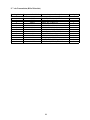
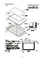
Table Assembly ................................................................................... 92
Table Assembly (Bill of Materials) ......................................................... 93
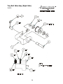
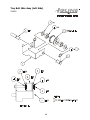
Tray Belt Idler Assy (Right Side) ........................................................... 94
Tray Belt Idler Assembly - Right side (Bill of Materials) .......................... 95
Tray Belt Idler Assy (Left Side) ............................................................. 96
Tray Belt Idler Assembly - Left Side (Bill of Materials) ............................ 97
Carriage Assembly ............................................................................... 98
Carriage Assembly (Bill of Materials) ..................................................... 99
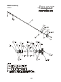
Shaft Assembly .................................................................................. 100
Shaft Assembly (Bill of Materials) ........................................................ 101
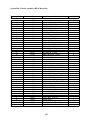
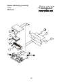
System 300 Chassis Assembly ............................................................. 102
System 300 - Chassis Assembly (Bill of Materials) ................................. 103
System 300 - Chassis Assembly (Bill of Materials) Cont... ...................... 104
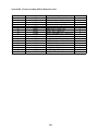
System 300 Wrapping Procedure ........................................................ 105
System 300 - Wrapping Procedure (Bill of Materials) ............................ 106
7
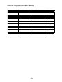
System 300 Boxing procedure ............................................................ 107
System 300 - Boxing Procedure (Bill of Materials) ................................ 108
Service Bulletins ................................................................................. 109
Installation Error/301 Software ........................................................... 109
Creating Barudin Files/301 Software ................................................... 110
Run Time Error Codes/301 Software ................................................... 110
Stitches Overlap to Wrong Side / 301 Software ................................... 110
How to “KISS-CUT” ............................................................................ 111
8
Chapter 1 Introduction and Overview
9
Chapter 1 - Introduction and Overview
Chapter One provides an overview of the Service Manual and important background
information about the 300 System Cutter. The following information is covered here:
•
•
•
•
•
•
•
How to Use This Manual
Safety
Product Overview
Limit of Liability Statement
Ioline Warranty Policy
Serial Number Identification
Glossary
How To Use This Manual
This Service Manual explains most aspects of the Ioline 300 System Cutter including
product specifications, installation directions, and testing and repair procedures.
Chapter 1 of the manual provides introductory information and general specifications.
Chapter 2 provides descriptive drawings showing part names for the 300 System
cutter. This section is intended to supplement the 300 System User’s Guide.
Chapter 3 familiarizes the user with how the 300 System operates and how to use
the software to maximum benefit. This section also supplements the 300 System
User’s Guide.
Chapter 4 is a troubleshooting and testing guide.
Chapter 5 provides details for repair and maintenance of the 300 System.
Appendix sections contain technical drawings and reference material.
10
Chapter 1 - Introduction and Overview
Safety
Warnings And Cautions
Please read the safety guidelines that are explained below before beginning the testing and replacement procedures explained in chapters 5 and 6.
WARNING
Warnings call attention to safety procedures that must be followed in
order to avoid potential personal injury.
Cautions call attention to procedures that are required to maximize
equipment performance.
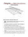
Basic Safety Guidelines
Comply with the following safety guidelines in order to prevent electrical shock and
other injuries.
• Only qualified service personnel should attempt any of the subsystem testing or
replacement procedures that are described in this manual.
• Unless otherwise noted, all subsystem testing or replacement procedures must be
performed with the 300 System turned off and the power cord removed from the
rear panel. This will avoid the possibility of electrical shock.
• Before beginning any subsystem testing or replacement procedure, make sure that
the 300 System is on a flat, stable, clean, and dry surface.
• Keep fingers, hair, and clothing well clear of the 300 System whenever moving
parts are being tested.
• When working on electronic components use a grounding wrist strap to prevent
electrostatic damage. If a wrist strap is not available Ioline can provide one.
11
Chapter 1 - Introduction and Overview
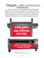
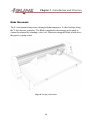
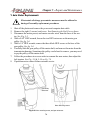
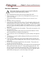
Product Overview
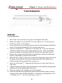
The Ioline 300 System Cutter can handle many different plotting, and cutting
operations up to 30 inches wide and 18 inches long. Three industry standard plotter
languages (HPGL 7475, HPGL 7596, and DMPL) are supported. It is most commonly used in conjunction with the Ioline 301 software for cutting applique patterns,
and producing embroidery stitch files for those appliques to be output to the most
common embroidery machines. The 300 System also comes with Control Center
software that allows adjustment of a variety of cutter settings from the computer.
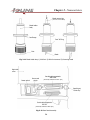
Figure 1-1. Ioline 300 System Cutter.
12
Chapter 1 - Introduction and Overview
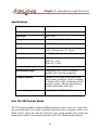
Specifications
Plotting Speed
24 in/second
Max Plotting Acceleration
1.0 g
Blade Force
10g to 700g
Cutting Area
18.25" x 30.25" (.463m x .768m)
Scale
1% to 999%
Pens / Tools
Accomodates Markers, Pens, Pencils to 22.2mm
(.875"). Minimum size: .30" (7.6mm)
Power Requirement
90-264 VAC, 47-66 Hz, 200 or 300 Watts
Overall Physical Dimensions
Height: 12" (.30m)
Width: 24" (.61m)
Depth: 45" (1.14m)
Shipping Weight
124 lbs (56 Kgs)
Environmental Range
Temperature: 0-35 C (32-95 F) Relative
Humidity: 30% 85% (Non-Condensing)
Hardware Interface
Standard RS-232C Serial interface:9600, Baud
rate, No parity, 8 Data bits, 1 stop bit Hardware
or Software (XON / XOFF) Handshaking, DB-25S
connector, requires. DB-25P mating connector.
Parallel communication: IEEE-1284
Command Languages
DM/PL, HP/GL: HP-7475 & HP-7596
How The 300 System Works
The 300 System combines media and Blade motion to create vector cuts. Vector files
are sent to the cutter via a serial or parallel connection with a computer or file server.
When a file is sent to the cutter the electronic logic system translates the vectors into
instructions for the X Axis (material motion) and Y Axis (Blade motion) motors.
13
Chapter 1 - Introduction and Overview
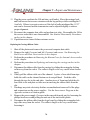
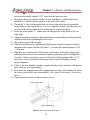
Table Movement:
Tray motion is accomplished by mounting the material to be cut on an adhesive sheet
that is mounted to a removable tray. The tray is then fastened to a fixed table on the
machine. The X-Axis transmission rotates a shaft which in turn rotates a gear assembly.
Belts on the right and left underside of the fixed table wraps around the gear assembly
which in turn moves the fixed table in and out.
Fig. 1-2 Table (X Axis) Motion
14
Chapter 1 - Introduction and Overview
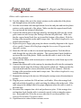
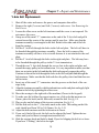
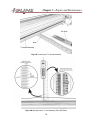
Blade Movement:
The Y-Axis transmission powers a timing belt that transports a V wheel carriage along
the Y-Axis traverse extrusion. The Blade is attached to the carriage and is made to
contact the material by actuating a voice coil. When not cutting the Blade is held above
the paper by spring action.
Fig. 1-3 Carriage (Y Axis) Motion
15
Chapter 1 - Introduction and Overview
Limit Of Liability Statement
It is the responsibility of the operator to monitor the performance of the 300 system
and maintain it in proper working condition by following the operating and regular
maintenance instructions. It is also the responsibility of the operator to follow all
safety precautions and warnings that are described in this manual. Ioline is not responsible for injuries that may occur as a result of unsafe operating procedures or for degraded performances as a result of failure to maintain the 300 System.
This Service Manual is provided for informational purposes only. The contents are subject to change without notice and Ioline Corporation assumes no
responsibility for any errors that may be contained herein. No part of this
Service Manual may be copied, disseminated, or distributed without the express written consent of Ioline Corporation.
Ioline Warranty Policy
Ioline Corporation provides a 12 month parts and labor warranty on all new equipment
and 90 days on repaired units, unless specifically noted otherwise. Every unit is recorded by serial number when it leaves the factory. The warranty period is based on
the serial number of the unit and extends from the date of manufacture up to 12
months, plus an extra 3 months for self life. Making the total warranty period 15
months from the date of manufacture. See Fig. 1-4 on page 17 for an explanation of
how to read the serial number of the machine.
For warranty service, the end user must work through their dealer. Ioline Customer
Service is available to assist Authorized Dealers in the performance of their equipment
support.
16
Chapter 1 - Introduction and Overview
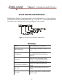
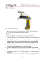
Serial Number Identification
Identification of Ioline Corporation products is accomplished by use of a serial number located on the back of the plotter (See fig. 2-2 on Pg 17). You can determine the
model and date of manufacture by interpreting this serial number.
Figure 1-4. Ioline Serial Number Indications.
Glossary
1. BOM
Bill(s) of materials for an assembly
2. BOTTOM PAN
Metal housing protecting the underside of the
cutter.
3. CARRIAGE
The component that holds the knife. It
travels along the Y- Axis on the traverse
assembly.
4. KEYPAD
Where the user controls simple plotter
functions. Carriage and media motion is
accessible from here during stop mode.
5. TRAVERSE ASSEMBLY
Structure that supports and guides the
carriage.
6. X- AXIS
Direction of tray moving in and out of the
machine.
7. Y- AXIS
Direction of knife motion. Usually associated
with the carriage.
17
Chapter 2 Nomenclature
18
Chapter 2 - Nomenclature
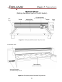
Nomenclature
(Defining the different parts of the 300 System)
Carriage Assembly
Left
Cover
Traverse
Adhesive Sheet
(See detailed drawing on Pg. 20)
Keypad
(On Removable Tray)
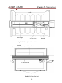
Figure 2-1. 300 System (With Removable Tray) Front View
Serial Number Plate
Table Assembly
(Without Removable Tray)
Rear Panel Assembly
(See Detailed drawing on Pg. 21)
Figure 2-2. 300 System (Without Removable Tray) Rear View
19
Right
Cover
Chapter 2 - Nomenclature
Front
Logic Board
Power Supply
(See Detail Below)
“X” Axis Motor
Assembly
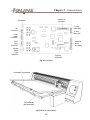
Fig 2-3 300 Cutter (Bottom View with bottom cover removed)
Tray strip
(Keeps the removable tray down)
Adhesive Sheet
“Y” Axis drive belt
Removable tray thumb screws
Fig 2-4 300 Cutter (Top View)
20
Chapter 2 - Nomenclature
“X” Axis Transmission
Assembly
Keypad Assembly
Right End Plate
“Y” Axis
Transmission
Assembly
Rear Panel
Assembly
(See detailed drawing on Pg. 21)
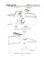
Fig. 2-5 300 Cutter (Right view with cover removed)
Belt Tensioner
Assembly
Left End Plate
Fig. 2-6 300 Cutter (Left view with cover removed)
21
Chapter 2 - Nomenclature
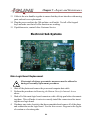
Parallel Port
Connection
5v Regulator
“Y” Axis
Motor ENC
Fan
Connectors
“X” Axis
Motor ENC
Power
Supply
Connection
Servo
Motor
Connection
Keypad &
Serial
Connection
Carriage
Ribbon
Cable
Connection
Programmable ROM
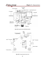
Fig. 2-7 Logic Board
Removable Tray Assembly
Table Assembly
(Non-Removable)
Fig. 2-8 Tray & Table Assembly
22
Chapter 2 - Nomenclature
Voice-coil Wires
Top Spring
Wheel
Main Voice-coil
Secondary Voice-coil
“Y” Axis Belt
“Y” Axis Belt
Blade holder
thumb screw
Blade holder
Sensor
Blade Holder
Blade Jaw
(See detailed drawing
on Pg. 21)
Fig. 2-9 Carriage Assembly (With Blade installed)
Top Traverse Wheel
(Spring Loaded)
Flex
Cable
socket
Carriage PCB
Belt “T” Connector
Belt “T” Connector
Traverse Wheel
Traverse Wheel
Fig. 2-10 Carriage Assembly (Rear View)
23
Chapter 2 - Nomenclature
Blade removal pin
(Push to remove blade)
Blade holder
body
Jaw Flange
Foot “O” Ring
Foot
Blade
Fig. 2-11 Blade Holder Assy 1) With foot 2) With foot removed 3) Removing blade
Right side
cover
Power switch
Power cord
plug in
Parallel cable receptacle
IEEE-1284
(Commonly called the “Printer” port)
Parallel port
“Cable Clip”
Serial cable receptacle
RS-232
(Commonly called the “COM” port)
Fig. 2-12 Rear Panel Assembly
24
Chapter 3 Setup & Operation
25
Chapter 3 - Setup & Operation
This section contains guidelines for basic operation of the 300 System Cutter. The
following primary topics are explained and illustrated:
•
•
•
•
•
300 Keypad Controls
301 Software Screen Options
301 Software Menu Items
Control Center Screen Options
Control Center Menu Items
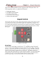
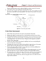
Keypad Controls
The keypad on the 300 provides control of the motion systems on the cutter as well as
access to speed, and force control. Blade depth can be adjusted by using the “TestCut” button, and repeatability is performed by pressing the repeat button. Communication can also be interrupted and restored and the initial plotting point can be set from
the keypad.
Test Cut
Repeat Start/Stop
Fig. 3-1 The 300 Keypad
Arrow Keys
The arrow keys control paper (vertical arrows “X”) and Blade carriage (horizontal
arrows “Y”) movement within the parameters of the 300’s frame setting. The plotter
must be in stop mode (red LED) to use the keypad arrow keys. The Blade and media
speeds become greater the longer the key is depressed. The Blade carriage has a
safety feature that will not allow it to collide with the end plates. The tray will not allow
forward motion outside of the frame during cutting operations. Diagonal motion is
possible by pressing a vertical and horizontal arrow key simultaneously.
26
Chapter 3 - Setup & Operation
Set Origin
You have to set an origin point before sending a cut file to the 300. When the Set Origin key is pressed the plotter logic will use the current X-Axis position of the tray, and
Y-Axis position of the Blade carriage as the starting point of the next plot. When the
Set Origin key is pressed the LED will turn green and the 300 will accept a plot file.
Cutting Speed
You can set the speed of cutting by adjusting the knob on the keypad. If the knob is
put in the “Minimum” position (6:00), this puts the cutter in “Crawl Mode” which
allows the blade to move very slowly for precise positioning. Different materials require
different speeds for cutting accuracy, and correct depth. For more information, see
Chapter 4: Cutting quality problems.
Blade Force
You can set the Blade force by using the knob on the keypad. The minimum value (10
Grams) and maximum value (175 Grams) of the available force can be set from the 300
Control Center if you are plotting with a pen. If you are using a blade, then the force is
set at 700 grams, and is not adjustable from the control center software. Material type
and thickness determines the correct force setting range on the keypad force knob.
Start/Stop
The Start/Stop key controls serial or parallel communication between the plotter and
the computer. When the communication line is open the LED will be green (Start
mode). The LED turns red when communication is stopped (Stop mode). Plot files,
and Control Center settings can only be sent to the cutter when communication line is
open (green LED).
Power LED
The light emitting diode (LED) immediately above the Start/Stop switch indicates the
state of communication and provides error codes. LED error codes can be found in
Chapter 4 in the LED Codes section. The LED is red after power is turned on and the
carriage resets. A red LED also indicates that the communication line is interrupted
between the cutter and the computer. When communication is open between the cutter
and the computer the LED will be green.
27
Chapter 3 - Setup & Operation
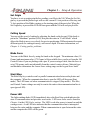
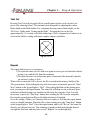
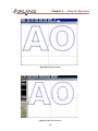
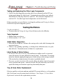
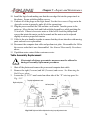
Test Cut
Pressing Test Cut on the keypad will cut a small square with a circle cut into 4 pie
pieces (See drawing below). This internal cut is designed for adjusting the correct
blade depth on the blade holder. For a diagram showing correct blade depth, see the
300 User’s Guide under “Setting up the blade”. Pressing the test cut key for
approximatelly 2-3 seconds will cut the Ioline logo. This is designed as a further test to
see how the blade is cutting with more complex shapes, and letters.
Fig. 3-2 Test Cut
Repeat
The repeat button serves two purposes.
1) To repeat the same cut over and over again on a new piece of material without
having to re-send the file from the computer.
2) To repeat the same cut on the same piece of material if the material is hard to
cut such as Leather, or Felt.
When a file is sent to the 300 to be cut, the file is stored in the memory buffer of the
300 system cutter. After loading the tray with a new piece of material, press the “Start/
Stop” button so the keypad light is “Red”. After setting the blade in the starting position, you can press the repeat button. The same file will then cut out on the new piece
of material without having to re-send the cut file from the computer. Note: It is only
neccessary to press the “Star/Stop” button after sending the file from the computer.
Pressing the repeat button will leave the light red when it is finished.
If you are cutting “Hard to cut” material such as Leather, or Felt then the repeat button
serves a valuable function. When the file is done cutting, press the “Start/Stop” button
so the keypad light is “Red”. Press the repeat button, and it will “Re-cut” the same file
directly over the previous cut. This technique is good for thick material that doesn’t
cut right the first time, and may take several “Repeats” to cut through fully.
28
Chapter 3 - Setup & Operation
Software Installation
The Ioline 301 Embroidery software is a Microsoft Windows 95/98/ME/2000 compatible program that
comes on a CD ROM disk with the cutter or is available online at www.ioline.com. A Macintosh version of
the 301 software is not available. The 301 software will perform the following:
1.Import some of the most popular embroidery files including Tajima, Toyota, PLT, DXF, and Baraudan.
2. Export in some of the most popular file formats like Tajima, Toyota, PLT, DXF, and Baraudan.
3.Cut out multiple appliques in multiple layers.
4.Create multiple stitch files in multiple layers.
5.Stitch editor program for editing all facets of a stitch.
6.Design Setup window for easy shape duplication, rotation, and layer selection.
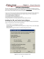
Installing the 301, and Control Center Software
The 301 software can use either a mouse or the keyboard of the computer to change the default plotter
settings. If using the keyboard, note the following guidelines:
·
·
·
Use the Tab key to cycle through the screen fields.
Use the up/down cursor movement or numeric keypad keys to change a numeric value within a highlighted menu field.
Use the Alt key to toggle between the screen fields and the pull down menus.
Fig. 3-3 301 and Control Center installation screen
29
Chapter 3 - Setup & Operation
·
Use the Enter key to select a highlighted field when a pull down menu is open.
Windows 95/98/ME installation
1. Place the disk in your CD ROM drive.
2. The CD should Autorun once it is placed in the drive, and the drive door is closed.
The install wizard will now start the installation process. Follow the prompts until the installation of the Ioline
301 and Control Center software is finished (See Fig. 3-2 on the previous page).
3. If the CD does not Autorun, click on the “Start” button and then “Run”.
4. In the Run window click on “Browse”, and select your CD ROM drive in the box labeled “Look in”.
5. Select the file “IOSETUP.EXE”, and click “OK”.
6. In the Run box, click “OK”.
The install wizard will now start the installation process. Follow the prompts until the installation of the Ioline
Control center is finished.
Windows NT/2000 Installation
Installation of the CD ROM is the same for Windows NT/2000 as for Windows 95/98/ME. The difference
is in the “Hardlock Driver” (See the next section “Installing the Hardlock”). Windows 95/98/ME uses a
different hardlock driver that will not work with Windows NT/2000. To obtain this driver go to
www.ealaddin.com/hardlock/downloads.asp and download the file “HLDRV32.EXE”. This file is a self
extracting file, so when the download is complete, “Run...” the file from the Run dialog box. After installation
is complete, you can use the 301 software in Windows NT/2000. If you can not obtain this driver over the
internet, contact Ioline Tech Support for a disk, or e-mailed file.
30
Chapter 3 - Setup & Operation
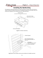
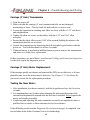
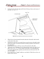
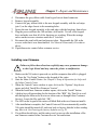
Installing the Hardlock Key
The Hardlock key is a device that allows you to use the 301 software (A common name for this device is a
“Dongle”). Without it, the software will not work. The Hardlock key comes with the 300 system cutter in the
accessory kit, and plugs into your computers printer port. (See drawing below)
Directional Arrow
(This shows the end to plug into the printer port)
Printer Pass-Through
(Allows the printer to be used)
Printer port Receptacle
Fig. 3-4 301 Software Hardlock Key
Back of computer
Ioline 301 Hardlock “Dongle”
(Be sure to plug in the arrow side to the
printer port)
Printer Cable
(If you have a printer, or another
Dongle you can plug it into the
other end of the Hardlock)
Fig. 3-5 Rear view of computer showing correct installation of the Hardlock and printer
31
Chapter 3 - Setup & Operation
Using the 301 software
The 301 software is very easy to use, and anyone can learn to use it in just a few minutes. The first thing to
remember is that the 301 software is a tool to help you cut appliques, and create stitches for those pieces. It is
not an “Automatic” process, so some learning on your behalf is required. The 301 software uses many different
input file types such as Tajima (.DST), Melco (.EXP), Toyota (.10o), Barudan (.DAT), Autocad (.DXF), and Hewlet
Packard (.PLT). These files can contain plot and stitch coordinates at the same time allowing you to create a
stitch disk from another embroidery software package. The 301 software can import the file, and cut the applique piece or pieces out, while keeping the stitch file intact for your embroidery machine to sew.
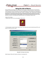
Using the 301 software
1. Double click on the “301” icon on the desktop. (Seen below)
2. The first window to open is the main import screen. This window allows you to choose the type of file, and
location of the file you wish to open.
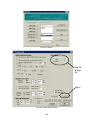
Fig. 3-6 301 Software Main Window
Select the type of file, and it’s location, and click on “Load import file”.
32
Chapter 3 - Setup & Operation
Fig. 3-7 301 design view
Zoom Function
Choose whether to display the cut file, or the stitch file
In stitch display mode, clicking on “Single Step” shows the order that the embroidery machine will stitch the
file
“Design setup” allows the user to change certain parameters of the cut file. It also allows easy changing of
the layers. (See detail on Pg. 34)
Sends the file to be cut
Saves the stitch file for your embroidery machine to sew
“Create Stitches” allows the user to create stitches, and modify them to the users liking.
(See detail on Pg. 34)
Prints the current view to a standard Windows printer
If you are cutting out a DXF file, this option allows the user to rescale the file to work better in the 301
software. Also you can choose to use the mouse button to “Pan” the drawing
“Port Setup” allows the user to change the port the cutter is plugged into
“Edit Design” allows the user to edit the stitches manually, to fix problems (See detail on Pg. 35)
Help using the 301 software
Close the design view
Fig. 3-8 301 Display Options buttons defined
33
Chapter 3 - Setup & Operation
Color Setup
Allows the user to work
on individual layers, and
create a different stitch
file for each layer. Or
work on all the layers and
create stitches for all the
layers at once.
Adjust Imported Design
Allows the user to adjust
Rotation, Mirror, and units
of measure for the design
Margins and Copies
Allows the user to easily
duplicate a single shape to
fill the tray of fabric
K-C ALL
This is a specialty function for
“KISS-Cutting”. Turn K-C ALL on
if you intend to cut multiple
layers that must be on top of
one another after cut.
Material Dimensions
Allows the user to change the
dimensions of the fabric to be
cut.
Cutter Size
Allows the user to change easily back
and forth from 18”x24” and 18”x30”
Fig. 3-9 Design setup window
Outline Running Stitch
Makes an outline around the
letter or shape for accurate
placement on the garment
Zig Zag Column Stitch
Creates a zig zag stitch
around the letter or
shape. Allows easy
adjustablity of the stitch to
accommodate many
embroidery styles
Tackdown Running Stitch
Makes a stitch that is indented on
the fabric to “Tack-Down” the
letter or shape to the garment
before applying the Zig Zag, or
Satin stitch
Satin Column Stitch
Extra filtering for troublesome
stitches
Creates a satin stitch
around the letter or
shape. Allows easy
adjustability of the stitch
to accommodate many
embroidery styles
Fig. 3-10 Create Stitches Window (See below for the four types of stitches)
Fig. 3-11 1) Placement Stitch 2) Tackdown Stitch 3) Zig Zag Stitch 4) Satin Stitch
34
Chapter 3 - Setup & Operation
Fig. 3-12 Edit Design Window
Fig. 3-13 Edit Stitches Window
35
Chapter 3 - Setup & Operation
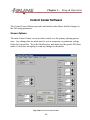
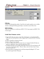
Control Center Software
The Control Center Software provides and interface that allows detailed changes to
the 300 cutting parameters.
Screen Options
The main Control Center screen provides control over the primary plotting parameters. Any changes that are made must be sent as temporary or permanent settings
before they take affect. Press the Start/Stop key and make sure the green LED (Start
mode) is on before attempting to send any changes to the plotter.
Fig. 3-14 Ioline Control Center Window
36
Chapter 3 - Setup & Operation
Measurement Units
English or Metric unit systems may be used for length and speed settings.
Acceleration
The acceleration setting determines how quickly the blade will change speed when
starting or ending a line. The factory default acceleration setting is 1.0 g (1 g = 32.2 ft/
s2). The setting range is 0.1 to 1.0 g.
Up/Down Delays
Up/down delay controls how long the blade hesitates when actuated. Zero delay
makes the blade rise instantly when line drawing is finished. By default it takes the
blade 6 milliseconds to lower onto the paper when the logic powers the voice coil.
Longer blade delay settings make the Blade move more slowly but may improve the
quality of the cut line. The setting range is 0 to 250 ms (milliseconds).
HPGL Default
Your 300 cutter supports three industry standard plotter languages; HPGL 7475,
HPGL 7596, and DMPL. Your 300 will automatically switch between DMPL and
HPGL. The plotter cannot distinguish between HPGL 7475 and HPGL 7596 so the
version number must be set in Control Center before a plot file is sent.
HPGL stands for Hewlett Packard Graphics Language and DMPL stand for Digital
Microprocessor Plotter Language. HPGL 7475 is the default plotting language and is
most common in the industry. It has a lower left origin which means the 300 begins
plotting from the lower left (keypad side) and measures everything from this location.
HPGL 7596 uses a center origin and is much less common. A center origin means the
300 begins cutting from the center of the panel and measures everything from this
location.
Send Settings to the 300
When changes are made in the screen dialog boxes the plotter logic has to be updated
via the serial, or parallel link. Three options exist to make the changes take effect.
Sending the settings with the Temporary button will replace the current plotter parameters until the power is turned off or new settings are sent from the control center. If
the Permanent button is used to send the settings they remain in the plotter (even after
the power is turned off) until they are changed from the Control Center. The update
Display button displays the “Current” status of the cutter. If your unsure about the
settings currently setup on the plotter, pressing the Update Display button will show
you what they are.
37
Chapter 3 - Setup & Operation
Force
The Force settings control in the 300 Control Center is not adjustable when you are
using a Blade. The ability to cut fabric takes a lot of grams of force, and therefore does
not need adjusting.
Panel Size
The default panel size for the 300 System is 18.25” long by 32.25” wide. This size is
the cutting area of the 300 cutter, and can not be set any bigger than the default size.
Scale
By default the 300 will produce a cut at 100% the size of the specified in the plot file
(no scaling). If the X and Y scale is set to 50% the 300 will produce an applique that is
half the specified size. You can set either or both the X and Y scaling of the plot from
1% to 999%.
Blade Overcut
Because of the angle of the blade, the machine must perform an Overcut to meet up
with another line. If you picture dragging a stick in the sand behind you, the angle of
the stick is the angle of the blade. Your body represents the center (or pivot) point of
the blade, and the tip of the stick represents the tip of the blade. If you draw a box in
the sand with your feet, it will look fine. But if you draw the same box with the stick
behind you, the corners will be rounded. This is where the overcut comes in. It extends
the tip of the blade past the corner point so it makes the corners square instead of
rounded.
Blade Steering Arc
The blade steering arc is simply the rotational angle of the blade around a corner. If the
blade is cutting a box, each corner is a 90 degree angle. In order for the angle to be cut
right by an angled blade, the machine must perform a rotation around the 90 degree
angle for it to look good. Typically the Blade Steering Arc is 30 degrees for a 45 degree blade, and 15 degrees for a 60 degree blade. These are good standards for cutting
out most materials.
38
Chapter 3 - Setup & Operation
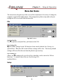
Menu Bar Items
The menu items along the top of the screen allow adjustment of a variety of settings for
computer control of the Ioline plotter. File management, plotter setup and serial port
testing can all be accessed from the menu bar.
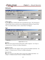
File
Fig. 3-15 File Menu
Send Cut/Plot File
Use this option to send plot files (.plt format) to the 300.
Open Settings File
Opens custom settings for the 300 that have been stored with the Save Settings As...
option below. When the 300 is shut off these settings will be lost. The factory default
settings will be in effect the next time the plotter is powered up.
Save Settings As...
Allows custom settings to be saved to a file so that they can be sent to the 300 at a
later time. To retrieve these files use Send Settings File
explained above.
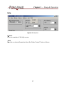
Setup
Figure 3-16 Setup Menu
39
Chapter 3 - Setup & Operation
Plotter Setup
Allows selection of the plotter model and COM port.
Com Port Setup
Provides a list of COM ports to select from.
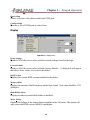
Display
Figure 3-17 Display Menu.
Plotter Settings
Replaces all of the screen values with the current settings stored in the logic.
Factory Defaults
Replaces all of the screen values with the factory defaults. A dialog box will appear
that allows these values to be sent to the plotter.
ROM Version
Displays the current ROM version installed in the plotter.
Memory Buffer
Displays the amount of buffer memory on the logic board. This value should be 12 K
(kilobytes)
Blade Holder Status
Displays weather or not the blade holder is installed.
Motor Voltage
Displays the voltage of the motors that are installed in the 300 cutter. This option will
only work with ROM version 106882 r0 and higher.
40
Chapter 3 - Setup & Operation
Options
Figure 3-18 Options Menu
Filtering
Displays the filtering dialog window. Some files don’t produce quality curves, and line
structure, enabling the filtering option helps to smooth out some of these lines.
HPGL Setting...
Allows the 300 cutter to switch between HPGL/7475 (Corner origin), and HPGL/7596
(Center origin).
Install New Firmware version
1) Copy the file that was sent to you by Ioline Tech Support or downloaded off the
Ioline web site to the hard drive of the computer that is connected to the 300 System
Cutter.
2) Click on “Install New Firmware Version”.
3) Click on “Begin Version Install”.
4) The next window shows the file structure on your computer. Find the file that was
sent to you (.BIN file). Click on the file, and click on “OK”.
5) The plotter will make a beep sound, and the light will turn off. The new firmware will
now start to load into the plotter. When it’s done, close the Ioline Control Center,
and turn the plotter off.
6) Reset the plotter by turnning it back on while pressing and holding the “UP” arrow
key on the keypad of the 300 System.
41
Chapter 3 - Setup & Operation
Calibration
Figure 3-19 Options Menu
Calibrate Plotter
Provides methods to calibrate the cutter for maximum accuracy. The 300 System is
calibrated at the factory, and does not need dimensional calibration. If you feel the
cutter is not dimensionally accurate, contact Ioline Tech Support.
Test
Figure 3-20 Options Menu
Serial Test
Tests the serial connection between the plotter and the computer. See Chapter 4,
Communications Problems for further information.
Computer Port Test.
Tests the serial port on the computer with a special tool available from Ioline. See
Chapter 4, Communications Problems for further information.
Plotter Port Test.
Tests the serial port on the plotter with a special tool available from Ioline. See
Chapter 4, Communications Problems for further information.
42
Chapter 3 - Setup & Operation
Help
Figure 3-21 Help Menu
Contents
Lists the contents of the help screen.
About
Provides revision information about the Ioline Control Center software.
43
Chapter 4 Troubleshooting and Testing
44
Chapter 4 - Troubleshooting and Testing
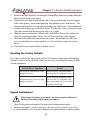
This section contains guidelines and testing procedures for resolving most cutting
difficulties. Some of this information coincides with repair procedures located in
Chapter 5. The following primary topics are explained and illustrated:
• Basic Operational Difficulties
• Mechanical, Electrical, and Electronic Diagnostic Processes
• Contacting Ioline Customer Service
Basic Operational Difficulties
If the system isn’t working correctly it is very important to determine which component is causing the problem. Likely difficulties may involve the computer, the power
cord, parallel or serial cable, the design software, or the 300. If the problem appears to
be with the computer or design software consult the appropriate documentation or an
Ioline dealer first.
The information in the following sections has been organized to eliminate minor
problems with easy solutions first. If these remedies do not fix the problem more
complex and invasive resolutions are provided. If a solution cannot be found in this
manual or by changing the software and computer setup, fill out the Diagnostic
Record at the end of this chapter and contact Ioline customer service.
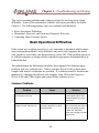
Common Problems
Problem
Cause
Solution
The cut file doesn't start in the
correct place on the tray.
The "Origin" has not been set.
Press the "Set Origin" button
on the keypad with the knife
positioned where the cut file
should start.
A file has been sent from the
software, but the 300 won't cut.
A communication problem has
occurred or the 300 is in "Stop"
mode (Red LED).
Make sure the serial or parallel
ports on the computer and the
300 are configured properly.
Or press the "Start/Stop"
button on the keypad to obtain
a Green LED.
45
Chapter 4 - Troubleshooting and Testing
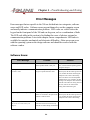
Error Messages
Error messages that are specific to the 300 are divided into two categories; software
errors and LED codes. Software errors present themselves on the computer screen
and usually indicate a communication problem. LED codes are visible below the
keypad on the front panel of the 300 and can be green, red or a combination of both.
The LED code table in this section is for finding the cause of obvious external or
communication problems. Later in the chapter a more comprehensive LED index is
available for complex mechanical and electronic difficulties. Other errors can occur
with the operating system or the design software and should be resolved with the
software vendor.
Software Errors:
Error Message
Problem
Solution
Could not open COMx or LPTx
The software could not locate the cutter Verify the cutter is connected to that
on the specified COM or LPT port.
port, or check that the operating system
recognizes the port.
Green light not on or cutter not connected The software opened the port but could Be sure the cutter is connected to the
to COMx or LPTx
not get a response from the cutter.
selected port, that the cutters green LED
is on, and that the cable connecting the
computer to the cutter is functioning.
Due to the nature of serial and parallel
communication, it is possible to get this
message if an attempt is made to interact
with the cutter while it's cutting. If this is
the case, wait for the 300 to finish
cutting and send the file again.
Setup COM port and check plotter present. The last operation requires that the
Be sure the cutter is connected to the
plotter be connected to the port but the selected port, that the cutters green LED
software could not find it.
is on, and that the cable connecting the
computer to the cutter is functioning.
The plotter that you selected is not the
same as the one connected to your
computer.
The Control Center cannot match the
Select the correct plotter from the list.
cutter that was chosen at the start up
with the one found during initialization.
46
Chapter 4 - Troubleshooting and Testing
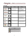
L.E.D Codes
LED Sequence
Problem
1. Buffer Overflow
3+ Second
pause then
repeat
2. Communication Problems
3. Defective RS-232 Chip.
Outdated Firmware.
3+ Second
pause then
repeat
Solution
1. Perform cutter reset.as outlined
later in this chapter.
2. Perform communication test as
outlined later in this chapter.
3. Replace the RS-232 chip.
Check the Firmware version, install
firmware if needed. Contact Ioline
Tech Support
Plotter Language syntax error
The file being sent to the cutter is not
of the same language that the cutter
is looking for. Open the Ioline Control
Center, and run a test file. If the error
doesn't happen again, check the
original file for problems.
Carriage ("Y" axis) jam.
Check to make sure the carriage
moves side to side freely, and
remove all objects causing the jam to
occur.
Table ("X" Axis) jam
Chack to make sure the tray moves
in and out freely, and remove any
objects causing the jam to occur.
Logic Board Error
Call Customer Service
Constantly
Repeating
3+ Second
pause then
repeat
3+ Second
pause then
repeat
2 Red Flash
2 Green Flash
repeat
Le ge nd
Solid GREEN Light Emitting Diode (LED)on the keypad
Blinking GREEN Light Emitting Diode (LED) on the keypad
Blinking RED Light Emitting Diode (LED) on the keypad
47
Chapter 4 - Troubleshooting and Testing
No Power When The 300 System is Turned On
If the 300 does not initialize or the fan does not spin when the power is turned on there
are a few simple steps to follow to determine if a serious problem has occurred.
1.
2.
Check the power cord. Make sure that it is firmly plugged into the wall and into
the back of the plotter.
Check the voltage at the wall outlet and verify that it is within the operating
limits as specified in Chapter 1, Specifications.
If there are no problems with the power to the 300 System proceed to the Mechanical,
Electrical, and Electronic Diagnostic Process later in this chapter.
The 300 Won’t Respond to the Computer
If there is a problem getting the 300 to accept commands from the computer, perform
these procedures:
• Verify that the communications cable is correctly connected to the plotter and to
the proper communications port on the computer.
• Check to see that the computer LPT, or COM port that is being used is configured
to match the 300’s serial, or parallel port settings.
• Χψχλε τηε ποωερ οφφ ανδ ον αγαιν το ρεσετ τηε χοµµυνιχατιον πορτσ
ον τηε 300 σψστεµ.
• Make certain that the file and the 300 are set to the same plotter language.
• If the connection is good and the port assignments appear to be correct, proceed to
the next section.
Communication Problems
Many plotting problems can be resolved by testing and adjusting the communications
between the plotter and the computer. There are three diagnostic tests that can be run
from the 300 Control Center. These tests are designed to help determine if there are
communications problems and isolate where the difficulty is occurring.
The last two tests require a diagnostic module (available from an Ioline dealer) connected to the serial port on the computer or the 300. If the following tests do not resolve the problem and the computer and software are working properly, proceed to the
Mechanical/ Electrical Diagnostic Process later in this chapter.
48
Chapter 4 - Troubleshooting and Testing
Serial Communication Test:
Run this test from the 300 Control Center. The diagnostic module will NOT be needed
to run this test.
1.
2.
3.
4.
5.
6.
7.
8.
9.
Connect the serial ports on the 300 and the computer with a serial cable.
From the 300 Control Center screen, select Test.
Select Serial Test.
Turn on the 300 while holding down the Test cut key on the keypad until the 300
beeps and the LEDs flash three times.
Press the Start/Stop key on the keypad to verify that the handshake line (CTS),
displayed on the computer, toggles ON and OFF. Leave the handshake lines ON.
Press the Repeat key to switch the 300 into ECHO mode. The green LED will
come on.
Press any key on the computer and verify that the character transmitted equals
the character received. If the 300 and the computer pass all these tests there
should not be any problems producing appliques from plot files.
Select Exit after completing the serial test.
Turn off the 300 at the end of the test. Normal communications will be restored
when the power is turned back on.
If this test is successful the next two tests are not necessary.
Testing the 300 Plotter Port:
Run this test from the 300 Control Center. The diagnostic module WILL be needed to
run this test.
1. Connect the diagnostic module directly to the 300 serial port.
2. Turn on the 300 while holding down the Test Cut key on the keypad. Hold down
the Test Cut key until the 300 beeps and LEDs flash three times.
3. Press any arrow key to transmit and receive characters. Verify the 300 beeps and
the green LED flashes.
4. Turn off the 300 at the end of the test. Normal communications will be restored
when the power is turned back on.
Testing the Computer Port:
Run this test from the 300 Control Center. The diagnostic module WILL be needed to
run this test.
49
Chapter 4 - Troubleshooting and Testing
1. Connect the diagnostic module directly to the serial port on the computer.
2. From the 300 Control Center, select Test.
3. Select Computer Port Test.
4. Verify that the COM port displayed is the correct one. If it is not, press the ESC
key twice and select the correct COM port from the Setup, COM Port Setup
menu. If any key other than ESC is pressed the computer serial test screen will
be displayed.
5. Press any key on the computer keyboard and verify that the character transmitted
is the same as the character received.
Cutting Quality Problems
Good cutting quality is dependent upon a number of different factors. The type of
material, environmental conditions, and operator habits are only a few of the variables
that can affect the quality of a cut. It is important that the 300 is loaded and maintained
according to the guidelines in the 300 User’s Guide and in Chapters 2 and 5 of this
manual. The table below is a summary of the most common difficulties:
Problem
Cause
Solution
If a cut file has been sent, and the output is The file was sent with the wrong plotter Make sure the file was created with the
erratic.
language setting.
correct plotter language, or the cutter,
and the Ioline Control Center are setup
correctly.
If the corners of lines on the completed
1. Knife Offset is not set correctly
1. Knife offset can be changed in the
applique are not completelly meeting.
Ioline Control Center. See Chapter 3
setup & operation of Ioline Control
Center
2. Knife overcut is set too low.
2. Overcut should be set to 20 for
standard twill
3. Loose set screw, or loose belt on 3. See chapter 5 for procedures on
the cutter.
how to fix a loose setscrew, or belt.
If a cut file has been sent, and the output is The cut file has too many "Nodes" in If you are using Corel Trace to
VERY slow no matter how fast the speed is it.
create applique files, the output will
set.
take a long time, and won't cut very
nice. Instead, hand trace the file to
reduce the amount of Nodes in the
file.
Common Cut Quality Problems
50
Chapter 4 - Troubleshooting and Testing
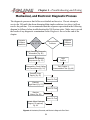
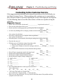
Mechanical, and Electronic Diagnostic Process
The diagnostic processes that follow are detailed and invasive. Do not attempt to
service the 300 until it has been determined that simpler solutions (see above) will not
resolve the problem. It is recommended that the sequence represented in the following
diagram be followed when troubleshooting the 300 System cutter. Make sure to record
the results of any diagnostic examination on the Diagnostic Record at the end of the
chapter.
Computer
Software
Resolution
LED Codes
(Pg. 47, 52)
Communication
Problems
Computer
Software
Resolution
Begin Recording Diagnostic
Information (Pg. 60)
Examine The External
Components (Pg. 53)
Logic
Problem
Disassemble, Check Cabling
and Connections (Pg. 54)
Test, Chapter 4
Communicationl Test (Pg. 48)
Examine Power
Supply (Pg. 55)
Power On Test
Examine
Logic Board (Pg. 57)
Power On Test
Examine
Motors (Pg. 58)
Power On Test
Contact Ioline Customer
Support (If required)
Pg. 60
Figure 4-1. Mechanical, Electrical, and Electronic Diagnostic Flow Chart.
51
Chapter 4 - Troubleshooting and Testing
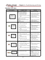
Expanded LED Codes
LED Sequence
Dark or
erratic
flashing LED
Probable Cause
300 System not plugged in
Cycling power supply due to:
Incorrect power supply or
defective power supply
Defective transistor(s) on the logic
board
Short or other problem with motor
Defective power supply
Defective transistor(s) on the logic
board
Defective keypad
Carriage ("Y" Axis) jam due to:
Media or mechanical jam
3+ Second
pause then
repeat
Transmission failure
Defective power supply
Defective transistor(s) on the logic
board
Defective motor encoder
Solution
Plug unit into wall outlet
Check internally for damaged
cabling and loose plugins
Replace defective transistor, or
replace logic board.
Replace the defective motor
Replace defective transistor, or
replace logic board.
Replace defective keypad
Clear any media causing the
jam
Check internally for damaged
cabling or loose wires
Replace power supply
Replace defective transistor or
entire logic board
Replace defective motor
Short or other problem with motor
Tray ("X" Axis) jam due to:
Media or mechanical jam
3+ Second
pause then
repeat
Defective transistor(s) on the logic
board
Defective power supply
Defective motor encoder
Short or other problem with motor
Cycling power supply due to:
Less than 2
second pause
then repeat
Clear any media causing the
jam
Check internally for damaged
cabling or loose wires
Replace power supply
Replace defective transistor or
entire logic board
Replace defective motor
Clear any media causing the
jam
Incorrect power supply sequence
or defective power supply
Check internally for damaged
cabling or loose wires
Defective transistor(s) on the logic
board
Replace power supply
Short or other problem with motor
Replace defective transistor or
entire logic board
Replace defective motor
Syntax Error due to:
Alternating
Red & Green
Defective power supply
Incompatible Syntax in plot file.
52
Replace the defective power
supply
Remake the plot file, or plot a
file from the Ioline Control
Center to verify the cutter is
working properly.
Chapter 4 - Troubleshooting and Testing
External Inspection
Use these procedures if:
• The 300 did not initialize (dark LED, fan not running, carriage did not move or
made small jerking movements at power on) after it was unpacked from the box
and setup following the procedure outlined in the 300 User’s Guide.
• The 300 has been working but did not initialize after being reset by turning the
power off then on.
• Jam messages occur without media or other objects obstructing normal operation.
• The carriage is making loud or unusual sounds.
Required Tools:
• Multimeter capable of reading AC voltage.
• Phillips head screw driver.
• Allen wrenches: 1/16” and 5/64”.
• Nut driver or socket wrench with extension: 11/32”.
Inspecting the Outside of the Unit:
1. Turn the plotter off.
2. Inspect the unit for damage or obvious signs of mechanical malfunction.
3. Measure the voltage at the wall outlet to verify that it is between 100 and 250
VAC.
4. Clear all media paths and ensure that nothing is obstructing the movement of the
tray.
5. Move the carriage from side to side by hand. If the carriage resists easy movement then a short is probably present on the logic board or in the motor. Follow
the disassembly procedures in Chapter 5, General Disassembly Procedures then
consult Testing the Logic Board and Testing the Motors later in this chapter.
Perform the following disassembly:
1. Unplug the power cord from the wall outlet and the data cable from the computer.
2. Remove the plastic end covers from the end plates following the procedures outlined in Chapter 5.
53
Chapter 4 - Troubleshooting and Testing
Internal Cabling and Connection Inspection
WARNING
• The 300 cutter is very heavy and could cause an injury if it falls. Make sure
that another person assists with moving the cutter .
• When the bottom cover of the 300 is removed and the power is on there is an
electric shock hazard. These diagnostic procedures should only be performed
by qualified technical personnel or individuals that are aware of safe practices
with 110 VAC and 220 VAC devices.
Use this procedure if:
• The procedures in External Inspection did not resolve the difficulty.
Tools Required:
• Phillips head screw driver.
• 5/32” allen wrench (supplied).
• Two people capable of lifting 50 pounds each.
• Grounding strap (optional).
Initial Internal Inspection:
1. Fully disassemble the 300 as described in Chapter 5, General Disassembly Procedures.
2. Many components in the 300 are sensitive to static discharge. Make sure that any
static electricity is discharged before attempting any service procedures. A grounding wrist strap works the best and can be provided by Ioline on request.
3. Inspect all of the connectors on the power supply, logic board and at the motors to
determine if anything came loose during shipping or from rough handling. Gently
push on all plugs and socketed logic chips to ensure that they are properly seated.
WARNING
When the plotter is connected to a wall outlet there are high voltages on the
power supplies that could cause an injury. Be extremely careful!
4. Plug the cutter back into the wall and turn it on. Check to see if the plotter resets.
If these procedures are not effective in solving the problem continue to Testing the
Power Supplies for the next step in the diagnostic process.
54
Chapter 4 - Troubleshooting and Testing
Testing the Power Supply
Tools Required:
• Multimeter capable of reading DC voltage.
• Ioline power supply test fixture..
• Soldering apparatus (optional).
• Insulating material (electrical tape, mylar strips, etc.)
Inspecting the Fuse and Output Terminals:
1. Turn the power off.
2. Inspect the onboard power supply fuse. If it is defective it can be replaced with a
3/4” x 3/16”, 3 AMP, GFE, fast blow fuse or equivalent.
3. Examine the metal terminals at the +24 V, +5 V and ground output wires. The
insulation for these wires is colored red for +5 V, yellow for +24 V, and black or
brown for ground. They should be flush against the board and unable to touch
each other.
4. If it looks like they could short or if arcing has occurred, re-solder as necessary
and/or insulate the wires so that they can no longer contact each other.
5. The power supply may also be returned to Ioline for a replacement.
If this does not isolate a power supply problem continue to the next step.
Testing the Power Supply Output Voltage:
1. Turn the power off.
2. Mark the power supply connectors with their associated socket number (J3 or J7).
3. Unplug both power supplies from the logic board. It is very important that they be
disconnected from the logic board for correct voltage readings.
4. Connect one of the power supplies to the Ioline Power Supply Test Fixture *. The
plug will only fit on one way.
* If the Ioline test fixture is not available insert a 20Ω, 5W resistor into the plug between
one of the red (+5V) wires and one of the black or brown ground wires. The voltages are labeled on the logic board at the J3 and J7 connectors.
55
Chapter 4 - Troubleshooting and Testing
5. The fixture provides labeled test points for all output voltages. Turn the power on
and measure the voltages. All of them should be tested relative to the associated
ground pin (the +5 V shares a common ground) and should read as labeled (±
10%). Repeat this procedure for the other power supply.
6. If any voltage fluctuates wildly or is not within 10% of the specified value then
replace the power supply. If the voltages are within the tolerances continue to the
next step.
If these procedures are not effective in solving the problem read Testing the Logic
Board for the next step in the diagnostic process.
Reference Information for the Power Supply Test Fixture:
The information below describes the resistive loads imposed on the power supply
when the Ioline Power Supply Test Fixture is used. While not as effective, a 20Ω,
5W resistor between +5V (red) and ground (black or brown) will also work for testing.
•
•
•
•
•
R5vload = 20 Ω, 3 watt (I5vload ≅ 250 ma)
R12vload = 500 Ω, 1/2 watt (use 2 X 1KΩ res. for I+12vload ≅ 24 ma)
R-12vload = 500 Ω, 1/2 watt (use 2 X 1K Ω for I-12vload ≅ 24 ma)
R24vload = 1 K Ω,1/2 watt (use 2 X 2KΩ 1/4 watt resistor for I24vload ≅ 24 ma)
All load resistors should be within a ± 20% tolerance
56
Chapter 4 - Troubleshooting and Testing
Testing the Logic Board
Use this procedure if:
• The procedures in Testing the Power Supplies did not resolve the difficulty.
• The carriage was difficult to move during external inspection.
Tools Required:
• Phillips head screw driver.
• Multimeter capable of reading resistance in Ohms (Ω).
• Soldering apparatus and grounding strap (both optional).
Testing the FETs (Transistors):
1. Turn the power off. Discharge any static electricity as described above.
2. Find the motor power transistors (FETs) on the logic board. They are located near
the power input plugs J3 and J7 and are labeled Q1-Q8 and Q10-Q11.
3. If any of FETs have melted, smell acrid or burnt, or have discolored the logic
board they should be replaced.
4. Using a multimeter test the resistance between the source (S) and drain (D) leads
and between the gate (G) and drain (D) leads on each of the transistors.
5. If any of the resistance measurements are less than 500 kΩ the part is suspect. If
any readings are below 1 Ω there is an internal short and a definite FET failure.
6. If the FETs are defective and the logic board is revision 0 the entire board should
be replaced with the newest version. If the logic board is revision 1 the defective
FETs can be replaced with exact duplicates The transistors at locations Q1, Q3,
Q5, Q7, and Q10 are p-channel FETs and can be replaced with Ioline part number
105858. The transistors Q2, Q4, Q6, Q8, and Q11 are n-channel FETs and require
Ioline part number 102807 for replacement.
7. If replacing a FET is not possible remove and replace the entire logic board.
8. Before the plotter is re-tested with a new logic board and/or new transistors make
sure that any media or mechanical jams have been cleared so that the FETs are not
damaged in the same manner that might have caused their original failure.
57
Chapter 4 - Troubleshooting and Testing
Testing and Replacing the Other Logic Components
1. If all of the other diagnostic procedures have been exhausted and the FETs are
testing good, change the logic board. Communications problems may indicate
that the RS-232 chip may need to be replaced. This socketed component is located at U25. No other logic board components can be field tested.
If these procedures are not effective in solving the problem read Testing the Motors
for the next step in the diagnostic process.
Testing the Motors
Use this procedure if:
• The procedures in Testing the Logic Board did not resolve the difficulty.
Tools Required:
• Phillips head screw driver.
• Allen wrenches: 1/16”, 5/64”.
Initial Motor Inspection:
1. Move the tray in and out, and move the carriage side to side while listening to the
associated motor.
2. If there is any grinding, squeaking, or clicking from within the motor it is probably defective. Return the motor to Ioline for a replacement.
Likely Modes of Motor Failure:
1. An internal short has occurred. This malfunction exhibits itself as a jam and
causes the motor to be more difficult to turn by hand. To determine if a carriage
motor has shorted, unplug the input power leads and move the carriage by hand.
If the motion has a high resistance the motor is probably shorted.
2. The motor encoder has failed. The encoder allows the plotter logic to keep track
of axis positions and speeds. When an encoder fails the motor may work at low
speeds but during acceleration it speeds up abnormally then jams.
Tray (X Axis) Motor Replacement:
If the tray quickly accelerates and jams and the FETs are not defective, or if unexplainable X axis jams occur the motor may be defective. See Chapter 5, X-Axis Motor
Replacement section for the replacement procedure.
58
Chapter 4 - Troubleshooting and Testing
Carriage (Y Axis) Transmission
1. Turn the power off.
2. Make sure that the carriage (Y axis) transmission belts are not damaged,
mistracking or loose. Closely check the belt teeth for excessive wear.
3. Loosen the transmission retaining nuts (there are four) with the 11/32” nut driver
and retighten them.
4. Tighten the allen set screws on the pulleys with the 1/16” and 5/64” allen
wrenches.
5. Ensure that the three allen screws (5/64” allen wrench) holding the motor to the
transmission bracket are not loose.
6. Actuate the transmission by depressing the left and right keypad arrows with the
power on. Test both directions for at least 5 seconds.
7. If unusual noises or mechanical malfunctions are present remove the transmission
and return it to Ioline for a replacement.
If these procedures are not effective read Internal Cabling and Connection Inspection
for the next step in the diagnostic process.
Carriage (Y Axis) Motor Replacement:
If the carriage quickly accelerates and jams and the FETs are not defective or if unexplainable jams occur the motor may be defective. See Chapter 5, Y-Axis Motor Replacement section for the replacement procedure.
Testing the New Motor:
1. After installation, test the new motor(s) with the keypad arrow keys for five to ten
seconds.
2. It is important that care be taken when changing the motor and that proper belt
tensions and alignment be attained after the new unit is installed. Never separate the
motor and encoder assembly.
3. If replacing and adjusting the motor cannot be accurately accomplished contact a
qualified service dealer or Ioline customer service for assistance.
If the difficulty persists and the Diagnostic Record (see next page) is completed, contact an Ioline dealer Ioline Customer Service for further help.
59
Chapter 4 - Troubleshooting and Testing
Contacting Ioline Customer Service
If the suggestions and guidelines in this manual cannot help resolve the difficulty contact Ioline Customer Service. When speaking with a customer service representative
they will ask a number of questions regarding the results of the diagnostic investigation.
Use the following form to record the observations so Ioline can expedite solving the
difficulties.
Diagnostic Record
•
•
•
What is the serial number for this unit? _______________ Logic board revision # ? _____
Who was the dealer that sold it to you? _________________________
Has the unit been working properly up to the point of the recent failure?
YES_____ NO_____
• Are there any blinking LEDs or beeping sounds associated with this problem?
YES_____ NO_____
If yes, please describe them. ________________________________________
• Were there communication or computer software problems?
If yes, please describe them. ________________________________________
• When the plotter is first turned on, does the pen carriage move fully to the right?
YES_____ NO_____
• Does the fan come on?
YES_____ NO_____
• With the power off, slide the carriage from side-to-side.
• Does the carriage slide easily to each side?
YES_____ NO_____
• Is there more resistance to move the carriage to the left _____, the right _____, or is it
equal? ______
• Were all of the cable connections securely fastened to the logic board.
YES_____ NO_____
• Were all logic components seated in the logic board.
YES_____ NO_____
• Was the power supply shorting at the terminals?
YES_____ NO_____
• Was the power supply voltages within the tolerances?
YES_____ NO_____
• Record the power supply voltage readings here:
J3, VMOT(+24V)__________
J7, VMOT(+24V)__________
J3, +12V__________
J7, +12V__________
J3, -12V__________
J7, -12V__________
J3, +5 (1)__________
J7, +5 (1)__________
J3, +5 (2)__________
J7, +5 (2)__________
• Were any of the transistors on the logic board defective?
YES_____ NO_____
If yes, which ones?
Q1___ Q2___ Q3___ Q4___ Q5___ Q6___ Q7___ Q8___
• Were any of the motors or encoders bad?
If yes, which ones? X motor/encoder__ Y motor/encoder__
• Please list any other difficulties. Be very specific about the nature of the problem and any
symptoms associated with it.
60
Chapter 4 - Troubleshooting and Testing
Re-Packing the 300
If the 300 must be returned to Ioline for repair it must be shipped in the original packaging supplied with the plotter. To repackage the 300 use the plotter Boxing Procedure
Diagram in Chapter 6. Contact Ioline Customer Service for shipping instructions.
61
Chapter 5 Repair and Maintenance
62
Chapter 5 - Repair and Maintenance
Repair and Maintenance
This section contains instructions for replacing failed assemblies and maintaining the
300 system cutter. The testing procedures for determining if an assembly is causing
difficulties are located in Chapter 4. The following subsystems and procedures are
explained and illustrated:
•
•
•
•
•
•
Cleaning and Regular Maintenance
General Disassembly Procedures
Y-Axis Subsystem
X-Axis Subsystem
Electrical Subsystem
Electronic Subsystem
List Of Recommended Tools And Equipment
All of the tools and equipment that are needed to perform the repair and adjustment
procedures are listed below:
1.
2.
3.
4.
5.
6.
7.
8.
9.
10.
11.
12.
13.
14.
15.
16.
Number 2 Phillips magnetic head screwdriver
Precision Pull Scale 1 kg x 20 g (36 oz x 1/2 oz)
9/64”, 5/64”, 5/32” (supplied), 1/16”, and 1/8” Hex Wrenches
Socket Wrench Driver
9” Socket Wrench Extension
3/8” Socket or Nut Driver
11/32” Socket
11/32”, 1/2”, and 9/16” Open End Wrenches
Exacto Blade
Double back tape
Needle nose pliers
Volt/Ohm Meter
Static Grounding Strap (supplied on request)
Ioline Power Supply Test Fixture (available from Ioline)
Ioline Serial Port Test Fixture (available from Ioline)
Plastic Cable Ties
63
Chapter 5 - Repair and Maintenance
Cleaning And Regular Maintenance
Cleaning the Traverse Extrusion and Carriage Wheels
As dust and debris accumulate on the traverse extrusion it will have to be wiped off
with an isopropyl (pharmacy) alcohol dampened, lint-free cloth.
1. With a clean cloth dampened with Isopropyl alcohol wipe the traverse extrusion
where the carriage wheels ride on the rail. Move the carriage side to side while
wiping the traverse so as to clean the entire surface. See chapter 2 Nomenclature
for the location of the traverse.
Figure 5-1. Cleaning the Traverse Extrusion
64
Chapter 5 - Repair and Maintenance
General Disassembly Procedures
The following procedures describe the basic disassembly of the 300 system cutter to
gain access to the keypad, power, and drive components. Please pay close attention
to the Warning and Caution notes.
Removing the End Covers
1. Turn off the 300 and unplug the computer data, and power cables.
2. Remove the two black phillips head screws, and the single silver phillips head screw
on the bottom of the cover, then remove the right cover. To access the rear black
screw, you may have to move the tray forward. See figure 5-2 below.
3. Remove the two black phillips head screws, and remove the left cover. See figure
5-3 on the next page.
Rear cover
screw
(Right side)
Front cover
screw
(Right side)
Fig. 5-2 Right side cover screws (Black Phillips head)
65
Chapter 5 - Repair and Maintenance
Front cover
screw
(left side)
Rear cover
screw
(left side)
Fig. 5-3 Left side cover screws (Black Phillips head)
Move cover to the right,
and rotate to the front
when it reaches the
keypad control knobs
Fig. 5-4 Removing the right side cover
66
Chapter 5 - Repair and Maintenance
Removing the Bottom Cover for Internal Access
WARNING
• The 300 system cutter is very heavy and could cause an injury if it falls. Make
sure that another person assists with moving the cutter.
• When the bottom cover of the 300 is removed and the power is on there is an
electric shock hazard. These diagnostic procedures should only be performed
by qualified technical personnel or individuals that are aware of safe practices
with 110 VAC and 220 VAC devices.
Do not lift the 300 by its top dust cover, or the tray assembly. Use the
bottom surfaces of the end plates for lifting and moving the plotter.
Tools Required:
• Phillips head screw driver.
• Two people capable of lifting 50 pounds each.
• Grounding strap (optional).
Perform the Following Disassembly:
1.
2.
3.
4.
Turn the power off, and disconnect the computer data, and power cables.
Move the carriage assembly to the right side of the cutter.
Remove the right side cover. See Removing the covers earlier in this chapter.
Use your assistant to help you flip the 300 cutter over onto it’s top dust cover. Use
the right side cover to place under the tray so it doesn’t fall over while it’s on it’s
top. See figure 5-5
5. Remove the phillips screws along the bottom cover’s edge. See figure 5-6
6. While removing the bottom cover, take care in unplugging the fan wire from the
logic board
67
Chapter 5 - Repair and Maintenance
Bottom Cover
Right side cover
under the tray
Fig. 5-5 Turn 300 over, and place right side cover under tray
Bottom cover screws
Fig. 5-6 Bottom cover screws
68
Chapter 5 - Repair and Maintenance
Y Axis Subsystem
CARRIAGE
Carriage Replacement:
1.
2.
Shut off the cutter and remove the power and computer data cables.
Remove the right (3 screws) and left (2 screws) end covers. See Removing the
End Covers earlier in this chapter.
3. Loosen the allen screw on the belt tensioner (left side of the machine) until the the
bracket is flat against the end plate. Do not remove the screw.
4. Grasp one of the metal “T”-connectors on the end of the Y Axis belt and pull it
out and toward the center of the carriage until it pops free. Make sure that the
tensioner assembly is not tangled in the belt. Remove the other end of the belt.
5. Remove the carriage from the machine by pushing down on the belt attachment
brackets, and pulling out on the bottom wheels.
6. Mount the new carriage on the traverse extrusion by aligning the upper wheel with
the upper rail, push down on the belt attachment brackets, then slip the lower
wheels onto the bottom rail and let the carriage rest.
7. Insert one of the metal “T”-connectors into the grooves on the front of the carriage body.
8. Align the tensioner assembly with the indentations on the end plate and apply light
tension to the belt by tightening the allen screw.
9. Move the carriage to the far right closest to the keypad.
10. Adjust the belt tension by tightening the belt tensioner until the spring scale measurement at the center with the belt pulled 1” out from the normal position is 320
+/-20 grams. See “Y” axis belt replacement on Pg. 74.
69
Chapter 5 - Repair and Maintenance
11. Plug the power cord into the 300 and into a wall outlet. Move the carriage back
and forth across the traverse extrusion with the keypad keys while watching the Y
Axis belt. If there is excessive noise or if the belt is badly misaligned the 11/32”
nuts can be loosened and the transmission can be adjusted slightly to achieve
proper alignment.
12. Reconnect the computer data cable and perform test plots. Reassemble the 300 in
the reverse order that it was disassembled. See General Disassembly Procedures
earlier in this chapter.
13. If problems arise contact Ioline customer service.
Replacing the Carriage Ribbon Cable:
1.
2.
3.
4.
5.
6.
7.
8.
9.
Shut off the plotter and remove the power and computer data cable.
Remove the right (3 screws) and left (2 screws) end covers. See Removing the
End Covers and Dust Cover earlier in this chapter.
Perform the procedures in Removing the Bottom Cover for Internal Access earlier
in this chapter.
Perform the procedures in Replacing and removing the carriage earlier in this
chapter.
Disconnect the ribbon cable from the carriage by sliding the rectangular locking
collar away from the socket. The collar is fragile so be very careful when loosening it.
Gently pull the ribbon cable out of the channel. A piece of two sided foam tape
holds the cable on the channel bottom so do not pull hard. Feed the cable
through the top slot in the end plate. Another piece of foam tape holds the ribbon cable to the end plate so take care in removing the ribbon cable from the
slot.
Discharge any static electricity that has accumulated and remove all of the plugs
and connections on the power supplies. Use the Interconnect Diagram in the
Appendix section as a location guide.
Remove the power supply (2 screws in the removable metal pan) by loosening the
phillips head screws and pulling the unit out of the track in the platen.
Disconnect the ribbon cable from the logic board by sliding the rectangular locking collar away from the socket. The collar is fragile so be very careful when
loosening it.
70
Chapter 5 - Repair and Maintenance
Ribbon cable replacement cont...
10. Feed the ribbon cable out of the plastic retainers on the underside of the platen
and through bottom slot in the end plate.
11. Feed the new ribbon cable through bottom slot in the end plate and into the plastic
retainers on the underside of the platen. Make sure that the exposed metal leads
face up (toward the bottom of the platen).
12. Connect the ribbon cable to the logic board by inserting the cable into the rectangular connector until it stops (the locking collar must be pulled out). Make sure
that the exposed metal leads face up (toward the bottom of the platen). Slide the
locking collar toward the socket until it snaps shut. The collar is fragile so be very
careful when closing it.
13. Replace the power supply plug using the chassis assembly diagrams in the Appendix as a guide. Connect all of the plugs using the Interconnect Diagram in the
Appendix section.
14. Rotate the 300 back so that it is in normal operating position. Feed the ribbon
cable through the top slot in the end plate. The exposed metal leads should face
up toward the top of the plotter. Make sure that the cable is stuck to the foam
tape on the end plate.
15. Gently pull the ribbon cable taut and press it onto the two sided foam tape on the
channel bottom.
16. Connect the ribbon cable to the carriage by inserting the cable into the rectangular
connector until it stops (the locking collar must be pulled out). Make sure that the
exposed metal leads face down (toward the bottom of the channel). Slide the
locking collar toward the socket until it snaps shut. The collar is fragile so be very
careful when closing it.
17. Remount the carriage to the traverse following the carriage removal instructions in
reverse.
18. Plug the power cord into the 300 and into a wall outlet. Move the carriage back
and forth with the keypad keys while watching the ribbon cable in the track. If the
cable snags in the channel check for proper alignment where the cable is stuck to
the foam tape.
18. Reconnect the computer data cable and perform test plots. If the carriage does
not function check that the cable is oriented correctly in the rectangular connectors. Reassemble the 300 in the reverse order that it was disassembled. See
General Disassembly Procedures above.
19. If problems arise contact Ioline customer service.
71
Chapter 5 - Repair and Maintenance
Y Axis Transmission
Y-Axis Transmission Replacement:
Electrostatic discharge preventative measures must be adhered to
during all assembly replacement procedures.
1.
2.
3.
4.
5.
6.
7.
8.
Shut off the plotter and remove the power and computer data cables.
Remove the Right & left end covers. See Removing the End Covers.
Loosen the allen screw on the belt tensioner until the screw is not exposed. Do not
remove the screw.
Grasp one of the metal “T”-connectors on the end of the Y-Axis belt and pull it
out and toward the center of the carriage until it pops free. Make sure that the
tensioner assembly is not tangled in the belt. Remove the other end of the belt
from the carriage.
Pull the Y Axis belt through the holes in the right end plate. The belt may have
to be threaded through the pulleys in the Y Axis transmission.
Disconnect the motor power cables (Red and black), and the encoder plug-in
(Black connector at the bottom of the motor) from the base of the motor. See Fig.
5-7.
Loosen and remove the four 11/32” nuts that hold the Y Axis transmission onto
the end plate.
Install the new transmission on the end plate with the motor body pointing down.
72
Chapter 5 - Repair and Maintenance
9.
10.
11.
12.
13.
14.
15.
16.
17.
18.
Secure the assembly with the 11/32” nuts from the previous step.
Reconnect the power cables with the red wire attached at 1 and the black wire
attached at 2, and the encoder plug-in at the base of the motor.
Thread the Y Axis belt through the access slots in the end plate and around the
empty pulley in the transmission. It is very important to make sure that there are
no twists in the belt and that the belt teeth properly engage the pulley.
Insert one of the metal “T”-connectors into the grooves on the back of the carriage body.
Align the tensioner assembly with the indentations on the end plate and apply light
tension to the belt by tightening the allen screw.
Move the carriage to the far right.
Adjust the belt tension by tightening the belt tensioner until the spring scale measurement at the center with the belt pulled 1” out from the normal position is 320
+/-20 grams.
Plug the power cord into the 300 and into a wall outlet. Move the carriage back
and forth across the traverse extrusion with the keypad keys while watching the Y
Axis belt. If there is excessive noise or if the belt is badly misaligned the 11/32”
nuts can be loosened and the transmission can be adjusted slightly to achieve
proper alignment.
Cable tie the wire bundles together to ensure that they do not interfere with moving
parts and end cover replacement.
Reconnect the computer data cable and perform test plots. Reassemble the 300 in
the reverse order that it was disassembled. See General Disassembly Procedures
above.
If problems arise contact Ioline customer service.
Motor power wires
Motor encoder plug
Fig. 5-7 Motor wires (Power & Encoder)
73
Chapter 5 - Repair and Maintenance
Y Axis Motor Replacement:
Electrostatic discharge preventative measures must be adhered to
during all assembly replacement procedures.
1.
2.
3.
4.
5.
6.
7.
8.
Shut off the plotter and remove the power and computer data cable.
Remove the right (3 screws) end cover. See Removing the End Covers above.
Disconnect the motor power, and motor encoder wires from the base of the motor. See Fig. 5-5
With a 9/64” HEX wrench, loosen the two HEX setscrews on the motor gear
pulley. See fig. 5-6
With a 1/8” HEX wrench, remove the three black HEX screws at the base of the
gear pulley. See fig. 5-6
Carefully slide the gear pulley off the motor shaft, and remove the motor from the
transmission housing. Sometimes the pulley can be hard to remove, you may need
to pry the pulley off the motor shaft.
Follow the procedures in reverse order to remount the new motor, then adjust the
belt tension. See Fig. 5-9 & 5-10 on Pg. 76
If problems arise contact Ioline customer service.
Gear Pulley
Setscrews
Motor Mounting screws
Fig. 5-8 Motor mounting screws, and gear setscrews
74
Chapter 5 - Repair and Maintenance
Y-Axis Belt Replacement:
1.
2.
3.
4.
5.
6.
7.
8.
9.
10.
11.
12.
13.
14.
15.
16.
Shut off the cutter and remove the power and computer data cables.
Remove the right (3 screws) and Left (2 screws) end covers. See Removing the
End Covers.
Loosen the allen screw on the belt tensioner until the screw is not exposed. Do
not remove the screw.
Grasp one of the metal “T”-connectors on the end of the Y-Axis belt and pull it
out and toward the center of the carriage until it pops free. Make sure that the
tensioner assembly is not tangled in the belt. Remove the other end of the belt
from the carriage.
Pull the Y Axis belt through the holes in the left end plate. The belt will have to
be threaded through the tensioner assembly. Once the belt is removed the
tensioner assembly will have to be set aside because it is not attached to the end
plate.
Pull the Y Axis belt through the holes in the right end plate. The belt may have
to be threaded through the pulleys in the Y Axis transmission.
Thread the new Y Axis belt through the access slots in the right end plate and
around the empty pulley in the transmission. It is very important to make sure that
there are no twists in the belt and that the belt teeth properly engage the pulley.
Continue to thread the belt through the holes in the left end plate and through the
belt tensioner. Make sure that the belt teeth face the pulley wheel and that there are
still no twists.
Insert one of the metal “T”-connectors into the grooves on the back of the carriage body.
Align the tensioner assembly with the indentations on the end plate and apply light
tension to the belt by tightening the allen screw.
Move the carriage to the right side of the machine (Closest to the keypad).
To make sure the belt has the proper tension, use a fish scale that measures in
Grams. place the hook (on the fish scale) around the belt. See fig 5-9.
Place a ruler on the bottom of the traverse extrusion, See fig 5-9.
Pull the fish scale to the 1” (One inch) mark on the ruler. The reading on the fish
scale should read from 300 to 360 Grams. See fig 5-10.
Adjust the belt tensioner until the belt tension is correct.
If you can’t find a fish scale, the belt can be adjusted by hand. Tighten the tensioner until you feel there is enough tension on the belt.
Slide the carriage back and forth by hand. If you feel slipping the belt is too loose.
If you hear “Clicking”, the belt is too tight.
75
Chapter 5 - Repair and Maintenance
Fish Scale
Ruler
“Y” Axis Belt Assembly
Fig. 5-9 Tensioning the “Y” axis belt assembly
Fig. 5-10 Pulling the belt to 1”, and measuring 300 to 360 Grams
76
Chapter 5 - Repair and Maintenance
X Axis Subsystem
X-Axis Transmission Assembly Replacement:
Electrostatic discharge preventative measures must be adhered to
during all assembly replacement procedures.
1.
2.
3.
4.
5.
It is important to note that the X Axis transmission consists of two pulleys, a
motor, and the table assembly along with it’s belts. There is no assembly to replace but the components can be changed if necessary.
Shut off the cutter and remove the power and computer data cable.
Remove the right (3 screws) end cover. See Removing the End Covers above.
To change either pulley loosen the set screws (See Fig. 5-11) pull the pulley off
and replace with a new part. Reuse the set screws from the old pulley because
there is Loctite residue on the threads. When tightening the set screws in the
motor pulley make sure that one set screw contacts the shaft on the flat machined
surface.
Plug the power cord into the 300 and into a wall outlet. Move the tray back and
forth with the keypad keys while watching the X Axis belt. If there is excessive
noise or if the belt is loose the phillips head screws that retain the motor can be
77
Chapter 5 - Repair and Maintenance
loosened and the motor can be adjusted slightly to achieve proper belt tension.
6. If the motor needs to be changed use the procedure below.
7. Reconnect the computer data cable and perform test plots. Reassemble the 300 in
the reverse order that it was disassembled. See General Disassembly Procedures
above.
If problems arise “X”
contact
Ioline
“X” Axis servo motor
Axis Tray
gear customer service.
Gear
Setscrews
“X” Axis belt
Motor Gear
Fig. 5-11 “X” Axis motor, gears, and belt
X Axis Motor Replacement:
1.
2.
3.
4.
5.
6.
7.
8.
9.
Shut off the cutter and remove the power and computer data cable.
Remove the right (3 screws) end cover. See Removing the End Covers above.
Perform the procedures in Removing the Bottom Cover for Internal Access above.
Discharge any static electricity that has accumulated and remove all of the plugs
on the logic board. Use the Interconnect Diagram in the Appendix section to
find all of the connections.
Remove the logic board by loosening the phillips head screws and pulling the
unit out of the track in the platen.
Disconnect the motor power cables (Red and black) from the base of the motor,
and the black encoder plug with 4 wires at the base of the motor.
Remove the motor pulley and belt. Loosen and remove the three phillips head
screws that hold the motor on the end plate.
Replace the motor and attach the pulley and belt. When tightening the set screws
make sure that one set screw contacts the shaft on the flat machined surface.
Reconnect the power cables to the base of the motor with the red wire attached at
1 and the black wire attached at 2. Make sure to route the wiring through the
plastic clips so that it is held away from moving parts and is accessible after the
logic board is installed.
78
Chapter 5 - Repair and Maintenance
10. Install the logic board making sure that the rear edge fits into the proper track in
the platen. Secure with the phillips screws.
11. Connect all of the plugs on the logic board. Use the Interconnect Diagram in the
Appendix section to properly make all of the connections.
12. Plug the power cord into the 300 and into a wall outlet. Turn the power to the
cutter on. Move the tray back and forth with the keypad keys while watching the
X Axis belt. If there is excessive noise or if the belt is loose the phillips head
screws that retain the motor can be loosened and the motor can be adjusted
slightly to achieve proper belt tension.
13. Cable tie the wire bundles together to ensure that they do not interfere with moving
parts and end cover replacement.
14. Reconnect the computer data cable and perform test plots. Reassemble the 300 in
the reverse order that it was disassembled. See General Disassembly Procedures
above.
15. If problems arise contact Ioline customer service.
Table Assembly Replacement
Electrostatic discharge preventative measures must be adhered to
during all assembly replacement procedures.
1.
2.
3.
Shut off the plotter and remove the power and computer data cable.
Remove the right (3 screws) and left (2 screws) end covers. See Removing the
End Covers above.
Loosen the (2) 11/32” nuts located on either side of the “X” axis tray gear. See
Fig. 5-12
Tray belt adjustment nuts
Right end plate
Left end plate
Tray belt nuts
Nut w/
slotted hole
Fig. 5-12 Right and left end plates showing tray adjustment nuts
79
Chapter 5 - Repair and Maintenance
4.
Unclip the belts under the right, and left side of the tray (One on each corner of
the table). See Fig. 5-13
Belt “T” clip
Left side table belt
Table Assembly
(Bottom view)
Fig. 5-13 Tray clip (Right front clip shown with nuts removed).
5.
6.
7.
8.
9.
With all four belt ends detached from the underside of the table, slide the table
out the front of the cutter.
Install the new table in reverse order. Be sure to get the sides of the table locked
into the side wheels. The wheels should rest on the gray plastic rails located on
the right and left.
Reattach the belt clips on all four corners of the underside of the table.
Tighten the belts by tightening the tray adjustment nuts on the right, and left end
plates. Refer to Fig. 5-12. The nut with the slotted hole is the main tightening
nut. Before tightening fully, push the nut in the direction of the back of the 300
cutter, then tighten.
Be sure the belts are “Taught” similar to a cars fan belt. If the belts are loose, cut
quality will be affected.
80
Chapter 5 - Repair and Maintenance
10.
13.
14.
Plug the power cord into the 300 and into a wall outlet. Turn the power to the
300 cutter on. Move the tray back and forth with the keypad keys while watching
the X Axis belt. If there is excessive noise or if the belt is loose, the tray adjust
ment nuts can be adjusted slightly to achieve proper belt tension.
Reconnect the computer data cable and perform test plots. Reassemble the 300
in the reverse order that it was disassembled. See General Disassembly Proce
dures above.
If problems arise contact Ioline customer service.
81
Chapter 5 - Repair and Maintenance
Power Supply
Power Supply Replacement
Electrostatic discharge preventative measures must be adhered to
during all assembly replacement procedures.
1.
2.
3.
4.
5.
6.
7.
8.
9.
Shut off the plotter and remove the power and computer data cable.
Perform the procedures in Removing the Bottom Cover for Internal Access
above.
Discharge any static electricity that has accumulated and remove the power
connector (brown and blue wires) from power supply. Unplug the output cable
(J3 or J7) on the logic board. Use the Interconnect Diagram in the Appendix
section as a location guide.
Remove the 4 screws that hold the unit in the metal pan and pull the assembly
out.
Install the new assembly with the same hardware removed above. Make sure
that the output cable (Big plug) face the logic board. Hint: The screw holes only
line up one way on the bracket.
Connect the power plug to the supply and the output cable to the logic board.
They only fit on one way. Use the Interconnect Diagram in the Appendix.
Plug the power cord into the 300 and into a wall outlet. Test all of the functions
with the keypad.
Reconnect the computer data cable and perform test plots. Reassemble the 300 in
the reverse order that it was disassembled. See General Disassembly Procedures
above.
If problems arise contact Ioline customer service.
82
Chapter 5 - Repair and Maintenance
Rear Panel Replacement
Electrostatic discharge preventative measures must be adhered to
during all assembly replacement procedures.
1.
2.
Shut off the plotter and remove the power and computer data cable.
Remove the right (3 screws) end cover by following the Removing end covers
earlier in this chapter.
3. Perform the procedures in Removing the Bottom Cover for Internal Access
above.
4. Cut plastic cable ties around wires.
5. Remove the gray ribbon cable (blue socket at J2 near the right end plate) by pushing the blue tabs away from the center of the connector. The plug should be easy
to pull out. Remove the Light blue ribbon cable (Light blue socket at J12 ). Unplug
the power supply cable (Brown and Blue wires) located on the side away from the
logic board.
6. Pull the wires through the hole in the end plate. The encoder wires may have to be
moved out of the way.
7. Disconnect the gray ribbon cable from keypad circuit board connector. Cut the
cable tie that holds the wire bundle to the ground wire.
8. Loosen and remove the two nuts holding the rear panel assembly to the right end
plate.
9. Attach the new rear panel assembly making sure that the power switch faces the
rear of the plotter.
10. Connect the gray ribbon cable to the keypad assembly with the red stripe (pin 1)
on the edge closest to the mounting holes. Hint: The cable is keyed to fit one way
in the socket.
11. Push the logic board plug through the hole in the end plate. The encoder wires
may have to be moved out of the way.
12. Open the blue tabs away from the center of the connector before inserting the gray
ribbon cable into the blue socket at J2. Gently push the plug into the slot. The
tabs will snap closed when the plug is properly seated. The red stripe (pin 1) on
the edge should be closest to front of the machine. Reattach the light blue ribbon
cable with the red stripe (pin 1) on the closest edge to the keypad.
83
Chapter 5 - Repair and Maintenance
13. Cable tie the wire bundles together to ensure that they do not interfere with moving
parts and end cover replacement.
14. Plug the power cord into the 300 and into a wall outlet. Test all of the keypad
keys and make sure that all of the functions are working.
15. If problems arise, contact Ioline Customer Service.
Electronic Sub-Systems
Main Logic Board Replacement
Electrostatic discharge preventative measures must be adhered to
during all assembly replacement procedures.
1.
2.
3.
4.
Shut off the plotter and remove the power and computer data cable.
Perform the procedures in Removing the Bottom Cover for Internal Access
above.
Mark all of the main logic board connectors with a felt tip pen before disconnecting them. This will make it easier to correctly install the connectors after inserting the new logic board.
Discharge any static electricity that has accumulated and remove all of the plugs
and connections on the logic board. Use the Interconnect Diagram in the Appendix section as a location guide.
84
Chapter 5 - Repair and Maintenance
5.
Remove the logic board by loosening the four phillips head screws and pulling the
unit out of the track in the platen.
6. Replace the new logic board making sure to insert the top edge into the support
track in the platen. Insert and tighten the four phillips screws from above. The
fasteners only need to be snug and can damage the logic board if over tightened.
7. Connect all of the plugs on the logic board. Use the Interconnect Diagram in the
Appendix section and the notes from step 4 as a guide.
8. Plug the power cord into the 300 and into a wall outlet. Power the machine on
using the reseting procedure below. Test all of the functions of the keypad.
9. Reconnect the serial cable and perform test plots. Reassemble the 300 in the
reverse order that it was disassembled. See General Disassembly Procedures
above.
10. If problems arise contact Ioline customer service.
Resetting the Factory Defaults
If you have replaced the logic board, or the 300 System is acting wierd, the machine
should be reset to factory defaults. There are two ways to restore the factory default
system parameters.
De fault Re s e t Functions
Re s ult
Hold down the Start/Stop key while
turning on the power
Resets all factory parameter defaults
but keeps the X/Y calibration values.
Hold down the Up Arrow key while
turning on the power
Resets all factory parameter defaults
and clears the X/Y calibration values.
This option should only be used when
replacing a ROM chip.
Keypad Replacement
Electrostatic discharge preventative measures must be adhered to
during all assembly replacement procedures.
1.
2.
3.
Shut off the plotter and remove the power and computer data cables.
Remove the right (3 screws) end cover. See Removing the End Covers above.
Loosen and remove the two nuts holding the keypad assembly to right end plate.
85
Chapter 5 - Repair and Maintenance
4.
5.
6.
Disconnect the gray ribbon cable from keypad circuit board connector.
Remove keypad assembly.
Connect the gray ribbon cable to the new keypad assembly with the red stripe
(pin 1) on the edge closest to the mounting holes.
7. Fasten the new keypad assembly to the end plate with the hardware from above.
8. Plug the power cord into the 300 and into a wall outlet. Test all of the keypad
keys and make sure that all of the functions are working. When the carriage
moves on the traverse extrusion watch the Y Axis belt.
9. Reconnect the serial cable and perform test plots. Reassemble the 300 in the
reverse order that it was disassembled. See General Disassembly Procedures
above.
10. If problems arise contact Ioline customer service.
Installing new Firmware
Failure to follow these directions explicitly may cause permanent damage
to the Logic Board and may cause the plotter to malfunction.
1.
2.
3.
4.
5.
6.
7.
8.
Make sure the 300 cutter is powered on, and the computer data cable is plugged
in. Press the “Set Origin” button on the keypad of the cutter.
Start the Ioline Control Center. See Chapter 3 Setup & Operation for help with
the Ioline Control Center.
When the Control Center window is open, click on the “Options” drop down
menu, and click “Install New Firmware Version”.
When the Install new firmware window opens, click on the “Install” button.
A dialog box will open asking for the location of the “BIN” file (This file is available through the Ioline webs ite at www.ioline.com, or through Ioline Customer
Service). Locate the file, and click “OK”.
The LED on the keypad of the cutter will blink Red as the new firmware installs.
After installation is complete, the Control Center will close automatically, and the
300 cutter should be turned off, and reset back to factory defaults before sending
any files to it. See Reseting the factory defaults on Pg. 85.
If a problem should arise, and the cutter won’t power up after installation of the
new firmware contact Ioline Customer Service for instructions.
86
Chapter 6 Drawings, and Bulletins
87
Belt Tensioner (“Y” Axis)
106708
88
Belt Tensioner (Bill of materials)
Drawing Number Component Part Number
2
3
4
5
8
6
7
106698
106696
106431
103825
100316
102222
100046
Component Description
Quantity Used
BRACKET, TENSIONER, SC98
IDLER, TENSIONER, I/S
SHAFT, .25OD, TENSIONER, SC98
SPACER, SHAFT
BEARING, BALL, .25ID, .625OD, .196
RING, RETAINING, E-CLIP, 1/4
SCREW #8-32, 1.25 LG, SHC, FULL THD
1
1
1
2
2
2
1
89
“Y” Axis Transmission
106817
90
“Y” axis Transmission (Bill of Materials)
Drawing Number Component Part Number
1
2
3
3
4
5
5
6
7
8
9
10
11
105935
105953
105933
107346
105934
106816
107347
100317
104830
104730
100080
100111
104975
Component Description
BRACKET, Y TRANS, SUMMIT 97
BELT, .080 X 1/4 X 110T
PULLEY, 16T X .080 X 1/4
PULLEY, 5MM BORE, 16T X .080 X 1/4
PULLEY, 60T X .080 X 1/4
MOTOR, SERVO, 24V
MOTOR, 5MM SHAFT, SERVO, 24V
BEARING, BALL, .25ID, .625OD, .196
PIN, Y DRIVE
PULLEY, .080 X 3/8 X 25T
WSHR, #6, LOCK, EXT STAR
SPACER, .254ID, .375OD, .030LG, GOL
SCREW #6-32, .375 LG, BTN HD
91
Quantity Used
1
1
1
1
1
1
1
2
1
1
3
2
3
Table Assembly
106894
92
Table Assembly (Bill of Materials)
Drawing Number Component Part Number
1
2
4
5
6
7
8
106895
106893
106080
106909
106252
106130
106892
Component Description
Quantity Used
RULER, 30 INCH
TRAY, 300
WEATHERSTRIPPING
SHEET, ADHESIVE, HT, 18.5 X 30.5
STRIP, PROTECTIVE
NUT, #10-32, ROUND THUMB
TABLE, APPLI-K 99
2
1
32.5
1
48
2
1
93
Tray Belt Idler Assy (Right Side)
106901
94
Tray Belt Idler Assembly - Right side (Bill of Materials)
Drawing Number Component Part Number
1
2
3
4
5
5
6
106821
106890
106891
103852
106530
106626
106896
Component Description
Quantity Used
BRACKET, IDLER, X-DRIVE, RIGHT
IDLER, X-DRIVE, APPLI-K 99
SHAFT, IDLER, X-DRIVE, APPLI-K 99
RING, RETAINING, E-CLIP, 3/16
WSHR, .195 ID, .245 OD, .03 THK
WSHR, .195 ID, .245OD, .02 THK
BEARING, .187 ID, .375 OD, .125 W
1
1
1
2
2
2
2
95
Tray Belt Idler Assy (Left Side)
106902
96
Tray Belt Idler Assembly - Left Side (Bill of Materials)
Drawing Number Component Part Number
1
2
3
4
5
5
6
106822
106890
106891
103852
106530
106626
106896
Component Description
Quantity Used
BRACKET, IDLER, X-DRIVE, LEFT
IDLER, X-DRIVE, APPLI-K 99
SHAFT, IDLER, X-DRIVE, APPLI-K 99
RING, RETAINING, E-CLIP, 3/16
WSHR, .195 ID, .245 OD, .03 THK
WSHR, .195 ID, .245OD, .02 THK
BEARING, .187 ID, .375 OD, .125 W
1
1
1
2
2
2
2
97
Carriage Assembly
106905
98
Carriage Assembly (Bill of Materials)
Drawing Number Component Part Number
1
2
3
4
5
6
7
7
11
12
13
14
17
18
25
26
27
28
32
33
34
36
39
40
43
44
45
46
47
8
9
15
16
20
21
22
23
24
29
30
31
35
37
38
42
105554
106934
106998
106213
106230
105859
106462
107178
104716
106526
105546
105545
105543
105544
106041
106073
105860
106115
106214
106208
106210
106933
106906
106996
101581
107274
104560
107327
107328
104712
104337
106626
106530
104008
100037
103726
101860
104471
105547
100333
106314
103896
100074
106353
106532
Component Description
COVER, MOLDED, MACHINED
STANDOFF, F/F, #8-32, 1.0 LG
ARM, CARRIAGE, APPLI-K 99
JAW, MOLDED, MACH., APPLI-K
WHEEL, CARRIAGE, SC98
SPRING, EXTENSION, SHORT
SPRING, EXTENSION, .25 OD, .037 DIA
SPRING, EXT, .25 OD, .04 ID, 75 LG
SCREW, THUMB, 1/4-20, 1.00
SCREW, SHOULDER, .187 DIA, .5625 LG
PIN, CARRIAGE, SHORT
PIN, CARRIAGE, LONG
BUSHING, BALL, .25"
BUSHING, BALL, PREC,.25"
SCREW, #4-40, .875 LG, PHP
SCREW, SHOULDER, .187 DIA, .375 LG
BRACKET, CALIBRATION, CARRIAGE
SPACER, .188 ID, .313 OD, .188 LG
SCREW #4-40, .250 LG, HEX
BRACKET, LOWER VCM
BRACKET, UPPER, VCM
PCB ASSY, CARRIAGE, APPIL-K 99
BASE, MOLDED, MACHINED, APPLI-K 99
BASE, CARRIAGE, APPLI-K 99
SCREW #8-32, .375 FHP, BLACK
WSHR, .5 OD, .145 ID, .010 T, PTFE
SCREW #4-40, .250 PHP, SEMS
COVER, CARRIAGE, TOP, 200/300
SCREW #4-40, .187 LG, PHP SEMS
SCREW #4-40, .312, PHP NYLON
SCREW #4-40, .375 PHP, SEMS
WSHR, .195 ID, .245OD, .02 THK
WSHR, .195 ID, .245 OD, .03 THK
SCREW #8-32, .375 LG, PHP SEMS
SCREW #8-32, .187 LG, SH SET, CUP
TYRAP, .1 IN X 3 IN, BLACK
SCREW #2-56, .312 LG, PHP
TAPE, UHMW, .43 WIDE
SCREW #4-40, .375 LG, FHS
RING, RETAINING, 1/2IN.
SCREW, #4-40, .25 LG, PHP, NYLON
WSHR, #2, FLAT, STEEL
WSHR, #4, LOCK, INT STAR
SCREW, 2-56 X .188 PHP, SEMS
NUT, #6-32, HEX, NYLOCK
99
Quantity Used
1
3
1
1
3
1
1
1
1
1
1
1
1
2
1
2
1
1
1
1
1
1
1
1
5
1
4
1
4
2
3
3
6
1
1
4
6
1.25
1
6
3
6
1
3
1
Shaft Assembly
106903
100
Shaft Assembly (Bill of Materials)
Drawing Number Component Part Number
1
2
3
4
5
6
7
106898
106908
100316
105934
100823
104820
106221
Component Description
Quantity Used
SHAFT, .250 OD, 37.00 LG
PULLEY, 18 X .080 X 3/8
BEARING, BALL, .25ID, .625OD, .196
PULLEY, 60T X .080 X 1/4
SPACER, .255ID, .38OD, .250LG
CLIP, BEARING
WSHR, .25 ID, .375 OD, .03 THK
1
2
5
1
5
5
1
101
System 300 Chassis Assembly
106882
102
System 300 - Chassis Assembly (Bill of Materials)
Drawing Number Component Part Number
4
15
23
29
30
30
30
32
36
37
39
40
41
42
45
46
13
14
15
16
17
18
19
20
21
22
26
27
38
44
48
48
49
50
51
61
62
1
1
3
4
5
5
6
104753
104713
103388
106714
106716
104754
106849
106813
106230
106894
106897
106900
106901
106902
106904
106905
100705
103026
100026
104013
103027
100279
104152
103740
104180
104590
106652
106241
106530
103726
105068
102726
107042
100089
106252
106528
103973
106507
106867
106511
104753
106816
107347
105259
Component Description
POWER SUPPLY
SCREW #6-32, .375, PHP SEMS
SPRING, COMPRESSION, .240 OD, .032
COVER, DUST, SC98, 30
PLATE, POWER SUPLY, SC98, 30
PLATE, POWER SUPPLY
BRACKET, POWER SUPPLY, I/S-600/28
STRIP, TEFLON, 22.25 X .500 X.04THK
WHEEL, CARRIAGE, SC98
TABLE ASSY, APPLI-K 99
SHAFT, .187 OD, .77 LG
TENSIONER ASSY, APPLI-K 99
IDLER ASSY, X-DRIVE, RIGHT
IDLER ASSY, X-DRIVE, LEFT
BELT ASSY, X-DRIVE
CARRIAGE ASSY, 300/200
PAD, PEN CAP, 1/4 DIA
CONN, CABLE CLIP, .18 DIA
SCREW #6-32, .5 LG, PHP, SEMS
NUT, #8-32, KEP
TYRAP, .1 IN X 5 3/4 LG
CONN, CABLE CLIP
CLIP, CABLE, .50 DIA
TAPE, FOAM, .5 IN, .025 THICK
SCREW, #8, .50 LG, SLF TAP, PHP, SE
SCREW #8, .50 LG, ST, FHP
RIVET, PLASTIC, .2 GR X .169 OD
WSHR,#8-32,.190 ID,.416 OD,.080THK
WSHR, .195 ID, .245 OD, .03 THK
TYRAP, .1 IN X 3 IN, BLACK
SCREW #10-32, .625 LG, SHC
SETSCREW #10-32, .75 LG, STEEL
STRIP, FILLER, RUBBER
NUT, #8-32, HEX, NYLOCK
STRIP, PROTECTIVE
TAPE, DOUBLE COATED, 1.25 W
WSHR, .170 ID, .375 OD, .035TH, SS
ASSY, REAR PANEL, SC98
REAR I/O PANEL ASSY, I/S-600
ASSY, Y-BELT, SC98, 30
POWER SUPPLY
MOTOR, SERVO, 24V
MOTOR, 5MM SHAFT, SERVO, 24V
CABLE, FLEX, 88/30
103
Quantity Used
2
7
1
1
1
1
1
3
1
1
1
1
2
2
2
1
1
4
7
12
13
3
1
12
23
7
4
4
2
1
5
5
2.6
9
36
2
1
1
1
1
1
1
1
1
System 300 - Chassis Assembly (Bill of Materials) Cont...
7
8
9
10
10
10
11
12
12
24
25
28
31
33
34
35
43
47
104745
106549
106550
106930
107305
107379
106817
105933
107346
106665
106708
106713
106695
106815
106818
106819
106903
106717
FAN ASSY, W/ CABLE
ASSY, CABLE, MOTOR POWER, SC98
BELT, .080 X 1/4 X 100T
PCB ASSY, 68331, APPLI-K, PROG
PCB ASSY, 68331, 300, PROG
PCB ASSY, 68331, V-REG, PROG, 300
TRANS ASSY, Y DRIVE, 24V
PULLEY, 16T X .080 X 1/4
PULLEY, 5MM BORE, 16T X .080 X 1/4
KEYPAD ASSY, SC98
TENSIONER ASSY, SC98
TRAVERSE EXTRUSION, SC98, 30
FERRITE, SPLIT, 100MHZ, .74IDX1.6L
PLATEN, APPLI-K 99
PLATE, END, RIGHT, APPLI-K 99
PLATE, END, LEFT, APPLI-K 99
SHAFT ASSY, APPLI-K 99
COVER, BOTTOM, SC98, 30
104
1
1
1
1
1
1
1
1
1
1
1
1
1
1
1
1
1
1
System 300 Wrapping Procedure
106881
Wrapped Level
105
System 300 - Wrapping Procedure (Bill of Materials)
Drawing Number
Component Part Number
1
2
3
4
5
6
7
8
9
10
11
12
13
14
15
16
17
106882
106619
106618
104926
104725
106241
105762
106558
101581
105921
101031
104008
100044
104013
107076
107086
107088
Component Description
CHASSIS, 300
COVER, RIGHT END, SC98
COVER, LEFT END, SC98
STANDOFF, #8-32, 5.25 LG
STANDOFF, #8-32, 1.75 LG
WSHR,#8-32,.190 ID,.416 OD,.080THK
LABEL, REAR PANEL, FCC/CE
LABEL, FRONT, SC98
SCREW #8-32, .375 FHP, BLACK
TYRAP, 28" CABLETIE NAT. NYLON
FOAM BLOCK, 2 IN X 2 IN X 2 IN
SCREW #8-32, .375 LG, PHP SEMS
SCREW #8-32, .75 PHP
NUT, #8-32, KEP
SHEET, ADHESIVE, HT, 18.5X30.5, 3PK
MATERIAL, BACKING, 18X30, 1 SIDED
MATERIAL, BACKING, 18X30, 2-SIDED
106
Quantity Used
1
1
1
2
2
8
1
1
4
1
2
1
4
4
1
2
2
System 300 Boxing procedure
106880
FGI Level
107
System 300 - Boxing Procedure (Bill of Materials)
Drawing Number Component Part Number
1
2
3
4
5
6
7
8
9
10
10
106881
107072
107073
107074
107079
107075
107076
107086
107088
100278
107077
Component Description
WRAPPED, 300
LABEL, SHIPPING BOX, 300
PACKING LIST, 300
KIT, ACCESSORY, 300
BOX, SHIPPING, 300
BOX LABEL, UNPACKING, 300 SYSTEM
SHEET, ADHESIVE, HT, 18.5X30.5, 3PK
MATERIAL, BACKING, 18X30, 1 SIDED
MATERIAL, BACKING, 18X30, 2-SIDED
TYRAP, .15 IN X 9 IN
GUIDE, QUICK START, 200/300
108
Quantity Used
1
2
1
1
1
2
1
2
2
4
1
Service Bulletins
Installation Error/301 Software
This bulletin pertains to versions 9-17 or higher of the Ioline 301 Software that do not install successfully.
Error Message: “could not install to C:\windows or c:\windows\system”
Error Message: “a required file, MSVBVM50.dll was not found”.
1.
Make sure that any virus-checking program (that might prevent writing to the Windows system area) is
disabled.
2.
Close all Windows application programs.
3.
Using Windows Explorer, make sure that Windows is installed in the standard directory C:\windows\system.
If not, note the Windows path for use in step 7.
4.
If you have not already done so, copy the attached programs WSUP.EXE
kette. Use these diskettes for steps 5 and 6.
5.
Place the disk with WSUP in drive A. Click on the Windows “Start” button, then click on “Run”. Enter the
following path into the “Open” field A:\WSUP. Click the Unzip button.
6.
Place the disk with WSUPE in drive A. Click on the Windows “Start” button, then click on “Run”. Enter the
following path into the “Open” field A:\WSUPE.
7.
If Windows was found in a nonstandard location, enter that location in the box when prompted “Unzip to
Folder”. If Windows is in the standard location, leave the entry I “Unzip to Folder” as is.
8.
Click the Unzip button.
9.
Reboot system.
10.
Click on the 301-software icon. If any error messages are displayed, write them down and call Ioline
Technical Support.
109
and WSUPE.EXE to a dis-
Creating Barudin Files/301 Software
Barudin files can be created in several different formats:
1. The Ioline Bridge/301 software reads Barudin .DAT files on DOS diskettes
2. If a customer can only create Barudin FMC diskettes, which are a CPM format disk, the customer must
convert these by means of a conversion utility such as the one available from Sydex (541) 683-6033. It
is called the “Barudin Only” version of “22 disks”, and costs $50.00. It runs on DOS not Windows and will
read an FMC disk and create .DAT files on a DOS disk.
3. If a customer can only create Barudin FDR diskettes, there is no conversion path. The customer must
replace his software with software that creates disks that are Barudin DOS, Tajima DOS, etc.
Run Time Error Codes/301 Software
Run-time error #5 – “Invalid Procedure Call”
Occurs only when the file name you are exporting exceeds 16 characters (prefix), and export in Tajima format.
Other formats are not affected. To solve, rename the file to something less than 16 characters, then import
into the design view of the 301 software and export in Tajima format as normal.
Run-time error #6 - “Overflow”
Occurs when a design is imported into the design view containing coordinates greater than 32,760. This is
never a problem with designs appropriate for embroidery (rarely coordinates greater than 15,000). However,
there are plot (.plt) designs that do contain larger coordinates (for sign cutters, etc.). This error should not
occur when running 301 version 02-4 or higher on Win 95/98. However it will occur with Windows NT and
2000. Beta version 02-7 solves the problem (301CD8-1.exe and 301CD8-2.exe).
Run-time error #13 – “Type Mismatch”
Unknown circumstances.
Run-time error #57 – “Device I/O”
Involves Printer or Serial Port. Usually this error will be trapped within 301, but sometimes not.
Run-time error #75 – “Path/File Access Error”
File location or path does not exist.
“.DLL Not Found” or “Procedure in .DLL Not Found”
Occurs if a .dll file was not properly installed. Verify Hardlock.vxd (Win95/98) Hardlock.sys (Windows NT),
IolineLPT.dll and Tiffw32.dll exist in either C:\windows\system or C:\winnt\system folder.
Stitches Overlap to Wrong Side / 301 Software
Occurs most often when converting an ‘outline’ which is from an embroidery file (versus outlines generated
from Corel Draw or the like). This is because the stitch segments are small and more irregular. Also, when
a portion of the outline overlaps, the algorithm gets confused. Best results occur when there is no overlapping or doubling of outline segments.
110
How to “KISS-CUT”
Kiss cutting is the process of cutting through one layer of a stack of material and not cutting through the
layer(s) below. Typically the upper layer(s) has a pressure sensitive backside which adheres to the lower
layer of material.
Kiss cutting creates more scrap material for the upper layer(s), (compared to cutting individual layers and
hand placing them on the lower layers) but can result in a considerable time savings since multiple layers do
not need to be aligned and the placement stitch for the upper layer may be eliminated from the embroidery
process.
1. Place Background material onto adhesive sheet and smooth it flat. Place the foreground material on top
of the background material making sure the sticky side is down.
2. Load Blade Holder into Carriage Jaw.
3. Adjust Blade Holder as described in the quick start guide. (Test with single button test cut.) Adjust
blade exposure and cutting force so that only the material is cut. Adhesive sheet may be scored lightly.
Note: It is recommended that the materials are of similar type and thickness so the blade does not
need readjustment.
4. Once blade is adjusted, use the Keypad Arrow keys to position the Table and Carriage so that the Blade
Holder is over the lower right corner of the material (lower left origin of plot file).
5. Press Set Origin on the Keypad to obtain a green Keypad light.
6. Open the 301 software.
7. Select the directory and file you wish to open (See “301 Main Window” on the next page). Double click
on the file or select the file and click on Load Import File.
8. Select Design Setup.
9. Under the Color Setup heading, select K-C ALL (Kiss Cut All). (See “Design Setup” window on the next
page)
10. Under the Color Setup heading, select the color that corresponds to the “Top” layer of the design to be
cut. This should be the profile with the Smallest perimeter. (See “Design setup” window on the next
page)
11. Select OK.
12. Select Send to Cutter.
13. Select OK.
14. When the first cut is done, press the Start/Stop button (the light should turn “Red”) and move the tray
forward. Weed away the excess material around the top letter.
15. Press Start/Stop button on the cutters keypad, the light should turn back to green, and the tray and head
will move back to the original starting point.
16. Under the Color Setup heading, select the color that corresponds to the next layer of the design to be cut
and deselect the color that was just cut. This profile should have a larger perimeter than the one
previously cut.
17. Select OK.
18. Select Send to Cutter.
19. After it has finished cutting, weed away the excess material.
Note: As an alternative method, you can also cut the pieces in reverse order. For example, cut out the
background piece(s) first, then lay the top piece of fabric on and cut those pieces out. This method
allows you to cut a whole tray of Kiss-Cuts, and weed the two pieces of fabric together.
111
301 “Main” Window
Step 10.
& Step
16.
Step 9
Ioline 301 “Design Setup” Window
112