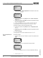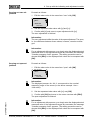
1
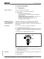
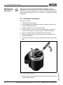
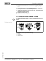
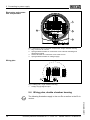
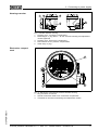
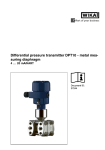
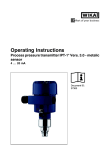
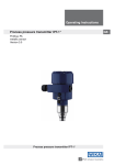
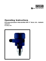
Operating Instructions
Process pressure transmitter IPT-1* Vers. 3.0 - metalic
sensor
Profibus PA
Contents
Contents
1
About this document
1.1
1.2
1.3
2
.
.
.
.
.
.
.
.
.
..
..
..
..
..
..
..
..
..
5
5
5
5
6
6
6
6
6
.
.
.
.
.
.
.
.
.
.
.
.
.
.
.
.
.
.
.
.
.
.
.
.
..
..
..
..
7
8
8
9
General instructions . . . . . . . . . . . . . . . . . . . . . . . . .
Mounting instructions . . . . . . . . . . . . . . . . . . . . . . . .
Mounting steps. . . . . . . . . . . . . . . . . . . . . . . . . . . . .
10
12
12
Configuration . . . . . . . . . . . . . . .
Principle of operation . . . . . . . . .
Operation. . . . . . . . . . . . . . . . . .
Packaging, transport and storage
.
.
.
.
.
.
.
.
.
.
.
.
.
.
.
.
.
.
.
.
.
.
.
.
.
.
.
.
.
.
.
.
.
.
.
.
.
.
.
.
.
.
.
..
..
..
..
..
13
14
15
16
18
.
.
.
.
.
.
.
.
.
.
.
.
.
.
.
.
.
.
..
..
..
..
..
..
20
20
22
23
32
34
Parameter adjustment with PDM . . . . . . . . . . . . . . . .
35
Preparing the connection . . . . . . . . .
Connection procedure. . . . . . . . . . . .
Wiring plan, single chamber housing .
Wiring plan, double chamber housing
Switch on phase. . . . . . . . . . . . . . . .
.
.
.
.
.
.
.
.
.
.
.
.
.
.
.
.
.
.
.
.
.
.
.
.
.
.
.
.
.
.
.
.
.
.
.
Short description . . . . . . . . . . . . . . . . .
Insert indicating and adjustment module.
Adjustment system . . . . . . . . . . . . . . . .
Setup procedure. . . . . . . . . . . . . . . . . .
Menu schematic . . . . . . . . . . . . . . . . . .
Saving the parameter adjustment data . .
.
.
.
.
.
.
.
.
.
.
.
.
.
.
.
.
.
.
.
.
.
.
.
.
.
.
.
.
.
.
Maintenance, cleaning . . . . . . . . . . . . . . . . . . . . . . .
Remove interferences . . . . . . . . . . . . . . . . . . . . . . . .
36
36
Process pressure transmitter IPT-1* Vers. 3.0 - metalic sensor • Profibus PA
31544-EN-081211
Maintenance and fault rectification
8.1
8.2
2
.
.
.
.
.
.
.
.
.
Setup with PDM
7.1
8
.
.
.
.
.
.
.
.
.
Set up with the indicating and adjustment module
6.1
6.2
6.3
6.4
6.5
6.6
7
.
.
.
.
.
.
.
.
.
Connecting to power supply
5.1
5.2
5.3
5.4
5.5
6
.
.
.
.
.
.
.
.
.
Mounting
4.1
4.2
4.3
5
.
.
.
.
.
.
.
.
.
Authorised personnel . . . . . . . . . . . . . . . .
Appropriate use . . . . . . . . . . . . . . . . . . . .
Warning about misuse . . . . . . . . . . . . . . .
General safety instructions . . . . . . . . . . . .
Safety approval markings and safety tips . .
CE conformity . . . . . . . . . . . . . . . . . . . . .
Fulfillment of NAMUR recommendations . .
Safety instructions for Ex areas . . . . . . . . .
Safety instructions for oxygen applications .
Product description
3.1
3.2
3.3
3.4
4
4
4
4
For your safety
2.1
2.2
2.3
2.4
2.5
2.6
2.7
2.8
2.9
3
Function. . . . . . . . . . . . . . . . . . . . . . . . . . . . . . . . . .
Target group . . . . . . . . . . . . . . . . . . . . . . . . . . . . . .
Symbolism used. . . . . . . . . . . . . . . . . . . . . . . . . . . .
Contents
8.3
9
Instrument repair . . . . . . . . . . . . . . . . . . . . . . . . . . .
38
Dismounting
9.1
9.2
Dismounting steps . . . . . . . . . . . . . . . . . . . . . . . . . .
Disposal . . . . . . . . . . . . . . . . . . . . . . . . . . . . . . . . .
39
39
10 Supplement
10.1 Technical data . . . . . . . . . . . . . . . . . . . . . . . . . . . . .
10.2 Information on Profibus PA . . . . . . . . . . . . . . . . . . . .
10.3 Dimensions . . . . . . . . . . . . . . . . . . . . . . . . . . . . . . .
40
46
51
Supplementary documentation
Information:
Supplementary documents appropriate to the ordered version come
with the delivery. You can find them listed in chapter "Product
description".
31544-EN-081211
Instructions manuals for accessories and replacement parts
Tip:
To ensure reliable setup and operation of your IPT-1* Vers. 3.0, we
offer accessories and replacement parts. The associated documents
are:
l
Operating instructions manual "External indicating and adjustment
unit"
Process pressure transmitter IPT-1* Vers. 3.0 - metalic sensor • Profibus PA
3
1 About this document
1 About this document
1.1 Function
This operating instructions manual provides all the information you
need for mounting, connection and setup as well as important
instructions for maintenance and fault rectification. Please read this
information before putting the instrument into operation and keep this
manual accessible in the immediate vicinity of the device.
1.2 Target group
This operating instructions manual is directed to trained qualified
personnel. The contents of this manual should be made available to
these personnel and put into practice by them.
1.3 Symbolism used
Information, tip, note
This symbol indicates helpful additional information.
Caution: If this warning is ignored, faults or malfunctions can
result.
Warning: If this warning is ignored, injury to persons and/or serious
damage to the instrument can result.
Danger: If this warning is ignored, serious injury to persons and/or
destruction of the instrument can result.
Ex applications
This symbol indicates special instructions for Ex applications.
l
à
1
List
The dot set in front indicates a list with no implied sequence.
Action
This arrow indicates a single action.
Sequence
Numbers set in front indicate successive steps in a procedure.
31544-EN-081211
4
Process pressure transmitter IPT-1* Vers. 3.0 - metalic sensor • Profibus PA
2 For your safety
2 For your safety
2.1 Authorised personnel
Mount and set up the pressure transmitter only if you know the
applicable national regulations and have the appropriate qualification.
You must be aquainted with the regulations and instructions for
hazardous areas, measurement and control technology as well as
electrical circuits because the pressure transmitter is "electrical
equipment" according to EN 50178. Depending on the application
conditions, it is necessary that you have appropriate knowledge, e.g.
concerning corrosive products or high pressure.
2.2 Appropriate use
IPT-1* Vers. 3.0 is a pressure transmitter for measurement of gauge
pressure, absolute pressure and vacuum.
You can find detailed information on the application range in chapter
"Product description".
Operational reliability is ensured only if the instrument is properly used
according to the specifications in the operating instructions manual as
well as possible supplementary instructions.
For safety and warranty reasons, any invasive work on the device
beyond that described in the operating instructions manual may be
carried out only by personnel authorised by the manufacturer. Arbitrary
conversions or modifications are explicitly forbidden.
2.3 Warning about misuse
Inappropriate or incorrect use of the instrument can give rise to
application-specific hazards, e.g. vessel overfill or damage to system
components through incorrect mounting or adjustment.
2.4 General safety instructions
This is a high-tech instrument requiring the strict observance of
standard regulations and guidelines. The user must take note of the
safety instructions in this operating instructions manual, the countryspecific installation standards as well as all prevailing safety
regulations and accident prevention rules.
31544-EN-081211
The instrument must only be operated in a technically flawless and
reliable condition. The operator is responsible for trouble-free
operation of the instrument.
During the entire duration of use, the user is obliged to determine the
compliance of the required occupational safety measures with the
current valid rules and regulations and also take note of new
regulations.
Process pressure transmitter IPT-1* Vers. 3.0 - metalic sensor • Profibus PA
5
2 For your safety
2.5 Safety approval markings and safety tips
The safety approval markings and safety tips on the device must be
observed.
2.6 CE conformity
This device fulfills the legal requirements of the applicable EC
guidelines. By attaching the CE mark, VEGA provides a confirmation
of successful testing.
2.7 Fulfillment of NAMUR recommendations
With respect to interference resistance and emitted interference, the
NAMUR recommendation NE 21 is fulfilled.
With respect to compatibility, the NAMUR recommendation NE 53 is
fulfilled. This applies also to the corresponding indicating and
adjustment components. WIKA instruments are generally upward and
downward compatible.
l
l
l
Sensor software for DTM IPT-1* Vers. 3.0 HART, PA or FF
DTM IPT-1* Vers. 3.0 for adjustment software PACTware
Indicating and adjustment module for sensor software
The parameter adjustment of the basic sensor functions is independent of the software version. The range of available functions depends
on the respective software version of the individual components.
The software version of IPT-1* Vers. 3.0 can be determined as follows:
l
l
l
via PACTware
on the type label of the electronics
via the indicating and adjustment module
2.8 Safety instructions for Ex areas
Please note the Ex-specific safety information for installation and
operation in Ex areas. These safety instructions are part of the
operating instructions manual and come with the Ex-approved
instruments.
2.9 Safety instructions for oxygen applications
For instruments in oxygen applications the special instructions in
chapters "Storage and transport", "Mounting" as well as "Technical
data" under "Process conditions"must be noted. Furthermore the valid
national regulations, implementation instructions and memorandums
of the BG (professional assoc.) must be noted.
31544-EN-081211
6
Process pressure transmitter IPT-1* Vers. 3.0 - metalic sensor • Profibus PA
3 Product description
3 Product description
3.1 Configuration
Scope of delivery
The scope of delivery encompasses:
l
l
IPT-1* Vers. 3.0 process pressure transmitter
Documentation
- this operating instructions manual
- Operating instructions manual "Indicating and adjustment
module" (optional)
- Supplementary instructions manual "Plug connector for continuously measuring sensors" (optional)
- Ex-specific "Safety instructions" (with Ex-versions)
- if necessary, further certificates
Supplementary label
"Oil and grease-free for
oxygen applications"
Instruments in the version "Oil and grease-free for oxygen applications" are equipped with a supplementary label. The supplementary label contains instructions on oil and grease-free parts of
the instrument.
Components
IPT-1* Vers. 3.0 consists of the following components:
l
l
l
Process fitting with measuring cell
Housing with electronics, optionally available with plug connector
Housing cover, optionally available with indicating and adjustment
module
The components are available in different versions.
1
2
31544-EN-081211
3
Fig. 1: Example of a IPT-1* Vers. 3.0 with manometer connection G½ A
according to EN 837 and Alu housing
1 Housing cover with integrated indicating and adjustment module (optional)
2 Housing with electronics
3 Process fitting with measuring cell
Type label
The type label contains the most important data for identification and
use of the instrument:
l
Article number
Process pressure transmitter IPT-1* Vers. 3.0 - metalic sensor • Profibus PA
7
3 Product description
l
l
Serial number
Technical data
3.2 Principle of operation
Application area
IPT-1* Vers. 3.0 is a pressure transmitter for measurement of
overpressure, absolute pressure or vacuum. Measured products are
gases, vapours and liquids in measuring ranges up to 4000 bar
(400 MPa); with front-flush version also viscous liquids in measuring
ranges up to 600 bar (60 MPa).
Functional principle
The process pressure acts on the sensor element via the stainless
steel diaphragm. The process pressure causes a resistance change
which is converted into a corresponding output signal and outputted as
measured value.1)
Power supply and bus
communication
Power supply via the Profibus DP/PA segment coupler. A two-wire
cable according to Profibus specification serves as carrier of both
power and digital data transmission for multiple sensors. The
instrument profile of IPT-1* Vers. 3.0 corresponds to profile specification version 3.0.
GSD/EDD
The GSD (instrument master files) and bitmap files necessary for
planning your Profibus-DP-(PA) communication network are available
from the download section on the WIKA homepage www.wika.com
under "Service". There you can also find the appropriate certificates. In
a PDM environment, an EDD (Electronic Device Description) is also
required to enable the full range of sensor functions (also available as
a download).A CD with the appropriate files can be ordered via e-mail
under [email protected] or by phone from one of the WIKA
agencies.
The backlight of the indicating and adjustment module is powered by
the sensor. Prerequisite is a certain level of operating voltage.
The data for power supply are specified in chapter "Technical data".
This function is available at a later date for instruments with StEx,
WHG or ship approval as well as country-specific approvals such as
those according to FM or CSA.
3.3 Operation
IPT-1* Vers. 3.0 can be adjusted with different adjustment media:
l
l
with indicating and adjustment module
the Simatic adjustment program PDM
1)
8
Measuring ranges up to 16 bar: piezoresistive sensor element with internal
transmission liquid, with measuring ranges up to 25 bar: Strain gauge
(DMS) sensor element on the rear of the stainless steel diaphragm (dry).
Process pressure transmitter IPT-1* Vers. 3.0 - metalic sensor • Profibus PA
31544-EN-081211
The entered parameters are generally saved in IPT-1* Vers. 3.0,
optionally also in the indicating/adjustment module.
3 Product description
3.4 Packaging, transport and storage
Packaging
Your instrument was protected by packaging during transport. Its
capacity to handle normal loads during transport is assured by a test
according to DIN EN 24180.
The packaging of standard instruments consists of environmentfriendly, recyclable cardboard. For special versions, PE foam or PE foil
is also used. Dispose of the packaging material via specialised
recycling companies.
Instruments for oxygen applications are sealed in PE foil and provided
with a label "Oxygen! Use no Oil". Remove this foil just before
mounting the instrument! See instruction under "Mounting".
Transport
Transport must be carried out under consideration of the notes on the
transport packaging. Nonobservance of these instructions can cause
damage to the device.
Transport inspection
The delivery must be checked for completeness and possible transit
damage immediately at receipt. Ascertained transit damage or
concealed defects must be appropriately dealt with.
Storage
Up to the time of installation, the packages must be left closed and
stored according to the orientation and storage markings on the
outside.
Unless otherwise indicated, the packages must be stored only under
the following conditions:
Storage and transport
temperature
l
l
l
l
l
Not in the open
Dry and dust free
Not exposed to corrosive media
Protected against solar radiation
Avoiding mechanical shock and vibration
l
Storage and transport temperature see chapter "Supplement Technical data - Ambient conditions"
Relative humidity 20 … 85 %
31544-EN-081211
l
Process pressure transmitter IPT-1* Vers. 3.0 - metalic sensor • Profibus PA
9
4 Mounting
4 Mounting
4.1 General instructions
Suitability for process
conditions
Make sure that all parts of the instrument in contact with the measured
product, especially the sensor element, process seal and process
fitting, are suitable for the existing process conditions such as process
pressure, process temperature as well as the chemical properties of
the medium.
You can find the specifications in chapter "Technical data" in the or on
the type label.
Diaphragm protection
Caution:
After removal of the diaphragm protective cover, the diaphragm must
not be pressed.
Mounting position
Select an installation position you can easily reach for mounting and
connecting as well as later retrofitting of an indicating and adjustment
module. The housing can be rotated by 330° without the use of any
tools. You can also install the indicating and adjustment module in four
different positions (each displaced by 90°).
Moisture
Use the recommended cables (see chapter "Connecting to power
supply") and tighten the cable gland.
You can give your instrument additional protection against moisture
penetration by leading the connection cable downward in front of the
cable entry. Rain and condensation water can thus drain off. This
applies mainly to outdoor mounting as well as installation in areas
where high humidity is expected (e.g. through cleaning processes) or
on cooled or heated vessels.
10
Process pressure transmitter IPT-1* Vers. 3.0 - metalic sensor • Profibus PA
31544-EN-081211
Fig. 2: Measures against moisture penetration
4 Mounting
Ventilation and pressure
compensation
The ventilation of the measuring cell is realised by a filter element in
the socket of the electronics housing. The ventilation of the electronics
housing is realised via an additional filter element around the cable
glands.2)
2
1
Fig. 3: Position of the filter elements
1 Filter element for ventilation of the measuring cell
2 Filter element for ventilation of the electronics housing
Information:
Make sure that the filter elements are always free of buildup during
operation. A pressure washer must not be used for cleaning.
Temperature limits
Higher process temperatures mean often also higher ambient
temperatures.
2
1
Fig. 4: Temperature ranges
1 Process temperature
2 Ambient temperature
31544-EN-081211
Make sure that the upper temperature limits for the environment of
electronics housing and connection cable specified in chapter
"Technical data" are not exceeded.
2)
With previous instrument versions, ventilation and pressure compensation
were carried out together via a filter element.
Process pressure transmitter IPT-1* Vers. 3.0 - metalic sensor • Profibus PA
11
4 Mounting
Oxygen applications
Danger:
Instruments in the version "Oil and grease free for oxygen" should be
unpacked just before mounting. After the protective cover of the
process fitting has been removed, the label "O₂" on the process fitting
is visible. Contamination by oil, grease and dirt should be avoided.
Danger of explosion!
4.2 Mounting instructions
Mounting position
IPT-1* Vers. 3.0 functions in any installation position. It is mounted
according to the same directives as a manometer (DIN EN 839-2).3)
Information:
We recommend using lock fittings, measuring instrument holders and
siphons from the line of WIKA accessories.
4.3 Mounting steps
Welding the socket
To mount IPT-1* Vers. 3.0, a welded socket is necessary. Use
components from the line of WIKA mounting accessories.
à Note the applicable welding standards (segment welding procedure) when welding the socket.
Sealing/Screwing in
Use the seal corresponding to the instrument:
l
Process fitting GD: Tesnit seal in front of the thread
- or Seal the thread with teflon, hemp or a similar resistant seal material:
l
Process fitting GN
à Screw IPT-1* Vers. 3.0 into the welded socket. Tighten the
hexagon on the process fitting with a suitable wrench. Wrench
size, see chapter "Dimensional drawings".
Warning:
The housing must not be used to screw the instrument in! Applying
tightening force can damage internal parts of the housing.
12
Probable position correction see chapter "Setup steps".
Process pressure transmitter IPT-1* Vers. 3.0 - metalic sensor • Profibus PA
31544-EN-081211
3)
5 Connecting to power supply
5 Connecting to power supply
5.1 Preparing the connection
Note safety instructions
Always keep in mind the following safety instructions:
l
l
Connect only in the complete absence of line voltage
If overvoltage surges are expected, overvoltage arresters should
be installed according to Profibus specifications
Take note of
safety instructions for Ex applications
In hazardous areas you should take note of the appropriate
regulations, conformity and type approval certificates of the sensors
and power supply units.
Select power supply
Power is supplied via a Profibus DP/PA segment coupler. The power
supply range can differ depending on the instrument version. The
exact range is stated in the "Technical data".
Selecting connection
cable
IPT-1* Vers. 3.0 is connected with screened cable according to the
Profibus specification. Power supply and digital bus signal are carried
over the same two-wire connection cable.
Use cable with round cross-section. A cable outer diameter of 5 … 9 mm
(0.2 … 0.35 in) ensures the seal effect of the cable gland. If you are
using cable with a different diameter or cross-section, exchange the
seal or use a suitable cable gland.
Please make sure that your installation is carried out according to the
Profibus specification. In particular, make sure that the termination of
the bus is done with appropriate terminating resistors.
Cable screening and
grounding
In systems with potential equalisation, connect the cable screen
directly to ground potential at the power supply unit, in the connection
box and at the sensor. The screen in the sensor must be connected
directly to the internal ground terminal. The ground terminal outside on
the housing must be connected to the potential equalisation (low
impedance).
31544-EN-081211
In systems without potential equalisation, connect the cable screen
directly to ground potential at the power supply unit and at the sensor.
In the connection box or T-distributor, the screen of the short stub to
the sensor must not be connected to ground potential or to another
cable screen. The cable screens to the power supply unit and to the
next distributor must be connected to each other and also connected
to ground potential via a ceramic capacitor (e.g. 1 nF, 1500 V). The low
frequency potential equalisation currents are thus suppressed, but the
protective effect against high frequency interference signals remains.
The total capacitance of the cable and of all capacitors must not exceed
10 nF in Ex applications.
Process pressure transmitter IPT-1* Vers. 3.0 - metalic sensor • Profibus PA
13
5 Connecting to power supply
Select connection cable for Ex
applications
Take note of the corresponding installation regulations for Ex
applications. In particular, make sure that no potential equalisation
currents flow over the cable screen. In case of grounding on both sides
this can be achieved by the use of a capacitor or a separate potential
equalisation.
5.2 Connection procedure
Proceed as follows:
1
Unscrew the housing cover
2
If an indicating and adjustment module is installed, remove it by
turning it slightly to the left.
3
Loosen compression nut of the cable entry
4
Remove approx. 10 cm (4 in) of the cable mantle, strip approx.
1 cm (0.4 in) insulation from the ends of the individual wires
5
Insert the cable through the cable gland into the sensor
6
Lift the opening levers of the terminals with a screwdriver (see
following illustration)
7
Insert the wire ends into the open terminals according to the wiring
plan
8
14
Press down the opening levers of the terminals, you will hear the
terminal spring closing
Process pressure transmitter IPT-1* Vers. 3.0 - metalic sensor • Profibus PA
31544-EN-081211
Fig. 5: Connection steps 6 and 7
5 Connecting to power supply
9
Check the hold of the wires in the terminals by lightly pulling on
them
10 Connect the screen to the internal ground terminal, connect the
outer ground terminal with potential equalisation
11 Tighten the compression nut of the cable entry. The seal ring must
completely encircle the cable
12 Screw the housing cover on
The electrical connection is finished.
5.3 Wiring plan, single chamber housing
The following illustrations apply to the non-Ex as well as to the Ex-ia
version.
Housing overview
4
4
4
5
5
5
1
3
6: Material versions, single chamber housing
Plastic
Aluminium
Stainless steel
31544-EN-081211
Fig.
1
2
3
2
Process pressure transmitter IPT-1* Vers. 3.0 - metalic sensor • Profibus PA
15
5 Connecting to power supply
Electronics and connection compartment
Display
I²C
1
4
2
5 6 7 8
1
2
3
Fig. 7: Electronics and connection compartment, single chamber housing
1 Plug connector for service
2 Spring-loaded terminals for connection of the external indicating and
adjustment module
3 Ground terminal for connection of the cable screen
4 Spring-loaded terminals for voltage supply
Wiring plan
Display
I2C
1
2
5
6
7
8
1
Fig. 8: Wiring plan, single chamber housing
1 Voltage supply/Signal output
5.4 Wiring plan, double chamber housing
The following illustrations apply to the non-Ex as well as to the Ex-ia
version.
31544-EN-081211
16
Process pressure transmitter IPT-1* Vers. 3.0 - metalic sensor • Profibus PA
5 Connecting to power supply
Housing overview
1
2
3
5
4
Fig. 9: Double chamber housing
1 Housing cover, connection compartment
2 Blind stopper or plug M12 x 1 for the external indicating and adjustment
module (optional)
3 Housing cover, electronics compartment
4 Filter element for air pressure compensation
5 Cable entry or plug
Electronics compartment
1
Display
I²C
1
2
5 6 7 8
3
10: Electronics compartment, double chamber housing
Plug connector for service
Internal connection cable to the connection compartment
Terminals for the external indicating and adjustment module
31544-EN-081211
Fig.
1
2
3
2
Process pressure transmitter IPT-1* Vers. 3.0 - metalic sensor • Profibus PA
17
5 Connecting to power supply
Display
Connection compartment
1
3
1
I²C
2
2
Fig.
1
2
3
11: Connection compartment, double chamber housing
Plug connector for service
Ground terminal for connection of the cable screen
Spring-loaded terminals for voltage supply
Wiring plan
I2C
1
2
1
Fig. 12: Wiring plan, double chamber housing
1 Voltage supply/Signal output
5.5 Switch on phase
Switch on phase
After IPT-1* Vers. 3.0 is connected to voltage supply or after voltage
recurrence, the instrument carries out a self-check for approx. 30
seconds. The following steps are carried out:
l
18
Internal check of the electronics
Indication of the instrument type, the firmware as well as the
sensor TAGs (sensor designation)
Status byte goes briefly to fault value
Process pressure transmitter IPT-1* Vers. 3.0 - metalic sensor • Profibus PA
31544-EN-081211
l
l
5 Connecting to power supply
31544-EN-081211
Then the current measured value will be displayed and the corresponding digital output signal will be outputted to the cable.4)
4)
The values correspond to the actual measured level as well as to the settings already carried out, e.g. default setting.
Process pressure transmitter IPT-1* Vers. 3.0 - metalic sensor • Profibus PA
19
6 Set up with the indicating and adjustment module
6 Set up with the indicating and adjustment
module
6.1 Short description
Function/Configuration
The indicating and adjustment module is used for measured value
display, adjustment and diagnosis. It can be mounted in the following
housing versions and instruments:
l
l
All sensors of the IPT-1* instrument family, in the single as well as
double chamber housing (optionally in the electronics or connection compartment)
External indicating and adjustment unit
Note:
You can find detailed information on adjustment in the operating
instructions manual "Indicating and adjustment module".
6.2 Insert indicating and adjustment module
Mount/Dismount indicating and adjustment
module
The indicating and adjustment module can be inserted and removed at
any time. It is not necessary to interrupt the voltage supply.
For mounting, proceed as follows:
1
Unscrew the housing cover
2
Place the indicating and adjustment module in the desired position
on the electronics (you can choose any one of four different
positions - each displaced by 90°)
3
Press the indicating and adjustment module onto the electronics
and turn it to the right until it snaps in.
4
Screw housing cover with inspection window tightly back on
Removal is carried out in reverse order.
The indicating and adjustment module is powered by the sensor, an
additional connection is not necessary.
31544-EN-081211
20
Process pressure transmitter IPT-1* Vers. 3.0 - metalic sensor • Profibus PA
6 Set up with the indicating and adjustment module
Fig. 13: Mounting the indicating and adjustment module
31544-EN-081211
Note:
If you intend to retrofit the instrument with an indicating and adjustment
module for continuous measured value indication, a higher cover with
an inspection glass is required.
Process pressure transmitter IPT-1* Vers. 3.0 - metalic sensor • Profibus PA
21
6 Set up with the indicating and adjustment module
6.3 Adjustment system
2
1
1.1
3
Key functions
Fig.
1
2
3
14: Indicating and adjustment elements
LC display
Indication of the menu item number
Adjustment keys
l
[OK] key:
- Move to the menu overview
- Confirm selected menu
- Edit parameter
- Save value
l
[->] key to select:
- menu change
- list entry
- Select editing position
l
[+] key:
Change value of the parameter
l
Adjustment system
[ESC] key:
- interrupt input
- jump to the next higher menu
The sensor is adjusted via the four keys of the indicating and
adjustment module. The LC display indicates the individual menu
items. The functions of the individual keys are shown in the above
illustration. Approx. 10 minutes after the last pressing of a key, an
automatic reset to measured value indication is triggered. Any values
not confirmed with [OK] will not be saved.
31544-EN-081211
22
Process pressure transmitter IPT-1* Vers. 3.0 - metalic sensor • Profibus PA
6 Set up with the indicating and adjustment module
6.4 Setup procedure
Address setting
Before starting the actual parameter adjustment of a Profibus PA
sensor, the address setting must first be carried out. You will find a
detailed description in the operating instructions manual of the
indicating and adjustment module or in the online help of PACTware or
DTM.
Level or process pressure measurement
IPT-1* Vers. 3.0 can be used for level as well as for process pressure
measurement. Default setting is level measurement. The mode can be
changed in the adjustment menu.
Depending on the application only the respective subchapter "Level or
process pressure measurement" is of importance. There, you find the
individual adjustment steps.
Level measurement
Parameter adjustment "Level
measurement"
Set up IPT-1* Vers. 3.0 in the following sequence:
1
Selecting adjustment unit/density unit
2
Carry out position correction
3
Carrying out min. adjustment
4
Carrying out max. adjustment
In the menu item "Adjustment unit" you select the physical unit in which
the adjustment should be carried out, e.g. mbar, bar, psi…
The position correction compensates the influence of the mounting
position or static pressure on the measurement. It does not influence
the adjustment values.
Information:
The steps 1, 3 and 4 are not necessary for instruments which are
already preset according to customer specifications!
You can find the data on the type label on the instrument or in the
menu items of the min./max. adjustment.
The indicating and adjustment module enables the adjustmetn without
filling or pressure. Thanks to this, you can carry out your settings
already in the factory without the instrument having to be installed.
The actual measured value is also displayed in the menu items for
min./max. adjustment.
31544-EN-081211
Select unit
In this menu item you select the adjustment unit as well as the unit for
the temperature indication in the display.
To select the adjustment unit (in the example switching over from bar
to mbar) you have to proceed as follows:5)
5)
Selection options: mbar, bar, psi, Pa, kPa, MPa, inHg, mmHg, inH2O,
mmH2O.
Process pressure transmitter IPT-1* Vers. 3.0 - metalic sensor • Profibus PA
23
6 Set up with the indicating and adjustment module
1
▶
2
Push the [OK] button in the measured value display, the menu
overview is displayed.
Basic adjustment
Display
Diagnostics
Service
Info
Confirm the menu "Basic adjustment" with [OK], the menu item
"Unit" will be displayed.
Unit
Unit of measurement
bar▼
Temperature unit
°C▼
3
Activate the selection with [OK] and select "Units of measurement with [->].
4
Activate the selection with [OK] and select the requested unit with
[->] (in the example mbar).
5
Confirm with [OK] and move to position correction with [->].
The adjustment unit is hence switched over from bar to mbar.
Information:
When switching over to adjustment in a height unit (in the example
from bar to m), the density also has to be entered.
Proceed as follows:
1
Push the [OK] button in the measured value display, the menu
overview is displayed.
2
Confirm the menu "Basic adjustment" with [OK], the menu item
"Units of measurement" will be displayed.
3
Activate the selection with [OK] and select the requested unit with
[->] (in the example m).
4
Confirm with [OK], the submenu "Density unit" appears.
Unit of measurement
▶
5
Density unit
kg/dm³
pcf
Select the requested unit, e.g. kg/dm³ with [->] and confirm with
[OK], the submenu "Density" appears.
Unit of measurement
24
Process pressure transmitter IPT-1* Vers. 3.0 - metalic sensor • Profibus PA
31544-EN-081211
Density
0001000
kg/dm³
6 Set up with the indicating and adjustment module
6
Enter the requested density value with [->] and [+], confirm with
[OK] and move to position correction with [->].
The adjustment unit is hence switched over from bar to m.
Proceed as follows to select the temperature unit:6)
à Activate the selection with [OK] and select "Temperature unit
with [->].
à Activate the selection with [OK] and select the requested unit with
[->] (e.g. °F).
à Confirm with [OK].
The temperature unit is hence switched over from °C to °F.
Carry out position correction
Proceed as follows:
1
Activate in the menu item "Position correction" the selection with
[OK].
Position correction
Offset
=
+0000 mbar
53 mbar
2
▶
3
Carrying out min. adjustment
P
Select with [->], e.g. to accept actual measured value.
Position correction
Accept current measured
value?
Accept
Edit
Confirm with [OK] and move to min.(zero) adjustment with [->].
Proceed as follows:
1
Edit the % value in the menu item "Min. adjustment" with [OK].
Min. adjustment
+000.0 %
=
+0000.0 mbar
0000.0 mbar
2
Set the requested percentage value with [+] and [->].
3
Edit the requested mbar value with [OK].
4
Set the requested mbar value with [+] and [->].
5
Confirm with [+] and move to max. adjustment with [->].
31544-EN-081211
The min. adjustment is finished.
6)
Selection options: °C, °F.
Process pressure transmitter IPT-1* Vers. 3.0 - metalic sensor • Profibus PA
25
6 Set up with the indicating and adjustment module
Information:
For an adjustment with filling, you simply enter the displayed actual
measured value. If the adjustment ranges are exceeded, the message
"Outside parameter limits" appears. The editing procedure can be
aborted with [ESC] or the displayed limit value can be accepted with
[OK].
Carrying out max. adjustment
Proceed as follows:
1
Edit the % value in the menu item "Max. adjustment" with [OK].
Max. adjustment
+100.0 %
=
+1000.0 mbar
0000.0 mbar
Information:
The displayed pressure for 100 % corresponds to the nominal
measuring range of the sensor (in the above example 1 bar =
1000 mbar).
2
Set the requested percentage value with [->] and [OK].
3
Edit the requested mbar value with [OK].
4
Set the requested mbar value with [+] and [->].
5
Confirm with [OK] and move to the menu overview with [ESC].
The max. adjustment is finished.
Information:
For an adjustment with filling, you simply enter the displayed actual
measured value. If the adjustment ranges are exceeded, the message
"Outside parameter limits" appears. The editing procedure can be
aborted with [ESC] or the displayed limit value can be accepted with
[OK].
Process pressure measurement
Parameter adjustment "Process pressure
measurement"
Set up IPT-1* Vers. 3.0 in the following sequence:
1
Select application "Process pressure measurement"
2
Select the unit of measurement
3
Carry out position correction
4
Carrying out zero adjustment
5
Carrying out span adjustment
The position correction compensates the influence of the mounting
position or static pressure on the measurement. It does not influence
the adjustment values.
26
Process pressure transmitter IPT-1* Vers. 3.0 - metalic sensor • Profibus PA
31544-EN-081211
In the menu item "Adjustment unit" you select the physical unit in which
the adjustment should be carried out, e.g. mbar, bar, psi…
6 Set up with the indicating and adjustment module
In the menu items "zero" and "span" you determine the span of the
sensor, the span corresponds to the end value.
Information:
The steps 1, 3 and 4 are not necessary for instruments which are
already preset according to customer specifications!
You can find the data on the type label on the instrument or in the
menu items of the zero/span adjustment.
The indicating and adjustment module enables the adjustmetn without
filling or pressure. Thanks to this, you can carry out your settings
already in the factory without the instrument having to be installed.
The actual measured value is displayed in addition to the menu items
for zero/span adjustment.
Select application
"Process pressure
measurement"
IPT-1* Vers. 3.0 is preset to application "Level measurement".
Proceed as follows when switching over to application "Process
pressure measurement":
1
Push the [OK] button in the measured value display, the menu
overview is displayed.
2
Select the menu "Service" with [->] and confirm with [OK].
▶
3
Basic adjustment
Display
Diagnostics
Service
Info
Select the menu item "Application" with [->] and edit with [OK].
Warning:
Note the warning: "Output can change".
Select unit
4
Select with [->] "OK" and confirm with [OK].
5
Select "Process pressure" from the list and confirm with [OK].
In this menu item you select the adjustment unit as well as the unit for
the temperature indication in the display.
31544-EN-081211
To select the adjustment unit (in the example switching over from bar
to mbar) you have to proceed as follows:7)
1
Push the [OK] button in the measured value display, the menu
overview is displayed.
7)
Selection options: mbar, bar, psi, Pa, kPa, MPa, inHg, mmHg, inH2O,
mmH2O.
Process pressure transmitter IPT-1* Vers. 3.0 - metalic sensor • Profibus PA
27
6 Set up with the indicating and adjustment module
▶
2
Basic adjustment
Display
Diagnostics
Service
Info
Confirm the menu "Basic adjustment" with [OK], the menu item
"Unit" will be displayed.
Unit
Unit of measurement
bar▼
Temperature unit
°C▼
3
Activate the selection with [OK] and select "Units of measurement with [->].
4
Activate the selection with [OK] and select the requested unit with
[->] (in the example mbar).
5
Confirm with [OK] and move to position correction with [->].
The adjustment unit is hence switched over from bar to mbar.
Proceed as follows to select the temperature unit:8)
à Activate the selection with [OK] and select "Temperature unit
with [->].
à Activate the selection with [OK] and select the requested unit with
[->] (e.g. °F).
à Confirm with [OK].
The temperature unit is hence switched over from °C to °F.
Carry out position correction
Proceed as follows:
1
Activate in the menu item "Position correction" the selection with
[OK].
Position correction
Offset
=
+0000 mbar
53 mbar
2
▶
Select with [->], e.g. to accept actual measured value.
Position correction
Accept current measured
value?
Accept
Edit
3
Confirm with [OK] and move to min.(zero) adjustment with [->].
8)
Selection options: °C, °F.
Process pressure transmitter IPT-1* Vers. 3.0 - metalic sensor • Profibus PA
31544-EN-081211
28
P
6 Set up with the indicating and adjustment module
Carrying out zero adjustment
Proceed as follows:
1
Edit the mbar value in the menu item "zero" with [OK].
Zero adjustment
000.0 %
=
+0000.0 mbar
0000.0 mbar
P
2
Set the requested mbar value with [+] and [->].
3
Confirm with [+] and move to span adjustment with [->].
The zero adjustment is finished.
Information:
The zero adjustment shifts the value of the span adjustment. The span,
i.e. the difference between these values, however, remains unchanged.
Information:
For an adjustment with pressure, you simply enter the displayed actual
measured value. If the adjustment ranges are exceeded, the message
"Outside parameter limits" appears. The editing procedure can be
aborted with [ESC] or the displayed limit value can be accepted with
[OK].
Carrying out span adjustment
Proceed as follows:
1
Edit the mbar value in the menu item "span" with [OK].
Span adjustment
100.0 %
=
+1000.0 mbar
0000.0 mbar
P
Information:
The displayed pressure for 100 % corresponds to the nominal
measuring range of the sensor (in the above example 1 bar =
1000 mbar).
2
Set the requested mbar value with [->] and [OK].
3
Confirm with [OK] and move to the menu overview with [ESC].
31544-EN-081211
The span adjustment is finished.
Information:
For an adjustment with pressure, you simply enter the displayed actual
measured value. If the adjustment ranges are exceeded, the message
"Outside parameter limits" appears. The editing procedure can be
aborted with [ESC] or the displayed limit value can be accepted with
[OK].
Process pressure transmitter IPT-1* Vers. 3.0 - metalic sensor • Profibus PA
29
6 Set up with the indicating and adjustment module
Copy sensor data
This function enables reading out parameter adjustment data as well
as writing parameter adjustment data into the sensor via the indicating
and adjustment module. A description of the function is available in the
operating instructions manual "Indicating and adjustment module".
The following data are read out or written with this function:
l
l
l
l
l
l
l
l
l
l
l
Measured value presentation
Adjustment
Damping
Linearisation curve
Sensor-TAG
Displayed value
Scaling unit (Out-Scale unit)
Positions after the decimal point (scaled)
Scaling PA/Out-Scale 4 values
Unit of measurement
Language
The following safety-relevant data are not read out or written:
l
l
l
Sensor address
PIN
Application
Copy sensor data
Copy sensor data?
Reset
Basic adjustment
If the "Reset" is carried out, the sensor resets the values of the
following menu items to the reset values (see chart):9)
Menu section
Function
Reset value
Basic settings
Unit of measurement
bar
Temperature unit
°C
Zero/Min. adjustment
Measuring range begin
Span/Max. adjustment
Measuring range end
Density
1 kg/l
Display
9)
30
kg/l
Damping
0s
Linearisation
linear
Sensor-TAG
Sensor
Displayed value
PA-Out
Additional PA value
Secondary Value 1
Out-Scale-Unit
Volume/l
Scaling
0.00 to 100.0
Sensor-specific basic adjustment.
Process pressure transmitter IPT-1* Vers. 3.0 - metalic sensor • Profibus PA
31544-EN-081211
Service
Density unit
6 Set up with the indicating and adjustment module
Menu section
Function
Reset value
Decimal point indication
8888.8
The values of the following menu items are not reset with "Reset:
Menu section
Function
Reset value
Basic settings
Position correction
no reset
Display
Lighting
no reset
Service
Language
no reset
Application
no reset
Factory setting
Like basic adjustment, furthermore special parameters are reset to
default values.10)
Pointer
The min. and max. distance values are reset to the actual value.
31544-EN-081211
Optional settings
Additional adjustment and diagnosis options such as e.g. scaling,
simulation or trend curve presentation are shown in the following menu
schematic. You will find a detailed description of these menu items in
the operating instructions manual "Indicating and adjustment module".
10)
Special parameters are parameters which are set customer-specifically on
the service level with the adjustment software PACTware.
Process pressure transmitter IPT-1* Vers. 3.0 - metalic sensor • Profibus PA
31
6 Set up with the indicating and adjustment module
6.5 Menu schematic
Information:
Depending on the version and application, the highlighted menu
windows are not always available.
Basic adjustment
▶
Basic adjustment
Display
Diagnostics
Service
Info
Sensor address
1
1.1
126
Max. adjustment
100.00 %
=
100.00 mbar
0.0 mbar
1.4
Unit
Unit of measurement
bar▼
Temperature unit
°C▼
1.1
Damping
1.5
Position correction
Offset
=
0.2 mbar
0000 mbar
1.2
Linearisation curve
1.6
P
linear ▼
0s
Min. adjustment
000.0 %
=
0.0 mbar
0.0 mbar
1.3
Sensor-TAG
1.7
Sensor
Display
▶
Basic adjustment
Display
Diagnostics
Service
Info
Displayed value
2
2.1
2.4
Lighting
Switched off ▼
PA-Out
Diagnostics
▶
Basic adjustment
Display
Diagnostics
Service
Info
32
3.1
Sensor status
OK
3.2
Trend curve
3.3.1
Start trend curve?
Process pressure transmitter IPT-1* Vers. 3.0 - metalic sensor • Profibus PA
31544-EN-081211
Pointer
p-min.: -5.8 mbar
p-max.: 167.5 mbar
T-min.: -12.5 °C
T-max.: +85.5 °C
3
6 Set up with the indicating and adjustment module
Service
▶
Basic adjustment
Display
Diagnostics
Service
Info
Additional PA value
4
4.1
Secondary Value 1
Reset
4.2
Volume
l
4.3
Select reset ▼
Application
Out-Scale-Unit
Language
4.6
Deutsch
PA-Out-Scale
100.00 lin %
= 0.0 l
0.00 lin %
= 100.0 l
4.3
Copy sensor data
4.7
Simulation
4.2
Start simulation ▼
Copy sensor data?
4.8
PIN
Enable?
4.9
Level ▼
Info
▶
Basic adjustment
Display
Diagnostics
Service
Info
Sensor type
5.1
Date of manufacture
e.g. 16. May 2008
Software version
e.g. 3.50
5.2
Last change using PC
5.3
Sensor characteristics
5.4
Display now?
e.g. 16. May 2008
31544-EN-081211
Serial number
12345678
5
Process pressure transmitter IPT-1* Vers. 3.0 - metalic sensor • Profibus PA
33
6 Set up with the indicating and adjustment module
6.6 Saving the parameter adjustment data
It is recommended noting the adjusted data, e.g. in this operating
instructions manual and archive them afterwards. They are hence
available for multiple use or service purposes.
If IPT-1* Vers. 3.0 is equipped with an indicating and adjustment
module, the most important data can be read out of the sensor into
indicating and adjustment module. The procedure is described in the
operating instructions manual "Indicating and adjustment module" in
the menu item "Copy sensor data". The data remain there permanently
even if the sensor power supply fails.
If it is necessary to exchange the sensor, the indicating and adjustment
module is inserted into the replacement instrument and the data are
written into the sensor under the menu item "Copy sensor data".
31544-EN-081211
34
Process pressure transmitter IPT-1* Vers. 3.0 - metalic sensor • Profibus PA
7 Setup with PDM
7 Setup with PDM
7.1 Parameter adjustment with PDM
For WIKA sensors, instrument descriptions for the adjustment program
PDM are available as EDD. The instrument descriptions are already
implemented in the current version of PDM. For older versions of PDM,
a free-of-charge download is available via Internet.
31544-EN-081211
Go via www.wika.com to the item "Service".
Process pressure transmitter IPT-1* Vers. 3.0 - metalic sensor • Profibus PA
35
8 Maintenance and fault rectification
8 Maintenance and fault rectification
8.1 Maintenance, cleaning
When used in the correct way, no special maintenance is required in
normal operation.
In some applications, product buildup on the sensor diaphragm can
influence the measuring result. Depending on the sensor and
application, take precautions to ensure that heavy buildup, and
especially a hardening thereof, is avoided.
If necessary, the transmitter has to be cleaned. In this case, make sure
that the materials are resistant against the cleaning detergents.
8.2 Remove interferences
Reaction when malfunctions occur
The operator of the system is responsible for taken suitable measures
to remove interferences.
Causes of malfunction
A maximum of reliability is ensured. Nevertheless, faults can occur
during operation. These may be caused by the following, e.g.:
l
l
l
l
Sensor
Process
Power supply
Signal processing
Fault rectification
The first measures to be taken are to check the output signals as well
as to evaluate the error messages via the indicating and adjustment
module. The procedure is described below. Further comprehensive
diagnostics can be carried out on a PC with the software PACTware
and the suitable DTM. In many cases, the causes can be determined
in this way and faults can be rectified.
Checking Profibus PA
? When an additional instrument is connected, the segment fails.
l
Max. supply current of the segment coupler exceeded
à Measure the current consumption, reduce size of segment
? Wrong presentation of the measured value in Simatic S5
l
Simatic S5 cannot interpret the number format IEEE of the
measured value
à Insert converting component from Siemens
? In Simatic S7 the measured value is always presented as 0
l
Only four bytes are consistently loaded in the PLC
36
Process pressure transmitter IPT-1* Vers. 3.0 - metalic sensor • Profibus PA
31544-EN-081211
à Use function component SFC 14 to load 5 bytes consistently
8 Maintenance and fault rectification
? Measured value on the indicating and adjustment module does not
correspond to the value in the PLC
l
The menu item "Display - Display value" is not set to "PA-Out"
à Check values and correct, if necessary
? No connection between PLC and PA network
l
Incorrect adjustment of the bus parameter and the segment
coupler-dependent baud rate
à Check data and correct, if necessary
? Instrument does not appear during connection setup
l
Profibus DP cable pole-reversed
à Check cable and correct, if necessary
l
Incorrect termination
à Check termination at the beginning and end points of the bus
and terminate, if necessary, according to the specification
l
Instrument not connected to the segment, double assignment
of an address
à Check and correct, if necessary
In Ex applications, the regulations for the wiring of intrinsically safe
circuits must be observed.
Fault messages via the
indicating/adjustment
module
? E013
l
no measured value available11)
à Exchange instrument or return instrument for repair
? E017
l
Adjustment span too small
à repeat with modified values
? E036
l
no operable sensor software
à Carry out a software update or send the instrument for repair
? E041
l
Hardware error, electronics defective
à Exchange instrument or return instrument for repair
? E113
31544-EN-081211
l
Communication conflict
à Exchange instrument or return instrument for repair
11)
Fault message can also appear if the pressure is higher than the nominal
range.
Process pressure transmitter IPT-1* Vers. 3.0 - metalic sensor • Profibus PA
37
8 Maintenance and fault rectification
Reaction after fault rectification
Depending on the failure reason and measures taken, the steps
described in chapter "Set up" must be carried out again, if necessary.
8.3 Instrument repair
You can download a return form (24 KB) in the Internet from our
homepage www.wika.com under the item "Service".
If a repair is necessary, please proceed as follows:
l
l
l
l
l
Print and fill out one form per instrument
If necessary, state a contamination
Clean the instrument and pack it damage-proof
Attach the completed form and probably a safety data sheet to the
instrument
Please contact the agency serving you for the address of the
return shipment
By doing this you help us carry out the repair quickly and without
having to call back for needed information.
31544-EN-081211
38
Process pressure transmitter IPT-1* Vers. 3.0 - metalic sensor • Profibus PA
9 Dismounting
9 Dismounting
9.1 Dismounting steps
Warning:
Before dismounting, be aware of dangerous process conditions such
as e.g. pressure in the vessel, high temperatures, corrosive or toxic
products etc.
Take note of chapters "Mounting" and "Connecting to power supply"
and carry out the listed steps in reverse order.
9.2 Disposal
31544-EN-081211
Note:
When disposing of old instruments, take note of the valid legal and
municipal regulations. The appropriate parts must be recycled.
Process pressure transmitter IPT-1* Vers. 3.0 - metalic sensor • Profibus PA
39
10 Supplement
10 Supplement
10.1 Technical data
General data
Pressure type
Gauge pressure or gauge pressure
Measuring principle
- Measuring ranges ≤ 16 bar
-
piezoresistive with internal transmission liquid
Measuring ranges > 16 bar
Strain gauge (DMS) dry
Service interface
I²C-Bus
Materials and weights
316L corresponds to 1.4404 or 1.4435, 316Ti corresponds to 1.4571
Materials, wetted parts
- Process fitting
316Ti, Hastelloy C4
-
Diaphragm
316Ti, Hastelloy C4
-
Diaphragm from measuring range 25 bar,
with not flush version
Elgiloy 2.4711
-
Seal ring, O-ring
FKM, EPDM, NBR
Materials, non-wetted parts
- Internal transmission liquid
Synthetic oil, Halocarbon oil12)13)
-
Housing
Plastic PBT, Alu die-casting powder-coated, 316L
-
Seal between housing and housing
cover
NBR (stainless steel housing), silicone (Aluminium
housing)
-
Inspection window in housing cover for
indicating and adjustment module
Polycarbonate (UL-746-C listed)
-
Ground terminal
316Ti/316L
1.2 kg (2.646 lbs)
Weight approx.
Output variable
Output signal
digital output signal, format according to IEEE-754
Sensor address
126 (default setting)
Current value
10 mA, ±0.5 mA
Dynamic behaviour output
10 s
Run-up time approx.
13)
40
Synthetic oil for measuring ranges up to 16 bar, FDA listed for the food
processing industry. For measuring ranges up to 25 bar dry measuring cell.
Halocarbon oil: Generally in oxygen applications, not with vacuum measuring ranges, not with absolute measuring ranges < 1 barabs.
Process pressure transmitter IPT-1* Vers. 3.0 - metalic sensor • Profibus PA
31544-EN-081211
12)
10 Supplement
100 %
90 %
2
1
10 %
tT
t
tA
tS
Fig. 15: Sudden change of the process variable, dead time tT, rise time tA and step response time tS
1 Process variable
2 Output signal
Dead time
≤ 150 ms
Rise time
≤ 100 ms (10 … 90 %)
Step response time
≤ 250 ms (ti: 0 s, 10 … 90 %)
Damping (63 % of the input variable)
0 … 999 s, adjustable
Input variable
Adjustment
Adjustment range of the min./max. adjustment relating to the nominal measuring range:
- Min.
-5 … +95 %
-
Max.
-5 … +105 %
Adjustment range of the zero/span adjustment relating to the nominal measuring range:
- zero
-5 … +95 %
-
Span
Recommended max. turn down
-5 … +105 %
10 : 1 (no limitation)
Nominal measuring ranges and overload resistance
Nominal range
Overload, max. pressure Overload, min. pressure
31544-EN-081211
Gauge pressure
0 … 0.4 bar/0 … 40 kPa
2 bar/200 kPa
-1 bar/-100 kPa
0 … 1.6 bar/0 … 160 kPa
10 bar/1000 kPa
-1 bar/-100 kPa
0 … 16 bar/0 … 1.6 MPa
80 bar/8 MPa
-1 bar/-100 kPa
0 … 40 bar/0 … 4 MPa
80 bar/8 MPa
-1 bar/-100 kPa
0 … 100 bar/0 … 10 MPa
200 bar/20 MPa
-1 bar/-100 kPa
0 … 250 bar/0 … 25 MPa
500 bar/50 MPa
-1 bar/-100 kPa
0 … 600 bar/0 … 60 MPa
1200 bar/120 MPa
-1 bar/-100 kPa
Process pressure transmitter IPT-1* Vers. 3.0 - metalic sensor • Profibus PA
41
10 Supplement
Nominal range
Overload, max. pressure Overload, min. pressure
-1 … 3 bar/-100 … 300 kPa
17 bar/1700 kPa
-1 bar/-100 kPa
-1 … 5 bar/-100 … 500 kPa
35 bar/3500 kPa
-1 bar/-100 kPa
-1 … 15 bar/-100 … 1.5 MPa
80 bar/8 MPa
-1 bar/-100 kPa
Absolute pressure
0 … 0.4 bar/0 … 40 kPa
2 bar/200 kPa
0 bar abs.
0 … 1.6 bar/0 … 160 kPa
10 bar/1000 kPa
0 bar abs.
0 … 6 bar/0 … 600 kPa
35 bar/3500 kPa
0 bar abs.
0 … 16 bar/0 … 1.6 MPa
80 bar/8 MPa
0 bar abs.
Reference conditions and actuating variables (similar to DIN EN 60770-1)
Reference conditions according to DIN EN 61298-1
- Temperature
+18 … +30 °C (+64 … +86 °F)
-
Relative humidity
45 … 75 %
-
Air pressure
860 … 1060 mbar/86 … 106 kPa (12.5 … 15.4 psig)
Limit point adjustment according to IEC 61298-2
Determination of characteristics
Characteristics
linear
Reference installation position
upright, diaphragm points downward
Influence of the installation position
depending on the isolating diaphragm version
Deviation determined according to the limit point method according to IEC 6077014)
Applies to digital interfaces (HART, Profibus PA, Foundation Fieldbus) as well as to analogue
current output 4 … 20 mA. Specifications refer to the set span. Turn down (TD) is the relation
nominal measuring range/set span.
Deviation for measuring ranges 0.4 … 1000 bar
- Turn down 1 : 1 up to 5 : 1
< 0.1 %
-
Turn down > 5 : 1
< 0.02 % x TD
Deviation for measuring ranges > 1000 bar
- Turn down 1 : 1 up to 2 : 1
< 0.6 %
Deviation with absolute pressure measuring range 0.1 bar
- Turn down 1 : 1 up to 5 : 1
< 0.25 %
-
Turn down > 5 : 1
< 0.05 % x TD
Influence of the product or ambient temperature
14)
42
Incl. non-linearity, hysteresis and non-repeatability.
Process pressure transmitter IPT-1* Vers. 3.0 - metalic sensor • Profibus PA
31544-EN-081211
Applies to instruments with digital signal output (HART, Profibus PA, Foundation Fieldbus) as well
as to instruments with analogue current output 4 … 20 mA. Specifications refer to the set span.
Turn down (TD) = nominal measuring range/set span.
10 Supplement
Thermal change zero zignal, reference temperature 20 °C (68 °F):
- In the compensated temperature range
< 0.05 %/10 K x TD
0 … +100 °C (+32 … +212 °F)
-
Outside the compensated temperature
range
typ. < 0.05 %/10 K x TD
Applies also to instruments with analogue 4 … 20 mA current output and refers to the set span.
< 0.15 % at -40 … +80 °C (-40 … +176 °F)
Thermal change, current output
Long-term stability (similar to DIN 16086, DINV 19259-1 and IEC 60770-1)
Applies to digital interfaces (HART, Profibus PA, Foundation Fieldbus) as well as to analogue
current output 4 … 20 mA. Specifications refer to the set span. Turn down (TD) = nominal
measuring range/set span.
Long-term drift of the zero signal
< (0.1 % x TD)/year
Ambient conditions
Ambient, storage and transport temperature
- Standard version
-40 … +80 °C (-40 … +176 °F)
-
Standard version with indicating and
adjustment module
-15 … +70 °C (+5 … +158 °F)
-
Connection G1 A front-flush according to
EHEDG
-10 … +80 °C (+14 … +176 °F)
-
Fitting G1 A front-flush according to
EHEDG with indicating and adjustment
module
-10 … +70 °C (+14 … +158 °F)
-
Version for oxygen applications15)
-40 … +60 °C (-40 … +140 °F)
-
Version for oxygen applications with
indicating and adjustment module16)
-15 … +60 °C (+5 … +140 °F)
Process conditions
The specifications are used as an overview. For pressure stage and product temperature the
specifications on the type plate are applicable.
Product temperature standard, depending on the seal17)
- FKM (VP2/A)
-20 … +105 °C (-4 … +221 °F)
-
EPDM (A+P 75.5/KW75F)
-40 … +105 °C (-40 … +221 °F)
-
NBR (COG)
-20 … +105 °C (-4 … +221 °F)
31544-EN-081211
Product temperature front-flush threaded fitting G1 A according to EHEDG, threaded fitting
M44 x 1.25 as well as hygienic fittings, depending on seal18) 19)
15)
16)
17)
18)
19)
Up to 60 °C (140 °F).
Up to 60 °C (140 °F).
Version for oxygen applications up to 60 °C (140 °F).
Not with hygienic fitting with compression nut F40 PN40/316L
Version for oxygen applications up to 60 °C (140 °F).
Process pressure transmitter IPT-1* Vers. 3.0 - metalic sensor • Profibus PA
43
10 Supplement
-
FKM (VP2/A)
-20 … +150 °C (-4 … +302 °F)
-
EPDM (A+P 75.5/KW75F)
-30 … +150 °C (-22 … +302 °F)
-
NBR (COG)
-20 … +150 °C (-4 … +302 °F)
Vibration resistance
mechanical vibrations with 4 g and 5 … 100 Hz20)
Shock resistance
Acceleration 100 g/6 ms21)
Electromechanical data - version IP 66/IP 67
Cable entry/plug22)
- Single chamber housing
l
1 x cable gland M20 x 1.5 (cable: ø 5 … 9 mm),
1 x blind stopper M20 x 1.5
or:
l
1 x closing cap ½ NPT, 1 x blind plug ½ NPT
or:
-
Double chamber housing
l
1 x plug (depending on the version), 1 x blind
stopper M20 x 1.5
l
1 x cable entry M20 x 1.5 (cable: ø 5 … 9 mm),
1 x blind stopper M20 x 1.5; plug M12 x 1 for
the external indicating and adjustment module
(optional)
or:
l
1 x closing cap ½ NPT, 1 x blind stopper
½ NPT, plug M12 x 1 for the external indicating
and adjustment module (optional)
or:
l
Spring-loaded terminals for wire cross-section up to
1 x plug (depending on the version), 1 x blind
stopper M20 x 1.5; plug M12 x 1 for the
external indicating and adjustment module
(optional)
2.5 mm² (AWG 14)
Indicating and adjustment module
Voltage supply and data transmission
through the sensor
Indication
LC display in dot matrix
Adjustment elements
4 keys
Protection
- unassembled
IP 20
-
mounted into the sensor without cover
22)
44
Tested according to the regulations of German Lloyd, GL directive 2.
Tested according to EN 60068-2-27.
Depending on the version M12 x 1, according to DIN 43650, Harting, 7/
8" FF.
Process pressure transmitter IPT-1* Vers. 3.0 - metalic sensor • Profibus PA
31544-EN-081211
20)
21)
IP 40
10 Supplement
Materials
- Housing
-
ABS
Inspection window
Polyester foil
Power supply
Operating voltage
- Non-Ex instrument
9 … 32 V DC
-
EEx-ia instrument
9 … 24 V DC
-
EEx-d instrument
9 … 32 V DC
Operating voltage with lighted indicating and adjustment module
- Non-Ex instrument
13 … 32 V DC
-
EEx-ia instrument
13 … 24 V DC
-
EEx-d instrument
13 … 32 V DC
Power supply by
DP/PA segment coupler
max. number of sensors
32 (10 with Ex)
Electrical protective measures
Protection
- Housing, standard
IP 66/IP 6723)
Overvoltage category
III
Protection class
II
Approvals
31544-EN-081211
Depending on the version, instruments with approvals can have different technical data. For these
instruments, please note the corresponding approval documents. They are included in the scope
of delivery.
23)
Instruments with gauge pressure measuring ranges cannot detect the ambient pressure when submerged, e.g. in water. This can lead to falsification
of the measured value.
Process pressure transmitter IPT-1* Vers. 3.0 - metalic sensor • Profibus PA
45
10 Supplement
10.2 Information on Profibus PA
Instrument master file
The instrument master file (GSD) contains the characteristic data of the Profibus PA instrument.
These data are, e.g. the permissible transmission rates as well as information on diagnostics values
and the format of the measured value outputted by the PA instrument.
A bitmap file is also provided for the Profibus network planning tool. This file is installed automatically
when the GSD file is integrated. The bitmap file is used for symbolic indication of the PA instrument in
the configuration tool.
Ident number
Each Profibus instrument gets an unambiguous ident number (ID number) from the Profibus user
organisation (PNO). This ID number is also included in the name of the GSD file. For IPT-1* Vers. 3.0
the ID number is 0 x 076F(hex) and the GSD file BR__076F.GSD. As an option to this manufacturerspecific GSD file, PNO provides also a general so-called profile-specific GSD file. For IPT-1* Vers.
3.0 you have to use the general GSD file PA139701.GSD. If the general GSD file is used, the sensor
must be set to the profile-specific ident number via the DTM software. By default, the sensor operates
with the manufacturer-specific ID number.
Note:
When using the profile-specific GSD file, the PA-OUT value as well as
the temperature value are transmitted to the PLC (see block diagram
"Cyclical data traffic").
Cyclical data traffic
The master class 1 (e.g. PLC) cyclically reads out measured values from the sensor during operation.
The below block diagram below shows which data can be accessed by the PLC.
31544-EN-081211
46
Process pressure transmitter IPT-1* Vers. 3.0 - metalic sensor • Profibus PA
10 Supplement
Min-Max
adjustment
Sensor mounting
correction
bar
Sensor
characteristics
Linearization
%
Lin%
TB
Secondary
Value 2
Secondary
Value 1
Primary
Value
PROFIBUS PA-output
Source for
scaling
Scaling
Damping
Alarms
Failure
mode
Target
Mode
PA-Out
ti
FB
Select additional cyclic
value
Fig. 16: IPT-1* Vers. 3.0: Block diagram with AI (PA-OUT) value and Additional Cyclic Value
Sensor
characteristics
TB
PROFIBUS PA-output
Source for
scaling
Scaling
Damping
Alarms
Failure
mode
ti
Target
Mode
PA-Out
˚C
FB 2
31544-EN-081211
Fig. 17: IPT-1* Vers. 3.0: Block diagram with temperature value
Module of the PA sensors
For the cyclic data traffic, IPT-1* Vers. 3.0 provides the following modules:
l
AI (PA-OUT)
Process pressure transmitter IPT-1* Vers. 3.0 - metalic sensor • Profibus PA
47
10 Supplement
-
PA-OUT value of the FB1 after scaling
l
Temperature
PA-OUT value of the FB2 after scaling
l
l
-
Additional Cyclic Value
Additional cyclical value (depending on the source)
Free Place
This module must be used if a value should not be used in the data telegram of the cyclical data
traffic (e.g. replacement of the temperature and Additional Cyclic Value)
Max. three modules can be active. By means of the configuration software of the Profibus master,
you can determine the configuration of the cyclical data telegram with these modules. The procedure
depends on the respective configuration software.
Tip:
The modules are available in two versions:
l
l
Short for Profibus master supporting only one "Identifier Format"
byte, e.g. Allen Bradley
Long for Profibus master only supporting the "Identifier Format"
byte, e.g. Siemens S7-300/400
Examples of telegram configuration
In the following you will see how the modules can be combined and how the appendant data telegram
is structured.
Example 1 (standard setting) with pressure value, temperature value and additional cyclical value:
l
l
l
AI (PA-OUT)
Temperature
Additional Cyclic Value
Byte-No.
Format
Value
1
2
3
4
IEEE-754Flieskommazahl
PA-OUT
(FB1)
5
Status
Status
(FB1)
6
7
8
9
IEEE-754Flieskommazahl
Temperature
(FB2)
10
Status
Status
(FB2)
11
12 13 14
IEEE-754Flieskommazahl
Additional Cyclic
Value
15
Status
Status
Fig. 18: Telegram configuration example 1
Example 2 with pressure value and temperature value without additional cyclical value:
l
l
l
AI (PA-OUT)
Temperature
Free Place
31544-EN-081211
48
Process pressure transmitter IPT-1* Vers. 3.0 - metalic sensor • Profibus PA
10 Supplement
Byte-No.
Format
1
2
3
4
IEEE-754Flieskommazahl
PA-OUT
(FB1)
Value
5
Status
6
Status
(FB1)
7
8
9
IEEE-754Flieskommazahl
Temperature
(FB2)
10
Status
Status
(FB2)
Fig. 19: Telegram configuration example 2
Example 3 with pressure value and additional cyclical value without temperature value:
l
l
l
AI (PA-OUT)
Free Place
Additional Cyclic Value
Byte-No.
Format
1
Value
2
3
4
IEEE-754Floating point value
PA-OUT
(FB1)
5
Status
Status
(FB1)
6
7
8
9
IEEE-754Floating point value
Additional Cyclic
Value
10
Status
Status
Fig. 20: Telegram configuration example 3
Data format of the output signal
Byte4 Byte3 Byte2 Byte1 Byte0
Status
Value (IEEE-754)
Fig. 21: Data format of the output signal
The status byte corresponds to profile 3.0 "Profibus PA Profile for Process Control Devices" coded.
The status "Measured value OK" is coded as 80 (hex) (Bit7 = 1, Bit6 … 0 = 0).
The measured value is transferred as a 32 bit floating point number in the IEEE-754 format.
31544-EN-081211
Byte n+2
Byte n+3
Byte n
Byte n+1
Bit Bit Bit Bit Bit Bit Bit Bit Bit Bit Bit Bit Bit Bit Bit Bit Bit Bit Bit Bit Bit Bit Bit Bit Bit Bit Bit Bit Bit Bit Bit Bit
7 6 5 4 3 2 1 0 7 6 5 4 3 2 1 0 7 6 5 4 3 2 1 0 7 6 5 4 3 2 1 0
VZ 27 26 25 24 23 22 21 20 2-1 2-2 2-3 2-4 2-5 2-6 2-7 2-8 2-9 2-10 2-11 2-12 2-13 2-14 2-15 2-16 2-17 2-18 2-19 2-20 2-21 2-22 2-23
Sign
Significant
Significant
Exponent
Significant
Bit
Value = (-1)VZ
2 (Exponent - 127)
(1 + Significant)
Fig. 22: Data format of the measured value
Process pressure transmitter IPT-1* Vers. 3.0 - metalic sensor • Profibus PA
49
10 Supplement
Coding of the status byte associated with the PA output value
Status
code
Description according to Pro- Possible cause
fibus standard
0x00
bad - non-specific
Flash-Update active
0x04
bad - configuration error
l
l
l
l
Adjustment error
Configuration error with PV-Scale (PV-Span too small)
Unit irregularity
Error in the linearization table
0x0C
bad - sensor failure
l
l
l
l
Hardware error
Converter error
Leakage pulse error
Trigger error
0x10
bad - sensor failure
l Measured value generation error
l Temperature measurement error
0 x 1f
bad - out of service constant
"Out of Service" mode switched on
0 x 44
uncertain - last unstable value
Failsafe replacement value (Failsafe-Mode = "Last value" and
already valid measured value since switching on)
0 x 48
uncertain substitute set
l Switch on simulation
l Failsafe replacement value (Failsafe-Mode = "Fsafe value")
0 x 4c
uncertain - initial value
Failsafe replacement value (Failsafe-Mode = "Last valid value" and
no valid measured value since switching on)
0 x 51
uncertain - sensor; conversion
not accurate - low limited
Sensor value < lower limit
0 x 52
uncertain - sensor; conversion
not accurate - high limited
Sensor value > upper limit
0 x 80
good (non-cascade) - OK
OK
0 x 84
good (non-cascade) - active
block alarm
Static revision (FB, TB) changed (10 sec. active, after the parameter
of the static category was written)
0 x 89
good (non-cascade) - active ad- Lo-Alarm
visory alarm - low limited
0 x 8a
good (non-cascade) - active ad- Hi-Alarm
visory alarm - high limited
0 x 8d
good (non-cascade) - active crit- Lo-Lo-Alarm
ical alarm - low limited
0 x 8e
good (non-cascade) - active crit- Hi-Hi-Alarm
ical alarm - high limited
31544-EN-081211
50
Process pressure transmitter IPT-1* Vers. 3.0 - metalic sensor • Profibus PA
10 Supplement
10.3 Dimensions
Housing
M20x1,5/
½ NPT
2
M20x1,5/
½ NPT
116mm
(4 9/16")
ø 77 mm
(3 1/32")
M20x1,5/
½ NPT
1
M20x1,5
M20x1,5/
½ NPT
3
4
23: Housing versions (with integrated indicating and adjustment module the housing is 9 mm/0.35 in higher)
Plastic housing
Stainless steel housing
Aluminium double chamber housing
Aluminium housing
31544-EN-081211
Fig.
1
2
3
4
ø 84mm
(3 5/16")
120mm (4 23/32")
ø 77 mm
(3 1/32")
~ 116mm
(4 9/16")
ø 84mm
(3 5/16")
~ 87mm (3 27/64")
117 mm (4 39/64")
~ 69 mm
(2 23/32")
112 mm (4 13/32")
~ 69 mm
(2 23/32")
Process pressure transmitter IPT-1* Vers. 3.0 - metalic sensor • Profibus PA
51
10 Supplement
ø 6mm
(15/64")
ND
60°
ø 4,8
(3/16")
SW27
15mm
(19/32")
12mm
(15/32")
SW27
57mm
(2 1/4")
GD
¼“NPT
60°
ø 4,8
(3/16")
M 16x1,5
ML
57mm
(2 1/4")
ø 3mm
(1/8")
65mm
(2 9/16")
23mm
(29/32")
½“NPT
25mm
(63/64")
3mm
(1/8")
G½A
20mm
(25/32")
SW27
15mm
(19/32")
63mm
(2 31/64")
IPT-1* Vers. 3.0 - threaded fitting
M 20x1,5
MI
Fig. 24: IPT-1* Vers. 3.0 GD = G½ EN 837, ND = ½ NPT, ML = M16 x 1.5 inner, MI = M20 x 1.5 inner
31544-EN-081211
52
Process pressure transmitter IPT-1* Vers. 3.0 - metalic sensor • Profibus PA
10 Supplement
SW27
G½B
20,5 mm
(13/16")
ø 30 mm
(1 3/16")
86
SW60
SW41
G1B
22 mm
(55/64")
28 mm
(1 7/64")
G1½A
71 mm
(2 51/64")
85
G6
ø 18 mm
(45/64")
68 mm
(2 43/64")
20,5 mm
(13/16")
G1B
65 mm
(2 9/16")
SW41
65 mm
(2 9/16")
IPT-1* Vers. 3.0 - front-flush connection, part 1
ø 30 mm
(1 3/16")
83
31544-EN-081211
Fig. 25: IPT-1* Vers. 3.0 85 = G1 A front-flush 0 … 0.4 bar and 0 … 1.6 bar, 86 = G½ A front-flush > 1.6 bar, 84 =
G1 A front-flush up to 150 °C according to EHEDG 0 … 0.4 bar and 0 … 16 bar
Process pressure transmitter IPT-1* Vers. 3.0 - metalic sensor • Profibus PA
53
10 Supplement
81 mm
(3 3/16")
82 mm
(3 15/64")
82 mm
(3 15/64")
IPT-1* Vers. 3.0 - front-flush connection, part 2
ø50 mm
(1 31/32")
SA
RT
ø 74 mm (2 29/32")
RA
51 mm
(2 1/64")
82 mm
(3 15/64")
ø64 mm
(2 33/64")
ø 65 mm (2 9/16")
ø 84 mm (3 5/16")
ø 84 mm (3 5/16")
ø 105 mm (4 9/64")
3T
3R
Fig. 26: IPT-1* Vers. 3.0 - SA = Tri-Clamp 2", RA = bolting DN 40/PN 40 according to DIN 11851, RT = Tri-Clamp
1½", 3T = DRD, 3R = Varivent Form F
31544-EN-081211
54
Process pressure transmitter IPT-1* Vers. 3.0 - metalic sensor • Profibus PA
31544-EN-081211
10 Supplement
Process pressure transmitter IPT-1* Vers. 3.0 - metalic sensor • Profibus PA
55
Printing date::
WIKA Alexander Wiegand GmbH & Co. KG
Alexander-Wiegand-Straße 30
63911 Klingenberg/Germany
Phone +49 9372 132295
Fax +49 9372 132706
e-mail: [email protected]
www.wika.de
All statements concerning scope of delivery, application,
practical use and operating conditions of the sensors and
processing systems correspond to the information available at the time of printing.
Subject to change without prior notice
31544-EN-081211