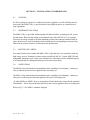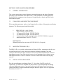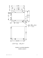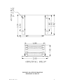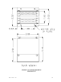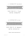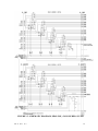
1
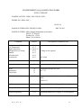
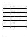
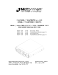
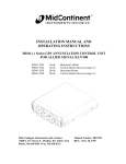
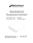
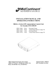
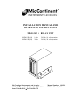
INSTALLATION MANUAL AND OPERATING INSTRUCTIONS MD41-24P( ) RELAY UNIT MD41-24P(14) MD41-24P(28) 14vdc 28vdc 24 Pole, 14 volt operation 24 Pole, 28 volt operation Mid-Continent Instruments and Avionics 9400 E. 34th Street N., Wichita, KS 67226 USA Phone 316-630-0101 Fax 316-630-0723 Manual Number 7019129 REV. B Mar. 9, 2011 REVISION DETAIL ECO Rev. 5566 Date Detail 0 03/11/99 Initial Release. B 03/09/11 Revise Sec. 1.1 & 1.2.4 to indicate relay pairing and interlock failure monitoring by means of power being applied to activating coils. Add section 2.4 Limitations to describe MOD 0 & MOD 1. Revise Fig. 3.3 to reflect MOD 1 schematic. REV. B Mar. 9 2011 2 TABLE OF CONTENTS SECTION 1 1.1 1.2 1.2.1 1.2.2 1.2.3 1.2.4 1.2.5 1.2.6 GENERAL DESCRIPTION INTRODUCTION SPECIFICATIONS, TECHNICAL PHYSICAL CHARACTERISTICS ENVIRONMENTAL CHARACTERISTICS SPECIFICATIONS, ELECTRICAL INTERFACE EQUIPMENT LIMITATIONS MAJOR COMPONENTS SECTION 2 2.1 2.2 2.3 2.4 INSTALLATION CONSIDERATIONS COOLING EQUIPMENT LOCATION ROUTING OF CABLES LIMITATIONS SECTION 3 3.1 3.2 3.3 3.4 INSTALLATION PROCEDURE GENERAL INFORMATION UNPACKING AND INSPECTING MOUNTING THE MD41-24P( ) INSTALLATION LIMITATIONS SECTION 4 4.1 4.2 POST INSTALLATION CHECKOUT PRE-INSTALLATION TEST OPERATING INSTRUCTIONS FIGURE N0. 3.1A, B, C 3.2 3.3 LIST OF ILLUSTRATIONS OUTLINE DRAWING, MOUNTING MATING CONNECTOR LAYOUT SCHEMATIC, MD41-24P( ) APPENDIX ENVIRONMENTAL QUALIFICATION FORM REV. B Mar. 9 2011 3 SECTION 1 GENERAL DESCRIPTION 1.1 INTRODUCTION The MD41-24P( ) is a remote mounted transfer relay unit specifically designed for switching a CDI or HSI Indicator between two aircraft radio navigation systems. The remote switching unit is designed for use with GPS systems where the user desires to share a common CDI or HSI between an existing NAV system and a GPS system. The 24 pole unit features eight relay pairs consisting of 3 poles per relay pair. Each relay pair can be activated individually by either voltage or ground keying or as a group by ground keying. Other design features include interlocking of transfer relays utilizing one pole per relay pair for failure monitoring. (This feature provides indication that all relays have power applied to their activating coils. It does not monitor all relay contacts or coils.) A special ILS override that will automatically force the MD41-24P to switch to NAV mode when the NAV (VOR) receiver is tuned to an ILS frequency (optional connection). Also an adjustable dimming regulator is included to provide dimmed voltage to an external annunciation (750ma max). All transfer relays have gold plated contacts and are nitrogen filled for high reliability. Two versions of the MD41-24P( ) series relay units are available: MD41-24P(14), 24 pole relay for 14 volt operation. MD41-24P(28), 24 pole relay for 28 volt operation. 1.2 SPECIFICATIONS, TECHNICAL 1.2.1 PHYSICAL CHARACTERISTICS Mounting: Width: Height: Depth: Weight: Bulkhead 2.86 Inches 1.52 Inches 2.60 Inches 0.75 lbs. 1.2.2 ENVIRONMENTAL CHARACTERISTICS Applicable Documents: Operating Temperature Range: Humidity: Altitude Range: Vibration: Operational Shock: REV. B Mar. 9 2011 RTCA DO-160C, DO-208 -55C to +70C 95% Non-Condensing 0 to 55,000 ft. Cat. M and N Rigid Mounting, 6 G Operational 15 G Crash Safety 4 1.2.3 SPECIFICATIONS, ELECTRICAL Design MD41-24P(14) (14VDC) MD41-24P(28) (28VDC) Relay contact current rating: All Solid State 2.00 Amps Max. 2.00 Amps Max. 2 Amps DC Not to exceed 30 Volts. 1.2.4 INTERFACE ILS Override JI Pin 16 Receives a logic low from the NAV (VOR) receiver when tuned to an ILS frequency. This will force the MD41-24P( ) into NAV mode regardless of the NAV/GPS selection. This connection is optional. Dimming Output J2 Pin 33 Provides an adjustable dim voltage to be used with a remote mounted annunciation unit. 750 ma max. GPS annunciation interlock. J2 Pins16 and 17 Pins 16 and 17 will short together when all transfer relays are energized. This can be be used to complete the GPS annunciation circuit to monitor that power has been applied to each relay coil. 1.2.5 EQUIPMENT LIMITATIONS NOTE: Anytime the MD41-24P( ) relay transfer system is disconnected or removed from the aircraft, the HSI/CDI will be inoperative in both NAV (VOR) and GPS. 1.2.6 MAJOR COMPONENTS The system is comprised of one major component, the MD41-24P( ). REV. B Mar. 9 2011 5 SECTION 2 INSTALLATION CONSIDERATIONS 2.1 COOLING No direct cooling is required. As with any electronic equipment, overall reliability may be increased if the MD41-24P( ) is not located near any high heat source or crowded next to other equipment. 2.2 EQUIPMENT LOCATION The MD41-24P( ) is provided with mounting rails that will allow mounting on side, rear or flat side down. Rails for end mount are an optional item. Order PN 8011911 (2 required). Locate an area large enough to facilitate mounting of unit with connector and back shell in place. Insure area is clear of mechanical obstructions and is not impeding movement of any other aircraft systems. Rails for end mount are an optional item. 2.3 ROUTING OF CABLES Care must be taken not to bundle the MD41-24P( ) logic and low level signal lines with any high energy sources. Examples of these sources include 400 HZ AC, Comm, DME, HF and transponder transmitter coax. Always use shielded wire when shown on the installation print. Avoid sharp bends in cabling and routing near aircraft control cables. 2.4 LIMITATIONS The MOD 0 relay unit interlock functionality has the capability of monitoring 1 contact per relay to indicate power has been applied to the activating coil. The MOD 1 relay unit interlock functionality has the capability of monitoring 1 contact per relay pair to indicate power has been applied to the pair of activating coils. In either MOD 0 or MOD 1 there is no guarantee of individual relay contact for the interlock functionality. This is only an indicator that relays have power applied to their activating coils. Refer to Fig. 3.3 for MOD 1 schematic diagram. REV. B Mar. 9 2011 6 SECTION 3 INSTALLATION PROCEDURES 3.1 GENERAL INFORMATION This section contains interconnect diagrams, mounting dimensions and other information pertaining to the installation of the MD41-24P( ). After installation of cabling and before installation of the equipment, insure that power is applied only to the pins specified in the interconnect diagram. 3.2 UNPACKING AND INSPECTING EQUIPMENT When unpacking equipment, make a visual inspection for evidence of damage incurred during shipment. The following parts should be included: 1. 2. 3. 4. 5. MD41-24P(14) (14volt, 24 pole) MD41-24P(28) (28volt, 24 pole) J1 Connector Kit (50 pin). MCI PN 7014509 J2 Connector Kit (50 pin). MCI PN 8012247 Vertical and horizontal mounting brackets. MCI PN 7018658 (2 required) Installation Manual. MCI PN 7019129 Optional parts, Mounting brackets for rear mount. MCI PN 8011991 (2 required) 3.3 MOUNTING THE MD41-24P( ) The MD41-24P( ) is provided with mounting rails that will allow mounting on the side, rear or with flat side down. Locate a area large enough to facilitate mounting of unit with connector and back shell in place. Insure area is clear of mechanical obstructions and is not impeding movement of any other aircraft systems. Avoid mounting close to heater vents or other high heat sources. Allow a clearance of at least 3 inches from front of unit for plug removal. 3.4 INSTALLATION LIMITATIONS Wire the aircraft harness according to figure 3-3. Use at least 24 AWG wire for all connections. You MUST use shielded wire where shown. Avoid sharp bends and routing cable near high energy sources. Care must be taken to tie the harness away from aircraft controls and cables. Normal installation techniques should be applied. Also see equipment limitations, Section 1.2.5. REV. B Mar. 9 2011 7 FIGURE 3.1A OUTLINE DRAWING VERTICAL MOUNT REV. B Mar. 9 2011 8 FIGURE 3.1B OUTLINE DRAWING HORIZONTAL MOUNT REV. B Mar. 9 2011 9 FIGURE 3.1C OUTLINE DRAWING REAR MOUNT REV. B Mar. 9 2011 10 FIGURE 3.2 MATING CONNECTOR LAYOUT REV. B Mar. 9 2011 11 FIGURE 3.3 SCHEMATIC DIAGRAM, MD41-24P( ) 24 POLE RELAY UNIT REV. B Mar. 9 2011 12 SECTION 4 POST INSTALLATION CHECKOUT 4.1 PRE INSTALLATION TESTS With the MD41-24P( ) disconnected, turn on the avionics master switch and verify that aircraft power is on J1 pin 33 .Using an ohm meter, verify J2 pin 50 is aircraft ground. 4.2 OPERATING INSTRUCTIONS Turn off the avionics master switch and connect the mating connector to the MD41-24P( ). Turn on the avionics master switch and verify the NAV/GPS annunciators transfer correctly with the appropriate switch selection. Select NAV using the NAV/GPS button. The presentation on the HSI/CDI will now be information from the NAV (VOR) receiver. Using a VOR test generator or equivalent VOR signal, verify that the presentation and operation of the HSI/CDI is correct. This will include course resolver, left-right meter, to-from meter and nav warn flag. Now select GPS on the MD41-24P( ) and tune the VOR receiver to an ILS frequency. The MD41-24P( ) will be forced to NAV mode and ILS information will be displayed on the HSI/CDI. NOTE, this feature will not work if “ILS Energize” (J1 pin 16) was not connected at the time of installation. Select GPS using the NAV/GPS button. Operate the GPS receiver through a self test cycle to verify all meters are operating correctly on the HSI/CDI. Annunciation brightness (if used) at the minimum dimming level may be adjusted by rotation of the dimmer control located on the MD41-24P( ) case. CW rotation lowers the dimming level. No periodic maintenance or calibration is necessary for continued Airworthiness of the MD41-24P( ). REV. B Mar. 9 2011 13 ENVIRONMENTAL QUALIFICATION FORM RTCA / DO160C NOMENCLATURE: MD41-24P( ) RELAY UNIT MODEL NO: MD41-24P( ) CLASS A1 MANUFACTURER TEST SPECIFICATION: MPS 7015613 MANUFACTURER: Mid-Continent Instruments and Avionics 9400 E. 34th Street N. Wichita, KS 67226 Phone (316) 630-0101 Conditions Temperature and Altitude Low Temperature High Temperature In-Flight Loss of Cooling Altitude Decompression Overpressure Section Description of Conducted Tests 4.0 Equipment tested to Categories A1 & F2 except as noted 4.5.1 4.5.2 & 4.5.3 4.5.4 Cooling air not required 4.6.1 4.6.2 4.6.3 Not Tested Temperature Variation 5.0 Equipment tested to Category B Humidity 6.0 Equipment tested to Category A Shock Operational Crash Safety 7.0 7.2 7.3 Equipment tested per DO-160C Par. 7.2.1 Vibration 8.0 Equipment tested without shockmounts to Categories M and N (Table 8-1) Explosion 9.0 Equipment identified as Category X, no test required Waterproofness 10.0 Equipment identified as Category X , no test required Fluids Susceptibility 11.0 Equipment identified as Category X, no test required REV. B Mar. 9 2011 14 Environmental Qualification (cont.) Conditions Section Description of Conducted Tests Sand and Dust 12.0 Equipment identified as Category X, no test required Fungus 13.0 Equipment identified as Category X, no test required Salt Spray 14.0 Equipment identified as Category X, no test required Magnetic Effect 15.0 Equipment tested to Class Z Power Input 16.0 Equipment tested to Category B Voltage Spike 17.0 Equipment tested to Category A Audio Frequency Susceptibility Induced Signal Susceptibility 18.0 Equipment tested to Category B 19.0 Equipment tested to Category A Radio Frequency Susceptibility Radio Frequency Emissions 20.0 Equipment tested to Category T 21.0 Equipment tested to Category Z Lightning Induced Transient Susceptibility 22.0 Equipment identified as Category X, no tests required Lightning Direct Effects 23.0 Equipment identified as Category X, no tests required Icing 24.0 Equipment identified as Category X, no test required REV. B Mar. 9 2011 15