1
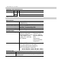
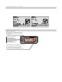
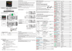
CONTROLLER
ATR111
User Manual
1 ORDERING
CODES
Ordering codes model ATR111
ATR111xx x
12…24Vac ± 10% 50/60Hz
Power supply AD
12…35Vdc
230 Vac ± 10% 50/60 Hz
B
2 TECHNICAL
DATA
Main features
Displays 3 digits (0,56 inches)
+ 1 Leds (Out1)
Operating temperature 0-40°C - humidity 35..95uR%
Sealing Front panel IP65 (with gasket) /
Box IP30 / Terminal blocks IP20
Material ABS UL94V2 self- exstinguish
Weight Approx. 100 gr.
Hardware data
Analog input AN1
Software configurable
Tolerance 25°C
Thermocouples K, J, S, R 0.5 % ± 1 digit for
PT100, NI100, PT500,
thermocouples and
PT1000, PTC 1000 ohm , RTD
NTC 10Kohm
Cold junction
0.2°c/°c of ambient
temperature
Outputs 1 Relay or SSR:
OUT1 :10A resistive on AD codes,
8A resistive with internal transformer
SSR : 8 Volt 20mA for version B
15 Volt 30mA for version AD (alim. 12Vac)
30 Volt 30mA for version AD (alim. 24Vac)
Software data
Control algorithm
Data protection
On/OFF with hysteresis or P.I.D. with Autotuning
Configuration password, quick programming by
Memory card
3 WIRING
DIAGRAM ATR111
PIXSYS
ATR111- B
PIXSYS
ATR111- AD
2 wire
I
2 wir e
4 /20 m A
+V D C PT C/N TC
6
7
8
9
10
11
1
12
1
M emo ry
2
3
M em ory
AND KEYS
Display normally shows
process value (ex. measured temperature),
but can also visualize setpoints or value of
entering data
ATR111
Visualize set, increase set
or scroll parameters
(whith fast advancement)
Visualize set, decrease set,
scroll parameters.
(whith fast advancement)
OUT 1
L1
FNC
SET
PIXSYS
Visualize setpoint (ex. programmed temperature):
press once for SET1 (Led Out1 flashes),
In configuration mode press with arrow
keys to modify value of visualized parameter.
OUT 2
4
5
6
7
8
9
10
11
Tc
+
5
S SR
Tc
+
4
+V D C PT C/N TC
230 V~
+
3
+
4 DISPLAYS
+
1
S SR
2
PT /NI 10 0 /1 K
Q1
Q1
-
V/ I
-
8A 230V
Resis ti ve
1/2H P
+
-
PT /NI 10 0 /1 K
12. ..3 5V. ..
1
4 /20 mA
+
V/ I
10A 230V
Resis ti ve
3/4H P
12/ 24V ~
I
Po we r
Po we r
12