1
GSK983M Milling CNC System
User Manual
(Volume II: Operations)
The user manual describes all matters concerning the operation of the system in detail as much as
possible. However, it is impractical to give particular descriptions of all unnecessary and/or
unavailable works on the system due to the length limit of the manual, specific operations of the
product and other causes. Therefore, the matters not specified herein may be considered
impractical or unavailable.
This user manual is the property of GSK CNC Equipment Co., Ltd. All rights reserved. It is against
the law for any organization or individual to publish or reprint this manual without the express
written permission of GSK and the latter reserves the right to ascertain their legal liability.
Foreword
Dear user,
We are really grateful for your patronage and purchase of GSK983M milling CNC system, which
is made by GSK CNC Equipment Co., Ltd.
This manual consists of two volumes. Volume I mainly describes the specifications and
programming of the system while Volume II operations, all codes, parameters, input and output
interfaces and other appendices (this is Volume II).
!
This system can only be operated by authorized and qualified personnel as improper
operations may cause accidents. Please carefully read this user manual before usage.
All specifications and designs herein are subject to change without further notice.
We are full of heartfelt gratitude to you for supporting us in the use of GSK’s products.
GSK983M Milling CNC System User Manual (Volume II: Operations)
Contents
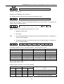
4. Operations ...................................................................................................... 3
4.1 Power on/off ............................................................................................... 3
4.1.1 Power on ................................................................................................ 3
4.1.2 Power off ................................................................................................ 3
4.2 Key switch ................................................................................................... 3
4.3 Operations relative to the operation panel .................................................. 3
4.3.1 Operation panel ....................................................................................... 3
4.3.2 Emergency stop (red) ............................................................................... 4
4.3.3 Mode selection......................................................................................... 4
4.3.4 Operations relative to manual operations..................................................... 5
4.3.5 Manual reference point return (reference position) ...................................... 11
4.3.6 Automatic operation ............................................................................... 12
4.3.7 Manual feed at any angle ........................................................................ 17
4.3.8 Manual insertion .................................................................................... 18
4.4 Display and operation on the LCD character display MDI/LCD panel ......... 19
4.4.1 Status display........................................................................................ 21
4.4.2 Key input .............................................................................................. 21
4.4.3 Display of program numbers and sequence numbers ................................... 22
4.4.4 Alarm display (function button ALARM)...................................................... 23
4.4.5 Operator information .............................................................................. 24
4.4.6 Display of actual position and reset (function key POSITION) ....................... 25
4.4.7 Indication of command value (function button COMMAND) ........................... 26
4.4.8 Setting (function button SET)................................................................... 28
4.4.9 Operating through MDI (function key COMMAND) ....................................... 32
4.4.10 Start of MDI motion .............................................................................. 33
4.4.11 Reset.................................................................................................. 33
4.4.12 Tool position offset ............................................................................... 33
4.4.13 Setting and display of workpiece origin offset (Optional) ............................ 35
4.4.14 Measurement of tool length ................................................................... 36
4.4.15 Program display (function button PROGRAM) ............................................ 36
4.4.16 Program number search (function key PROGRAM) ..................................... 38
4.4.17 Inputting a program with keys ............................................................... 39
4.4.18 Deletion of a program ........................................................................... 40
4.4.19 Deletion of all programs ........................................................................ 40
4.4.20 Sequence number search ...................................................................... 41
4.4.21 Restart of a program............................................................................. 42
4.4.22 Program number comparison stop function............................................... 46
4.4.23 Display of parameters (function button: PAR) ........................................... 46
4.4.24 Program edit........................................................................................ 47
4.4.25 Indication of running time...................................................................... 56
4.4.26 Menu switching function ........................................................................ 56
4.4.27 Operations of LCD soft function keys ....................................................... 58
1
GSK983M Milling CNC System User Manual (Volume II: Operations)
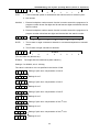
4.5 Position indication through position display unit (available upon customer’s
request) .......................................................................................................... 66
Appendix 1: Codes for programming ............................................................... 68
Appendix 2 G codes list ................................................................................... 71
Appendix 3: Ranges of command values ......................................................... 74
Appendix4 Calculating chart............................................................................ 75
Appendix 5: Parameters .................................................................................. 79
Appendix 6: Alarms list ................................................................................. 125
Appendix 7: List of the states during switching on, reset and clearance ....... 135
Appendix 8: Memory type pitch error compensation ..................................... 137
Appendix 9: Operations list ........................................................................... 144
Appendix 10: Lock of program key ................................................................ 146
Appendix 11: The interrupt function of user macro program ......................... 149
Appendix 12: Descriptions of I/O .................................................................. 161
2
GSK983M Milling CNC System User Manual (Volume II: Operations)
4. Operations
4.1 Power on/off
4.1.1 Power on
1) Make sure all parts of the machine are properly wired and secured.
2) Switch on the machine by following its manual.
3) Pictures appear on the LCD several seconds after switching on the machine.
4.1.2 Power off
1) The indicator of the running button on the operation panel of the machine goes out.
2) All moving parts of the machine stop.
3) Make sure the above operations are performed well and then press down and hold the
POWER OFF button for 1 or 2 seconds.
4) Disconnect the power supply of the machine by following its manual.
Note: Never use the keys on the MDI keypad to power on/off the machine.
4.2 Key switch
A key switch for program protection may be set with the operation panel of the machine. The key
switch offers two modes of protection:
1)
Relevant operations cannot be performed unless the key switch is actuated. However, the
concerned data is still displayed on the LCD.
2)
Operations can or cannot be performed without actuating the key switch. It is possible to
switch between the two modes by parameter.
The Section 4.4 herein will describe in detail which functions are under the protection of 1) or
2) mode.
4.3 Operations relative to the operation panel
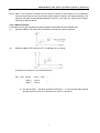
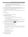
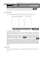
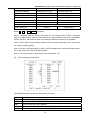
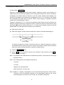
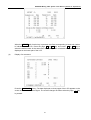
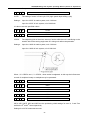
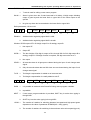
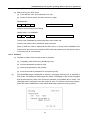
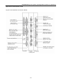
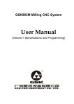
4.3.1 Operation panel
The functions of the operation panel and the layout of switches on it vary depending on different
machine types. The following is a typical operation panel. Refer to the relevant parts of the manual
supplied with the machine for details. This chapter only describes the operation panel of 3-axis control
3
GSK983M Milling CNC System User Manual (Volume II: Operations)
system (The operation panels of 4-axis and 5-axis control systems are primarily similar to that of a
3-axis control system).
80
-
90
X
Y
Z
4
+
4.3.2 Emergency stop (red)
In an emergency, press the EMERGENCY STOP button to stop the movements of all the axes
of the machine. At the same time, the button is locked in the stop position.
The release mode of the button varies with different manufacturers. In general, it is released by
pushing down and clockwise turning the button.
Note 1: The power supply of the motor is switched off when the button is pressed.
Note 2: The control unit is in reset state.
Note 3: Make sure to eliminate all troubles before releasing the button.
Note 4: Return to the reference point by through manual operations or G28 command.
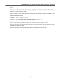
4.3.3 Mode selection
Modes
EDIT
Functions
Perform the following operations:
(1) Saving programs in storage;
(2) Modifying, inserting and deleting programs;
(3) Outputting the programs in storage and editing other programs
4
GSK983M Milling CNC System User Manual (Volume II: Operations)
AUTO
(MEMORY)
MDI
JOG
MPG
ZERO
(1) Executing the programs saved in storage;
(2) Search the sequence numbers of the programs in storage
(1) Manual data entry may be performed through MDI and the
operation panel of the machine.
(1) It is possible to perform Jog feed.
(1) It is possible to perform manual feed.
Return to the machine zero.
4.3.4 Operations relative to manual operations
Except the automatic operations that can be performed with programs, it is possible to conduct
the following manual operations with switches.
4.3.4.1 Jog feed
Jog feed enables the machine to move.
1)
Set the mode selector switch to JOG position.
2)
Select a motion axis so that the machine moves in the selected direction.
Note 1: 2 axes may be concurrently controlled by manual operation.
Note 2: After power on, the selected axis of the machine will not immediately move even the MODE
SELECTION switch is set to INCH position. Now it is necessary to reselect an axis.
3)
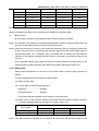
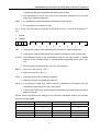
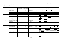
Selecting Jog feedrate
Feedrate
Position
on
rotary switch
Metric feed screw
Inch feed screw
mm/min
inch/min
inch/min
mm/min
0
0
0
0
0
1
1.0
0.04
0.02
0.508
2
1.4
0.055
0.208
0.711
3
2.0
0.079
0.04
1.02
4
2.7
0.106
0.054
1.37
5
3.7
0.146
0.074
1.88
6
5.2
0.205
0.104
2.64
7
7.2
0.283
0.144
3.66
8
10
0.394
0.2
5.08
9
14
0.551
0.28
7.11
10
20
0.787
0.40
10.2
11
27
1.06
0.54
13.7
12
37
1.46
0.74
18.8
13
52
2.05
1.04
26.4
14
72
2.83
1.44
36.6
15
100
3.94
2.00
50.8
16
140
5.51
2.80
71.1
17
200
7.87
4.00
102
5
GSK983M Milling CNC System User Manual (Volume II: Operations)
18
270
10.6
5.40
137
19
370
14.6
7.40
188
20
520
20.5
10.40
264
21
720
28.3
14.40
366
22
1000
39.4
20.00
508
23
1400
55.1
28.00
711
24
2000
78.7
40.00
1016
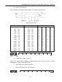
Note 1: The numerical values listed in the above table vary with different machines.
Note 2: A feedrate error (about ±3%) will exist for the feedrates in the above table.
4)
Rapid traverse
An axis rapidly traverses in the selected direction when the button is pressed.
Note 1: The feedrate, time constant and acceleration/deceleration mode for manual rapid traverse are
the same as the rapid traverse under G00 program command.
Note 2: When the machine has a memory type stroke limit selecting function, it shall be provided with
an axis with the function of returning to the reference point. When the RAPID FEED button is
pressed after power on or emergency stop, its feedrate will not change into rapid feed but
maintain at Jog feedrate provided that the function of returning to the reference point is not
executed.
This is because memory type stroke limit dose not function before the manual return to the
reference point, thereby preventing the machine from quickly reaching the end of run.
4.3.4.2 Manual feed
Make accurate adjustment for the feed of the machine with a manual pulse generator as
follows.
(1) Set the MODE SELECTION switch to MPG position.
(2) Select a motion axis.
(3) Turn the MPG of manual pulse generator.
Clockwise…………………..+ direction
Counterclockwise………
- direction
(The rotating direction depends on the settings of manufacturers)
(4) Stroke: Some of the operation panels are provided with the following selector switches:
×10 means multiplying amount of stroke by 10 while ×100 by 100.
Input system
Input in metric system
Input in inch system
The amount of stroke each step
×1
×10
×100
0.001mm
0.01mm
0.1mm
0.0001inch
0.001inch
0.01inch
Note 1: If the MPG rotates at a speed over 5 revolutions per second, the amount of the rotation of the
6
GSK983M Milling CNC System User Manual (Volume II: Operations)
MPG will differ from the stroke of the machine. Hence do not rotate the MPG too quickly.
Note 2: When ×100 override is selected and the MPG is turned at quick speed or the workbench
moves at rapid traverse rate, the machine will be subject to impact if it is stopped abruptly. The
selection automatic acceleration/deceleration function is also valid for manual feed, thereby
reducing mechanical shock.
4.3.4.3 Manual absolute
If the switch is set to ON, the stroke of manual operation will be added to the coordinate axes.
(1)
MANUAL ABSOLUTE switch ON: Coordinates change with manual operation.
(2)
MANUAL ABSOLUTE switches OFF: Coordinates do not change.
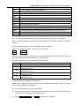
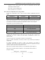
(Example) For example, in the following blocks:
…
G01
G90
X100.0
Y100.0
F010;①
X200.0
Y150.0
;②
X300.0
Y200.0
;③
…
a) The above block ① has been executed while block ② is only executed after manual
operation (stroke by 20.0 in X direction and 100.0 in Y direction).
7
GSK983M Milling CNC System User Manual (Volume II: Operations)
b) Press the FEED HOLD button in the execution of the block ②. After manual operation
(Y+75.0), press the RUNNING button so as to cancel the hold mode and continue the
execution.
c) Press the FEED HOLD button in the execution of the block ②. Reset the machine after
manual operation (Y+75.0). The block ② restarts inputting.
d)
When manual operation is followed by a single-axis command, then only the instructed
axis returns to the programmed absolute position of the axis.
N1
G01 G90
N2
X200.0;
N3
Y160.0;
X100.0
Y100.0 F5000;
8
GSK983M Milling CNC System User Manual (Volume II: Operations)
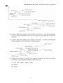
e) When manual operation is followed by an incremental command, then the position that the
axis moves to is identical with that is instructed while the MANUAL ABSOLUTE switch is
set to OFF.
Note 1: Insert manual operations when tool radius compensation C offsets. Now the actual motion path
of the tool is as follows:
(1)
MANUAL ABSOLUTE switch OFF
When tool radius compensation C is enabled:If MANUAL ABSOLUTE switch is switched off
for manual operation when tool radius compensation C is enabled, the path of the automatic
tool motion will translate in parallel by the offset of the inserted manual operation.
(2)
MANUAL ABSOLUTE switch ON
When tool radius compensation C is enabled:If MANUAL ABSOLUTE switch is switched on for
manual operation when tool radius compensation C is enabled, the path of the tool under
absolute command after restart is as follows. The tool path for the blocks after manual operation
runs parallel to the vectors of the origin of the next block.
Tool path is determined by the vectors between the next block and the block that follow. For the
angle machining with the intervention of manual operation, its tool path is identical with the above.
If a program consists of incremental commands rather than absolute commands, its tool path is
identical with that when the MANUAL ABSOLUTE switch is set to OFF.
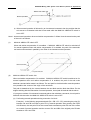
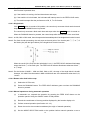
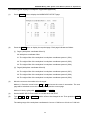
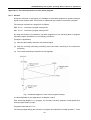
(a) Performing manual operations during execution of a block
Example 1: In the following programmed path (PA→PB→PC→PD), assuming the point PH
between PA and PB is moved to point PH′ by manual operation after pressing the FEED
HOLD button, the end point PB of the current block translates to point PB’ due to the offset
as a result of manual operation and the vectors VB1 and VB2 of the original point PB also
translate to V’B1 and V’B2.
9
GSK983M Milling CNC System User Manual (Volume II: Operations)
The vectors between the next block (tool path from PB to PC) and the one that follows
(from PC to PD) do not need compensation. The new vectors (VC1′, VC2′) with
compensation results from the relationship between the two blocks (programmed paths
from PB′ and PC to PD and from PC to PD). Since vector VB2′ coincides with VB2,
however, the section of path between PB’ and PC as a result of tool offset is not accurately
performed. But for the block after point PC, tool offset can be precisely performed.
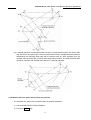
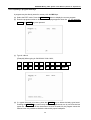
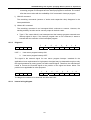
Example 2: If manual operation is inserted in angle machining in the case of tool radius
compensation, the feed path after manual operation will be determined by the same
method as Example 1. That is, the vectors VA2′, VB1′ and VB2′ in the figure below are
determined by translating the vectors VA2, VB1 and VB2 by an amount of manual stroke
and the new vectors result from VC1′ and VC2′. The block after point PC will be precisely
performed by the tool offset compensation C.
10
GSK983M Milling CNC System User Manual (Volume II: Operations)
(b) If manual operation is inserted after the execution of single block function, the vectors VB1
and VB2 for the end points of the current block will be moved in parallel and the method for
determining the following feed path will be identical with (a). MDI operation may be
inserted after the execution of a block with single block function. The feed path after MDI
operation coincides with tat after the insertion of a manual operation.
4.3.5 Manual reference point return (reference position)
The machine may return to the reference point by manual operations:
1) Set the MODE SELECTION to MANUAL.
2) Press the ZERO
key.
11
GSK983M Milling CNC System User Manual (Volume II: Operations)
3) Move all axes toward the reference point by Jog feed.
The machine rapidly traverses to the deceleration point and then to the reference point at
FL speed. Rapid traverse override is still active for quick movement.
4) The machine stops at the reference point and the indicator indicating the end of the return
to the reference point is lit.
Note 1: The indicator is lit after the return to the reference point. If the switch for returning to the
reference point is set to ON position, the machine cannot translate in Jog mode.
Note 2: The following procedures may extinguish the indicator: (1) Move the machine away from the
reference point; (2) Press the EMERGENCY STOP button.
Note 3: For the distance to the reference point, refer to the manual supplied by the manufacturer of the
machine.
4.3.6 Automatic operation
The machine may automatically operate in processes.
4.3.6.1 Starting automatic operation
Procedures for starting the program stored in memory:
(a)
Select the program number. See Section 4.4.16 “Program number search”.
(b)
Select AUTO operation mode.
(c)
Press the RUNNING button. Automatic operation starts once the RUNNING button is
pressed and at the same time the RUNNING indicator is lit.
Note 1: The programs read in are loaded when the RUNNING button is pressed in EDIT mode. The
loading mode is the same as that when the ENTER button is pressed for parameter setting.
Note 2: The RUNNING button is inactive in the following conditions:
(a) When the FEED HOLD button is pressed;
(b) When the EMERGENCY STOP button is pressed;
(c) When the RESET signal is enabled (contact the manufacturer of the machine for details);
(d) When the MODE SELECTION switch is set to a wrong position (other than AUTO or EDIT
mode);
(e) When it is search a sequence number;
(f)
When an alarm is given;
(g) When automatic operation is selected;
(h) When the NC system is not ready
4.3.6.2 Halting automatic operation
Press the FEED HOLD button
12
GSK983M Milling CNC System User Manual (Volume II: Operations)
The FEED HOLD indicator illuminates and the RUNNING indicator goes out when the FEED
HOLD button is pressed. Now,
(a) If the machine is moving, the feed slows down and stops;
(b) If the machine is in hold state, the hold state will interrupt even in the FEED HOLD mode;
(c) The machine stops after the performance of M, S, T or B function.
4.3.6.3 Single block
If the SINGLE switch is turned to ON position, the control only executes a block each time and
stops when the RUNNING button is pressed.
The control only executes a block each time and stops when the SINGLE switch is turned on.
When the RUNNING button is pressed, the control stops after the execution of the next block.
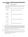
Note 1: In G28, G29 or G30 mode, the tool stops at the intermediate point if the single block function is used.
Note 2: For fixed circular processing, the tool stops at the end point of the circular path ①, ② or ⑥ of
the fixed cycle (see the figure below) if the single block function is active.
When the result of the fixed circular calculation is not 1, the FEED HOLD indicator illuminates
except the block ⑥ of the final cycle. The FEED HOLD indicator illuminates whenever block ①
or ② stops.
Note 3: For the blocks of M98P—, M99 and G65, G66 or G67, the stop of the single block is invalid.
However, it is valid if the commands in M98 or M99 block are of the addresses other than O, N,
L and P.
4.3.6.4 Restart after feed hold or stop
(1)
Select the AUTO mode;
(2)
Press the RUNNING button. The FEED HOLD indicator goes out when the RUNNING
button is pressed.
4.3.6.5 Manual operations during automatic operation
(1)
In automatic run, suspend the operation by pressing the FEED HOLD button on the
operation panel or bring the SINGLE switch to ON position.
(2)
Record the coordinates of the stop position displayed by the location display unit.
(3)
Perform manual operation (see Section 4.3.4.3).
(4)
Return the tool to the recorded coordinates (the origin of manual operation).
(5)
Set the MODE SELECTION switch to the position before manual operation so as to
13
GSK983M Milling CNC System User Manual (Volume II: Operations)
restart automatic run.
(6)
Press the RUNNING button.
4.3.6.6 MDI operation during automatic operation
(1)
Set the SINGLE switch to ON position.
(2)
Select MDI operation mode.
(3)
Perform MDI operation.
(4)
To restart automatic operation, return to the original operation mode and press the
RUNNING button on the operation panel.
Note 1: The modal data reserved in circular movement is under influence when MDI command is used.
Note 2: The modal data instructed by MDI is still valid for automatic MDI operation.
Note 3: Too radius compensation C is not performed during MDI operation.
Note 4: MDI operation is not performed in feed hold state.
4.3.6.7 Optional block skip
When some block contains “/n”(n=1 to 9), the function allows the control to skip over the block.
Switches correspond to the 19 numbers respectively.
Note: While blocks are being read in the buffer from storage, the validity of function of
skipping over optional blocks is judged. Therefore the function is invalid for the blocks read in
buffer register.
4.3.6.8 Feedrate override
For the feedrate set by F function, it is possible to set an override in the range of 10% to
200%. An override of 10% increment is recommended.
4.3.6.9 Dry run
If the switch is set to ON position in the circular operation instructed by storage or MDI, the F
function does not work and the machine strokes at the following speeds.
RAPID TRAVERSE button ON/OFF
In rapid traverse
In cutting feed
RAPID TRAVERSE button ON
Rapid traverse
Maximum Jog feedrate
RAPID TRAVERSE button OFF
Jog feedrate (see Note)
Jog feedrate
Note: The idle running of rapid traverse may be disabled or enabled by parameter setting.
4.3.6.10 Machine lock
When the MACHINE LOCK switch is set to ON, the movement command pulse is inhibited.
Therefore the position indication for circular feed start or manual operation is continuously
updated according to input commands. But the machine does not move itself. The function is
used to check procedures.
Note 1:
When G27, G28 or G30 command is set, the machine will not return to the reference point.
14
GSK983M Milling CNC System User Manual (Volume II: Operations)
Hence the indicator for returning to the reference point is not lit.
Note 2:
M, S, T and B functions are performed.
4.3.6.11 Display lock
When the DISPLAY LOCK switch is activated, the coordinates indicated by the location
display unit are locked. For instance, when the coordinate system is moved as a result of
manual operation, the use of the switch prevents manual movement from changing the
indicated values.
Note: The function is optional.
4.3.6.12 Mirror image
Once the mirror image switches of axes X and Y as well as the 4th axis are activated in
automatic operation, the axes move reversely. The reference point is returned to by manual
or automatic operation, the movement between the intermediate point and the reference
point does not inverse and position display depends on the actual movement of the tool. This
may be achieved by setting parameters with MDI unit (see Section 4.4.7).
4.3.6.13 Rapid traverse override
It is possible to set the rapid traverse override switch of optional overrides 100%, 50%, 20%
and F0 on the operation panel of the machine.
When the feed speed is 10m/min and the switch is set to 50% position, the actual feed speed
will be 5m/min.
F0 is a fixed speed (feedrate) provided by the manufacturer of the machine. The function
applies to the following conditions:
(1) The rapid traverse specified by G00;
(2) The rapid traverse in fixed cycles;
(3) The rapid traverse in G27, G28, G29 and G30 modes;
(4) Manual rapid traverse;
(5) The rapid traverse for manually returning to the reference point.
4.3.6.14 External workpiece number search function
Select a workpiece number to be processed with the switch on the operation panel of the
machine (No example of the operation panel is given in this user manual). (Machining
programs are pre-stored in the part program storage.) Press the START button. Now the
system automatically executes the program corresponding to the workpiece number. By
using the function, operator does not need to search the stored program numbers so as to
reduce idle operating time and errors.
(1) Preparation for the program: In the situations using the function, the numbers assigned
to programs shall correspond to the workpieces to be processed. That is, a number
among 01 to 31 shall be designated for each workpiece to be processed. The relevant
program number is expressed as follows:
15
GSK983M Milling CNC System User Manual (Volume II: Operations)
0(:) 0 0 □ □ (0 for EIA and : for ISO)
Workpiece number (01 to 31)
Optional workpiece number
They are stored in the part program memory. As shown in the following examples, each
program shall be started by the address 0 followed by a program number and ended by
M02, M30 or M99.
In addition, the storage of the programs irrespective of workpiece number is allowable.
0
N
0001;
0001 G00…;
The program corresponding to workpiece No. 01
……………………
……………………
N
120 M02;
0
0002;
N
0001 G00…;
……………………
……………………
N
300 M30;
0
0004;
N
001 G00………
………………………
………………………
N
080 M02;
0
6247;
N
001 G00………
………………………
………………………
N
034 M99;
The program corresponding to workpiece No. 02
The program corresponding to workpiece No. 04
Programs irrespective of workpiece number
Note 1:
Each program shall be started by the address 0 followed by a program number and ended by
M02, M30 or M99. However, M02, M30 and M99 cannot be specified in the middle of the
program. If one of them is specified in the middle section, the program that follows will
regarded as another program segment (the block following M02, M30 or M99 is immediately
numbered as a program when the program is stored in memory).
Note 2:
The allowable quantity of workpiece numbers depends on factory setting (see the manual of
the machine).
Note 3:
For the machine system provided with external workpiece number search function A, the
allowable maximum workpiece number is 31. Now the first two digits of the program number
corresponding to a workpiece number must be 00.
(1) Operating procedures
16
GSK983M Milling CNC System User Manual (Volume II: Operations)
Operating procedures vary with different manufacturers of machine. The operating
procedures described below are general. Refer to the manual supplied by manufacturer
of the machine for specific operating procedures.
Note 1:
Select the automatic mode and then set the program (01 to 31) corresponding to the
workpiece number with the rotary switch on the operation panel on the machine side. When
the START button is pressed, the program corresponding to the set workpiece number will
be searched out and machining performed with the start of the program.
Note 2:
When a workpiece number is set to 00, the corresponding program will not be searched if the
START button is pressed. The execution starts from executable section of the current
program. For the situations that starts in the midway of the program or that the executing
program is independent of workpiece number, it is necessary to set the workpiece number to
00 and press the START button after sequence number search or program number search.
Note 3:
The function does not apply to MDI operation but automatic operation.
Note 4:
If a program number corresponding to the workpiece number is not stored in the memory, an
alarm (No. 59) will be given once the START button is pressed.
Note 5:
It is not always necessary to select the relevant program even a workpiece number is
selected with the dial. Refer to the manual supplied with the machine for the procedures for
selecting a program. When workpiece number search function A is selected, program search
is performed after the NC system starts automatic operation in reset mode.
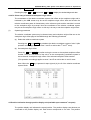
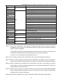
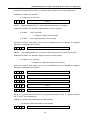
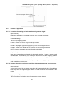
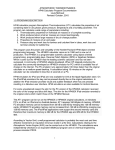
4.3.7 Manual feed at any angle
Set an angle and feedrate in the plane of X and Y and then press the RUNNING button. In
this way the machine may feed at any set angle by manual operation.
(1)
Set the MODE SELECTION switch to the mode of manual feed at any angle
(2)
Set an angle with the angle setting dial. The position of an angle is selected among 0-71
with a 2-digit BCD code. 0 ~71 correspond to 0 ~360° respectively (in 5° increment).
For angle setting, make sure to switch on angle strobe pulse. If angle strobe pulse is
17
GSK983M Milling CNC System User Manual (Volume II: Operations)
switched on, the formerly set angle will remain valid.
As shown in the above figure, the + direction of Axis X is 0° and that of Axis Y is 90°.
(3)
Select a feedrate (speed in tangential direction) with the Jog feed dial.
(4)
Press the START button in the mode of manual feed at any angle. Then the machine moves
at the selected feedrate in the set direction.
If the MAUAL RAPID TRAVERSE button is pressed, the machine will feed at the maximum
Jog feedrate. The machine feeds when the MAUAL RAPID TRAVERSE button is switched
off and stops feed when it is switched off.
Note 1:
If axes X and Y are interlocked, both axes will slow down and stop. They will restart once the
interlocking is disabled.
Note 2:
In automatic operation, it is possible to insert manual feed at any angle when the machine is
stop in feed hold mode.
Note 3:
For the situation with external deceleration selection, manual feed at any angle is also active.
Now the tangential feed is equal to the external decelerating rate.
Note 4:
The automatic acceleration and deceleration for cutting feed also apply to the manual feed at
any angle.
Note 5:
Manual feedrate at any angle does not change with Jog feedrate even during the switching
between metric and inch systems.
4.3.8 Manual insertion
For the specific axis (fixed by parameter) in automatic operation, the movements operated with
MPG may be performed in addition to the self-motion of the axis.
4.3.8.1 Inserting operations by MPG(manual pulse generator/MPG)
Manual insertion is possible by turning the manual pulse generator in the following conditions.
(1)
Mode: automatic mode or MDI mode
(2)
Operating state: Manual insertion is possible during linear interpolation, arc interpolation, spiral
interpolation or sine-curve interpolation.
However, the following conditions are excluded:
(I)
When an alarm is given;
(II) When any axis does not move;
(III) When positioning is valid;
(IV) When interlocking is active;
(V) In the absence of stroke command.
(3)
Manual axis selection signal
Manual axis selection signals (HX, HY, HZ, H4 and H5) are switched on (contacts close) for
the axes to perform manual insertion.
18
GSK983M Milling CNC System User Manual (Volume II: Operations)
4.3.8.2 Manual inserting movement by MPG
(1)
Amount of stroke: The amount of stroke to be inserted by manual shall be identical with that
during manual feed. The amount of stroke depends on the scale of the manual pulse generator
and manual feed overrides (X1, X10 and X100) and is added to that of automatic operation.
(2)
Traverse speed: The axial speed for manual insertion is the result of the addition of the stroke
speed of automatic operation to that inserted by manual. Therefore, axial speed is limited to
rapid traverse speed (Parameter HR) in the event that axial speed exceeds rapid traverse
speed. Displacement mismatches the indicated value of the manual pulse generator.
(3)
The correspondence between manual-inserted stroke and all signals is as follows:
Signal
Machine
is
locked
Display
is
locked.
Mirror image of
Axis X
(4)
(5)
Stroke
Affected: The tool does not move when MACHINE LOCK is enabled.
Affected: Relative coordinates remain unchanged when display is locked.
Not affected: The machine moves forward when the MPG is turned
clockwise.
The correspondence between manual-inserted stroke and position indications is as follows:
Indication
Stroke
Absolute
Not affected: Manual-inserted pulse is not added to absolute coordinates
coordinates
Relative
Affected: Manual-inserted pulse is added to relative coordinates
coordinates
Mechanical
Affected: Manual-inserted pulse is not added to mechanical coordinates
coordinates
Indication of amount of stroke: Manual-inserted amount of stroke may be displayed in
diagnosis message (Diagnosis No. 805 to 809). To display a diagnosis message, press the
function key DIAGNOSIS on the MDI panel.
Diagnosis data numbering
805
Manual-inserted amount of stroke of Axis X
806
Manual-inserted amount of stroke of Axis Y
807
Manual-inserted amount of stroke of Axis Z
808
Manual-inserted amount of stroke of the 4th axis
809
Manual-inserted amount of stroke of the 5th axis
Unit: 0.001mm (input in metric system)
0.0001 inch (input in inch system)
Note: Only the removable amounts of stroke are cleared.
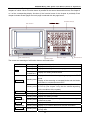
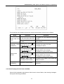
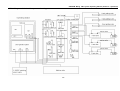
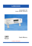
4.4 Display and operation on the LCD character display MDI/LCD panel
The MDI/LCD panel is usually mounted on the upper front side of the control cabinet. It
consists of an LCD and buttons as follows.
19
GSK983M Milling CNC System User Manual (Volume II: Operations)
Function buttons: The large number of items displayed with the function buttons is just like the
chapters of a book. When a function button is pressed for the second time and third time, the chapter 2
or 3 of the corresponding display functions (if the function button for the chapter is provided). Each
chapter includes several pages and each page is selected with the page button.
Numerical keys
LCD screen
Soft function key
Cursor keys
Function keys
End of block
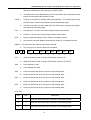
The names and meanings of all function buttons are listed below.
POSITION
SET
PROGRAM
(Called PRG)
PARAMETER
(Called PAR)
OFFSET
(Called OFT)
ALARM
(Called ALM)
COMMAND
(Called COM)
Pressing once
Display of actual position and reset
Pressing once
Display and setting of set data
Pressing twice
Display and setting of user macro program variables
Pressing for
the third time
Display and setting manual switch
Pressing once
Display of the information regarding a program in EDIT
mode
Display of the executing or executed blocks and the blocks
that follow in a mode other than EDIT
Pressing twice
Display of the list of program numbers (See Section
4.4.24.12) (The chapter 2 may also be omitted depending
on the conditions of the system.)
Pressing once
Display and setting of parameters
Pressing twice
Display and setting of PC parameters
Pressing once
Display and setting of offset
Pressing twice
Display and setting of origin offset in a workpiece
coordinate system
Pressing once
Display of the information of an alarm
Pressing twice
Display of an external alarm and external information
Pressing once
Display of command value and the commands input
through MDI
20
GSK983M Milling CNC System User Manual (Volume II: Operations)
DIAGNOSIS
(Called DGM)
Pressing twice
Display of the information regarding program restart
Pressing once
Display of system diagnostic data
Pressing twice
Display of the information regarding tool life management
Note: Clear the displayed screen by concurrently pressing a function key and CANCEL button.
The corresponding screen is displayed when the function button is pressed again.
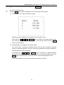
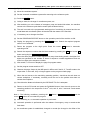
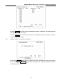
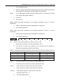
4.4.1 Status display
The status indication of the system is displayed on the lower right part of the screen:
Status indication
The displayed indications are as follows:
NOT READY indicates that the control or servo system fails to operate. LSK indicate the
LABEL SKIP mode created after power on or reset of control rather than in MDI mode. BUF
indicates that a block is read in but not executed. The block not executed still does not
disappear after reset in rather than MDI mode. ABS indicates that MDI command is absolute
and INC state will be entered into when the SHIFT (Called SHT)button is pressed. INC
indicates that MDI command is incremental ABS state will be entered into when the SHIFT
button is pressed. ALM indicates that an alarm is given. The alarm type will be displayed (the
symbol blinks) when the ALM button is pressed. EDIT indicates that the editing function is
being executed (the symbol blinks). The stopping operation of edition shall be performed when
the symbol exits. SRCH indicates that sequence search is being performed (the symbol blinks).
RESTR indicates that the period from program restart to the return to the final axis (the symbol
blinks).
4.4.2 Key input
The entries input with address keys or numerical keys are displayed at the bottom of the
screen.
21
GSK983M Milling CNC System User Manual (Volume II: Operations)
Data cannot be typed in any more when the POSITION or and ALARM button among the
function buttons is pressed to display a screen.
Press D/H to enter D and again to enter H.
Only a word consisting of one address and a figure can be typed in when Program edit is not
being performed. Pressing CANCEL once clear a word.
One or more words, a block or any character string of up to 32 characters can be entered with
the keys during Program edit.
The last entered character is cleared by pressing the CANCEL key. If the CANCEL key is
pressed continuously, the typed characters will be cleared in succession.
Note: In EDIT mode, Program edit is possible when the PROGRAM button is pressed.
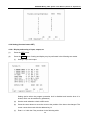
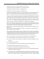
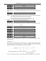
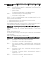
4.4.3 Display of program numbers and sequence numbers
Program numbers and sequence numbers are displayed at the top of the screen as shown in
the following picture.
22
GSK983M Milling CNC System User Manual (Volume II: Operations)
The meanings of the displayed sequence numbers and program numbers are as follows:
Mode
Mode other than
EDIT
Automatic mode
(MEMORY)
Editing mode
(EDIT)
Automatic mode
(MEMORY)
Operation
Indication
In the mode other than EDIT
To display the last displayed sequence
number
When search a sequence
number
To always display the sequence number
during search
Pressing the cursor ↑ key
when the function button is
in PROGRAM mode
To return to the start of a block
To display the block
Pressing the cursor ↓ key
when the function button is
in PROGRAM mode
To review programs in + direction from the
actual position of the storage;
To display the firstly found N value
Pressing the cursor ↑ key
when the function button is
in PROGRAM mode
To review programs in - direction from the
actual position of the storage;
To display the firstly found N value
Entering reset state by
pressing the RST button
To return to the switch of the block and
display the block
Program number search
To display
searched
the
program
numbers
4.4.4 Alarm display (function button ALARM)
When ALM is indicated at right bottom of the screen in case of alarm, clear warning messages
through the following procedures
23
GSK983M Milling CNC System User Manual (Volume II: Operations)
Press the ALARM button. When the information about operator is displayed, press the
ALARM button again to display alarm message.
Refer to Appendix 6 for the meanings of all alarm numbers
Note: As a rule, alarm message appear on the screen in the event of alarm.
4.4.5 Operator information
Once the machine sends out operator information, the information will be automatically
displayed on the screen.
When operator information appears after some other page is displayed, press the ALM button.
When alarm message appears, press it again.
24
GSK983M Milling CNC System User Manual (Volume II: Operations)
4.4.6 Display of actual position and reset (function key POSITION)
(1)
(2)
Press the POSITION button.
Press the Page button. Data is displayed in one of the following three modes.
(I)
Position display in a relative coordinate system
Relative position is displayed once operator resets a position to zero.
Reset: When the X , Y , Z or 4TH/5TH button is pressed, the pressed address codes
will continuously blink. The coordinate position of the blinking address when the SHIFT
button is pressed again.
(II) Position display in a Workpiece coordinate system
The current value of program coordinate system is set by G92, automatic coordinate
system or reset and displayed. For Axis T, the currently selected tool number is displayed.
Reset (program protection unlocking)
For resetting, the X , Y , Z or 4TH/5TH button is pressed. The pressed address
codes will continuously blink. The coordinate position of the blinking address when the
SHIFT button is pressed again. The actual position of the blinking address is reset.
Note: Reset operation can only be performed in automatic stop status.
25
GSK983M Milling CNC System User Manual (Volume II: Operations)
(III) Indication of comprehensive position
(a) The actual position is indicated in the following coordinate systems at the same time:
(b) The position in relative coordinate system (RELATIVE)
(c) The position in absolute coordinate system (ABSOLUTE)
(d) The position in machine coordinate system (MACHINE)
(e) The distance to be stroked (DISTANCE TO GO)
DISTANCE TO GO indicates the remaining distance of a block. The positions of all coordinate
systems cannot be reset when displaying the comprehensive position. The unit of machine
coordinate system is identical with that of the machine system.
4.4.7 Indication of command value (function button COMMAND)
(1)
Press the COMMAND button.
(2)
Press the PAGE button. Data is displayed in the following two modes.
26
GSK983M Milling CNC System User Manual (Volume II: Operations)
(I)
Display the formerly set modal values while executing a command value.
As shown in the above figure, the figure following character % stands for feedrate.
(II) Display the command value input by MDI or the command value to be executed next
time.
(III) Display the command value of the next block to be executed during the tool offset of tool
radius compensation C.
27
GSK983M Milling CNC System User Manual (Volume II: Operations)
4.4.8 Setting (function button SET)
4.4.8.1 Display and setting of input, output, etc
(1)
Press the SET button.
(2)
Press the PAGE button. Setting and display may be performed in the following two modes.
(I)
Setting of input and output.
Setting (active when the program protection lock is disabled and inactive when it is
locked, which can be switched by parameter)
(a)
Set the mode selection switch to MDI mode.
(b)
Press the cursor button to move the cursor to the position of the item to be changed. The
cursor cannot be moved with the address key N.
(c)
Enter 1 or 0 with the P key as shown in the following table.
28
GSK983M Milling CNC System User Manual (Volume II: Operations)
X MIRROR IMAGE)
Y MIRROR IMAGE)
0
1
MIRROR IMAGE OFF
MIRROR IMAGE ON
MIRROR IMAGE OFF
MIRROR IMAGE ON
MIRROR IMAGE OFF
MIRROR IMAGEON
TV CHECK
NO
YES
PUNCH CODE
EIA
ISO
INPUT UNIT
mm
inch
th
4 AXIS MIRROR IMAGE)
INPUT DEVICE1
DNC (can only be set to 0)
INPUT DEVICE2
Unused
Press P ,
O
or
RS232C input
1 , ENTER to proceed.
Note 1: Unselected selection function cannot be set. For example, INPUT UNIT=1 cannot be
used for a metric-system machine when metric/inch system selection function is not available.
PUNCH CODE=1 cannot be set when ISO code input selection function is not available.
Note 2: INPUT UNIT is automatically rewritten when executing G20 (input in inch system and
G21 (input in metric system).
Note 3: The ISO or EIA specified by PUNCH CODE is independent of input during data output.
ISO or EIA code can be automatically identified.
Note 4: The output device for data output is set with data No. 341.
(II)
Other settings and indications
The displayed numbers and their meanings are as follows:
Data No.
Meaning
057
Running time (Unit: hr) (TMHOR)
058
Running time (Unit: min) (TMMIN)
059
Running time (Unit: sec) (TMSEC)
067
The retraction (CYCR) in fixed cycle G73 (depth high-speed Jog touring cycle)
068
The cutting origin in fixed cycle G83 (depth Jog touring cycle)
29
GSK983M Milling CNC System User Manual (Volume II: Operations)
141
Running time (TIMDE1)
151
X value of Acme 1 of stored stroke limit 2
152
Y value of Acme 1 of stored stroke limit 2
153
Z value of Acme 1 of stored stroke limit 2
155
X value of Acme 2 of stored stroke limit 2
156
Y value of Acme 2 of stored stroke limit 2
157
Z value of Acme 2 of stored stroke limit 2
180
The sequence number whose execution has stopped
319
Settings (PROGRAM 8.MSBL)
340
Input device for selecting data storage (IDVICE)
341
Output device for selecting data for output (ODVICE)
355
Decelerating distance (automatic angle override) of the end point of block
356
Decelerating distance (automatic angle override) of the origin of block
407
Zooming override
Note 1: The data numbers other than those listed in the above table are not displayed.
Note 2: It is also possible to set the data number identical with the above table as a reference
number.
Note 3: Refer to Appendix 5 for the details about data numbering.
Note 4: The details of data No. 340 and 341 are as follows:
340
I DVICE
341
O DVICE
IDVICE is used to select an input device for storing data in memory. When the set input device
(INPUT DEVICE)2=1(Interface RS232), the setting is valid.
ODVICE is used to select an output device for data output.
Setting
0
1
2
3
4
I/O
Input: paper tape reader; output: FACIT PUNCHER
Common for input and output: ASR33/ASR43; Set
parameters to 310.
Common for input and output: reader/puncher; Set
parameters to 311.
Common for input and output: reader/puncher; Set
parameters to 312.
Common for input and output: reader/puncher; Set
parameters to 313.
baud rate and other
baud rate and other
baud rate and other
baud rate and other
It is also possible to set them by parameters.
Setting (active when the program protection lock is disabled and inactive when it is locked,
which can be switched by parameter)
(a) Set the mode selection switch to MDI mode.
(b) Press the cursor button to move the cursor to the position of the item to be changed. The
cursor cannot be moved with the address key N.
(c) Press P , numerical keys and ENTER in succession to proceed.
30
GSK983M Milling CNC System User Manual (Volume II: Operations)
4.4.8.2 Display and setting of user macro program variables
It is possible to display general variable values and the local variable values of the currently
called user macro program body on LCD.
When a variable value is <Empty>, the display will be blank. When an absolute value exceeds
99999999, it displays OVER FLOW. When an absolute value is not 0 but less than 0.0000001,
it displays UNDER FLOW.
Display
(1)
Select a set chapter 2
Press the SET button for SETTING DISPLAY and press it again.
(2)
Since the display covers 6 pages, you need to press the PAGE button to display the required
page.
Page 1——The currently called local variables #1-#20 for nesting
Page 2——The currently called local variables #21-#33 for nesting
Page 3——General variables #100-#119
Page 4——General variables #120-#139
Page 5——General variables #140-#149
Page 6——General variables #500-#509
(3)
Move the cursor to the variable number to be displayed.
Method 1: Press the cursor button and move the cursor in succession. The next page will be
switched to once the cursor goes beyond the current page.
Method 2: Set by typing with N, variable number and INPUT (active when the program
protection lock is disabled).
(a) Select MDI mode;
(b) Type with P, variable number and INPUT when the variable is displayed and the cursor is
moved to the variable number to be changed.
31
GSK983M Milling CNC System User Manual (Volume II: Operations)
4.4.9 Operating through MDI (function key COMMAND)
A program command to be executed may be input through MDI&DPL panel.
(1)
Example: X 10.5
Y200.5
(a) Set the selector switch to MDI position.
(b) Press the COMMAND button.
(c) Press the PAGE button. “Next block (command data input)” appears on the upper left of
the screen.
(d) Press the X , 1 , 0 , • and 5 keys and the INPUT button in succession. If the
numeral entered before pressing the INPUT button is incorrect, press the CANCEL button
and enter the correct numeral again. If an error is found after pressing the INPUT button,
it is necessary to enter the numeral again.
(e) Press the Y , 2 , 0 , 0 , • and 5 keys and the INPUT button. If the typed
numeral is found incorrect, proceed in the same way as inputting X.
(f)
(2)
Press the RUNNING button on the control panel of the machine.
Delete Y200.5 from X10.5 Y200.5 before pressing the RUNNING button.
32
GSK983M Milling CNC System User Manual (Volume II: Operations)
(a) Press the
Y , CANCEL and INPUT in succession.
(b) Press the RUNNING button on the control panel.
(3)
Delete modal data.
Since G code and F, D and H data cannot be deleted, it is necessary to input correct modal
data again for modification.
4.4.10 Start of MDI motion
Press the RUNNING button to execute the command input through MDI.
4.4.11 Reset
As a rule, pressing the RESET button cancels alarm state.
Once the RESET button is pressed, the NC system is set to the following states:
State before reset
In execution
command
of
a
State after reset
move
M, S, T or B
In transfer
Storage 1 of
buffer
memory,
block
The tool slows down and stops and the remaining stroke
disappears.
The transfer sequence stops. Refer to the manual supplied
with the machine for the state of the machine now.
MDI mode
The contents of the buffer memory are not eliminated.
Mode
than
mode
The contents of the buffer memory are eliminated and the
BUF label disappears.
other
MDI
In any case, pressing the RST button sets the NC system to reset state. In the modes other
than MDI, the NC system is set to the LABEL SKIP mode.
4.4.12 Tool position offset
The setting display of tool radius compensation (function button: OFFSET)
(1)
Press the OFFSET button.
(2)
Press the PAGE button and display the required page.
Position offset No. 1-12 of page 1;
Position offset No. 13-24 of page 2;
Position offset No. 25-32 or 25-36 (optional) of page 3;
Position offset No. 37-48 (optional) of page 4;
┋
┋
Position offset No. 97-99 or 97-108 (optional) of page 9;
┋
┋
33
GSK983M Milling CNC System User Manual (Volume II: Operations)
Position offset No. 193-200 (optional) of page 17;
The indication of page 1 of position offset
(3)
Move the cursor to the offset number to be changed.
Method 1: Press the cursor button and move the cursor in succession. The next page will be
switched to once the cursor goes beyond the current page.
Method 2: Set by typing with
N , variable number and INPUT.
(4)
Set the MODE SELECTION switch to a mode other than EDIT.
(5)
Type
P
and POSITION OFFSET and then press the INPUT button.
The figure below is the page after P ,
position offset number is 19.
1,
5,
•, 4
and INPUT is pressed when the
Note 1: When offset is changed in automatic operation, the new offset is not valid until its
number is specified as D or H code.
Note 2: 0-9999 INPUT is used to reset all offsets to zero.
34
GSK983M Milling CNC System User Manual (Volume II: Operations)
4.4.13 Setting and display of workpiece origin offset (Optional)
(1)
Press OFFSET twice to display the WORKPIECE OFFSET page.
(2)
Press the PAGE button to display the required page. Each page indicates as follows:
(i)
Page 1(Workpiece coordinate offset 01)
00: Workpiece coordinate offset
01: The origin offset of the workpiece in workpiece coordinate system 1 (G54)
02: The origin offset of the workpiece in workpiece coordinate system 2 (G55)
03: The origin offset of the workpiece in workpiece coordinate system 3 (G56)
(ii) Page 2(Workpiece coordinate offset 02)
04: The origin offset of the workpiece in workpiece coordinate system 4 (G57)
05: The origin offset of the workpiece in workpiece coordinate system 5 (G58)
06: The origin offset of the workpiece in workpiece coordinate system 6 (G59)
(3)
Move the cursor to the number to be changed.
Method 1: Press the cursor button ↑ or ↓ and move the cursor in succession. The next
page will be switched to once the cursor goes beyond the current page.
Method 2: Set by typing with
N , NUMBER and INPUT.
(4)
Set the MODE SELECTION switch to a mode other than EDIT.
(5)
Type X ,
button.
Y,
Z
or 4TH/5TH and the offset to be changed or set. Then press the INPUT
The setting range of the workpiece coordinates is 0 mm to ±7.999 mm or 0 inch to ±7.999 inch.
35
GSK983M Milling CNC System User Manual (Volume II: Operations)
4.4.14 Measurement of tool length
(1)
Press the OFFSET button to select the page of offset.
(2)
Select a standard tool and manually move it until it contacts the fixed point of the machine (or
fixed point of workpiece).
(3)
Press the Z and SHIFT buttons so that the relative coordinates of Axis Z is reset to zero.
(4)
Then select the tool to be measured and manually move it until it contacts the same fixed point.
Now the difference between the standard tool and that to be measured is indicated in the
display of relative position.
(5)
Just like the setting of offset, move the cursor to the offset number and press the Z and INPUT
keys but do not type in any numeral. The measured difference now is the offset to be input.
4.4.15 Program display (function button PROGRAM)
(1)
When in EDIT mode, press the PROGRAM key to display the page of the selected character
in the current selection program.
36
GSK983M Milling CNC System User Manual (Volume II: Operations)
See the program number in Section 4.16 for which program is displayed. Pressing the cursor
↓ or ↑ key displays the contents of the program in sequence. When the cursor ↓ key is
pressed, the page is displayed in forward direction. When the cursor ↑ key is pressed, it is
displayed in reverse direction.
(Note 1) Set the MODE SELECTION switch to EDIT and press the PROGRAM button to
display the contents of the program at the beginning of an executing or executed block.
However, the beginning of the program will be displayed when it is returned to (see 4.4.24.4).
(2)
In automatic operation
Press the PROGRAM button to display the current executing block.
Indications of the cursor (in automatic operation)
(a) When the cursor blinks, it indicates the block to be executed next time.
(b) When the cursor does not blink, it indicates the currently executing or executed block.
Note 1: Strictly speaking, when the buffer register becomes empty neither in automatic
operating state nor in feed hold state, the blinking of the cursor indicates the next block is
going to read in the buffer register so as to continue to execute a program.
37
GSK983M Milling CNC System User Manual (Volume II: Operations)
Note 2: When the PAGE button or cursor button is pressed in EDIT mode to move the cursor
and the program is started in memory mode, the block at the cursor in EDIT mode is read in
the buffer register.
(3)
EDIT mode and the other modes except automatic mode
When the PROGRAM button is pressed, the executing and executed blocks are displayed on
the left side of the page and the blocks to be executed next time on the right side.
Note: When an angle moves in G28, G29, a fixed cycle and tool radius compensation, the
contents on the left and right of the page are the same for the situation in which a block causes
the circular movement of several blocks.
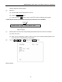
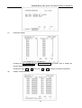
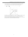
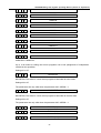
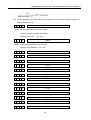
4.4.16 Program number search (function key PROGRAM)
When several programs are stored in memory, it is possible to search one of them.
0
1001
0
3054
0
1972
Search a program number
(1)
(2)
(3)
Method 1
(a)
Select a mode (EDIT or AUTO).
(b)
Press the PROGRAM key.
(c)
Enter O and the program number to be searched and then press the cursor
The switching page of the program is displayed after search.
↓
key.
Method 2
(a)
Select the AUTO mode.
(b)
Press the PROGRAM key.
(c)
Press O , CANCEL and the cursor
displayed.
↓
in sequence. The next stored program is
Method 3
(a) Select the EDIT mode
(b) Press the PROGRAM key.
(c) Press O and the cursor ↓ to display the next stored program. In addition, the stored
programs are displayed in sequence for reviewing the stored program numbers when the
cursor ↓ key is pressed continuously.
Note 1: The start position is returned to when the stored program numbers are displayed.
Note 2: The contents in the buffer register are deleted when search a program number.
38
GSK983M Milling CNC System User Manual (Volume II: Operations)
4.4.17 Inputting a program with keys
A program may be directly stored in memory with the MDI keys.
(a) Select the EDIT mode. Press the PROGRAM button to display the current program.
(b) Enter the program number to be stored. A new page appears when the O , the program
number and INSERT keys are pressed.
(c) Type in a block
[Example] When typing in G92 X500.0 Y200.0 M12,
G
9
2
X
5
0
0
.
0
2
0
0
.
0
M
1
2
EOB
Y
(d) If a typed character is incorrect, press the CANCEL key to delete the lastly typed word.
Pressing the CANCEL key continuously deletes the typed words one by one from the last
typed one. If the number of the characters of a block exceeds 32, the program cannot be
entered. Now it is possible to divide the block with proper breakpoint.
39
GSK983M Milling CNC System User Manual (Volume II: Operations)
(e) If the typed program is correct, press the INSERT key.
(f) Enter blocks in succession by this means.
(g) For correcting a typed block, proceed as indicated in the section of Program edit.
(h) For restart, continuously move the cursor to the lastly typed character. The procedure is
the same as insertion.
(i)
When all programs are input and at the end of the procedures, press the RESET key if
you want to return to the start position.
4.4.18 Deletion of a program
(Program protection lock is active; function button PROGRAM) Deleting a program stored in
memory:
(a) Select the EDIT mode.
(b) Press the PROGRAM button.
(c) Press O , the program number and DELETE. The program whose number is entered is
deleted.
4.4.19 Deletion of all programs
(Program protection lock is active; function button PROGRAM) Deleting all programs stored in
memory:
(a) Select the EDIT mode.
(b) Press the PROGRAM button.
(c) Press
O,
-,
9,
9,
9,
9
and DELETE.
40
GSK983M Milling CNC System User Manual (Volume II: Operations)
4.4.20 Sequence number search
(Function button PROGRAM)
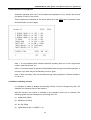
Sequence number search is usually used to search a sequence number in the midway of a
program and start or restart the program from the block whose sequence number is searched.
Its skipping over blocks exerts no influence on the NC system. Namely when skipping over
blocks, the coordinates of the blocks who are skipped over, M, S, T or G codes do not change
the coordinates and modal values of the NC. When a macro program is supplied, sequence
number will not be displayed in search.
Therefore, necessary M, S, T, G codes and coordinate system shall be set for the blocks to be
started or restarted according to sequence number. If the block needs to restart search during
machining, MDI must be used to assume M, S, T, G codes and coordinate system so that the
present state of the machine and NC system can be searched.
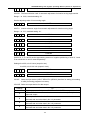
(a) Select the AUTO mode.
(b) Select the program number where the sequence number to be searched belongs to.
0………………
Selected program
Search range
To search the sequence number on the block, follow (c). When the sequence number to
be searched does not exist on the block, however, the program number with a pre-search
sequence number shall be selected for sequence number search.
(c) Press the PROGRAM button.
(d) Type in N and the sequence number to be searched. Then press the cursor
find the sequence number.
↓
to
Note 1: Coordinates and modal data do not update during search. These data are set through
MDI after search.
Note 2: The following items are checked during search.
TH check
TV check
Skipping over optional blocks
Alarm check (03, 04, 05 and 10)
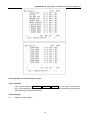
Note 3: M98P×××× (calling a subprogram) is not executed during sequence number search.
Therefore, when the sequence numbers in the subprogram called by the current
selected program for search in AUTO mode, No. 060 alarm will be given.
41
GSK983M Milling CNC System User Manual (Volume II: Operations)
In the following example, alarm will be given when N8888 is searched.
4.4.21 Restart of a program
When the machine restarts after the damage of the tool and stop of machining, the restart
function starts the machine from a block to be restarted according to the specified sequence
number.
(1)
The tool is damaged (method P)
(a) Press the FEED HOLD button, retract the tool and replace a new tool. Change the offset
when necessary.
(b) Set the PROGRAM RESTART button on the operation panel to ON.
(c) Press the PROGRAM button to display the present program.
(d) Press the cursor
↑
button to return to the starting point of the program.
(e) Press the P, the sequence number and the cursor ↓ to search the block to be restarted.
If the same sequence number appears for many times, e.g. when sequence number
search calls a subprogram for many times, the higher four digits are specified as the
number of times of block appearance and the lower four digits as its sequence number.
P 1 2 3 4
Number of times
0
1 2 3
Cursor
↓
Sequence number
The number of times is 1, the higher four digits can be omitted. The preceding zero can
also be omitted when the number of times is established.
(f)
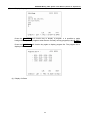
After search, LCD changes to display the page for program restart.
42
GSK983M Milling CNC System User Manual (Volume II: Operations)
The TARTGET POSITION indicates the restarting position of machining.
The DISTANCE TO GO indicates the distance from the current tool position to the
restarting position of machining.
M indicates the M codes instructed in the last 35 times.
T indicates the T codes instructed in the last 2 times.
S indicates the last instructed S code.
B indicates the last instructed B codes.
The first instructed code is indicated.
The program restart command or the running command for eliminating each code in reset
state is also indicated.
(g) Set the program restart switch to OFF.
(h) Observe the page. Output by the MDI panel in MDI mode if the M, S, T and B codes to be
output exist. In this case, the M, S, T and B codes to be output no longer appear on the
program restart page.
(i)
(2)
When the tool moves to the machining restarting position in AUTO mode, check the
distance indicated by DISTANCE TO GO is correct and the tool does not contact
workpiece. Press the RUNNING button after manually moves the tool to the position that
does not contact the workpiece. Now the tool moves to the restarting position in the
sequence of the 4th axis, axis X, axis Y and axis Z and restart machining.
Restart machining (Q type) after the occurrence of the following conditions.
(a) Disconnect the power supply.
(b) Press the EMERGENCY STOP button
(c) The machine immediately stops due to stored stroke limit alarm.
(d) The coordinate system changes after the last automatic operation.
Example:
43
GSK983M Milling CNC System User Manual (Volume II: Operations)
(i)
Specify G92 command through MDI.
(ii) Move the coordinate system.
(iii) Set the automatic coordinate system after returning to the reference point.
(iv) Press the SHIFT button.
(v) Owing to reset, the change of coordinate system, etc.
(a) After switching on or the release of emergency stop and stroke limit alarm, the machine
returns to the reference point before restart (see the Notes below)
(b) The tool is moved to the programmed starting point of machining by manual and the set
modal data and coordinate system is identical with the restart of the machine.
(c) If necessary, set or change the offset.
(d) Set the PROGRAM RESTART button on the operation panel of the machine to ON.
(e) Display the program by pressing the PROGRAM button. Search the required program
when it is not available.
(f)
Return the program to the origin point. Press the cursor
operating mode.
↓
button in automatic
(g) Search the sequence number that the block restarts by pressing the Q and cursor ↓
button and typing in the sequence number.
(h) When the same sequence number appears for many times during search, the higher four
digits are specified as the number of times of sequence number appearance and the
lower four digits as its sequence number.
(i) After search, LCD turns to display the page for program restart.
(j)
Set the program restart switch to OFF.
(k) Observe the page. Output by the MDI panel in MDI mode if the M, S, T and B codes to be
output exist. In this case, they no longer appear on the program restart page.
(l)
When the tool moves to the machining restarting position, check that the tool does not
contact workpiece. If necessary, manually move the tool to the position that does not
contact the workpiece.
(m) Check that the distance indicated by the DISTANCE TO Go is adequate.
(n) Return to the AUTO mode and press the RUNNING button. Now the tool moves to the
restarting position in the sequence of the 4th axis, axis X, axis Y and axis Z and restart
machining.
Note 1: The following conditions, pressing the
cursor ↓ button do not restart the program.
P
button, the sequence number and the
(a) After switching on, no automatic operation is performed.
(b) Automatic operation is performed after the release of emergency stop or stored stroke
limit alarm.
(c) he coordinate system is established, changed or moved (the change in the offset of the
44
GSK983M Milling CNC System User Manual (Volume II: Operations)
origin of the external workpiece). The automatic operation is performed.
The above (a), (b) or 94—97 alarm reset causes P/S 97 alarm.
P/S 94 alarm caused by the establishment of a coordinate system;
P/S 95 alarm caused by the stroke of a coordinate system;
P/S 96 alarm caused by the change of a coordinate system.
The block for the restartable machining is one of the many blocks. The block follows the block
when the coordinate system is last set of changed before the interruption of machinating.
Note 2: In P mode or Q mode, the tool moves to the machining restarting position by stroke by
one axis each time. The stop of a single block is possible after the motion of the axis. However,
manual operation rather than MDI operation can be inserted. The returned axes cannot move.
Note 3: When move signal, offset and other conditions are different from the past, the tool
cannot return to the machining restarting position identical with the past. The single block
switch is set to ON or AUTO mode is switched to for continuous search operation.
Note 4: When feed hold is active during search or reset operation is performed after search, make
sure to carry out program restarting operation from the beginning. After the end of search, however,
the parameter 007 “CLEAR Pos” shall be changed to reset state in MDI mode.
Note 5: Running can be ignored provided that the automatic restart switch of program is set to
ON position.
Note 6: Always bring the manual absolute switch to ON position for manual operation no
matter it is before or after machining.
When a program restarting operation instead of resetting is performed after manual operation
or when manual operation is performed along the axis that has not returned to the machining
restarting position, the concerned motion is performed once the manual absolute switch is set
to ON position regardless that the manual absolute switch is in ON or OFF position.
Note 7: In principle, the tool cannot return to the correct position in the following cases:
(a) The manual absolute switch is brought to OFF position for manual operation.
(b) The tool is moved in the lock state of the machine or after the cancellation of axis Z
command.
(c) Mirror image function is used.
(d) The coordinate system is not set at the beginning of incremental Program edit.
(e) Manual operation is inserted during the return of an axis.
(f)
Machine lock is disabled after the program restart is instructed.
(g) Program restart command is given during the execution of the cutting program with skip or
the blocks of an absolute command.
(h) A coordinate system is established after search. Nevertheless, in the condition of (c) the
return of the tool in P mode in the block executed by setting the mirror image machining
switch to OFF position as well as the blocks that follow. In this case, the mirror image
45
GSK983M Milling CNC System User Manual (Volume II: Operations)
machining state is the same as interruption. No alarm is given in any case.
Note 8: When the specified block only includes M98, M99, macro program calling command
(M65, G66 and G67) or macro program statement, or no specified block is searched, No.60
alarm will be given.
Note 9: When program restarting operation is instructed and G28 is detected without returning
to the reference point after power on or cancellation of emergency stop or stroke limit alarm
(immediate stop), P/S alarm (98) will be resulted in.
Note 10: After the end of search, P/S alarm (99) is given when a move command is executed
through MDI operations before axis motion.
Note 11: After the program restart is instructed, “RSTR blinks at the button of the LCD screen
before the return of the last axis (Z).
Note 12: When the block before the restart block has G28, G30, an command or incremental
command, the absolute position of the 4th axis can be displayed in the range of 360°. In this
case, the 4th axis is an axis of rotation and the direction of returning to the reference point is
negative.
4.4.22 Program number comparison stop function
The function is used to stop machining after an command is executed to the preset sequence
number.
(a) Select the MDI mode.
(b) Press the SET button to display the SET page. Move the cursor to the set number 180 by
pressing the cursor ↑ or ↓ key. The cursor cannot be moved with address N.
(c) Type the command in the sequence of
INPUT.
P , the sequence number to be stopped and
(d) Select the AUTO mode and get ready for operation by setting the machine.
(e) Press the RUNNING button.
The machine stops after the data in the block whose sequence number has been
predetermined in step (c).
The predetermined sequence number is cleared while the machine is stopping.
To perform another comparison stop, repeat the above procedures from (a).
Note 1: Sequence number O cannot be used for comparison stop
Note 2: The predetermined sequence number is cleared by setting.
4.4.23 Display of parameters (function button: PAR)
Press the PARAMETER button to display the parameters, which are laid out in several pages.
Find the desired parameter by pressing the PAGE button (see Appendix 5 for the meanings of
46
GSK983M Milling CNC System User Manual (Volume II: Operations)
parameters).
4.4.24 Program edit
(Function button: PROGRAM)
The function is used to modify the stored programs.
(1) Set the MODE SELECTION switch to EDIT.
(2) Press the PROGRAM button.
(3) Select a program. Proceed with (4) if the program has been selected; otherwise perform
program number search.
(4) Search the words to be modified by scanning or word search.
(5) Modify, insert or delete the words.
Note 1: Definition and edit unit
A word comprises an address and the numeral that follows. For user macro program, however,
the concept of word is indefinite. Hence the concept of “edit unit” is adopted. Edit unit serves
as the object of modification and deletion in a single operation and moves the cursor to its
beginning in a single pass. For data insertion, the data is inserted behind the edit unit.
Definition of edit unit
①
From one address to the next one;
②
An address is a letter symbol: WHILE, GOTO, END, DO, =, or ; (EOB)
According to the definition, a word is also an edit unit. On the basis of the following
explanations about edit, strictly speaking, word shall be called “edit unit”.
Note 2: During program execution, machining is temporarily suspended by single block
skipping, feed hold and other functions. Nevertheless, continuing to execute a program is not
allowed after program modification, insertion and deletion; otherwise the program cannot be
correctly executed as required by program data. Program is displayed on the LCD after
subsequent machining.
To modify stored data in part program edit mode, they must be modified in reset condition
before program execution or when resetting operation is performed after edit.
4.4.24.1 Word scanning
(1)
Press the cursor
↓
button.
47
GSK983M Milling CNC System User Manual (Volume II: Operations)
The cursor moves forward word by word on the screen. The cursor is displayed underneath
the address character of the selected word.
(2)
Press the cursor
↑
button.
The cursor returns word by word on the screen. The cursor is displayed underneath the
address character of the selected word.
Example:
(3)
Continuous search can be conducted by pressing down and holding the cursor
button.
(4)
The next page is displayed and search starts from the beginning of the page by pressing the
page ↓ button.
48
↓
or
↑
GSK983M Milling CNC System User Manual (Volume II: Operations)
(5)
The previous page is displayed and search starts from the beginning of the page by pressing
the page ↑ button.
(6)
Displaying page by page is possible by pressing down and holding the cursor
button.
↓
or
↑
4.4.24.2 Word search
Search a specified word from the present position forward.
N1234×1000
Y1250:X1234:N5678
Present word
Search direction
(1)
Enter
X,
1,
2,
3
M03:
X1234 is the object of search.
and
4
with the keypad.
Note 1: The search that only enters X123 and X1234 with the keypad can not be performed.
Note 2: The search that only enters X9 and X009 with the keypad can not be performed. 009
shall be entered with the keypad for the search of X009.
(2)
Search starts when the cursor
after the search.
↓
is pressed. The cursor is displayed underneath X in X1234
4.4.24.3 Address search
Search a specified address from the present position forward.
N1234×100.0
Y1250:X1234:N5678,
Present word
(1)
Type in
(2)
Search starts when the cursor
search.
M03:
M03 is the object of search.
M.
↓
is pressed. The cursor is displayed underneath M after the
Note 1: Pressing the CANCEL button after typing in a numeral deletes the latter and displays a
blank space. Pressing the CANCEL button only indicates CANCEL.
Note 2: Both word search and address search do not start by pressing the cursor
↑
button.
4.4.24.4 Methods for returning to the beginning of a program
01100 N0001 X12.34: Z15.67: G01×12.5: M04
Beginning
(1)
Present word
Method 1
A program is displayed from its beginning when the RESET button is pressed in EDIT mode.
49
GSK983M Milling CNC System User Manual (Volume II: Operations)
(2)
Method 2
Perform sequence number search.
(3)
Method 3
(a) Set the MODE SELECTION button to AUTO.
(b) Press the PROGRAM button.
(c) Press the cursor
↑
button to return to the EDIT mode for editing a part program.
4.4.24.5 Word insertion (active when the program protection lock is disabled)
Insert T105
N1234×100.0
Y1250:X1234:N5678,
M03:
Object of search
(1)
Quickly search and scan the word preceding the position where a word is to be inserted.
(a) Scan. See 4.24.1.
(b) See 4.24.2 for word search. When Y1250 is in front of the currently indicated position, first
move the cursor to the beginning o the program.
(2)
Type in
T,
1,
0
and
5
and press the INSERT button.
Before insertion
50
GSK983M Milling CNC System User Manual (Volume II: Operations)
After insertion
Note 1: When what is inserted is not an address but a numeral, the inserted number is added
to the word indicated by the cursor. (Edit unit: In the above example, the insertion of 2.5 will
create Y12502.5 when the cursor is underneath Y in Y1250.
Note 2: A numeral can also be added to the behind of all addresses.
E.g. EOB, IF, etc. When the cursor is underneath “;”, the insertion of 23 will create “; 23”.
However, it makes no sense in programming.
4.4.24.6 Word modification (active when the program protection lock is disabled)
N1234×100.0
Y1250:T105: S1234:
To be changed to M15
(1)
Search and scan the word to be modified.
(2)
Type in
M,
1
N1234×100.0
and
5
and press the ALTER button.
Y1250:M15: S1234:
The program is to be modified.
4.4.24.7 Insertion and modification of several words, blocks and strings
Word, block, character string and other information can be inserted (up to 32 characters). In
the foregoing example, to insert T105 M20, type in T105 M20 and press the INSERT button.
51
GSK983M Milling CNC System User Manual (Volume II: Operations)
Before insertion
After insertion
A word indicated by the cursor can be changed to a word, block or a string, etc.
Note 1: When the cursor is underneath Y in Y1250, the insertion of 25 M20 will become Y1250
2.5 M20.
Note 2: When the cursor is underneath Y in Y1250 T105, the insertion of 2.5 M20 will become
Y1250 2.5 M20.
52
GSK983M Milling CNC System User Manual (Volume II: Operations)
4.4.24.8 Word deletion (active when the program protection lock is disabled)
N1234 ×100.0
Y1250
T105: X1234:
(1)
To delete Y1250
Search and scan the word to be deleted.
(2)
Press the DELETE button.
N1234 ×100.0
T105:
X1234:
The program after deletion
4.4.24.9 The deletion of the part before EOB
Present word
N1234 ×100.0
Y1250
T105
M13: X1234:
Range of deletion
Press the EOB and DELETE buttons to delete the part before EOB and move the cursor
to the underneath of the address character of the next word.
4.4.24.10 Deletion of several blocks (active when the program protection lock is disabled)
The range of deletion covers from the currently dedicated word to the block whose
sequence number is specified.
Present word
Enter N2233 with the keypad
N1234 M10;M15×100.0……T0122;N2233 T1200;N3344 Y10.0:
Range of deletion
(1)
Type in the sequence number of the last block to be deleted. Type in
and 3 in this example.
(2)
Press the DELETE button.
N ,
2 ,
2 ,
3
4.4.24.11 Storage sorting
The frequent edit of part program sometimes prevents the storage from economic usage,
resulting in the failure to store the program data whose length is specified. Hence it is
necessary to regularly clean up the storage.
Press the CANCEL and SHIFT buttons in succession in the EDIT mode. After sorting, the
admissible number of characters is indicated at the bottom of the screen.
Note 1: For one program, the storage stores the specified length of the program. For many
programs, some storage areas are used to identify these programs.
Note 2: The storage areas to be modified or inserted that exceed the actual length are
wasted in quick part program edit. Storage sorting may eliminate the waste.
53
GSK983M Milling CNC System User Manual (Volume II: Operations)
4.4.24.12 The indication of all stored program numbers
Once the contents of the storage described in 4.24.11 are sorted, all stored program
numbers are displayed.
4.4.24.13 Edit of user macro program (active when the program protection lock is disabled)
User macro program may be edited using the SHIFT key. Operate the key in EDIT mode
and when the program protection switch is released. The following points shall be observed.
(a)
SHIFT key
Once the SHIFT key is pressed, the cursor (the cursor for keyboard entry: the cursor is in
the position of the character whose data is last input) changes from “—” to “∧”. Press the
key with a character in the lower right angle of the key top in this state. The character in the
lower right angle can be entered.
After entering a character, the cursor restores to the initial “—”. If the SHIFT key is pressed
twice, the cursor also restores the initial “—”.
(Example)
54
GSK983M Milling CNC System User Manual (Volume II: Operations)
(b)
Deletion, insertion and modification of a program
While editing an entered user macro program, the cursor moves at the following locations:
(i) At an address
(ii) At the / of an optional block skipped over
(iii) At the left beginning # of a substitution statement
(iv) At (·=)OR;
(v) At the leading character of IF, WHILE, GOTO, END or DO
On the LCD screen, there is a blank space for a character before the above characters.
Deletion, modification and insertion may be performed between the front and rear cursor
positions.
(Example) Cursor position
N001x-#100: #1=123; N002 / 2x[12/#3]:
N003x-SQRT[#3/3*[#4+1]]: N004x-# 2 Y#1:
N005#5=1+2-#10; IF[#1 NE 0]GOTO 10:
WHILE[#2LE·B]D01: #[2000+#2]=#2*10:
#2=#2+1:
END1:
(Note 1) The cursor cannot be stopped in (
).
Control OUT/IN
(Example)(#1=100):
The cursor cannot stop here.
(Note 2) The position of the cursor can change with the changed program.
(Example) X100 Y200: before program modification:
If Y200 is changed into 100 with the ALTER key, it will become X100 100:
(c)
Abbreviations of macro program word
To change or insert a macro program word, it can be abbreviated to its first two characters.
The underlined part can alternate the word as an abbreviation.
WHILE, GOTO, END, XOR, AND, SIN, COS, TAN,
ATAN, SQRT, ABS, BCD, BIX, FUP, ROUND.
(Example): When WH[TA[#1*AB[#2]]LERO[#3]] is entered as data of keyboard entry, the
actual entry will be:
WHILE[TAN[#1*ABS[#2]]LEROUND[#3]]
55
GSK983M Milling CNC System User Manual (Volume II: Operations)
4.4.25 Indication of running time
Automatic operating time can be accumulated and displayed in hour, minute and second
(increment of 2sec) on the screen.
Time is displayed as indicated in the picture below when the SET button is pressed. Press
the PAGE button for other pages.
Note 1: The accumulated time includes automatic operating time but not the single block
off-time, feed hold off-time, etc.
Note 2: If the power supply is switched off immediately after the stop of automatic operation, a
time error up to 6min may be caused after power on again.
Note 3: When necessary, time can be preset through setting operations. The data number is
57, 58 or 59.
4.4.26 Menu switching function
It is possible to enable or disable the switching function of the NC storage using the LCD
instead of the operation panel of the machine.
With this function, the number of switches on the operation panel can be reduced. The
following signals may be switched on or off through the LCD.
(1) Single block (SBK)
(2) Machine lock (MLK)
(3) Dry run (DRN)
(4) Optional block skip 1 to 9(BDT1—9)
56
GSK983M Milling CNC System User Manual (Volume II: Operations)
(5) Mirror image (MIX, MIY, M14 and M15)
(6) Display lock (DLK)
(7) Auxiliary function lock (AFL)
(8) Axis Z neglected (ZNG)
(9) Manual absolute (ABS)
After the signal data is stored in memory, the switching of these data displayed on the LCD
remains unchanged even the NC power is disconnected.
These signals are not completely replaced by those displayed on the LCD. These signals are
deemed to be switched on no matter whether the machine signals or the signals set on the
LCD are switched on. Accordingly, these signals can be switched on or off through the LCD
by disconnecting the above listed optional signals through the operation panel.
Setting and display: The LCD state of the above signals may be displayed through the
following operations.
Display
(i)
Select the set chapter 3
For setting display, press the SET button and then press it twice again.
(ii) Press the PAGE button to select the desired page from the two pages than can be
displayed.
Page 1: The part other than optional blocks skipping
Page 2: Optional block skipping 1~9.
Setting
Proceed as follows after the above procedures.
(iii) Move the cursor to the page number to be changed.
Move the cursor to the page number to be changed by pressing the cursor ↑ or ↓ key.
(iv) When the address P is pressed, enter 1 for switching on and 0 for switching off. Press
the keys in the sequence of (P)
(entry).
1
2
57
GSK983M Milling CNC System User Manual (Volume II: Operations)
4.4.27 Operations of LCD soft function keys
4.4.27.1 General
Here function buttons (POSISTION, PROGRAM, OFFSET etc) are used as soft function
keys. Their meanings may be displayed on the LCD. All the pages abstained by pressing the
soft function keys are described below.
4.4.27.2 Display
(1)
Display of actual position
58
GSK983M Milling CNC System User Manual (Volume II: Operations)
The actual position of relative coordinate system is displayed on the LCD when the soft
function key RELATIVE is pressed.
Press the page ↓ key the update display as shown above. The positions of workpiece
coordinate system and relative coordinate system are exchangeable on the screen.
59
GSK983M Milling CNC System User Manual (Volume II: Operations)
(2)
Display of a program
Press the PROGRAM soft function key to display a program. It is possible to make
background edit (edit the programs other than the currently running programs) using B. EDIT.
Press the PROGRAM soft function key again to display program list. The program list is
displayed as follows.
(3) Display of offsets
60
GSK983M Milling CNC System User Manual (Volume II: Operations)
When the OFFSET soft function key is pressed, the offset corresponding to each tool number
is indicated on the LCD. Press the page ↑ or ↓ key and cursor ↑ or ↓ key to
select the desired data. At the same time, the actual position of relative coordinate system is
displayed on the lower part of the LCD.
(4)
Display of a command
Press the COMMAND soft key. The data displayed on three pages of the LCD appears on the
screen as shown in the above figure. The screen changes as follows when the page ↓ key
is pressed.
61
GSK983M Milling CNC System User Manual (Volume II: Operations)
(5) Setting
62
GSK983M Milling CNC System User Manual (Volume II: Operations)
Press the SET soft function key. Now all set data is displayed on the screen. Running time is
displayed in the page of SET DATA 01.
63
GSK983M Milling CNC System User Manual (Volume II: Operations)
Press the MACRO key. Now the local variable and common variable of user macro program
are displayed on the LCD screen.
Press the SWITCH key. The menu switch window is displayed as shown as shown in Section
4.26 (menu switch function).
(6)
Display of alarm and operation information
Pressing the ALARM soft function key displays the alarm messages as shown in the above
figure. Pressing the OUTMESS soft function key displays the external information as shown
in the above figure.
64
GSK983M Milling CNC System User Manual (Volume II: Operations)
(7)
Parameter display
Pressing the NC PARAMETER and PC
relevant parameters on the LCD.
Pressing the page
(8)
↑
or
↓
PARAMETER soft function keys to display the
and cursor
Display of diagnostic data
65
↑
or
↓
to display the desired parameters.
GSK983M Milling CNC System User Manual (Volume II: Operations)
Pressing the DIAGNOSIS soft function key displays 64 diagnostic data.
Pressing the page ↑ or ↓ and cursor ↑ or ↓ to display the desired diagnostic data.
4.4.27.3 Direct entry of measured workpiece origin offset
The coordinates of the relative coordinate system that offsets at the workpiece origin and is
indicated by the LCD screen may be set as workpiece origin offset. With the function the
relative coordinate system is cleared away at the reference point and the machine is moved
to the workpiece origin by manual. Now the coordinates of the relative coordinate system
may be set as workpiece origin offset. In this way it is easy to set the workpeice origin offset.
(1)
Operating procedures
The relative coordinate system may be cleared away and workpiece origin offset set on the
workpiece origin offset page of the LCD through the following procedures.
(a) Delete the relative coordinate system
Pressing the X and SHIFT keys deletes the relative coordinate system of axis X (this
operation accordingly applies to axes Y and Z as well as the 4th and 5th axes).
(b) Set workpiece origin offset
Press the X and INPUT keys after moving the cursor to the required workpiece offset
number. Then the coordinates of the axis X in the corresponding coordinate system is
set as the axis-X workpiece origin offset of the selected workpiece offset number.
(This operation accordingly applies to axes Y and Z as well as the 4th and 5th axes
Note: When the
system blinks.
X
key is pressed in steps (a) and (b), the X of the relative coordinate
4.5 Position indication through position display unit (available upon customer’s request)
The position display unit indicates the actual position. The position display reset buttons are
connected to the position display unit. Each button corresponds to one axis. The position
66
GSK983M Milling CNC System User Manual (Volume II: Operations)
display of the relevant axis is cleared when any one of the buttons is pressed.
After the absolute origin (G92) is programmed and established, it is indicated on the display
unit through parameter setting (PPD) coordinates.
Note 1: Position pulse cannot be sent to the position display unit when the DISPLAY LOCK
switch is set to ON position. The switch may used to prevent writing offset in position
indication by manually moving the coordinate system.
Note 2: Position is indicated in Inch-system format in the event of entry in inch system.
Position is indicated in metric format in the event of entry in metric system. The RST button
shall be pressed so that the position indication is zero when the input system is switched from
inch system to metric system, vice versa.
Note 3: Machine compensation data, e.g. amount of clearance compensation cannot be
indicated on the position display unit.
67
GSK983M Milling CNC System Operating Manual (Volume II: Operations)
Appendix 1: Codes for programming
ISO Code
Character
8
7
0
6
5
EIN Code
4
3
2
1 Character
3
○
2
○
2
○
○ ○
○
○
○ ○
○
○ ○ 3
○ ○
○ ○
4
5
○ ○
○ ○
○ 5
6
○ ○
○ ○ ○
6
○ ○ ○ ○ 7
7
○
○ ○
8
○
○ ○ ○ ○
8
○ ○ ○ ○
○ 9
○ a
○
○
○
○
○
○
○
○
○
○
○
○
○
"6
○
"7
"8
"9
○
○
○
Address A
○
○
○
○
○ ○
C
○ ○
○
○ ○ c
○ ○
D
○
○ ○
d
○ ○
E
○ ○
○ ○
○ e
○ ○
F
○ ○
○ ○ ○
f
○ ○
G
○
○ ○ ○ ○ g
○ ○
H
○
○ ○
I
○ ○
○ ○
J
○ ○
○ ○
○
K
○
○ ○
L
○ ○
○ ○ ○
M
○
○ ○ ○
N
○
○ ○ ○ ○
O
○ ○
P
○
○
○
p
○
○
Q
○ ○
○
○
○ q
○
○
R
○ ○
○
○
○
r
○
S
○
○
○
○ ○ s
○
T
○ ○
○
○ ○
t
○
U
○
○
○ ○
○ u
○
V
○
○
○ ○ ○
v
W
○ ○
○
○ ○ ○ ○ w
X
○ ○
○ ○ ○
x
○
○
Y
○
○ ○ ○
○ y
○
○
Z
○
○ ○ ○
z
○
○
○
○ i
○
○
j
○
○ ○ k
○
l
○
○
? "B
○
? "C
"D
○
○
○
○
○
○
○
○
○
○
○
○
○
"E
"F
○
"G
? "H
○
○
○
○
○
"I
○
○
○
? "J
○
○
○
○
○
○
○
○
○
○
○
○
○
○
○
○
○
○
○
○
○
○
○
○
○
○
○
○
○
○
○
○
○
○
○
○
○
○
○
○
"P
"R
"S
○
"T
"U
○
○
"N
"O
○
○
○
"L
"Q
○
○
○
○
○
○
"K
"M
○
○ ○
68
"5
○
b
○ ○ ○ ○ ○ ○ ○ ○ ○ DEL
○
○
○
○
"4
○
○
○ ○ ○ ○ ○ o
"3
○
○
n
○
○
B
○
○
"1
"2
○
○
○
○ m
○
○
○
h
1
Numeral “0”
○
○
○
2
○
A
DEL
Meaning
4
○ 1
0
9
5
0
○ ○
○
6
0
○
4
7
○ ○
1
3
8
○
? "V
"W
○
"X
? "Y
○
○
○
○
"Z
* Delete
GSK983M Milling CNC System Operating Manual (Volume II: Operations)
ISO Code
Character
8
7
6
5
EIN Code
4
3
2
1 Character
NUL
8
7
6
5
Meaning
4
3
2
1
No-hole
Blank
0
0
*
and
EIA
codes are not used in
effective-value
information area
BS
○ 0
○
HT
○ 0
LForNL
○ 0
○ 0
○ Tab
○
○
SP
○
○
0
%
○
○
0
○
○ 0
○
○ 0
○
+
○
○ 0
○ ○ +
-
○
○ 0
)
○
:
/
○
○
$
&
○
’
○
○
0
○
0
○
○ ER
(2-4-3)
○
○
(2-4-7)
○
○
○ -
* Rewind ( backspace )
○
* Separator
0
○
○
○
○
○
○
End of block
0
* Return of printer base
0
* Blank space
○
0
○
○
0
○
○
0
○
○
Control OUT (start of
note)
Control IN (end of
note)
0
○
* Positive sign
0
○
Negative sign
As a program number
0
○
/
End of rewinding
of ISO codes
of
○ 0
○ ○ ○
○
○ 0
○ ○
○
0
○
0
○
○
0
○ ○
○
0
○ ○ ○
0
* Apostrophe
○
0
* Asterisk
○
○
○ 0
,
○
○
○ 0
;
○
○ ○ ○ 0
○
·
○
0
Stop
○
*
<
○
SP
○ ○ ○ 0
·
#
○
CRorEOB
CR
(
○
BS
○
○
○
○ ○
○
&
○
○
,
○ ○
○ ○ ○ 0
○
○
○
○
0
○
○
selection
Full
stop
* Well number
0
* Unit number
0
○
* & (and)
○
○
(decimal
point)
0
0
block
○
* Comma
0
* Semicolon
0
* Left angular bracket
0
* Equal sign
=
○
○ ○ ○ 0
○
>
○
○ ○ ○ 0
○ ○
0
* Right angular bracket
○ ○ ○ 0
○ ○ ○
0
* Question mark
0
* @ sign
○
0
* Quotation mark
○ ○
0
* Left brace
○
0
* Right brace
?
@
0
○ ○
○
”
○
0
[
○ ○
○ ○ 0
]
○ ○
○ ○ 0
○
69
GSK983M Milling CNC System Operating Manual (Volume II: Operations)
(Note 1) “*” code is read in memory only it appears in a note and is invalid in other information
areas.
(Note 2) “?” code is read in memory only it appears in a note and causes alarm when it
appears in other information areas.
(Note 3) When a user macro program is selected, the following codes are usable in the
effective information areas.
For ISO: +, [, ], #, *, =, B, C, H, J, V, Y.
For EIA: +, [, ], &, the codes set by parameter and B, C, H, J, V, Y.
(Note 4) The codes not listed in the table are ineffective even its parity is correct.
(Note 5) The use of a code with incorrect parity may cause TH alarm. But it is ignored in notes
and does not cause TH alarm.
(Note 6) The output of all the eight digits does not cause alarm for EIA code.
70
GSK983M Milling CNC System Operating Manual (Volume II: Operations)
Appendix 2 G codes list
G Codes
G00*
G01*
G02
G03
G04
G07
G09
G10
Group No.
01
00
G17*
G18
G19
G20
G21
G22
G23
G27
G28
G29
G30
G31
G33
G40*
G41
G42
G43*
G44*
G49*
G45
G46
G47
G48
G50*
G51
G54*
G55
G56
G57
G58
G59
G60
G61
G62
G64*
02
06
04
00
01
08
00
11
14
00
15
Function
Positioning (rapid traverse)
Linear interpolation (feed)
Circular interpolation CW (clockwise)
Circular interpolation CCW (counterclockwise)
Dwell
Feedrate sine curve control (imaginary axis)
Exact stop check
Offset value setting, workpiece zero offset setting
XY plane selection
ZX plane selection
YZ plane selection
Input in inch
Input in mm
Stored stroke limit ON
Stored stroke limit OFF
Reference point return check
To return to reference point
To return from reference point
To return to the 2nd, 3rd and 4th reference points
Skip cutting
Thread cutting
Tool nose radius compensation cancel
Tool nose radius compensation left
Tool nose radius compensation right
Tool length compensation + direction
Tool length compensation - direction
Tool length compensation cancel
Tool offset increase
Tool offset decrease
Tool offset double increase
Tool offset double decrease
Scaling OFF
Scaling ON
Workpiece coordinate system 1 select
Workpiece coordinate system 2 select
Workpiece coordinate system 3 select
Workpiece coordinate system 4 select
Workpiece coordinate system 5 select
Workpiece coordinate system 6 select
Single direction positioning
Exact stop check mode
Automatic corner override
Cutting mode
71
GSK983M Milling CNC System Operating Manual (Volume II: Operations)
G65
G66
G67*
G73
G74
G76
G80*
G81
G82
G83
G84
G85
G86
G87
G88
G89
G90*
G91*
G92
G94*
G95
G96
G97*
G98*
G99
00
2
09
03
00
05
13
10
User macro simple call
User macro modal call
User macro modal call cancellation
Peck drilling cycle
Counter tapping cycle
Fine boring
Canned cycle cancel
Drilling cycle, spot boring
Drilling cycle, counter boring
Peck drilling cycle
Tapping cycle
Boring cycle
Boring cycle
Back boring cycle
Boring cycle
Boring cycle
Absolute programming
Incremental programming
Coordinate system setting
Feed per minute
Feed per rotation
Constant surface speed control
Constant surface speed control cancel
Return to initial point in canned cycle
Return to R point in canned cycle
(Note 1) The G codes marked with * are the initial G codes of all groups. That is, these G codes are
established when power on or pressing the RESET key (the system parameters specifying
initial G codes are validate).
The selection of the state of the initial G codes such as G00, G01, G43, G44, G49, G90, G91
or G94 and G95 shall be set by parameters (G00, G43, G44, G90 and G95).
For G20 or G21, it becomes the state before power off.
(Note 2) The G codes in group 00 are modal and are only valid in the blocks they belong to.
(Note 3) When a G code not listed in the above table is specified or an optional G code not defined by
control unit is specified, (N0.010) will give an alarm. (N0.010) But G38 and G39 are ignored.
(Note 4) Some G codes may be specified in the same block even they do not belong to the same
group. When 2 or more G codes than belong to the same group are specified in a block, the
lastly specified G code will be valid.
(Note 5) If any G code in group 01 in fixed cycle mode, the fixed cycle will be automatically disabled
and the system will be in G80 state. However, the G codes in group 01 are not subject to the
influence of the G codes of fixed cycle.
(Note 6) G70 and G71 replaces G20 and G21 (special G codes) by parameter setting (GSP).
72
GSK983M Milling CNC System Operating Manual (Volume II: Operations)
(Note 7) The G codes of all groups are displayed.
73
GSK983M Milling CNC System Operating Manual (Volume II: Operations)
Appendix 3: Ranges of command values
Input in mm
Output in mm
Input in inch
Output in mm
Input in mm
Output in inch
Input in inch
Output in inch
0.001mm
0.001°
0.0001inch
0.001°
0.001mm
0.001°
0.0001inch
0.001°
Maximum stroke (the value
starts from reference point)
±99999.999mm
±99999.999mm
±3937.0078inch
±99999.999inch
Max. command value
±99999.999mm
±99999.999°
±3937.0078inch
±99999.999°
±99999.999mm
±99999.999°
±99999.999inch
±99999.999°
1 mm/min
to 15000
mm/min
0.01 inch/min to
600.00
inch/min
1 mm/min to
15000
mm/min
0.01 inch/min to
600.00
inch/min
30 mm/min to
15000
mm/min
30 mm/min to
15000
mm/min
3.0 inch/min to
600.0
inch/min
3.0 inch/min to
600.0
inch/min
6 mm/min to
15000
mm/min
6 mm/min to
15000
mm/min
0.6 inch/min to
600.0
inch/min
0.6 inch/min to
600.0
inch/min
1 mm/min to
2000
mm/min
0.04 inch/min to
78.7
inch/min
0.5 mm/min to
1016
mm/min
0.02 inch/min to
40
inch/min
Coordinates of 2nd reference
point (the value starts from
reference point)
0 mm to ±
99999.999mm
0 mm to ±
99999.999mm
0 inch to
±3937.0078inch
0 inch to
±99999.999inch
Tool offset
0 mm to ±
99999.999mm
0 inch to ±
99999.999inch
0 mm to
±99999.999mm
0 inch to
±99999.999inch
0.001mm
0.0001inch
0.001mm
0.0001inch
0mm to 0.255mm
0 mm to
0.255mm
0 inch to
0.255inch
0 inch to
0.255inch
Compensation of screw pitch
error
0mm to
±0.007mm
0mm to
±0.007mm
0inch to
±0.007inch
0inch±0.007inch
Setting range of stored stroke
limit (the value starts from
reference point)
0mm to ±
99999.999mm
0mm to ±
99999.999mm
0inch to
±3937.0078inch
0inch to
±99999.999inch
0s to 99999.999s
0s to
99999.999s
0s to 99999.999s
0s to
99999.999s
Least setting unit
When
adjusting
cutting feed
by 100%
Feed per minute
Feedrate at high speed (all axes
are independent)
Upper limit of cutting feedrate
Manual feedrate
F0
JOG feedrate
Least value of incremental feed
Clearance compensation
Pause
74
GSK983M Milling CNC System Operating Manual (Volume II: Operations)
Appendix4 Calculating chart
A4.1
The tool path in a turning angle section
(1 )
Summary
Due to the delay of servo system (as a result of exponential deceleration/acceleration during
cutting or the use of the positioning system of a DC servo motor), a minor deviation exits
between the tool path (tool center path) and instructed path as shown in Fig. 4.1 (a). In this
center, the time constant T1 of exponential deceleration/acceleration is fixed to 0.
Fig. 4.1 (a): The tool path regarding a turning angle section
The tool path depends on the following parameters:
(a) Feedrate (V1, V2)
(b) Degree of the turning angle (θ)
(c) Time constant (T1)(T1 = 0) of exponential deceleration/acceleration during cutting
(d) Loop gain of positioning system
(e) Existence of buffer
This document makes theoretical analysis of tool path with the above parameters. The tool
path of temporarily set parameters is displayed in graph.
The above notes shall be observed for programming. Note whether the machining shape is
within the desired accuracy range.
That is, when it is possible to reach the theoretical accuracy, hold for a proper time using the
suspension function until the command speed drops to zero before reading in the next block.
(2)
Analysis
In the following conditions, make analysis of the tool path as shown in Fig. 4.1(b).
(a) Feedrate remains constant in the blocks before and after the turning angle.
(b) The control is provided with a buffer (error changes with the reading rate of the input
equipment and the number of characters of the next block).
75
GSK983M Milling CNC System Operating Manual (Volume II: Operations)
VX1 = V·cosφ1
VY1 = V·sinφ1
VX2 = V·cosφ2
VY2 = V·sinφ2
π-(φ1-φ2)=θ
[Explanations for the symbols]
V:
Feedrate in the blocks before and after turning angle
VX1: X component of the feedrate in the previous block
VY1: Y component of the feedrate in the previous block
VX2: X component of the feedrate in the next block
VY2: Y component of the feedrate in the next block
θ:
Angle of the turning angle
φ1: The included angle between the direction of the command path in the previous block
and axis X
φ2: The included angle between the direction of the command path in the next block and
axis X
76
GSK983M Milling CNC System Operating Manual (Volume II: Operations)
Calculation of initial value
The initial value at the beginning of a turning angle, i.e. the X and Y coordinates at the end of
the distribution of the control unit are determined by the time constant of the positioning
system of the used DC motor.
X0 = Vx1(T1+T2)………(1)
Y0 = Vy1(T1+T2)………(2)
T1: Time constant (T1 = 0) of exponential deceleration/acceleration
T2: Time constant (reciprocal of position loop gain) of positioning system
Analysis of tool path
The feedrates in the directions of axis X and Y in the turning angle are expressed in the
following formulas.
Vx(t)=(Vx2-Vx1)[1-
⎡
= Vx2 ⎢1 − Vx1
⎢⎣ T1 + T2
Vy(t)=
Vy1 − Vy 2
T1 − T2
⎛
⎞
⎛
⎞
Vx1
{T1 × exp⎜⎜ − t ⎟⎟ − T2 × exp⎜⎜ − t ⎟⎟ } + Vx1]
T1 − T2
⎝ T1 ⎠
⎝ T2 ⎠
⎞⎫⎪⎤
⎟⎟⎬⎥
⎠⎪⎭⎥⎦
……………………(3)
⎧⎪
⎛ t ⎞⎫⎪
⎛ t ⎞
⎨T1 × exp⎜⎜ − ⎟⎟ − T2 × exp⎜⎜ − ⎟⎟⎬ + Vy 2
⎪⎩
⎝ T2 ⎠⎪⎭
⎝ T1 ⎠
……………………(4)
⎧⎪
⎛ t ⎞
⎛ t
⎨T1 × exp⎜⎜ − ⎟⎟ − T2 × exp⎜⎜ −
⎪⎩
⎝ T1 ⎠
⎝ T2
The coordinates of the tool path at time t are calculated with the following formula.
t
X(t)= ∫0 Vx(t )dt − X 0
=
⎛ t
⎛ t ⎞
Vx 2 − Vx1 ⎪⎧ 2
2
⎨T1 × exp⎜⎜ − ⎟⎟ − T2 × exp⎜⎜ −
T1 − T2 ⎪⎩
⎝ T2
⎝ T1 ⎠
⎞⎫⎪
⎟⎟⎬ − Vx 2 (T1 + T2 − t ) ……………(5)
⎠⎭⎪
t
Y(t)= ∫0 Vy (t )dt − Y0
=
A4.2
Vy 2 − Vy1
T1 − T2
⎧⎪ 2
⎛ t
⎛ t ⎞
2
⎨T1 × exp⎜⎜ − ⎟⎟ − T2 × exp⎜⎜ −
⎪⎩
⎝ T2
⎝ T1 ⎠
⎞⎫⎪
⎟⎟⎬ − Vy 2 (T1 + T2 − t ) ……………(6)
⎠⎪⎭
Error of radius direction during arc cutting
When using a DC servomotor, a delay is produced between the input and output axes due to
the factors of the positioning system. The linear interpolation on command path does not
cause any error. Arc interpolation, especially the arc cutting at high speed may cause a
deviation in the direction of radius, which is determined with the following formula.
△Y: Maximum radius error (mm)
V: Feedrate (mm/sec)
77
GSK983M Milling CNC System Operating Manual (Volume II: Operations)
r: Arc radius (mm)
T1: Time constant (sec) (T1 = 0) of exponential deceleration/acceleration during cutting
T2: Time constant (sec) (reciprocal of position loop gain) of positioning system
△
r=
(
)
V
1 2
T1 + T22 × 2
2
r
……………………………………………… (1)
The radius r(mm) and permissible error △ r(mm) of a workpiece are given in actual
machining. Permissible speed limit V(mm/sec) can be calculated with the formula (1).
The Time constant of deceleration/acceleration during cutting set by the unit varies with
machine types. Refer to the user manual supplied with the machine.
78
GSK983M Milling CNC System Operating Manual (Volume II: Operations)
Appendix 5: Parameters
Display and setting procedures of parameters
When the NC is connected to a servo motor or the machine, the specifications and functions
of the machine shall be set to maximize the performance of the servo motor. Since its
contents vary with machine types, please refer to the additional parameters of the machine.
End user is not allowed to change the parameters.
A5.1
Display of parameter
(a) Press the PARAMETER key.
(b) Select the desired page with the PAGE key, or
A5.2
N
, parameter number and INPUT
Setting of parameter
Setting through MDI
(a) Switch the PRM.WT switch on the main unit to ENABLE (ON) to activate the warning
indicator on the panel.
(b) Set the MDI mode.
(c) Press the PARAMETER key.
(d) Press the N , the parameter number to be set and INPUT. The cursor will appear
underneath the number provided that the page of the parameter number to be set is
selected. (This may also be done with the PAGE button and cursor ↓ or ↑ button. )
(e) Set with
P , set data and INPUT.
In the event of error during typing in, press the CANCEL key.
(f)
Make sure the setting is correct.
(g) After the setting of all parameters and end of confirmation, return the switch on the main
PCB to DISABLE (OFF).
(h) To terminate the alarm state (No. 100), press the RST button.
A5.3
Parameters list
Parameter No.
0
0
6
ORWD
7
SCTO
6
EENB
OTCS
FMIC
5
4
3
MDL
MIC
2
1
SCW
0
ORWD: Retention parameter
SCTO 1:
0:
Perform detection of speed reaching signal during command and changing from
quick speed to cutting feed.
Not perform detection of speed reaching signal.
79
GSK983M Milling CNC System Operating Manual (Volume II: Operations)
EENB 1:
0:
OTCE 1:
Servo OFF signal is active.
Servo OFF signal is inactive.
Stop once the stroke switch of hardware is pressed.
(Mechanical position is lost)
FMIC
MDL
MIC
SCW
0
0:
Slow down and stop once the stroke switch of hardware is pressed. (Mechanical
position is not lost)
1:
When inputting in metric system, the unit of feedrate is 1/10.
0:
Not 1/10
1:
The least unit of the indication on the position display unit is 0.01mm or input in
metric system and 0.001inch for input in inch system.
0:
The least setting unit of the indication on the position display unit is 0.001mm or
input in metric system and 0.001inch for input in inch system.
1:
The least setting unit of the indication on the position display unit is 0.01mm or
input in metric system and 0.0001inch for input in inch system.
0:
The least setting unit of the indication on the position display unit is 0.001mm or
input in metric system and 0.0001inch for input in inch system.
1:
The least stroke unit is 0.0001inch (machine in inch system)
0:
The least stroke unit is 0.001mm (machine in metric system)
0
7
ADFT
7
ADET 1:
EOM
CINP
EOM
CINP
6
5
DCS
CLER
4
3
TVC
2
PPD
1
RDRN
0
Perform automatic drift compensation
0:
Not perform automatic drift compensation.
1:
If M30 is sent to the machine side and FIN returns when M30 is instructed, it is
continuously executed from the preceding block of the program, or the machine
side does not send back FIN signal but external reset signal. The program
returns to the beginning to enter into reset state (in automatic mode).
0:
When M30 is instructed, only M30 is sent out to the machine side and the
program does not return to the beginning unless reset and rewinding signal is
used (in automatic mode).
1:
Command speed reduces to 0 between two non-cutting blocks. The next block is
not continued until the machine confirms that the designated position is reached
(the confirmation is called positioning detection).
0
The next block is executed once the command speed reduces to 0 between two
non-cutting blocks (not perform positioning detection).
80
GSK983M Milling CNC System Operating Manual (Volume II: Operations)
DCS
1:
The start button on the MDI panel does not pass through the machine side, but
directly is switched on the NC side (only for MDI mode).
0:
The start button on the MDI panel is sent to the machine side, and then the start
button on the machine side returns for start.
CLER 1:
The NC is brought into clearing state (see Appendix 7 for clearing state) using
the RST button, external reset signal, reset and rewinding signal.
0:
The NC is brought into reset state using the RST button, external reset signal,
and reset and rewinding signal.
1:
Not perform TV check in the control output section (note section)
0:
Perform TV check in the control output section (note section)
1:
Preset the position display unit by setting a coordinate system.
0:
Not preset the position display unit during the setting of a coordinate system.
TVC
PPD
RDRN 1: Dry running is also valid for rapid feed command.
0:
0
0
Dry running is not valid for rapid feed command.
8
ICR
GSP
7
ICR
GSP
G90
G95
G00
6
5
G44
G90
G95
G43
G00
4
3
2
1
0
1:
When ISO code is used for output, EOB will be output by LF.
0:
When ISO code is used for output, EOB will be output by LFCR CR.
1:
Use a special G code.
0:
Use a standard G code.
1:
Enter into G90 mode when in power on and clearing state.
0:
Enter into G91 mode when in power on and clearing state.
1:
Enter into G95 mode when in power on and clearing state.
0:
Enter into G94 mode when in power on and clearing state.
1:
Enter into G00 mode when in power on and clearing state.
0:
Enter into G01 mode when in power on and clearing state.
G44, G43
G44
G43
Initial state
1
0
Enter into G44 mode when in power on and clearing state.
0
1
Enter into G43 mode when in power on and clearing state.
0
0
Enter into G49 mode when in power on and clearing state.
81
GSK983M Milling CNC System Operating Manual (Volume II: Operations)
0
0
9
FIX2
RWL
MCF
6
5
7
FIX2
RWL
MCF
FMFS
FCUT
4
3
0
Not output the M code but SSP and SRV in a fixed cycle (fixed cycle II)
1:
Store the outside of the stroke limit 2 as a prohibited area.
0:
Store the inside of the stroke limit 2 as a prohibited area.
1:
Output EF at the end of the positioning of G81 (axis Z does not move).
0:
Output EF at the end of the positioning of G81 (axis Z moves).
Output FMF signal once in a fixed cycle.
FCUT 1:
The stroke of the axes X and Y in a fixed cycle uses the G codes in Group 01.
0:
The stroke of the axes X and Y in a fixed cycle usually uses rapid feed.
1:
Change the initial plane points with the RESET button.
0:
Not change the initial plane points even using the RESET button.
1:
Output EF with a photoelectric coupler
0:
Output EF with a relay.
TDRN 1:
0:
1
Also valid for dry running of thread cutting.
Valid for dry running of thread cutting.
0
TCW
CWM
SOV
7
6
5
Signs for TCW, CWM and S4-digit output
SOV
1
2
0:
0:
0
TDRN
Output the M code in a fixed cycle (fixed cycle II).
Output FMF signal twice in a fixed cycle.
EFRI
EFR1
1:
FMFS 1:
ILVL
ILVL
SLCC
OFSD
SOVC
4
3
2
TCW
CWM
0
0
M03
M04 are positive.
0
1
M03
M04 are negative.
1
0
M03 is positive while M04 negative.
1
1
M03 is negative while M04 positive.
ISOT
1
0
Sign
1:
Enable main axis adjustment.
0:
Disable main axis adjustment.
TLCC 1:
The change of offset in G43 and G44 modes starts to take effect from the next
block.
0:
The change of offset in G43 and G44 modes starts to take effect from the
following H and D codes.
82
GSK983M Milling CNC System Operating Manual (Volume II: Operations)
OFSD 1:
Tool position offset (G45 to G48) uses D code.
0:
Tool position offset (G45 to G48) uses H code.
SOVS 1:
ISOT
0
Spindle adjustment is cindicatored at 100% in tapping.
0:
Spindle adjustment is not cindicatored at 100% even in tapping.
1:
With the stored stroke limit selection, manual rapid feed is valid even returning to
the reference point is not performed.
0:
With the stored stroke limit selection, manual rapid feed is valid unless returning
to the reference point is performed.
1
1
DGNE
7
SETE
6
DECI
SSPB
5
4
DGNE 1:
Enable data output in diagnosis.
0:
Disable data output in diagnosis.
SETE 1:
DECI
VCT
3
SUPM
ADLN
1
0
2
Input setting is possible when the lock key is closed.
0:
Input setting is not possible when the lock key is closed.
1:
Decelerate when the decelerating signal is “1” during the return to reference
point.
0:
Decelerate when the decelerating signal is “0” during the return to reference
point.
SSPB 1:
Spindle stops when the spindle stop input signal (SSP) is “o”.
0:
Spindle stops when the spindle stop input signal (SSP) is “1”.
1:
It is possible to specify tool compensation vector with I, J and K.
0:
It is impossible to specify (general automatically calculate).
VCT
SUPM 1:
0:
ADLN 1:
0:
0
1
Start and cancel type B in tool radius compensation C.
Start and cancel type A in tool radius compensation C. (See this document for
type A/B.)
The 4th axis is used as a linear axis.
The 4th axis is used as an axis of revolution.
2
ZGM4
7
ZGGMZ
6
ZGMY
5
ZGMX
4
ZM4
ZMZ
ZMY
ZMX
3
2
1
0
ZGMX, ZGMY, ZGMZ and ZGM4 are the reference point return modes for axes X, Y and Z
and the 4th axis respectively.
1: magnetic switch mode
0: grid mode
83
GSK983M Milling CNC System Operating Manual (Volume II: Operations)
ZMX, ZMY, ZMZ and ZM4 are the direction of reference point returns as well as the initial
directions of clearance when power on for axes X, Y and Z and the 4th axis respectively.
1:
The direction of reference point return as well as the initial direction of clearance is
negative.
0:
The direction of reference point return as well as the initial direction of clearance is
positive.
(Note 1) For an axis with reference point return function, the direction of reference point
return is identical with the initial direction of clearance. For an axis without reference point
return function, the parameter only has the meaning of initial direction of clearance.
(Note 2) After power on, clearance compensation is made when moving in the direction set
by this parameter.
0
1
3
PSG2
PSG1
7
6
PHS
5
4
3
2
1
0
PSG2, PSG The tooth to spindle ratio of spindle and position coder
Override
PSG2
PSG1
X1
0
0
X2
0
1
X4
1
0
X5
1
1
Override=
When in PHS and PSCG modes (rotary transformer and induction synchronizer), the initial
setting of relative offset:
1:
does not automatically set phase deviation
0:
automatically sets phase deviation. PHS automatically changes to “1” after the setting is
performed once.
0
1
4
DMR
7
0
1
5
1
5
6
6
6
Z
3
2
1
0
1
0
1
0
Y
2
GRD
4
84
3
X
2
GRD
4
5
3
Y
5
DMR
7
GRD
4
DMR
7
0
6
X
Z
GSK983M Milling CNC System Operating Manual (Volume II: Operations)
0
1
DMR
7
7
4
1
6
5
0
6
GRD
4
DMR
7
4
3
5
5
2
GRD
4
4
3
2
1
0
1
0
5
DMRX, DMRY, DMRZ, DMR4 and DMR5 are the measuring override ratio for axes X, Y and
Z and the 4th axis respectively.
Overrides
Setting codes
Pulse coder
Rotary transformer and induction
synchronizer
0
0
0
1/2
1/8
0
0
1
1
1/4
0
1
0
1
1/4
0
1
1
2
1/2
1
0
0
3/2
3/8
1
0
1
3
3/4
1
1
0
2
1/2
1
1
1
4
1
GRDX, GRDY, GRDZ, GRD4 and GRD5 are the capacities of the reference counters for axes
X, Y and Z and the 4th axis respectively.
Setting codes
Capacity of a cycle
0
0
0
1
2000
0
0
1
0
3000
0
0
1
1
4000
0
1
0
0
5000
0
1
0
1
6000
0
1
1
1
8000
1
0
0
1
10000
(Note) The codes other than those listed in the above table are treated as 8000 capacity.
0
1
8
CPF2
CPF1
3
2
1
0
Pulse frequency (holoaxial calling) for CPF2 and CPF1 clearance compensations.
Frequency, KHZ
CPF2
CPF1
32
0
0
64
0
1
128
1
0
256
1
1
0
1
9
(Must be set to 256KHZ)
TMF
7
6
TFIN
5
4
85
3
2
1
0
GSK983M Milling CNC System Operating Manual (Volume II: Operations)
TMF The time from the send-out of M, S, T and B codes to that of MF, SF, SF and TFBF:
16—126ms (16ms interval).
TFIN The time of FIN signal receiving width: 16—265ms (16ms interval).
TMF
15m
32m
48m
64m
80m
96m
112m
128m
144m
160m
176m
192m
208m
224m
240m
256m
0
CLSI
2
0
TFIN
>15m
>15m
>15m
>15m
>15m
>15m
>15m
>15m
>15m
>15m
>15m
>15m
>15m
>15m
>15m
>15m
sec
sec
sec
sec
sec
sec
sec
sec
sec
sec
sec
sec
sec
sec
sec
sec
CLSI
Setting
0
0
0
0
0
0
0
0
1
1
1
1
1
1
1
1
sec
sec
sec
sec
sec
sec
sec
sec
sec
sec
sec
sec
sec
sec
sec
sec
ZTN5
1:
7
6
5
4
Not detect servo position circuit LSI.
0:
Detect servo position circuit LSI.
ZTN4
ZTNZ
3
0
1
0
1
0
1
0
1
0
1
0
1
0
1
0
1
0
0
0
0
1
1
1
1
0
0
0
0
1
1
1
1
0
0
1
1
0
0
1
1
0
0
1
1
0
0
1
1
ZTNY
ZTNX
2
1
0
ZTNX, Y, Z, 4 and 5 are the availability of reference point return function for axes X, Y and Z
as well as the 4th and 5th axis respectively.
0
1:
With reference point return function
0:
Without reference point return function
2
1
G84S
7
SFOU
6
EDMZ
5
EDMY
4
86
EDMX
3
EDPZ
2
EDPY
1
EDPX
0
GSK983M Milling CNC System Operating Manual (Volume II: Operations)
G84S 1:
When S 12-digit output A and S analog output A are used in fixed cycles G74 and
G84, method B is valid.
0:
When S 12-digit output A and S analog output A are used in fixed cycles G74 and
G84, method A is valid (see connection guides for method A/B) .
SFOU
For 12-digit outputs A and B as well as analog output A, SF setting is not output
in the output without gear switching.
1:
Output SF.
0:
Not output SF.
EDMX, EDMY and EDMZ correspond to the negative commands of axes X, Y and Z
respectively.
1:
Valid for rapid feed and external deceleration of cutting feed
0:
Only valid for rapid feed.
EDPC, EDPY and EDPZ correspond to the positive commands of axes X, Y and Z
respectively.
0
SIJ
1:
Valid for rapid feed and external deceleration of cutting feed
0:
Only valid for rapid feed.
2
2
SIJ
PMXY2
PMXY1
RS43
FXCD
TAPSG
7
6
5
4
3
2
Setting of tool returning method in fixed cycle G76 or G87
1
FXCS
0
1:
Set direction and amount of stroke with address I and J.
0:
The amount of stroke uses address Q as command and its direction is
determined by parameters PMXY1 and PMXY2
PMXY2, 1 Setting of tool returning direction in fixed cycle G76 or G87(only valid when SIJ =0)
RS43
PMXY2
PMXY1
Returning direction
0
0
+X
0
1
-X
1
0
+Y
1
1
-Y
1:
The offset vectors of G43 and G44 are retained after reset.
0:
The offset vectors of G43 and G44 are cleared after reset.
FXCD 1:
0:
TAPSG 1:
Dwell command is valid in fixed cycles G74 and G84.
Dwell command is invalid in fixed cycles G74 and G84.
Output tapping signal in fixed cycles G74 and G84.
(Valid only when FLX2 = 1).
0:
Not output tapping signal.
87
GSK983M Milling CNC System Operating Manual (Volume II: Operations)
FXCS 1:
M05 is not output and spindle rotates reversely or forward in fixed cycles G74
and G84 (Valid only when FIX2 = 1)
0:
M05 is output and spindle rotates reversely or forward in fixed cycles G74 and
G84
0
2
3
7
6
5
4
3
2
To multiply the unit of external origin offset by 10.
EXIOD 1:
0:
0
2
EXIOD
1
0
Not to multiply it by10.
4
PML2
PML1
DLME
RDAL
ADW2
7
6
5
4
Screw pitch error compensation override
PMC2, 1
3
ADW1
2
ADW0
FMT
1
0
The set compensation is output after it is multiplied by the override.
FMT
1:
Perform software parity check for part program edit area.
0:
Not perform the check.
When it is ready for the check, the parameter is automatically set to 1. It cannot be externally
switched on or off.
DLME 1:
PML2
PML1
Override
0
0
×1
0
1
×2
1
0
×4
1
1
×8
All stored programs are automatically cleared when storing programs in
memory.
0:
Not automatically clear.
RDAL 1:
Generally all programs are stored when storing programs in memory.
0:
When storing programs in memory, storing a program or all programs is
determined by MDI operations.
ADW2, 1, 0 Select the name for the 4th axis in the even of data output or display on LCD.
ADW2
ADW1
ADW0
Address
0
0
0
A
0
0
1
B
0
1
0
C
0
1
1
U
1
0
0
V
1
0
1
W
88
GSK983M Milling CNC System Operating Manual (Volume II: Operations)
0
2
5
MUSR
MCYL
7
MSUB 1:
MSUB
6
MPRM
5
4
TSE
3
2
1
0
Subprogram type user macro program terminates.
0:
Macro program type user
MURS 1:
Use user macro program look-at-me function
0:
Not use.
MCYL 1:
User macro program terminates in circular operations.
0:
User macro program does not terminate in circular operations
(Note) The local variable for a macro program terminated and called by subprogram type
user macro program does not change. The local variable for a macro program terminated and
called by macro program type user macro program differs from that is used in the current
program.
MPRM 1:
TSE
0
That a user macro program terminates and controls M codes is set by
parameter.
0:
The look-at-me of a user macro program is controlled by M96 and M97.
1:
The look-at-me of a user macro program adopts state triggering mode.
0:
Adopt fringe triggering mode.
2
6
NGMP
7
6
5
OFFVY
4
OGE
3
2
CKIM
1
0
MGMP The amounts of stroke of manual pulse generator are as follows.
NGMP
MP2
MP1
0
0
0
0.001mm/0.0001inch
0
0
1
0.01mm/0.001inch
0
1
0
0.1mm/0.01inch
0
1
1
0.1mm/0.01inch
1
0
0
0.01mm/0.001inch
1
0
1
0.001mm/0.0001inch
1
1
0
0.1mm/0.01inch
1
1
1
0.1mm/0.01inch
OFFVY 1:
CKIM
Amounts of stroke
Servo alarm is not given even when VRDY is ON before PRDY output.
0:
Servo alarm is not given when VRDY is ON before PRDY output.
1:
Ignore the switching of signal during automatic operation (the state of during
running is valid).
0:
Immediately enable machine lock signal.
(Note) Machine lock is always active in manual mode.
89
GSK983M Milling CNC System Operating Manual (Volume II: Operations)
1:
Storage sorting is not performed during program search.
0:
Storage sorting is performed during program search.
0
2
7
CMRX
0
2
8
CMRY
0
2
9
CMRZ
0
3
0
CMR4
4
1
4
CMR5
CMRX, CMRY, CMRZ, CMR4 and CMR5 are the command multiplying powers for axes X, Y
and Z as well as the 4th and 5th axes respectively.
1
0.5
2
1
4
2
10
5
20
10
0
3
1
VLOCX
0
3
2
VLOCY
0
3
3
VLOCZ
0
3
4
VLOC4
4
1
5
VLOC5
VLOCX, Y, Z, 4 and 5 are the least values of speed command for axes X, Y and Z as well as
the 4th and 5th axes respectively.
90
GSK983M Milling CNC System Operating Manual (Volume II: Operations)
0
3
5
MBUF1
0
3
6
MBUF2
MBUF1, MBUF2
buffer.
0
3
SPGST
7
Up to 2 settings between 00 and 97 may be set for the M codes without
SPGST
The setting between 0 and 255 for the number of revolutions of spindle motor (S12
or S analog output A/B) during the shifting of spindle gear.
Setting=
0
3
8
SPSOR
SPSOR Number of revolutions during accurate stop of spindle (S12 or S analog output A/B)
Settings 0 to 255
Unit: rpm
0
3
9
PECZRX
0
4
0
PECZRY
0
4
1
PECZRZ
0
4
2
PECZR4
4
1
6
PECZR5
PECZRX to 5 are the settings of pitch error origin for axes X, Y and Z as well as the 4th and 5th
axes respectively.
Settings 0 to 127
Set some points corresponding to the reference point. For example, assuming that the pitch
error origin is set to 0 and the set point 1 is located at +8.000mm, then the compensation
range of the set point 127 at 1016.000mm is 0 mm to 1016.000mm.
This is the occasion that pitch error compensating clearance (parameters 163 to 166) is 8000.
91
GSK983M Milling CNC System Operating Manual (Volume II: Operations)
0
4
3
UMMCD4
0
4
4
UMMCD5
0
4
5
UMMCD6
0
4
6
UMMCD7
0
4
7
UMMCD8
0
4
8
UMMCD9
0
4
9
UMMCD10
0
5
0
UMMCD11
0
5
1
UMMCD12
0
5
2
UMMCD13
UMMCD4 to UMMCD13
Up to 10 M codes for calling user macro programs can be set (assignment of independent
variable is also possible).
Settings 01 to 97
0
5
3
MACINTON
MACINTON: The code for a user macro program to terminate its active state.
Settings 03 to 97
The parameters are only valid when the parameter 025—MPRM = 1.
0
5
4
MACINTOF
MACINTON: The code for a user macro program to terminate its inactive state.
Settings 03 to 97
The parameters are only valid when the parameter 025—MPRM = 1.
0
5
7
TMHOR (hr)
0
5
8
TMMIN (min)
0
5
9
TMSEC (sec)
92
GSK983M Milling CNC System Operating Manual (Volume II: Operations)
TMHOR Display in hour: 0 to 255 (increment: 1 hr)
TMMIN Display in minute: 0 to 59 (increment: 1min)
Display during machining time
TMSEC Display in sec: 0 to 58 (increment: 2 sec)
Machining time (when the STL indicator is lit) is displayed in hour, minute or sec by setting.
Machining time is saved in nonvolatile memory even in the event of power failure.
To preset it to zero, proceed as the setting operations for switching on (also for settings).
0
6
0
IDXUNT
IDXUNT Least indexing angle of rotary workbench
Settings 1 to 255
Unit: deg(degree)
It is only valid when it is used in junction with the parameter 3/4—5(IFIX)= 1. Now P/S alarm
(No. 180) will be given if the stroke other than the integral multiples of IDXUNT setting is
specified.
In addition, P/S alarm (No. 180) will be given if the instructed value of coordinate setting (G92),
the parameter value of automatic coordinate system setting and the parameter value of
workpiece origin offset are beyond the integral multiples set in IDXUNT.
0
6
FIND
FIDN
The constant of change in feedrate when the pulse generator is moved for one
division by manual under F1-digit command.
F=
△
1
F max¡
(i=1.2)
100n
Set the n in the above formula, namely the feedrate hits Fmax i when the pulse generator is
rotated for n turns by manual.
Settings 1 to 12
The Fmax i in the above formula is the upper limit of the feedrate of F1-digit command and is
set by parameter 065, 066.
Fmax1 Upper limit of the feedrate of F1 to F4 (065)
Fmax2 Upper limit of the feedrate of F5 to F9 (066)
0
6
2
SCTTIM
SCTTIM The delay time setting of the spindle speed reaching signal detection; the setting of
the time from the start of execution of S function to the end of spindle speed reaching
signal detection.
Settings 0 to 255
Unit: msec
93
GSK983M Milling CNC System Operating Manual (Volume II: Operations)
0
6
ADL5
HIR5
3
ZDL5
EX5NG
HIRS
3
2
1:
7
6
5
4
The 5 axis is a linear axis.
0:
The 5th axis is an axis of rotation
1:
Enable the look-at-me of the 5th axis MPG.
0:
Disable the look-at-me of the 5th axis MPG.
AP5
G605
1
0
th
EX5NG 1:
Enable the 5th axis neglecting signal.
0:
Disable the 5th axis neglecting signal.
1:
Enable the automatic coordinate system setting for the 5th axis.
0:
Disable.
1:
The approaching direction of the single-directional positioning for the 5th axis is
negative.
0:
The approaching direction is positive.
AP5
G605
0
6
SCLZ
4
SCLY
SCLX
7
6
5
4
3
2
1
0
SCLX, SCLY and SCLZ are the settings of availability of the zooming functions of axes X, Y
and Z respectively.
1:
Enable the zooming function.
0:
Disable the zooming function.
0
6
5
FIDMAX1
0
6
6
FIDMAX2
FIDMAX1 , FIDMAX2 The upper limit of the feedrate of F1-digit command
FIDMAX1 The upper limit of the feedrate of F1 to F4
FIDMAX2 The upper limit of the feedrate of F5 to F9
Settings 0 to 15000
0 to 6000
Unit: mm/min (output in metric system)
Unit: 0.1 inch/min(output in inch system)
94
GSK983M Milling CNC System Operating Manual (Volume II: Operations)
See parameter 061 for details.
0
6
CYCR
7
CYCR
The setting of return in fixed cycle G73 (high-speed depth drilling cycle)
Settings : Input 0 to 32767 in metric system, unit: 0.001mm.
Input 0 to 32767 in inch system, unit 0.0001inch.
It is also to set with specified values.
0
6
8
CYCD
0
6
9
CRCDL
CRCDL
The neglecting limit of the minor amount of stroke while the tool is machining on the
exterior side of the turning angle near 90° during tool radius compensation.
Settings:
Input 0 to 16383 in metric system, unit: 0.001mm
Input 0 to 16383 in inch system, unit: 0.0001inch
When △X<CRCDL and △Y<CRCDL, minor stroke is neglected. In this way the influence as
a result of workpiece’s stop on workpiece may be prevented.
0
7
0
INPX
0
7
1
INPY
0
7
2
INPZ
0
7
3
INP4
4
2
5
INP5
INPX, INPY, INPZ, INP4 and INP5 are the positioning width settings for axes X, Y and Z as
well as the 4th and 5th axes respectively.
Settings 0 to 32767 measurement units
95
GSK983M Milling CNC System Operating Manual (Volume II: Operations)
0
7
4
STPEX
0
7
5
STPEY
0
7
6
STPEZ
0
7
7
STPE4
4
2
6
STPE5
STPEX, STPEY, STPEZ, STPE4 and STPE5 are position deviation limits for axes X, Y and Z
as well as the 4th and 5th axes respectively.
Setting units: 0 to 32767 measurement units
0
7
8
SERRX
0
7
9
SERRY
0
8
0
SERRZ
0
8
1
SERR4
4
2
7
SERR5
SERRX, Y, Z, 4 and 5 are position deviation limits for axes X, Y and Z as well as the 4th and 5th
axes respectively.
Settings 0 to 32767measurement units
0
8
2
GRDSX
0
8
3
GRDSY
0
8
4
GRDSZ
0
8
5
GRDS4
4
2
1
GRDS5
GRDSX, Y, Z, 4 and 5 are grid drifts for axes X, Y and Z as well as the 4th and 5th axes
respectively.
Settings 0 to ±32767measurement units
The setting is a + (-) value when the reference point is the drift in the + (-) direction.
96
GSK983M Milling CNC System Operating Manual (Volume II: Operations)
0
8
6
LPGMX
0
8
7
LPGMY
0
8
8
LPGMZ
0
8
9
LPGM4
4
2
2
LPGM5
LPGMX, Y, Z, 4 and 5 are the settings of servo loop gain multiplier for axes X, Y and Z as well
as the 4th and 5th axes respectively.
Settings = 2048 ×
E
× γ × 1000
L
E = 7V (motor: 7V/1000rpm)
3.5V(motor: 7V/2000rpm)
L = Mechanical stroke in mm or inch equivalent to one rotation of motor
γ= Measurement unit (mm or inch)
Example: Servo motor: 2mm stroke each rotation, 7V/1000r/min
Measurement unit: for 1/1000mm
2048 ×
Setting
7
1
×
× 1000 = 7168
2 1000
The digits behind the decimal point are rounded off.
0
9
0
LPGIN
LPGIN The setting of loop gain for position control
Settings 1 to 9999, unit: 0.01s-1
0
9
JOGF
1
JOGF
The JOG feedrate when the rotary switch is set to 10.
Settings 1 to 150, unit: mm/min, deg/min (output in mm)
1 to 60, unit: 0.1inch/min, 0.1deg/min(output in inch) or 1deg/min(output in inch)
(Note) For the input in inch system, the unit for additional axis is 0.1deg/min or 1deg/min is set
by parameter ROT10(306). Also see parameters ADNW(318) and JOGFAD(348)
0
9
2
RPDFX
0
9
3
RPDFY
97
GSK983M Milling CNC System Operating Manual (Volume II: Operations)
0
9
4
RPDFZ
0
9
5
RPDF4
4
2
8
RPDF5
RPDFX, Y, Z, 4 and 5 are the quick speeds of for axes X, Y and Z as well as the 4th and 5th
axes respectively.
Settings 30 to 15000
30 to 6000
unit: mm/min (output in metric system)
unit: 0.1inch (output in inch system)
0
9
6
LINTX
0
9
7
LINTY
0
9
8
LINTZ
0
9
9
LINT4
4
2
9
LINT5
LINTX, Y, Z, 4 and 5 are the time constant (for quick speed) of linear acceleration/deceleration
for axes X, Y and Z as well as the 4th and 5th axes respectively.
Settings 8 to 4000, unit: msec.
1
0
0
EXPTX
1
0
1
EXPTY
1
0
2
EXPTZ
1
0
3
EXPT4
4
3
0
EXPT5
EXPTZ, Y, Z, 4 and 5 are exponential acceleration/deceleration time constant for axes X, Y
and Z as well as the 4th and 5th axes respectively.
Settings 8 to 4000
1
0
unit: m.s
5
FEEDT
FEEDT: The exponential acceleration/deceleration time constant for cutting feed
Settings 8 to 4000, unit: m.s.
98
GSK983M Milling CNC System Operating Manual (Volume II: Operations)
1
0
6
FEDMX
FEDMX The upper-limit rate of cutting feed, valid for all axes
(a)
For parameter No. 318 (ADNW = 0) (type A)
It is applicable for all axes and sets a tangential speed limit, which shall not be exceeded;
otherwise it is subject to cindicatoring.
Settings 6 to 15000, unit: mm/min, output in deg/min metric system
6 to 6000, unit: 0.1inch/min, 0.1deg/min or 1deg/min (output in inch system)
(Note) For output in Inch, the unit for an additional axis is 0.1deg/min or 1deg/min depends on
parameter ROT10(306).
(b)
For parameter No. 318 (ADNW = 1) (type B)
It is applicable for axes X, Y and Z. the speeds of all axes in linear interpolation and tangential
speeds in arc interpolation shall not be exceeded; otherwise they will be restricted.
Settings 6 to 15000
6 to 6000
unit: mm/min (output in metric system)
unit: 0.1inch/min (output in inch system)
(See parameter No. 366 for additional axes)
1
0
EXDEC
7
EXDEC
Speed of external deceleration (common for all axes)
Settings 6 to 15000, unit: mm/min (output in metric system)
6 to 6000, unit: 0.1inch/min( output in inch system)
1
0
FEDFL
8
FEDFL
The lower-limit (FL) rate of exponential acceleration/deceleration for cutting feed
Settings 6 to 15000, unit: mm/min or
6 to 6000
unit 0.1inch/min
The value is generally 0.
1
0
9
JGFLX
1
1
0
JGFLY
1
1
1
JGFLZ
1
1
2
JGFL4
4
3
1
JGFL5
99
GSK983M Milling CNC System Operating Manual (Volume II: Operations)
JGFLX, Y, Z, 4 and 5 are lower limit (FL) of exponential acceleration/deceleration for
continuous manual feed for axes X, Y and Z as well as the 4th and 5th axes respectively.
Settings 6 to 15000, unit: mm/min.
6 to 6000, unit: 0.1inch/min
1
1
SPDFL
3
SPDFL
The lowest speed (F0) for quick adjustment (common for all axes)
Settings 6 to 15000, unit: mm/min, deg/min(output in metric system).
6 to 6000
unit: 0.1inch/min
0.1deg/min (output in inch system)
6 to 6000
unit: 1deg/min(output in inch system).
(Note) For output in inch system, the unit for an additional axis is 0.1deg/min or 1deg/min
depends on parameter ROT10 (306).
1
1
ZRNFL
ZRNFL
4
Low-speed feedrate (FL) for return to the reference point (common for all axes)
Settings 6 to 15000, unit: mm/min, deg/min (output in metric system)
6 to 6000, unit: 0.1inch/min
0.1deg/min or 1deg/min (output in inch system).
(Note) For output in inch system, the unit for an additional axis is 0.1deg/min or 1deg/min
depends on parameter ROT10(306).
1 1 5
BKLX
1
1
6
BKLY
1
1
7
BKLZ
1
1
8
BKL4
4
3
2
BKL5
BKLX, Y, Z, 4 and 5 are lower limit (FL) of reverse clearances for axes X, Y and Z as well as
the 4th and 5th axes respectively.
Settings 0 to 255unit 0.001mm(output in metric system)
0 to 255unit 0.0001inch(output in inch system)
1
1
9
SPDLC
100
GSK983M Milling CNC System Operating Manual (Volume II: Operations)
SPDLC
Spindle speed offset compensation, i.e. the compensation for setting the zero offset
of spindle speed command voltage (for S analog output A/B)
Settings 0 to ±8191unit VELO.
1
2
1
TLCNEG
TLCNEG Tool life management negligence number
Settings 1 to 255
1
2
4
DRFTX
1
2
5
DRFTY
1
2
6
DRFTZ
1
2
7
DRFT4
4
2
3
DRFT5
DRFTX, Y, Z, 4 and 5 are the compensation of the drift occurred inside the servo ring of axes X,
Y and Z as well as the 4th and 5th axes respectively.
Settings 0 to ±5000
unit: VELO
The value automatically changes after the parameter setting (007-ADFT) of automatic drift
compensation.
1
2
8
PRAZX
1
2
9
PRAZY
1
3
0
PRAZZ
1
3
1
PRAZ4
4
2
4
PRAZ5
PHAZX, Y, Z, 4 and 5 are the servo phase deviation of axes X, Y and Z as well as the 4th and
5th axes respectively. The value corresponding to the signal phase fed back from phase
detector is automatically set (for rotary transformer and induction synchronizer).
Settings 0 to 500
1
3
2
GRLMAX
GRLMAX The setting of maximum number of spindle revolutions for low-speed gear (S12-digit
outputs A, for S analog output A)
The setting of number of spindle revolutions when speed command voltage is 10V.
101
GSK983M Milling CNC System Operating Manual (Volume II: Operations)
Settings 1 to 9999
1
3
unit: r/min
3
GRHMAX
GRHMAX The setting of maximum number of spindle revolutions for high-speed gear
(S12-digit outputs A, for S analog output A)
The setting of number of spindle revolutions when speed command voltage is 10V.
Settings
1
3
1 to 9999
unit r/min
GRHMIN
4
GRHMIN The setting of lower limit of spindle revolutions for high-speed gear (S12-digit
outputs A, for S analog output A)
Settings 1 to 9999
unit r/min.
(Note) It becomes a low-speed gear when a value identical with the setting is instructed.
1
3
SPDMIN
Settings
5
SPDMIN
The setting of lower limit of spindle motor output (S12-digit outputs A/B, for S
analog output A/B)
=
Settings 1 to 4095
1
3
6
SPDMAX
SPDMAX The setting of lower limit of spindle motor output (S12-digit outputs A/B, for S
analog output A/B)
Settings
=
Settings 1 to 4095
1
4
0
PSANGN
PSANGN Setting of the gain calling data of S analog output A/B
Setting range: 700 to 1250
Standard setting: 1000
[Adjusting procedures]
(1) Set it to standard setting “1000”.
(2) Specify the maximum value of S analog quantity (10V).
(3) Measure the output voltage.
102
GSK983M Milling CNC System Operating Manual (Volume II: Operations)
(4) Set PSANGN according to the following formula.
(5) Set the parameter and then instruct the maximum (10V) confirming output voltage of S
analog quantity as 10V.
1
4
TIME1
1
TIME1
Set the preset quantity of service time.
It is also possible to preset with setting.
Settings 0 to 32767
1
4
TIME2
unit: 0.1hr
TIME2
2
Set the preset quantity of service time.
Settings 0 to 99999999
unit: 0.1hr
1
4
3
LT1X1
1
4
4
LT1Y1
1
4
5
LT1Z1
1
4
6
LT141
4
3
3
LTI51
1
4
7
LT1X2
1
4
8
LT1Y2
1
4
9
LTIZ2
1
5
0
LT142
4
3
4
LT152
1
5
1
LT2X1
1
5
2
LT2Y1
1
5
3
LT2Z1
103
GSK983M Milling CNC System Operating Manual (Volume II: Operations)
1
5
5
LT2X2
1
5
6
LT2Y2
1
5
7
LT2Z2
LT □
□
□
Indicate the No. n acme in the quadrangular area.
Indicate an axis (4 for the 4th axis and 5 for the 5th ) 1
No. n stroke limit
Set the above stroke limit.
2
Settings 0 to ±99999999
0 to ±99999999
unit: 0.001mm (output in metric system)
unit: 0.0001inch(output in inch system)
151 to 157 can also be set with setting values.
1
5
9
REF2X
1
6
0
REF2Y
1
6
1
REF2Z
1
6
2
REF24
4
3
5
REF25
REF2X, Y, Z, 4 and 5 are the distance from the 2nd reference points to the 1st one of axes X, Y
and Z as well as the 4th and 5th axes respectively.
Settings 0 to ±99999999, unit: 0.001mm(output in metric system).
0 to ±99999999, unit: 0.0001inch(output in inch system).
0 to ±99999999, unit: 0.001°(axis of rotation).
1
6
3
PECINTX
1
6
4
PECINTY
1
6
5
PECINTZ
1
6
6
PECINT4
4
3
6
PECINT5
104
GSK983M Milling CNC System Operating Manual (Volume II: Operations)
PECINTX to 5 are the settings of pitch error compensation spacing of axes X, Y and Z as well
as the 4th and 5th axes respectively.
Settings 8000 to 20000000, unit: 0.001mm (output in metric system).
4000 to 20000000, unit: 0.0001inch (output in inch system).
6000 Unit: 0.001°(axis of rotation)
(Note) The setting to 0 does not compensate.
1
6
7
ATCLZV
ATCLZV The setting of stroke limit of axis Z in negative direction
Settings 0 to ±99999999, unit: 0.001mm (output in metric system).
0 to ±99999999, unit: 0.0001inch (output in inch system).
1
6
Password
8
MASKA Store a password before using key lock for a program.
Settings 1 to 99999999
1
7
1
FIDF1
1
7
2
FIDF2
1
7
3
FIDF3
1
7
4
FIDF4
1
7
5
FIDF5
1
7
6
FIDF6
1
7
7
FIDF7
1
7
8
FIDF8
1
7
9
FIDF9
FIDF1, 2, 3, 4, 5, 6, 7, 8 and 9 are the feedrates corresponding to F1 commands F1 to F9.
Settings 0 to 15000
unit: 0.1mm/min (output in metric system).
0 to 6000, unit: 0.01inch/min (output in inch system).
The setting with set values is also possible.
In addition: For F1 commands, the parameter value changes when feedrate is changed with a
manual pulse generator.
105
GSK983M Milling CNC System Operating Manual (Volume II: Operations)
3
0
5
FL4
FLZ
7
FLY
6
FLX
5
G604
G60Z
G60Y
3
2
1
4
G60X
0
G60X, Y, Z and 4 are the approaching directions of the single-directional positioning of axes X,
Y and Z and the 4th axis.
1.
Approaching direction is negative.
0.
Approaching direction is positive.
For FLX, Y, Z, 4, NC/TC, whether the axes X, Y and Z and the 4th axis are parallel to the 5th
axis (NC/TC)
1.
parallel
0.
not parallel
3
0
6
SKPF
CHR
7
SKPF 1.
CHR
6
SFRV
5
4
NEOP
3
ROT10
TMCR
2
1
SALM
For skip command (G31), the feedrate becomes the FL speed (342) set by
parameter.
0.
For skip command (031), feedrate is specified by F code.
1.
For the look-at-me function of MPG, the feedrate is limited to quick speed.
0.
Not limited to quick speed.
SFRV 1.
0.
0
In G84 and G74, SRV can be used to change the polarity of analog voltage.
Cannot change
(Note) The parameter is valid only when the parameter TCW(NO.010—Bit7) is “1”.
NEOP 1.
0.
When storing programs in memory, M02, M30 and M99 are not used for the end
of program.
May be used for the end of program.
ROT10 1. For output in inch system, the unit of feedrate parameters(091, 106, 1113 and 114)
is 1deg/min.
0.
The unit is 0.1deg/min.
(The parameter is valid only when the additional axis is an axis of rotation.)
106
GSK983M Milling CNC System Operating Manual (Volume II: Operations)
TMCR 0.
1.
SALM 1.
0.
T code cannot be used for calling
T code is used for calling a user macro program.
Alarm is given when the S code instructed in S4 binary 12-digit output A/analog
output A goes beyond the lower limit or upper limit of the value output to the
spindle.
No give any alarm but be restrained to the lower limit or upper limit.
Refer parameters 135 and 136.
3
0
EX4NG
7
7
EX4NG 1.
0.
6
SFOB
SCDB
GRST
4
3
5
TLCD
2
1
0
Additional axis neglecting signal 4NG is valid.
Additional axis neglecting signal 4NG is invalid.
Whether SFOB outputs SF in S12-digit output B or S analogy output B:
1.
Not output SF.
0.
Output SF.
SCDB 1.
0.
The last 2 digits of S4-digit is output to B21 through B38 for S12-digit output B or
analogy output B. If B3-digit function is required, the digit cannot be set to 1.
Not output
GRSR 1.
All executive data in all groups are cleared during the input of tool change reset
signal.
0.
Only the executive data that tool life times out are cleared during the input of tool
change reset signal.
TLCD 1.
0.
3
0
DIOM 1.
0.
MSFT 1.
0.
Tool length compensation is added to an instructed axis.
Tool length compensation is usually added to axis Z.
8
DIOM
MSFT
LGCM
7
6
5
RSTB
4
3
CFMF
2
1
0
It is possible to read and write DI and DO using macro program variables.
Impossible.
If user macro program selection is provided, SHIFT key is active when typing in
through MDI.
SHIFT key is active when typing in through MDI.
LGCM 1.
The number of rotations for switching between low-speed and high-speed gears
depends on the value of parameter SPDMXL(NO·365) (type A).
0.
The number of rotations for switching is the maximum value at low speed (type A).
107
GSK983M Milling CNC System Operating Manual (Volume II: Operations)
108
GSK983M Milling CNC System Operating Manual (Volume II: Operations)
Note: The parameter is valid for S12-digit output A and S analog output A.
RSTB
CFMF
3
1.
In-reset signal is not output when the system is reset by with emergency stop,
external reset, reset and rewinding.
0.
Output in-reset signal.
1.
For G84 and G74 in the fixed cycle II, output signal FMF is switched OFF by the
FIN of M05.
0.
For G84 and G74 in the fixed cycle II, output signal FMF is output until R-point
plane.
0
TLCK
9
TLSK
GST2
GST1
LCTM
1.
7
6
5
4
Input group number during tool skip.
0.
Not input group number.
AP4
3
APZ
APY
APX
2
1
0
GST1, GST2
LCTM
GST2
GST1
Group No.
0
0
1 to 16
0
1
1 to 32
1
0
1 to 64
1
1
1 to 128
1.
Specify tool life in time.
0.
Specify tool life in number of cycles.
APX, Y, Z and 4 are the settings of availability of automatic coordinate setting of axes X, Y and
Z and the 4th axis respectively.
1.
Enable automatic coordinate setting
0.
Disable.
See parameters 375 to 382.
3
1
0
NFED1
RSCR1
STP21
RAD1
3
1
1
NFED2
RSCR2
STP22
RAD2
3
1
2
NFED3
RSCR3
STP23
RAD3
3
1
3
NFED4
RSCR4
STP24
RAD4
When NFED1, 2, 3 and 4 use I/Os 1, 2, 3 and 4 respectively, whether the blank space between
the first and last guide holes and program is output or not:
1.
Not output guide space
0.
Output.
109
GSK983M Milling CNC System Operating Manual (Volume II: Operations)
RSCB1, 2, 3, 4
When RSCB 1, 2, 3 and 4 use I/Os 1, 2, 3 and 4 respectively, whether the control codes (DC1
to DC4) are used or not:
1.
Not use the control codes.
0. Use the control codes.
When STP21, 2, 3 and 4 use I/Os 1, 2, 3 and 4 respectively, the number of stop bit(s) is set to
2 or 1:
1. 2 stop bits
0.
1 stop digit
RAD1, 2, 3 and 4 are the baud rate settings for I/Os 1, 2, 3 and 4.
(Note) If ROBOT interface selection is provided, the baud rate for the data transmission
between NC and ROBOT is set to BAD4.
Baud rate
RAD1, 2, 3, 4
50
0
0
0
0
100
0
0
0
1
110
0
0
1
0
150
0
0
1
1
200
0
1
0
0
300
0
1
0
1
600
0
1
1
0
1200
0
1
1
1
2400
1
0
0
0
4800
1
0
0
1
9600
1
0
1
0
(Note) See parameters 340 and 341.
3
1
4
IM15
MINT
IFIX
IRND
H4
HZ
HY
HX
7
6
5
4
3
2
1
0
IM15 1. For the commands for axis B, its rotating direction is positive despite that G90/G91
mode must be regarded as an absolute command.
In addition: M15 is instructed to rotate in negative direction.
0. The command for axis B is an absolute/incremental command depending on
G90/G91 and its rotating direction is positive or negative. M15 has no special
meaning.
MINT 1. Start to execute interrupt program (user macro program interrupt type II) at the end
of the execution of the current block.
0. Immediately execute the interrupt program (user macro program interrupt type I)
110
GSK983M Milling CNC System Operating Manual (Volume II: Operations)
IFIX
1. Give P/S alarm for the commands other than integral multiple of the indexing angle
of indexing workbench (parameter 060 shall be also be set).
0. The commands for axis B may instruct the commands independent of the least
angle of the indexing workbench.
IRND 1. It is possible to round the absolute coordinates of axis B to 360.
0. It is impossible to round them to 360.
HX, Y, Z and 4 are the setting of interrupts of the MPG of axes X, Y and Z as well as the 4th
axis.
1.
Enable.
0.
Disable.
3
PRT
1
5
PRT
BLOW
BDEG
IDXB
7
6
5
4
SSCR
3
SSCA2
SSCA1
SSCA0
2
1
0
1. Leading zero outputs nothing while DPRNT command is used for data input.
0. Leading zero outputs blank spaces while DPRNT command is used for data input.
SLOW 1. The parameter setting of the cindicatoring value for the least number of spindle
rotations in the constant control of surface speed is applicable for all gears. (No.
347)
0. Set for all gears respectively (No. 343, 344, 345 and 346)
BDEG 1. Input unit: 0. 001°(B1=0.001°).
0. Input unit of axis B: 1°(B1=1°).
IDXB 1. Indexing sequence B of indexing workbench.
0. Indexing sequence A of indexing workbench.
SSCR 1. In the blocks of rapid feed, surface speed is calculated in accordance with the
coordinates of the end point of the current block.
0. In the blocks of rapid feed, surface speed is calculated in accordance with the actual
position of the tool.
SSCA2, SSCA1 and SSCA0 are settings for the axis as the calculation basis in the constant
control of surface speed.
SSCA2
SSCA1
SSCA0
Axis
0
0
0
X
0
0
0
1
0
Z
0
1
1
4
1
0
0
5
Y
1
111
GSK983M Milling CNC System Operating Manual (Volume II: Operations)
3
1
6
CDSCG
7
CDSCG 1.
0.
ZCMR DSCG5 DSCG4
6
5
4
DSCGZ
3
DSCGY DSCGX
2
1
0
Not perform frequency detection of DSCG feedback (rotary transformer and
induction synchronizer).
Perform detection
(The parameter is always preset to 0 after original adjustment.)
ACMR
1.
It is possible to make special CMR setting (disabled).
0.
It is impossible to set special CMR.
DSCGX, Y, Z, 4 and 5 are the position detection system type settings of axes X, Y and Z as
well as the 4th and 5th axes respectively.
1.
Position detection system is a rotary transformer or induction synchronizer.
0.
Position detection system is a pulse coder.
(Note) Combination of pulse coder and rotary transformer or induction synchronizer in axes X,
Y and Z is not allowed. The mixture of the 4th and 5th axes is also not allowed.
3
1
7
UM#1 to 8
program.
UM#8
UM#7
UM#6
UM#5
UM#4
UM#3
UM#2
UM#1
7
6
5
4
3
2
1
0
For EIA code, store and use the codes corresponding to “#” used in macro
Example: UM#8 to UM#1=01001001
The codes with holes on passage 1, 4 and 7 are regarded as the “#” of EIA. The used address
codes cannot be set.
UM#8 to UM#1=00000000 indicates that “#” will not be used.
3
PRG9
MSC9
MPD9
MSRH
1
8
PRG9
MSC9
MPD9
NSRH
RSTL
ADNW
1.
7
6
5
4
3
2
The programs of numbers 9000 to 9899 cannot be edited.
0.
The programs of numbers 9000 to 9899 can be edited.
1.
When executing the programs of numbers 9000 to 9899, single block stops
while executing a macro command in user macro program if it is single block
mode.
0.
Not execute.
1.
The contents of program are not displayed when executing the programs of
numbers 9000 to 9899.
0.
The contents of program are displayed when executing the programs of
numbers 9000 to 9899.
1.
“OP” signal is not output during sequence number search.
112
1
0
GSK983M Milling CNC System Operating Manual (Volume II: Operations)
RSTL
ADNW
0.
“OP” signal is output during sequence number search.
1.
STL signal is not output when using running to store messages in memory in
EDIT mode.
0.
STL signal is output.
1.
Feedrate is of type B.
0.
Feedrate is of type A.
[Type B]
(1)
JOG feedrate
The JOG feedrate of additional axis (axis of rotation) is set by parameter (No.348). When the
additional axis is interlocked with another axis or it is a linear axis (for parameter 11, 0digit
ANLN=1), however, the JOG feedrate of the additional axis is identical with other axes
(parameter 091 JOGF).
(2)
Upper-limit rate of cutting feed
When instructing linear interpolation (G01), the value that speeds of all axes exceed
parameter setting by is cindicatored.
The cindicatored value is set for axes X, Y and Z and additional axis individually. For arc
interpolation, the value that tangential speed exceeds parameter setting by is cindicatored.
[Type A]
(1)
JOG feedrate
The feedrate of additional axis is set along with other axes in parameter 091.
(2)
Upper-limit rate of cutting feed
That the tangential speeds of all axes exceed parameter value is limited by parameter.
3
1
9
PRG8
MCS8
MPD8
7
6
5
It is also possible to set with set values.
PRG8
MCS8
MPD8
MCS7
4
3
2
1
0
1.
It is impossible to edit the programs of program numbers 8000 to 8999
0.
Possible
1.
If the programs of program numbers 8000 to 8999 are executed in single block
mode, the execution of the macro command of a user macro program stops at a
single block.
0.
Not stop at a single block.
1.
The contents of program is not displayed when executing the programs of
program numbers 8000 to 8999.
0.
The contents of program is displayed
113
GSK983M Milling CNC System Operating Manual (Volume II: Operations)
MCS7
1.
If the programs of program numbers 0001 to 1999 are executed in single block
mode, the execution of macro program stops at a single block.
0.
Not stop at a single block.
3
2
0
UMMCD1
3
2
1
UMMCD2
3
2
2
UMMCD3
UMMCD 1, 2, 3
Up to 3 M codes for calling user macro program are set.
Settings 01 to 91.
(User macro program cannot be called with M00. The setting of 00 is equivalent to no setting.)
3
2
3
UMGCD0
3
2
4
UMGCD1
3
2
5
UMGCD2
3
2
6
UMGCD3
3
2
7
UMGCD4
3
2
8
UMGCD5
3
2
9
UMGCD6
3
3
0
UMGCD7
3
3
1
UMGCD8
3
3
2
UMGCD9
UMGCD0.1……9
Up to 10 G codes for calling user macro program are set.
Settings 001 to 255.
(User macro program cannot be called with G00. The setting of 00 is equivalent to no setting.)
3
3
3
AOVMDR
AOVMDR The least reduction ratio of interior arc cutting rate
Range: 1 to 100%, standard setting: 1
114
GSK983M Milling CNC System Operating Manual (Volume II: Operations)
3
3
4
AOVOR
AOVOR The least reduction ratio of automatic adjustment for interior turning angle section
Range: 1 to 100%, standard setting: 50
Set the adjusting value of inner turning angle.
3
3
AOVTH
5
AOVTR
Interior reference angle for automatic adjustment for interior turning angle.
Range: 1 to 179°, standard setting: 91°
3
3
6
POSTNX
3
3
7
POSTNY
3
3
8
POSTNZ
3
3
9
POSTN4
4
1
7
POSTN5
POSTN X, Y, Z, 4 and 5 are the approaching amount of negative positioning of axes X, Y and
Z as well as the 4th and 5th axes respectively.
Settings 0 to 255; unit: 0.01mm (output in mm).
0 to 255; unit: 0.001 inch (output in inch).
3
4
0
IDVICE
3
4
1
ODVICE
IDVICE: Select an input device (INPUT DEVICE2=1(RS232) interface for setting; this setting
is valid) for storing programs in memory.
ODVICE: Select an output device for data output.
Settings
I/O
0
Paper tape reader for input and FACIT and PUNCHER for output
ASR33/ASR43 is used to set baud rate and other data (No.310) for both
input and output.
Reader/puncher interface for I/O.
Set baud rate and other data in No.311 parameter.
Reader/puncher interface for I/O.
Set baud rate and other data in No.312 parameter.
Reader/puncher interface for I/O.
Set baud rate and other data in No.313 parameter.
1
2
3
4
115
GSK983M Milling CNC System Operating Manual (Volume II: Operations)
3
4
2
PSKPFL
PSKPFL FL speed of skipping cutting (common for all axes)
Settings 6 to 150000
6 to 6000
unit: 1mm/min (output in metric system).
unit: 0.1 inch/min (output in inch system).
3
4
3
GRMIN1
3
4
4
GRMIN2
3
4
5
GRMIN3
3
4
6
GRMIN4
GRMIN1 to GRMIN4 Least number of spindle revolutions in surface speed constant control
(G96) mode
Settings 0 to 9999
Unit: RPM.
Valid only when parameter No. 3/5 - SLOW=0
3
4
7
LOWSP
LOWSP Least number of spindle revolutions in surface speed constant control (G96) mode
(for constant control selection)
Settings 0 to 9999
unit RPM
Valid only when parameter No. 315 - SLOW=1
3
4
JOGFAD
8
The JOG feedrate when the rotary switch is set to 10 with the existence of an additional axis
(axis of rotation) (type B).
Settings 1 to 150
unit: deg/min
See parameter No.091 (JOGF)
(Note) Refer to No.318 ADNW for type B.
3
5
5
AOVLE
AOVLE
The decelerating distance Le at the end point of the automatic adjustment of interior
turning angle section
Range:
0 to 3999 unit: 0.1mm(input in metric system).
Unit 0.01 inch(input in inch system).
The parameter may be operated and set with set values.
116
GSK983M Milling CNC System Operating Manual (Volume II: Operations)
3
5
AOVLS
6
AOVLS
The decelerating distance Ls at the end point of the automatic adjustment of interior
turning angle section
Range 0 to 3999; unit: 0.1mm (input in metric system).
Unit: 0.01 inch (input in inch system).
The parameter may be operated and set with set values.
3
5
7
EXOFSX
3
5
8
EXOFSY
3
5
9
EXOFSZ
3 6 0
EXOFS4
4
4
2
EXOF5
EXOFS X, Y, Z, 4 and 5 are external workpiece origin offset of axes X, Y and Z as well as the
4th and 5th axes.
Settings 0 to ±7999 unit: 0.001mm (input in metric system).
0 to ±7999
unit: 0.0001 inch(input in inch system).
Typically the parameter is automatically set by the input on the machine side.
(External data input function).
3
6
1
PGMAX1
3
6
2
PGMAX2
3
6
3
PGMAX3
3
6
4
PGMAX4
PGMAX1, 2, 3 and 4 select the maximum set numbers of rotations of gears 1, 2, 3 and 4 (For
S12-digit output B and S analog output B).
Set the number of spindle rotations at 10V speed command voltage.
Settings 1 to 9999rpm.
3
6
5
SPDMXL
SPDMXL Settings =
117
GSK983M Milling CNC System Operating Manual (Volume II: Operations)
Setting range: 0 to 4095
Valid only when parameter LGCM (NO. 308-5)=1
3
6
6
FEDMXAD
FEDMXAD
Upper-limit rate of the cutting feed of additional axis
Valid only when parameter No.318 (ADNW=1)
Settings 6 to 15000; unit deg/min(axis of rotation)
6 to 15000; unit: mm/min (output in metric system)
6 to 6000; unit: inch/min (output in inch system)
3
6
7
REF3X
3
6
8
REF3Y
3
6
9
REF3Z
3
7
0
REF34
4
3
8
REF35
REF3X, Y, Z, 4 and 5 are the distances from the 3rd reference point to the 1st reference point of
axes X, Y and Z as well as the 4th and 5th axes respectively.
Settings 0 to ±99999999
unit: 0.001mm (output in metric system)
0 to ±99999999
unit: 0.0001inch (output in inch system)
3
7
1
REF4X
3
7
2
REF4Y
3
7
3
REF4Z
3
7
4
REF44
4
3
9
REF45
REF4X, Y, Z, 4 and 5 are the distances from the 4th reference point to the 1st reference point of
axes X, Y and Z as well as the 4th and 5th axes respectively.
Settings 0 to ±99999999
unit: 0.001mm (output in metric system)
0 to ±99999999
unit: 0.0001inch (output in inch system)
3
7
5
PPRTMX
118
GSK983M Milling CNC System Operating Manual (Volume II: Operations)
3
7
6
PPRTMY
3
7
7
PPRTMZ
3
7
8
PPRTM4
4
4
0
PPRTM5
PPRTMX, Y, Z, 4 and 5 are settings of automatic coordinate system input in metric system of
axes X, Y and Z as well as the 4th and 5th axes respectively. The distance from the origin of
coordinate system to the first reference point is set in metric system.
Settings 0 to 99999999
unit: 0.001mm
If Inch/metric switching option is provided, parameter No.379 to 382 and 411 shall also be set.
It is only valid for the axes that are set active in the automatic coordinate system set in
parameter No.309.
3
7
9
PPRTIX
3
8
0
PPRTIY
3
8
1
PPRTIZ
3
8
2
PPRTI4
4
4
1
PPRTI5
PPRTIX, Y, Z, 4 and 5 are settings of automatic coordinate system input in inch system of axes
X, Y and Z as well as the 4th and 5th axes respectively.
The distance from the origin of coordinate system to the first reference point is set in inch
system.
When settings 0 to 99999999 (unit 0. 0001inch) are provided with Inch/metric switching option,
parameters No. 375 to 378 and 440 shall be set. This is only valid for the axes that are set
active in the automatic coordinate system set in parameter No.309.
3
8
3
ZOFSIX
3
8
4
ZOFSIY
3
8
5
ZOFSIZ
3
8
6
ZOFSI4
4
4
3
ZOFSI5
119
GSK983M Milling CNC System Operating Manual (Volume II: Operations)
ZOFSIX, Y, Z, 4 and 5 are the first workpiece origin offsets (G54) of axes X, Y and Z as well as
the 4th and 5th axes respectively.
Settings 0 to 99999999
unit: 0.001mm (input in metric system)
0 to 99999999
unit: 0.0001inch (input in inch system)
The OST function key is usually selected for input.
3
8
7
ZOFS2 X
3
8
8
ZOFS2 Y
3
8
9
ZOFS2 Z
3
9
0
ZOFS2 4
4
4
4
ZOFS2 5
ZOFS2X, Y, Z, 4 and 5 are the 2nd workpiece origin offsets (G55) of axes X, Y and Z as well as
the 4th and 5th axes respectively.
Settings 0 to 99999999
0 to 99999999
unit: 0.001mm(input in metric system)
unit: 0.000inch(input in inch system)
The OST function key is usually selected for input.
3
9
1
ZOFS3 X
3
9
2
ZOFS3 Y
3
9
3
ZOFS3 Z
3
9
4
ZOFS3 4
4
4
5
ZOFS3 5
ZOFS3X, Y, Z, 4 and 5 are the 3rd workpiece origin offsets (G56) of axes X, Y and Z as well as
the 4th and 5th axes respectively.
Settings 0 to 99999999
unit 0. 001mm(input in metric system).
0 to 99999999
unit 0. 0001inch(input in inch system).
The OST function key is usually selected for input.
3
9
5
ZOFS4 X
3
9
6
ZOFS4 Y
120
GSK983M Milling CNC System Operating Manual (Volume II: Operations)
3
9
7
ZOFS4 Z
3
9
8
ZOFS4 4
4
4
6
ZOFS4 5
ZOFS4X, Y, Z, 4 and 5 are the 4th workpiece origin offsets (G57) of axes X, Y and Z as well as
the 4th and 5th axes respectively.
Settings 0 to 99999999
0 to 99999999
unit 0.001mm (input in metric system).
unit 0.0001inch(input in inch system).
The OST function key is usually selected for input.
3
9
9
ZOFS5 X
4
0
0
ZOFS5 Y
4
0
1
ZOFS5 Z
4
0
2
ZOFS5 4
4
4
7
ZOFS5 5
ZOFS5X, Y, Z, 4 and 5 are the 4th workpiece origin offsets (G57) of axes X, Y and Z as well as
the 4th and 5th axes respectively.
Settings 0 to 99999999
0 to 99999999
unit 0.001mm (input in metric system).
unit 0.0001inch(input in inch system).
The OST function key is usually selected for input.
4
0
3
ZOFS6 X
4
0
4
ZOFS6 Y
4
0
5
ZOFS6 Z
4
0
6
ZOFS6 4
4
4
8
ZOFS6 5
ZOFS6X, Y, Z, 4 and 5 are the 5th workpiece origin offsets (G57) of axes X, Y and Z as well as
the 4th and 5th axes respectively.
Settings 0 to 99999999
0 to 99999999
unit 0.001mm (input in metric system).
unit 0.0001inch(input in inch system).
121
GSK983M Milling CNC System Operating Manual (Volume II: Operations)
The OST function key is usually selected for input.
4
0
SCRATE
7
SCRATE
Scaling rate
Settings: 0 to 99999999; unit: 0.001 time.
It is a value whose P has not been instructed in the blocks of G51.
4
0
8
LOCK/UNLOCK
Typing will not be locked when a value identical with that of No.168 is input. It is locked in the
event of input of different values.
4
1
1
ZGM5
7
6
5
4
3
th
The return-to-reference point mode of the 5 axis
ZGM5
2
ZM5
1
0
1. Magnetic switch mode
0. Grid mode
ZM5
1. The returning direction to reference point and the initial direction of clearance of
the 5th axis are negative.
0. The returning direction to reference point and the initial direction of clearance of
the 5th axis are positive.
4
1
2
ADW52
ADW51
ADW50
AD5B
AD5A
AD4B
7
6
5
4
3
2
1
The name selection of the 6th axis when ADW52, 1 and 0 have the 5th axis.
AD4A
0
ADW52
ADW51
ADW50
Letter
0
0
0
A
0
0
1
B
0
1
0
C
0
1
1
U
1
0
0
V
1
0
1
W
AD4A, AD4B, AD5A, AD5B
Setting of which axis the 4th and 5th axes parallel
The 5th axis
The 4th axis
AD5B
AD5A
AD4B
AD4A
The basic axis that parallels the 4th and 5th
axes
0
0
0
0
Axis X
0
1
0
1
Axis Y
1
0
1
0
Axis Z
1
1
1
1
Which axis it does not parallel
122
GSK983M Milling CNC System Operating Manual (Volume II: Operations)
4
1
3
CLCL
WNSAA
7
6
5
4
3
2
1
0
1. Local coordinate system is cleared after the manual return to reference point
CLCL
0. Not cleared.
WNSAA 1. External workpiece number search function is used to search the programs of a
program number whose first digits are 00 and last two digits are identical with the
search number.
0. External workpiece number search function is used to search the programs of a
program number whose last two digits are identical with the search number.
6
3
3
ROTR
7
6
5
4
3
2
1
0
1. The R value of angle command is absolute or incremental depends on G90/G91
mode.
ROTR
0. The R value of angle command is absolute.
7
1
6
RTANGL
7
6
(The set value may also be set).
RTANGL
5
4
3
The angle that the coordinate system rotates by
Settings: 0 to 360000; unit: 0. 001deg.
The value is valid when it is not specified in the blocks of G68.
1
0
0
0
Setting of pitch error compensation of axis X
1
1
2
7
Settings 0 to ±7
2
0
0
0
Setting of pitch error compensation of axis Y
2
1
2
7
Settings 0 to ±7
3
0
0
0
Setting of pitch error compensation of axis Z
3
1
2
7
Settings 0 to ±7
4
0
0
0
Setting of pitch error compensation of the 4th axis
4
1
2
7
Settings 0 to ±7
5
0
0
0
Setting of pitch error compensation of the 5th axis
5
1
2
7
Settings 0 to ±7
123
2
1
0
GSK983M Milling CNC System Operating Manual (Volume II: Operations)
The items set and displayed using set values.
Data No.
Item
000
The settings related to I/O (DNC, RMT, INCH, ISO, TVON, REV4, REVY and
REVX)
057*
Machining time (unit: hr) (TMHOR)
058*
Machining time (unit: min) (TMMIN)
059*
Machining time (unit: sec) (TMSEC)
067*
The returning amount in fixed cycle G83 (high-speed depth drilling cycle) (CYCR)
068*
The cutting origin in fixed cycle G83 (high-speed depth drilling cycle) (CYCD)
141*
Machining time (TIME1)
151*
Stored stroke limit 2, X value of the 1st acme
152*
Stored stroke limit 2, Y value of the 1st acme
153*
Stored stroke limit 2, Z value of the 1st acme
155*
Stored stroke limit 2, X value of the 2nd acme
156*
Stored stroke limit 2, Y value of the 2nd acme
157*
Stored stroke limit 2, Z value of the 2nd acme
180*
The program number of the program whose execution is stopped
319*
All settings (PRG8 and MSBL).
340*
Select an input device for data storage (IDVICE)
341*
Select an output device for data output (ODVICE)
355*
The decelerating distance at the end point of a block (automatic adjustment of
turning angle)
356*
The decelerating distance at the starting point of a block (automatic adjustment of
turning angle)
407*
Scaling factor
z
Select address SET.
z
The data numbers other than other listed in the table above are displayed as blank.
z
The data number with a “*” can be set with address PARAM in the same data number.
z
See the parameter explanations regarding the same data numbers for the contents.
124
GSK983M Milling CNC System Operating Manual (Volume II: Operations)
Appendix 6: Alarms list
No.
Descriptions
000
Re-apply the power after the parameter was input.(parameter numbers No. 012
to 018, 027 to 034, 082 to 090 and 124 to 131, 316)
001
TH alarm (a character with incorrect parity was input in the significant information
zone). Correct the tape.
002
TV alarm (the number of characters in a block is odd). This alarm will be
generated only when the TV check is effective. Correct the tape.
003
Data exceeding the maximum allowable number of digits was input.(see the
section on max. programmable dimensions.)
004
A numerical, the sign(-) or a decimal point was input without an address at the
beginning of a block. (See section Ⅲ 10.11 if user macro option is equipped).
005
The address was not followed by appropriate data but was followed by another
address or EOB code.
006
Sign “-” input error. (Sign “-” was input after an address with which it can’t be
used. Or two or more “-” signs were input.)
007
Decimal point “.” Input error. (A decimal point was input after an address with
which it can’t be used. Or two or more decimal points were input.)
008
The tape reader control switch was set to other than AUTO(without reel) or REEL
ON, OFF(with reel).
009
An invalid character was input in the significant information zone.(E)
010
An invalid G code was specified. (This alarm is also generated when a G code
that cannot be used by the controller is specified.)
011
The federate was not specified for cutting feed or the federate was inadequate.
014
The lead increment/decrement value indicated by address K exceeded the max.
command value or a negative value was specified in variable lead thread cutting.
015
Exceeding the permissive simultaneous axes
017
The move command of additional axis is instructed without additional control
option.
018
Concurrent motion of additional axis and other axes is instructed
additional control select function for additional axis.
021
Illegal plane axis is instructed
022
3R is instructed without radius R command option in arc command.
023
R is instructed as 0 or negative when radius R command is used in arc
command.
125
Remarks
without
GSK983M Milling CNC System Operating Manual (Volume II: Operations)
027
For an axis, tool length compensation is applied without cancellation of the
foregoing tool length compensation.
028
An command of more than 2 axes is instructed for the axis in the same direction
in an arc command.
029
Compensation is modified when the stored offset is of more than 6 digits.
030
The tool offset number was too large for the T function.
031
In an offset value input command (by G10 or by user macro input command), the
numerical value under the address P specifying an offset number was too large
or P was missing.
032
In an offset value input command (by G10 or by user macro input command), the
specified offset value as too large.
033
A point of intersection cannot be determined for tool nose radius compensation.
034
The start up or cancel was going to be performed in G02, G03 mode in tool nose
radius compensation.
035
Skip cutting (G31) was specified in tool nose radius compensation mode.
036
G45 to G48 (tool offset) are instructed in tool radius compensation.
037
Switching between compensation planes (G17, G18 and G19) is conducted in
tool radius compensation.
038
Overcutting will occur in tool nose radius compensation because the arc starting
point or end point coincides with the arc center.
041
Overcutting will occur in tool nose radius compensation.
044
G27 to G30 and ATC cycle (M06) are instructed in fixed cycle mode.
045
ATC cycle (M06) is instructed in a device without reference point return selection
function.
046
An command other than P2, P3 and P4 is instructed in the 2nd, 3rd and 4th
reference point return commands.
047
G27 to G30 are specified of ran axis which has no reference point.
048
G30 is specified without performing reference point return after the power was
turned on or an emergency stop was executed.
A move command was executed without performing reference point return after
the power was turned on or after an emergency stop was executed in an NC
which includes optional stored stroke limit.
058
An command beyond the maximum or least number of spindle rotations is
instructed in S4-digit binary 12-digit/analog output A.
059
The block of the selected workpiece number is not found (external workpiece
number selection A function).
126
GSK983M Milling CNC System Operating Manual (Volume II: Operations)
060
The specified sequence number is not found during sequence number search or
restart of program.
065
A value of a scaling rate beyond 1 to 99999 is instructed.
066
After the application of scaling, stroke amount, coordinates and arc radius
exceed the maximum command value.
067
G51 (scaling ON) is instructed in tool radius compensation.
070
The capacity of memory is inadequate.
071
The address searched is not found.
072
The number of stored programs exceeds 95 or 191.
073
A stored program number is used.
074
The program number is beyond 1 to 9999.
075
Neither program number nor sequence number is entered in the first paragraph
of the program.
076
Address P is not instructed in the blocks containing M98, G65 and G66.
077
A subprogram is called for 3 times (or 5 times with a user macro program option).
078
The program number (the program number instructed when G, M and T calling
are used) specified by address P, sequence number or serial number specified
by GOTO statement is not found in the blocks containing M98, M99, G65 and
G66.
079
A communicated program is not identical with the original one (program
comparison).
084
Program edit is impossible as a result of improperly instructed origin, end point or
stroke end point in expanded edit function.
085
The number of bits or baud rate of input data is not correct during reading in with
RS232 and DNC connectors.
086
Transmission or I/O device is abnormal during input and output with RS232
connector.
087
A data with more than 10 characters is input after sending DC3 stop code when
RS232 and DNC connectors are used for reading in.
090
The signal from pulse coder (reference origin signal for linear graduation) is not
input or reference point is not correctly returned to during the return to reference
point in grid mode.
091
The signal from pulse coder (reference origin signal for linear graduation) is not
in step with reference counter and reference point is not correctly returned to
during the return to reference point in grid mode.
092
The axes instructed by G27 cannot return to reference point.
094
The restart of program cannot instruct type P (because coordinate system
setting, clearing and other operations are performed after program interrupt).
127
GSK983M Milling CNC System Operating Manual (Volume II: Operations)
095
The restart of program cannot instruct type P (because external workpiece origin
offset is changed after program interrupt).
096
The restart of program cannot instruct type P (because workpiece origin offset is
changed after program interrupt).
097
The restart of program cannot instruct type P (because automatic operation has
been never performed after power on or emergency stop and termination of
storage limit alarm (emergency stop)).
098
Reference point is not returned to after switching on or emergency stop and
termination of storage type limit alarm (instant stop) and G28 is found in program
search using program restart command.
099
Move command in MDI mode is executed after the end of the search using
program restart.
100
The RST set is pressed for reset by switching the parameter writing switch from
ON to OFF.
101
Power is disconnected when storing and editing a part program or rewriting the
memory. In the event of alarm, the memory is completely cleared by concurrently
pressing the DELETE and RESET buttons to switch on the power.
102
Power is disconnected when writing in data of tool life management.
110
The absolute value of data indicated by fixed point goes beyond the allowable
range.
111
The data displayed by floating point goes beyond the upper limit.
112
The divisor is 0.
113
A function that cannot be used for macro program A is used.
114
A format other than FOMAT is incorrect.
115
A value that cannot be defined by variable is instructed.
116
The left of the assignment statement is a prohibited variable.
118
The number of layers of brackets goes beyond the upper limit (5).
119
The independent of SQRT or BCD is negative, or a numeral other than 0 to 9
serves as a digit.
122
The number of calling layers of macro program goes beyond the permissible
range (1-4).
123
Macro program control command is used in DNC mode.
124
DO-END do not correspond one to one.
125
The format of (FORMUCA) is incorrect.
126
In DON, the value of N does not fall within 1≤N≤3.
127
NC commands are mixed with macro program commands.
128
In GOTON, the value of N does not fall within 0≤N≤9999.
128
GSK983M Milling CNC System Operating Manual (Volume II: Operations)
129
A prohibited address is used in (independent variable assignment).
130
The data of a big address is incorrect during the input of external data.
131
5 or more alarm numbers appear in the external alarm information area.
132
There is no corresponding alarm number in the clearance of external alarm
information.
133
The data of a minor address is external alarm information and external operating
information.
134
The rotary plane of coordinate system or the plane of arc or tool radius
compensation C is incorrect.
140
Tool group number goes beyond the upper limit (one of 16, 32, 64 and128).
141
The tool group number instructed in machining program is not set.
142
The number of tools in a group goes beyond the upper limit of storable number.
143
T code is not stored in the block for setting tool group.
144
H99 or D99 is specified when the tool in group is not used.
145
The T code following M06 in program execution does not match the relevant T
code in tool group in service.
146
There is not P and L commands at the beginning of the program for setting tool
group.
147
The set number of tool groups goes beyond the upper limit.
148
The values of parameter No.333, 334 and 335 are beyond the setting range.
160
An executing program is edited or a program to be edited is not selected.
Sequence number is searched before edit.
170
The programs of program number 8000 to 8999 and 9000 to 9899 are edited.
However, these programs are prohibited from edit, resulting in the alarm (see
parameters No.318 to PRG9 and 319 to PRG8)
180
A value below the decimal point is specified when a decimal point is used in
B-axis command and a value beyond the integral multiple of the least indexing
angle of the indexing workbench is instructed.
181
One of the axes X, Y and Z is instructed at the same time with axis B.
190
Axis is specified incorrectly in the control of surface constant speed.
210
The moving part of the machine contacts the stroke limit switch in + direction of
axis X.
211
The movable part of the machine contacts the stroke limit switch in - direction of
axis X.
212
Tool enters the exclusion area of stored stroke limit 1 when axis X moves in the
positive direction.
213
Tool enters the exclusion area of stored stroke limit 1 when axis X moves in the
negative direction.
129
Indexing
job
Indexing
function.
GSK983M Milling CNC System Operating Manual (Volume II: Operations)
214
Tool enters the exclusion area of stored stroke limit 2 when axis X moves in the
positive direction.
215
Tool enters the exclusion area of stored stroke limit 2 when axis X moves in the
negative direction.
220
The movable part of the machine contacts the stroke limit switch on the positive
side of axis Y.
221
The movable part of the machine contacts the stroke limit switch on the negative
side of axis Y.
222
Tool enters the exclusion area of stored stroke limit 1 when axis Y moves in the
positive direction.
223
Tool enters the exclusion area of stored stroke limit 1 when axis Y moves in the
negative direction.
224
Tool enters the exclusion area of stored stroke limit 2 when axis Y moves in the
positive direction.
225
Tool enters the exclusion area of stored stroke limit 2 when axis Y moves in the
negative direction.
230
The movable part of the machine contacts the stroke limit switch on the positive
side of axis Z.
231
The movable part of the machine contacts the stroke limit switch on the negative
side of axis Z.
232
Tool enters the exclusion area of stored stroke limit 1 when axis Z moves in the
positive direction.
233
Tool enters the exclusion area of stored stroke limit 1 when axis Z moves in the
negative direction.
234
Tool enters the exclusion area of stored stroke limit 2 when axis Z moves in the
positive direction.
235
Tool enters the exclusion area of stored stroke limit 2 when axis Z moves in the
negative direction.
240
The movable part of the machine contacts the stroke limit switch on the positive
side of the 4th axis.
241
The movable part of the machine contacts the stroke limit switch on the negative
side of the 4th axis.
242
Tool enters the exclusion area of stored stroke limit 1 when the 4th axis moves in
the positive direction.
243
Tool enters the exclusion area of stored stroke limit 1 when the 4th axis moves in
the negative direction.
250
The movable part of the machine contacts the stroke limit switch on the positive
side of the 5th axis.
251
The movable part of the machine contacts the stroke limit switch on the negative
side of the 5th axis.
252
Tool enters the exclusion area of stored stroke limit 1 when the 5th axis moves in
the positive direction.
253
Tool enters the exclusion area of stored stroke limit 1 when the 5th axis moves in
the negative direction.
130
GSK983M Milling CNC System Operating Manual (Volume II: Operations)
400
Axes X, Y and Z are overloaded.
401
The speed ready signal (VRDY) of axes X, Y and Z are disconnected.
402
Additional axis is overloaded.
403
The speed ready signal (VRDY) of additional axis is disconnected.
404
Though the position ready signal (PRDY) is switched off, the speed ready signal
(VRDY) is not OFF. When it is switched on, the ready signal is not ON, and so
the speed ready signal (VRDY) will be ON.
405
The malfunction in NC or servo system may prevent returning to reference point.
407
The position ready signal (VRDY) of the 5th axis is switched off.
410
The position offset during the stop of axis X exceeds the setting.
411
The position offset during the stroke of axis X exceeds the setting.
412
Axis X drifts excessively (above 500VELO).
413
The position offset of axis X exceeds ±32767 or the speed command value of DA
converter is beyond +8191 to -8192. The alarm is often caused by wrong setting.
414
The detecting device of the rotary transformer and induction synchronizer of axis
X malfunctions.
415
A speed above that in unit/sec detected by 511875 is instructed in axis X. The
alarm is the result of incorrect CMR setting.
416
The detecting device for the pulse coder of axis X is out of order (disconnection
alarm).
417
The servo position LSI of axis X is incorrect.
420
Position offset exceeds the setting when axis Y stops.
421
Position offset exceeds the setting when axis Y strokes.
422
Axis Y drifts excessively (more than 500VELO).
423
The position offset of axis Y exceeds ±32767 or the speed command value of DA
converter goes beyond the range of +8191 to -8192. The alarm is usually a result
of incorrect settings.
424
The detecting device of rotary transformer and induction synchronizer of axis Y
malfunctions.
425
A speed above that in unit/sec detected by 511875 is instructed in axis Y. The
alarm is the result of incorrect CMR setting.
426
The position detector for the pulse coder of axis Y is out of order.
427
The servo position LSI of axis Y is incorrect.
430
Position offset exceeds the setting when axis Z stops.
431
Position offset exceeds the setting when axis Z strokes.
131
GSK983M Milling CNC System Operating Manual (Volume II: Operations)
432
Axis Z drifts excessively (more than 500VELO).
433
The position offset of axis Z exceeds ±32767 or the speed command value of DA
converter goes beyond the range of +8191 to -8192. The alarm is usually a result
of incorrect settings.
434
The detecting device of the rotary transformer and induction synchronizer of axis
Z malfunctions.
435
A speed above that in unit/sec detected by 511875 is instructed in axis Z. The
alarm is the result of incorrect CMR setting.
436
The detecting device for the pulse coder of axis Z is out of order (disconnection
alarm).
437
The servo position LSI of axis A is incorrect.
440
Position offset exceeds the setting when the 4th axis stops.
441
Position offset exceeds the setting when the 4th axis strokes.
442
The 4th axis drifts excessively (more than 500VELO).
443
The position offset of the 4th axis exceeds ±32767 or the speed command value
of DA converter goes beyond the range of +8191 to -8192. The alarm is usually a
result of incorrect settings.
444
The detecting device of the rotary transformer and induction synchronizer of the
4th axis malfunctions.
445
A speed above that in unit/sec detected by 511875 is instructed in the 4th axis.
The alarm is the result of incorrect CMR setting.
446
The detecting device for the pulse coder of the 4th axis is out of order
(disconnection alarm).
447
The servo position LSI of the 4th axis is incorrect.
450
Position offset exceeds the setting when the 5th axis stops.
451
Position offset exceeds the setting when the 5th axis strokes.
452
The 5th axis drifts excessively (more than 500VELO).
453
The position offset of the 5th axis Y exceeds ±32767 or the speed command
value of DA converter goes beyond the range of +8191 to -8192. The alarm is
usually a result of incorrect settings.
454
The detecting device of the rotary transformer and induction synchronizer of the
5th axis malfunctions.
455
A speed above that in unit/sec detected by 511875 is instructed in the 5th axis.
The alarm is the result of incorrect CMR setting.
456
The detecting device for the pulse coder of the 4th axis is out of order
(disconnection alarm).
447
The servo position LSI of the 4th axis is incorrect.
132
GSK983M Milling CNC System Operating Manual (Volume II: Operations)
600
Data transfer error of the connection unit.
601
Ready signal is cut off.
602
PC program is not loaded (only PC-Model A)
603
The communication between the NC and PC is improper or interrupted.
604
The MPU of PC-B cannot be held or the PCGREADY or PC-GR cannot be
switched ON.
605
System alarm is given in the MPU or PC-B or G (monitor alarm).
606
RAM/ROM parity error occurs in the MPU or PC-B or G.
607
The data transfer error of MDI/LCD.
700
The main PCB is overheated.
701
The additional PCB is overheated.
702
The DC motors of axes X, Y and Z are overheated.
703
The motor of the 4th axis is overheated.
704
The motor of the 5th axis is overheated.
900
Non-volatile memory circuit 1 malfunctions.
901
Non-volatile memory circuit 2 malfunctions.
902
Non-volatile memory circuit 3 malfunctions.
903
Non-volatile memory circuit 4malfunctions.
904
Non-volatile memory circuit 5 malfunctions.
905
Non-volatile memory circuit 6 malfunctions.
906
Non-volatile memory circuit 7 malfunctions.
907
Non-volatile memory circuit 8 malfunctions.
908
Non-volatile memory circuit 9 malfunctions.
909
Non-volatile memory circuit 10 malfunctions.
910
RAM parity error (lower byte)
911
RAM parity error (higher byte)
912
Non-volatile memory circuit 11 malfunctions.
920
System alarm (fault of monitoring timer).
930
CPU malfunctions (Class 0, 3 and 4 interrupts).
940
Offset memory alarm (excessive offset is set): Set correct offset in the specified
offset number.
133
NO alarm
NO alarm
GSK983M Milling CNC System Operating Manual (Volume II: Operations)
950
Clock malfunctions (the clock of main PCB malfunctions).
960
The temporary storage area for system control commands becomes inadequate
(overflow).
961
CPU alarm (execution of INT command)
996
Necessary option of additional RAM is added, but RAM is not really installed.
997
ROM parity error (PC ROM).
998
ROM parity error (primary ROM).
999
ROM matching error (height mismatching)
134
GSK983M Milling CNC System Operating Manual (Volume II: Operations)
Appendix 7: List of the states during switching on, reset and clearance
O. A state remains unchanged or a movement is kept on.
X.
A state is canceled or a movement is interrupted.
Items
Setting
data
When switching on
Clearing state
Reset state
Offset
○
○
○
Setting data
○
○
○
Parameter
○
○
○
Programs in
memory
○
○
○
Information in
memory
×
×
In MDI mode ○
Other than in MDI mode ×
Indication of
sequence
numbers
×
○(Note 1)
○(Note 2)
One-off G codes
×
×
×
Modal G codes
Initial value
G20/G21 remains
constant as before
power failure
Initial values
G20/G21 and
G22/G23 remain
unchanged.
All remain unchanged.
F
Zero
Zero
○
S·T·M·B
×
○
○
L
×
×
In MDI mode ○
Other than in MDI mode ×
Workpiece
coordinates
Zero
○
○
Stroke
×
×
×
Dwell
×
×
×
M·S·T·B code
is sent.
×
×
×
×
Depending on
“RS43”
MDI mode ○; a mode
other than MDI depends
on “RS43”
Data
Coordinate
system
Executing motions
Tool length
compensation
(Note 1) Program number is displayed from the beginning of the program.
135
GSK983M Milling CNC System Operating Manual (Volume II: Operations)
When
switching on
Clearing state
Reset state
×
In MDI mode ○
Other than in MDI mode ×
×
×(Note 2)
In MDI mode ○
Other than in MDI mode ×
(Note 2)
The indicator
goes out in the
absence of
alarm.
See the left.
See the left.
×
×(The indicator is
lit in case of
emergency stop.)
×(The indicator is lit in
case of emergency stop.)
LSK
The indicator is
lit.
The indicator is lit.
MDI mode: 〇
A mode other than MDI:
the he indicator goes out.
BUF
The indicator
goes out.
The indicator
goes out.
MDI mode: 〇
A mode other than MDI:
the he indicator goes out.
Return to reference
point
×
〇(emergency
stop×)
〇(emergency stop ×)
S·T·B codes
×
〇
〇
M codes
×
×
×
M·S·T·B strobe
signal
×
×
×
Spindle
rotation
signal (S12-digit /S
analog signal)
〇
〇
〇
NC ready
(MA, MB)
ON
〇
〇
ON (in the
absence of
servo alarm)
See the left.
See the left.
×
×
×
×
×
Items
Tool
radius
compensation
Executing
motions
×
The storage of the
called subprogram
numbers
ALM
NOT READY
Indicators
and output
signals
signal
Servo ready signal
Signal indicator in
running
Signal indicator in
feed hold
×
Note 2: When the NC is reset in the execution of a subprogram, the next block of the called
subprogram during the return of the control to the main program cannot be executed in midway due to
the subprogram. Therefore control returns to the start of the program.
136
GSK983M Milling CNC System Operating Manual (Volume II: Operations)
Appendix 8: Memory type pitch error compensation
A8.1 Feature
Pitch error compensation is applicable for the least command units for all axes. The function is
valid after returning to reference point.
A8.2 Specifications
The tool position after returning to reference point is called compensation origin. The
compensations of the concerned axes are set in parameters.
i) Compensable axes: axes X, Y and Z as well as the 4th and 5th axes.
ii) Number of compensation points:
Linear axis – 128 points
Rotary axis – 61 points
iii) Range of compensation
0 to ± 7X compensation scaling rate/compensation point (least command unit)
Compensation scaling rate X1, X2, X4 and X8 (common for all axes)
iv) Compensation interval
Stroke unit
Least set interval
Maximum set interval
unit
Metric system
8000
20000000
0. 001mm
inch system
4000
20000000
0.0001inch
(Maximum compensation range = set interval ×128)
Actual compensation interval shall be set depending on the optimal value between the
maximum compensation distance and mechanical stroke in the ranges as listed in the above
table. When the 4th or 5th axis is used as an axis of rotation, compensation interval is set within
360000.
In this case, a value less than 110,000deg/min (31.2rpm) shall be used for the feedrate of an
axis of rotation.
When the set interval is less than the above minimal set interval, compensation is impossible for
a linear axis.
Now it is necessary to reduce the rapid feedrate.
A8.3 Parameter setting
Parameters concerning pitch error shall be set in the following parameter numbers in MDI mode
or emergency stop mode.
(1)
Pitch error compensation scaling rate
0
2
4
PML2
PML1
※
137
※
※
※
※
※
GSK983M Milling CNC System Operating Manual (Volume II: Operations)
The scaling rate is multiplied by the set compensation for output.
PML2
PML1
Scaling rate
0
0
X1
0
10
X2
1
0
X4
1
1
X8
(Common for all axes)
(2)
Pitch error origins
0
3
9
PECZRX
0
4
0
PECZRY
0
4
1
PECZRZ
0
4
2
PECZR4
4
1
6
PECZR5
Pitch error origins PECZRX, Y, Z, 4 and 5 specify the origin values in the pitch error
compensations list.
The setting ranges of all axes are any value between 0 and 127 depending on machine type.
(3)
The setting of compensation interval
1
6
3
PECINTX
1
6
4
PECINTY
1
6
5
PECINTZ
1
6
6
PECINT4
4
3
6
PECINT6
Pitch error compensation intervals PECINT X, Y, Z, 4 and 5 specify pitch error compensation
intervals.
Except setting the positive values of 8000 or above (metric system) and 4000 or above (Inch)
(for the value that the axis of rotation is 3), the setting of 0 is not compensated.
(4)
Compensation setting
The pitch error compensation for all axes is set in the following parameters:
138
GSK983M Milling CNC System Operating Manual (Volume II: Operations)
Axis name
Parameter number
Axis X
1000 to 1127
Axis Y
2000 to 2127
Axis Z
3000 to 3127
th
4000 to 4127
th
5000 to 5127
The 4 axis
The 5 axis
Compensation cannot be set for the parameter numbers other than listed in the above table.
The set compensation rage is 0±7. The setting beyond the range is invalid.
(Example)
1
1
2
0
——
7
7
6
5
4
3
2
1
0
In the above example, a compensation of ——7 is set at the set point No.120 of axis X. The
value of the set point is added or reduced by 1 using the cursor ↑ or ↓ . The compensation
values at adjacent points are displayed.
A8. 4 Examples of all parameter settings
(1)
Example 1: Pitch error origin =○, compensation interval =10000
The beginning of the compensation list corresponds to the reference point while compensation
point 1 corresponds to the point moving by 10000 in the positive direction from the reference
point. After that, every 1000 corresponds to a compensation point. As a result, the
compensation point128 is set at 1270000. The compensation for the stroke from 0 to 10000 is
set at compensation point 1 while that from 1000 to 2000 is set at compensation point 2 and
that from (n-1)×(compensation interval) corresponds to n×(compensation interval) is set at
compensation point n.
In the above example
Interval
Compensation data
0 to 10000
-7
10000 to 20000
+6
20000 to 30000
-4
When the real machine move from the reference point to the position at +30000, the total pitch
error compensation is as follows:
(+7) + (-6) + (+4) = 5
139
GSK983M Milling CNC System Operating Manual (Volume II: Operations)
(2)
Example 2: Pitch error origin =60, compensation interval =10000
The set point 60 corresponds to the reference point. The set point 61 is located in the position of
+10000. After that, every 10000 corresponds to a compensation point. The set point 59 is located
in the position of -10000. After that, every -10000 corresponds to a compensation point and
compensation point 0 is located at -600000. That is, the compensation for the stroke from (n-61) ×
(compensation interval) to (n-60)×(compensation interval) is set at compensation point n.
In the above example, in the interval
-30000 to -20000:
A compensation of +7 is set.
-20000 to 10000:
A compensation of +7 is set.
-10000 to 0:
A compensation of -6 is set.
0 to 10000:
A compensation of -4 is set.
In the above example, the total compensation for pitch error when the machine moves from
-30000 to +10000 is:
(-7)+(-7)+(+6)+(+4)=(-4)
(3)
Example 3: Pitch error origin =127, compensation interval =10000
The end of the compensation list corresponds to the reference point. The set point 126 is
located in the position of -10000. After that, every -10000 corresponds to a compensation point.
The compensation for the stroke from -10000 to 0 is set at compensation point 127 while that
from -20000to -10000 is set at compensation point 126. The compensation for the stroke from
(n-128) × (compensation interval) to (n-127)×(compensation interval) is set at compensation
point n.
In the above example, compensation data is as follows:
in the interval -40000 to -30000: -3
-30000 to -20000: +7
-20000 to 10000: 0
-10000 to 0: -2
140
GSK983M Milling CNC System Operating Manual (Volume II: Operations)
The total compensation for pitch error when the real machine moves from -40000 to the
reference point is:
(+3)+(-7)+(0)+(2)=(-2)
A8. 5 Compensation setting method
The relationship between the compensation as shown in the above item and the reference point
as well as compensation origin
z
The stroke direction of the machine
z
Compensation interval
They are not directly related. The compensation at the compensation point n (n=0, 1, 2……127)
is determined by the mechanical error (the remaining stroke for a move command) in the
interval { n-(compensation origin +1) } ×compensation interval to (n - compensation
origin)×(compensation interval).
(1)
Method for inputting compensation
The input of compensation is possible by the means identical that of parameter input.
(a) Cancellation of compensation
For an axis eliminated of compensation, all the compensations of the axis are “○” after a
compensation of -9999 is input in any parameter number.
(b) Output of compensation
All compensations can be output in the sequence identical with that of common parameter
output. However, -9998 rather than -9999 shall be typed now. This type of output is
impossible for some specific axes.
(2)
Precautions for setting
(a) When the setting of compensation interval for the setting (parameters163 to 166 and 436)
is a positive value, the value will be used for compensation.
When it is a negative value, its absolute value will be used for compensation.
When it is 0, the axis will not be compensated.
(The indication is positive even a negative compensation interval is input)
(b) Pitch error compensation is valid at the end of return to reference point. If compensation is
not made after parameter setting at the end of return to reference point, parameter setting
shall be made before returning to reference point after switching on. If pitch error
compensation is changed after returning to reference point, the reference point shall be
returned to again.
(c) Pitch error compensation (parameters 1000 to 5127)
The following restrictions are made for pitch error compensation:
The value of (Valid compensation of pitch error)×(pitch error compensation scaling
rate)×CMR must fall within ±127.
141
GSK983M Milling CNC System Operating Manual (Volume II: Operations)
If the setting of the value goes exceeds ±127, correct compensation cannot be made. If it is
necessary to set a value beyond ±127, divide the compensation and then make
compensation at adjacent points.
Note: CMR: Command multiplying rate
Refer to parameters 27, 28, 29 and 30.
A8.6 Pitch error compensation for an axis of rotation
For pitch error compensation for the 4th axis as an axis of rotation, its parameters are set as
follows:
Parameter No.
Descriptions
Parameter setting
42
Compensation zero
0
166
Compensation interval
6000
That is, pitch compensation error origin =0 and compensation interval=6000 shall be used. Now
a circumference is divided into 60 parts and compensation is made for every 6 degrees.
Compensation is set as the following 61 points.
Parameter No.
Parameter setting
4000
-6 to 0 deg compensation
4001
0 to 6 deg compensation
4002
6 to 12 deg compensation
┆
┆
4059
348 to 354 deg compensation
4060
354 to 360 deg compensation
In special cases, parameters 4000 and 4060 may be set to the same value. The pitch error
compensation for an axis of rotation uses rapid feedrate 110000deg/min (31.2rpm) or the
following speeds.
The sign of the pitch error compensation is based on its moving direction.
Namely for positive compensation, the amount of stroke is only increased by one quantity of
compensation.
For negative compensation, the amount of stroke is only reduced by one quantity of
compensation. When mechanical stroke has negative and positive errors opposite to the move
command, negative and positive compensations are set.
When the error (excessive stroke) is positive (+), the compensation will be negative (-).
When the error (excessive stroke) is negative (-), the compensation will be positive (+).
(Example of setting)
142
GSK983M Milling CNC System Operating Manual (Volume II: Operations)
For stroke in positive direction, +3 (-5) shall be compensated by the arrival of the compensation
point.
For stroke in negative direction, -3 (+5) shall be compensated by the arrival of the
compensation point.
For stroke in positive direction, +3 (-5) shall be compensated by the arrival of the compensation
point.
For stroke in negative direction, -3 (+5) shall be compensated by the arrival of the
compensation point.
(Note) Thus it can be seen that the sign of compensation is only related to the stroke direction
during compensation instead of the position of origin.
143
GSK983M Milling CNC System Operating Manual (Volume II: Operations)
Appendix 9: Operations list
Item
Clear
Function
Program
Parameter
protection OFF
writing ON/OF
Concurrently press the O and DELETE buttons to switch on the
Power ON
-
To clear parameters
○
Power ON
-
Concurrently press the CANCEL and DELETE buttons.
Power ON
-
Concurrently press the RESET and DEL buttons.
○
Emergency stop
ON
power.
PAR
P
○
EDIT mode
To add programs
○
EDIT mode
-
O → CANCEL →INPUT
EDIT mode
-
O
→ - 9999 - INPUT
PAR
P
→ - 9999 - INPUT
To store all programs
Parameters for pitch error
○
To input parameters
○
To input an offset
○
To input setting data
○
Emergency stop
ON
MDI mode
Any mode
(Except EDIT)
(
→ - 9999 - INPUT
To store a program
compensation
PAR
OFT
MDI input
Communication
Operating procedures
○
To input parameters
input
Function key
To clear memory
To clear programs
Communication
Mode
To output parameters
MDI mode
SET
EDIT mode
PAR
144
O
N
→ program number →INPUT
→parameter number→ INPUT →
P
→data→INPUT
parameter writing switch OFF→ RST (Note 2)
N
→offset No.→ INPUT →
P
→offset data→INPUT
Move the cursor to the setting number to changed→
data→INPUT
P
→ - 9999 - OUTPUT
P
→
GSK983M Milling CNC System Operating Manual (Volume II: Operations)
output
To output an offset
EDIT mode
OFT
P
→ - 9999 - OUTPUT
EDIT mode
PAR
P
→ - 9999 - OUTPUT
To output all programs
EDIT mode
-
O
→ - 9999 - OUTPUT
Output a program.
EDIT mode
-
O
→ program No. - OUTPUT
EDIT mode
PAR
MEMORY mode
PAR
Program number search→
EDIT mode
PAR
Input the address and data to be searched→ ↓(cursor)
EDIT mode
PAR
Input the address to be searched→↓(cursor)
To output the parameters
for
pitch
error
compensation
Program number search
(stored in memory)
Sequence number search
(stored in memory)
Search
Word search (stored in
memory)
Address search (stored in
memory)
O
→program No→ ↓ (cursor ②
O
→ CANCEL →
↓(cursor)
N
→sequence number→↓(cursor)
To delete all programs
○
EDIT mode
PAR
O
→ - 9999 - DELETE
To delete a programs
○
EDIT mode
PAR
O
→program number – DELETE
○
EDIT mode
PAR
N
→sequence number - DELETE
To delete a single program
○
EDIT mode
PAR
To delete a word
○
EDIT mode
PAR
Search to the word to be deleted→
To change a word
○
EDIT mode
PAR
Search to the word to be changed→ address → data—
To insert a word
○
EDIT mode
PAR
Memory sorting
○
EDIT mode
PAR
To
delete
several
programs
Edit
①
145
Search to the beginning of the block to be deleted→
EOB
→DELTE
DELETE
ALTER
Search to the word preceding the one to be inserted→ address
→data→
CANCEL
INSRT
→ SHIFT
GSK983M Milling CNC System Operating Manual (Volume II: Operations)
Appendix 10: Lock of program key
A10.1 General
Program numbers 9000 to 9899 are locked with keys. In key lock mode, the programs of
program numbers 9000 to 9899 cannot be displayed, edited and output. The function may be
used to protect the special programs developed with manufacturer’s user macro programs and
prevents them from accidental deletion.
A10. 2 Program number
It is possible to lock the programs of program numbers 9000 to 9899 with keys. Other
programs cannot be locked with keys. Once they are locked with keys, all the programs of
program numbers 9000 to 9899 are automatically locked. Therefore, the programs that do not
need key lock shall use the numbers other than 9000 to 9899.
A10. 3 The state after key lock
In key lock mode (see Section 4 below), the programs of program numbers 9000 to 9899 are
as follows:
(1) Their information is not displayed even in execution.
(2) Program number search (alarm No.071) is impossible in the EDIT mode (MEMORY
mode). Therefore they cannot be edited.
(3) The memory cannot be cleaned up.
(4) The numbers are not included in the display of all program numbers.
(5) Program output is impossible (not output even when all programs are output).
(6) Program deletion is impossible (not deleted even when all programs are deleted).
(7) Program storage is impossible (alarm No.170).
A10. 4 Key locking and unlocking procedures
(1) Preset a secret number (1 to 99999999) in parameter No.168. Do not to forget the number
since the contents of the parameter is not displayed. A program cannot be unlocked if it is
set to 0.
(Note 1) The setting of the parameter is active in unlock state.
(Note 2) The parameter is not deleted even in complete clearing state.
(Note 3) The parameter becomes 0 after complete clearance of memory, i.e. the key is
disabled.
(2) To disable the key, set the same information in parameter No.408 and 168.
The key is disabled only when it has the same value with No.168.
(Note 1) The settings of the parameter are not displayed.
146
GSK983M Milling CNC System Operating Manual (Volume II: Operations)
(Note 2) The parameter cannot be stored in non-volatile memory.
(3) Method of key lock after unlock
(a) Set a different value in No.408 than in No.168.
(b) Switch off the NC power and then switch on it again.
Parameter No.
1
6
8
Secret No.
Store the secret number to be locked.
Setting range: 1 to 99999999
4
0
8
Lock/unlock
The key lock is disabled by entering the same value as No.168.
The key lock is active when a different value is entered.
(Note 1) When the value of parameter No.168 is set to 0, the key lock is disabled and is
inactive even the power lock is switched OFF. Note that parameter No.168 must be set to
0 when key lock is not necessary.
A10. 5 Cautions
(1) Proceed as follows if the set secret code is forgotten:
(a) Completely clear the memory (disable key lock).
(b) Input all parameters (except No.168)
(c) Save secret programs in the memory.
(d) Set a secret code in parameter No.168 (with key lock).
(3)
The PROGRAM page is displayed as follows if a program with key lock is switched to
EDIT mode. The settings of the program are hidden. The display or edit of other programs
shall be performed by reset (now continuous operation is impossible due to reset). The
initial page will be returned to once the system is reset. To continue to execute a program,
switch the mode to MEMORY or DNC mode. Machining is performed using running.
147
GSK983M Milling CNC System Operating Manual (Volume II: Operations)
(3) Once programs ○90000 to ○9899 are stored and edited, please apply key lock for the
programs other than ○ 9000 to ○ 9899. When programs ○ 9000 to ○ 9899 are
displayed, the above page is displayed in EDI mode and programs are displayed by reset.
148
GSK983M Milling CNC System Operating Manual (Volume II: Operations)
Appendix 11: The interrupt function of user macro program
A11.1 General
During the execution of a program, it is possible to call another program by inputting interrupt
signal on the machine side. This function is called interrupt function of user macro program.
The interrupt command in a program is as follows:
M96, P××××;user macro program interrupt ON
M97, P××××;user macro program interrupt OFF
By using this function it is possible to call other programs on any executing block of program
and start program operations in ever-changing conditions.
(Example of application)
(1) Start tool abnormality detection with external signal.
(2) Stop the currently performing machining and insert other machining in the continuous
machining.
(3) The current machining information is read regularly.
Fig.1: Schematic diagram of user macro program interrupt
It is also applicable for the applications of adaptive control.
After instructing M96P×××× in program, the currently executing program is interrupted once
interrupt signal (UINT) is input.
Programs instructed by P××××
The interrupt signal during the execution of program and after M97 is invalid (marked “*” in the
149
GSK983M Milling CNC System Operating Manual (Volume II: Operations)
figure).
A11.2 Method of command
A11.2.1 Significant conditions
User macro program INTERRUPT is only effective during the execution of a program. Namely
the significant conditions are:
(1)
MEMORY, TAPE or MDI mode is selected.
(2)
STL (start indicator) is set to ON.
(3)
User macro program INTERRUPT is still not being executed. User macro program
INTERRUPT cannot be executed during manual operation JOG (JOG, STED,
MANUALLE etc).
A11.2. 2 Command types
User macro program interrupt function disables or enables interrupt signal (UINT) using M96
and M97 in principle.
That is, when M96 is instructed, interrupt signal (UINT) may be used to start user macro
program INTERRUPT until M97 is instructed or NC is reset. Also, INTERRUPT (UINT) is
invalid without the command of M96. User macro program INTERRUPT cannot be started
even by inputting interrupt signal (UINT) after M979 is instructed or reset.
(Format)
M96 P××××;
User macro program INTERRUPT ON
Instructing a program number to be interrupted
M97;
User macro program INTERRUPT OFF
Interrupt signal (UINT) is valid after the input of M96.
Once M97 is instructed, interrupt signal will be invalid. The signal input after instructing M97 is
kept until the input of M96. Once M96 is instructed, user macro program INTERRUPT can be
started.
150
GSK983M Milling CNC System Operating Manual (Volume II: Operations)
A11.3
Detailed descriptions
A11.3. 1 The ENABLE/MASK of User macro program INTERRUPT
Even user macro program INTERRUPT is not used, it is not necessary to change the
program. For this purpose, parameter ENABLE/MASK (025——MSUR) is provided for
selecting user macro program INTERRUPT.
If user macro program INTERRUPT is set to MASK in the parameter, M96 and M97 will be
output to the outside as common M codes. If it is set to ENABLE, they are processed inside
the parameter without inputting to the outside.
A11.3. 2 Subprogram type interrupt and macro program type interrupt
The modes of user macro program interrupt include subprogram type interrupt and macro
program type interrupt. Therefore, the parameter (025——MSUB) is designed for selection
an interrupt mode.
z
Subprogram type interrupt
Interrupt program is called by a subprogram.
That is, the values of local variables remain unchanged before and after interrupt. In
addition, the interrupt is not counted as the number of calls.
z
Macro program type interrupt
Interrupt program is called as a macro program.
That is, the values of local variables change before and after interrupt.
In addition, the interrupt is not counted as the number of calls. The number of calls of
programs and macro programs executed in interrupt program are accumulated to their
numbers respectively.
Variables cannot be obtained from the executing programs even a user macro program
interrupt is a macro program interrupt.
151
GSK983M Milling CNC System Operating Manual (Volume II: Operations)
A11.3.3 M codes for control of user macro program interrupt
In principle, M96 and M97 are used for the control of user macro program interrupt. However,
they may be used for other purposes upon manufacturer’s requirements (M function and
macro program call). Therefore, whether these M codes are valid or not depends on the
setting of parameter (025——MPRM).
When the M codes for control of user macro program interrupt are set as a parameter:
User macro program is set to ON and the M codes are set in #053.
User macro program is set to OFF and the M codes are set in #054.
When the parameter MPRM is 0, M96 and M97 become the M codes for control of user
macro program interrupt as well as #053 and #054.
In any case, the M codes for control of user macro program interrupt are processed inside the
parameter without output.
It is recommended not to user the M codes other than M96 and M97 for the control of macro
program interrupt in consideration of the interchangeability of program.
A11.3.4 User macro program interrupt and NC command
User macro program interrupt is of two types: interrupting the executing NC command and
waiting for the end of the currently executing program. For this purpose, a parameter
(314——MINT) is designed for switching between interrupting in the midway/at the end of
block.
If interrupting in the midway (type I) is selected in the parameter.
(1) Once interrupt signal (UINT) is input, the executing stroke or suspension is interrupted
and the interrupt program is executed.
(2) When there is an NC statement in the interrupt program, the interrupted program
command disappears and the NC command in the interrupt program is executed. In case
of return, the next block of the original program is executed.
152
GSK983M Milling CNC System Operating Manual (Volume II: Operations)
(3) If there is no NC command in the interrupt program, the interrupted block is continuously
executed when M99 is used to return to the original block.
If the parameter is selected, it is interrupted (type U) at the end of a block:
(1) Once interrupt signal (UINT) is input, the interrupt program instead of the command of
the currently executing block is interrupted.
(2) When there is an NC command in the interrupt program, it is executed at the end of the
executing program.
In any case, the control switches to the interrupt control program once interrupt signal is
input.
The relationship between the interrupt in the midway of program (Fig.3.4 – a) and the
interrupt at the end of program (Fig.3.4 – b) are as indicated in the figure. Interrupt will be
executed whichever interrupt signal is input.
A11.3. 5 Reception of user macro program interrupt signal (UINT)
There are two modes of reception of user macro program interrupt signal (UINT): state
triggering and edge triggering. The so-called state triggering is that it is valid in the ON state
of signal. Edge triggering is that the signal on the edge is active when the signal is switched
from OFF to ON. The use of a mode shall be determined by parameter (025——TSE).
If the parameter is set to state triggering mode, user macro program interrupt occurs when
the interrupt is active, i.e. the interrupt signal (UINT) is ON (1). Therefore, interrupt program
can be repeatedly executed when the interrupt signal (UINT) is continuously ON.
In addition, when the parameter is set to edge triggering mode, interrupt program is
completed in an instant (only the program instructed by macro program, etc) because it is
only valid during the rise of the interrupt signal (UINT). Therefore, it is only applicable for the
occasions that is not suitable for state triggering mode and only one user macro program
interrupt is performed in the whole program (interrupt signal is kept ON in this case).
Except special purposes, the actual effects of the two modes are the same (there is not
difference in the time from the input of signal to the interrupt of actual execution).
153
GSK983M Milling CNC System Operating Manual (Volume II: Operations)
State triggering performs user macro program interrupt in the ON state of signal. Edge
triggering performs user macro program interrupt in the rise of signal. Therefore, in the above
example state triggering performs 4 interrupts while edge triggering only one.
A11.3.6 Return from user macro program interrupt
The command for returning from user macro program to the original program is M99. The
sequence number in the returned program is also specified with address “P”. In this case,
search starts from the relevant program switch and returns to the initially appeared program
number (the same as “98”).
Other interrupts cannot be performed in the execution of user macro program interrupt
program. M99 may be used to clear the state. The conditions individually* instructed with
M99 are executed before the end of the execution of the foregoing programs. Therefore user
program interrupt is also valid for the last command of interrupt program. If it is not applicable,
user program interrupt may be controlled with M96/M97.
*: The single block of M99, which only includes address
For O, N, P, L and M, the block is considered as the same block as the previous one of the
program. Thus even a signal block does not stop. The program is:
G××
G××
X×××
X×××
;
;
M99 is actually identical with
M99.
(They vary in whether G×× executes or not before M99.)
Fig. 3.6
Return from user macro program
Overlapping is not allowed in the execution of user macro program interrupt. That is, other
interrupts are automatically shielded in case of interrupt. If M99 is executed, user macro
program interrupt will be active again. Here M99 is executed before the end of the previous
program as a separate block. In the above example, the interrupt in the Gxx block of program
0 1234 is also valid. 0 1234 is executed after signal input.
154
GSK983M Milling CNC System Operating Manual (Volume II: Operations)
In addition, 0 5678 is under the control of M96/M97. Hence the interrupt is valid only after
returning to 0 1000.
A11.3.7 User macro program interrupt and modal information
User macro program is different from general program calls. It is started by interrupt signal
(UINT) in program execution. As a rule, change of the modal information in an interrupt
program has a negative impact on the original program. Therefore, modal information
restores the state before interrupt when it returns to the original program with M99 even the
modal information is changed in an interrupt program.
When M99 P×××× is used to return to the original program from an interrupt program, the
modal information in a program is controllable. Hence the modal information changed in the
reception of interrupt program. (On the contrary, when it is to receive the modal information in
the original program, the return to the following stroke is changeable depending on the modal
data during interrupt.)
Therefore, in this case:
1) Modal information is given in the interrupt program.
2)
Necessary modal information is instructed at return point. Application is taken into
account like this.
Fig. 3.7 User macro program interrupt and modal information
Modal information shall be changed in interrupt program.
1)
During the return of M99, the reception of modal information before interrupt is valid
while the modal information changed in interrupt program is invalid.
2)
During the return with M99 and P0000, the modal information changed in interrupt
155
GSK983M Milling CNC System Operating Manual (Volume II: Operations)
program is also valid after the return of modal information (the same as M98).
A11.4
Parameters
7
0
2
MUSR
5
6
5
MUSR
MSUB
4
3
2
1
0
MPRM
TSE
1. Use macro program interrupt function
0. Not use macro program interrupt function
MSUB
1. Subprogram type user macro program interrupt
0. Macro program type user macro program interrupt
MPRM 1. The M code for the control of user macro program interrupt is set by parameter.
0. User macro program interrupt is under the control of M96 and M97.
Note)
User macro program interrupt is a part of User macro program B function. That is,
user macro program interrupt cannot be used without the selection of user macro
program B.
The settings of parameters No.053 and 054 are valid only when MPRM=1 (user
macro program B must be selected).
TSE
1. User macro program interrupt is of state triggering type.
0. User macro program interrupt is of edge triggering type.
Note)
State triggering state is valid in signal input state.
Edge triggering is active in the rise of signal.
0
5
3
MACINTON
MACINTON: The M code when user macro program interrupt is active.
Settings 03 to 97
0
5
4
MACINTOF
MACINTOF: The M code when user macro program interrupt is inactive.
Settings 03 to 97
Note) Parameters 053 and 054 are valid only when MPRM(025Bit4)=1.
7
3
MINT
1
4
6
5
4
3
2
1
0
MINT
1. The NC command that starts to execute interrupt program until the end of block
(user macro program interrupt type II)
0. The NC command that starts to execute interrupt program before the end of block
(user macro program interrupt type I)
156
GSK983M Milling CNC System Operating Manual (Volume II: Operations)
Note)
Once user macro program interrupt signal (UINT) type I is input, the currently
executing program is interrupted and the interrupt program is executed. The motion
after the return varies with the availability of NC command in interrupt program.
i) With NC command
The remaining commands (amount of stroke and suspension time) disappear in the
interrupted blocks.
ii) Without NC command
The remaining command in an interrupted block continues to execute. However, the
sending auxiliary function can be correctly output in the both cases.
z
A11.5
Type II: The current block is not interrupted and the interrupt program executed even
interrupt signal is input. If the interrupt program has an NC command, it starts to
execute after the execution of the interrupted program.
Diagnosis
7
1
UINT 1.
0.
2
6
5
4
0
3
2
1
0
UINT
User macro program interrupt ON.
User macro program interrupt OFF.
The signal is the external signal for user macro program interrupt. Intended for the
applications have requirements for high speed, the signal may be detected through not only
the signal generated by strong power, but also external signal. Therefore, the manufacturer
needs to connect the external signal to the position of the signal as shown below. The
position is not applicable for other purposes.
7
0
4
6
5
4
4
UINT
The diagnosis numbers to be observed are #044 and #120.
A11.6
3
Internal wiring diagram
157
2
1
0
GSK983M Milling CNC System Operating Manual (Volume II: Operations)
A11.7
Example of application
A11.7.1 Procedures for starting tool fault detection using external signal
(Specifications)
Malfunction restoration is immediately executed even in circular movement.
(Parameter setting)
TSE=0: Edge triggering mode
MUSR=1: Enable user macro program interrupt function
MSUB=*: Subprogram type/macro program type user macro program interrupt
MPRM=*: Setting of the M code for the control of user macro program interrupt
MINT=0: Interrupt program is executed before the end of block.
(Explanations)
User macro program interrupt signal is ON during fault detection. It is kept on unless special
operations are performed. Only one interrupt is performed if the edge triggering mode is
selected. Whether the execution is interrupted or not is detected with diagnosis No.120.
Parameters are set for the selection of subprogram type, macro program type and control M
code depending on programming.
A11.7.2 Inserting other job in continuous machining without interrupting the current program
(Specifications)
A short job is inserted in the program execution with longer machining time. General single
block stops when the original program restarts. It is hard to execute the intervention in MDI
mode.
(Parameter setting)
TSE=*: Selection of a triggering mode for user macro program interrupt
158
GSK983M Milling CNC System Operating Manual (Volume II: Operations)
MUSR=1: Enable user macro program interrupt function
MSUB=0: Macro program type user program interrupt
MPRM=*: Setting of the M code for the control of user macro program interrupt
MINT=0: Interrupt program is executed after the end of block.
(Explanations)
Parameters are set for the triggering mode of user macro program interrupt and the selection
of M code as required.
For user macro program interrupt, interrupt is prohibited in the execution of block and macro
program type interrupt is used to prevent the affection of the command segments in
machining. The modal information, mechanical position, etc in case of interrupt in an interrupt
program are restored during the return to the original program so that any program can by
executed. To fix it, command M96 P×××× may be directly used. The program is called from
the interrupt program with M98 P#100 if it is not fixed.
A11.7. 3 Reading machining information in fixed intervals
(Specifications)
To manage machining status, machining information is sent out on a regular basis. This
exerts no impact on machining sequence.
(Parameter setting)
TSE=0: Edge triggering mode
MUSR=1: Enable user macro program interrupt function
MSUB=0: Subprogram type user macro program interrupt
MPRM=*: Setting of the M code for the control of user macro program interrupt
MINT=0: Interrupt program is executed before the end of block
(Explanations)
Assuming that an interrupt program does not include any NC statement, the interrupt
program is started only once in edge triggering mode on an regular basis depending on the
ON/OFF of interrupt signal (because interrupt program is repeated when the signal is ON in
state triggering mode). Since block may interrupt in the midway, the rise corresponding to the
interrupt signal immediately interrupts.
The external output of machining information adopts user macro program DO, output modal
information and position information.
An interrupt program may execute in parallel with the original block. However, the machining
will stop for a period of time at the end of the original block and before the end of the interrupt
program.
A11.7. 4 Using the same program for general cutting and special cutting
(Specifications)
159
GSK983M Milling CNC System Operating Manual (Volume II: Operations)
Each executive program is provided with special stroke. But the command is not easy to be
executed in general program.
(Parameter setting)
TSE=1: State triggering mode
MUSR=1: Enable user macro program interrupt function
MSUB=*: Subprogram type/macro program type user macro program interrupt
MPRM=*: Setting of the M code for the control of user macro program interrupt
MINT=1: Interrupt program is executed after the end of block.
(Explanations)
The interrupt program shall be instructed as follows
O××××
M97;
Disable interrupt
M96;
Enable interrupt
M99;
The interrupt signal is kept ON in state triggering mode.
Therefore, user macro program interrupt is executed at the end of each block in the original
program. The special stroke to be executed is instructed in an interrupt program. The
program part that needs no user macro program interrupt is disabled using M97.
160
GSK983M Milling CNC System Operating Manual (Volume II: Operations)
Appendix 12: Descriptions of I/O
Layout of the interfaces on the main cabinet
161
GSK983M Milling CNC System Operating Manual (Volume II: Operations)
GSK983M system full closed-loop connection diagram
162
GSK983M Milling CNC System Operating Manual (Volume II: Operations)
Definition of system interface signals
1)
Definition of the signals from interface terminals on CPU panel
Interface
for
MDI
LCD interface
Serial communication interface
MPG interface
DCD: data carrier detection;
HA, *HA: MPG coder A phase
DSR: data set ready;
differential input signal;
keyboard
SLH/*SLH:
High
data
FIFO
*SW00 to *SW07:
memory
reading
MDI big/small keyboard
differential input signal;
RXD: serial data receiving line;
HB, *HB: MPG coder B phase
line input signal, active
SLL/*SLL: Low FIFO memory
RTS: request sending;
differential input signal
at low level
data reading differential input
TXD: serial data sending line;
*CM00 to *CM07:
signal;
CTS: clear to send;
MDI big/small keyboard
ORH/*ORH: FIFO memory
DTR: data terminal ready.
column scanning output
output state signal;
signal, active at low
DG00/*DG00
level
DG03/*DG03:FIFO
to
data
differential output
163
GSK983M Milling CNC System Operating Manual (Volume II: Operations)
2)
Definition of the signals from interface terminals on position control panel
SRDYX: X-axis servo ready single ended input;
VCX: X-axis speed control voltage output
PCZX/*PCZX: X-axis coder Z phase differential input;
PCAX/*PCAX: X-axis coder A phase differential input;
PCBX/*PCBX: X-axis coder B phase differential input;
SONX+/SONX-: X-axis servo enables single ended output
SRDYY: Y-axis servo ready single ended input;
VCY: Y-axis servo ready single ended input;
PCZY/*PCZY: X-axis coder Z phase differential input;
PCAY/*PCAY: X-axis coder A phase differential input;
PCBY/*PCBY: X-axis coder B phase differential input;
SONY+/SONY-: X-axis servo enables single ended output
SRDYZ: Z-axis servo ready single ended input;
VCZ: Z-axis servo ready single ended input;
PCZZ/*PCZZ:Z-axis coder Z phase differential input;
PCAZ/*PCAZ: Z-axis coder A phase differential input;
PCBZ/*PCBZ: Z-axis coder B phase differential input;
SONZ+/SONZ-: Z-axis servo enables single ended output
164
GSK983M Milling CNC System Operating Manual (Volume II: Operations)
SRDY4: The 4th axis servo ready single ended input;
VC4: The 4th axis servo ready single ended input;
PCZ4/*PCZ4: The 4th axis coder Z phase differential input;
PCA4/*PCA4 The 4th axis coder A phase differential input;
PCB4/*PCB4: The 4th axis coder B phase differential input;
SON4+/SONX4-: The 4th axis servo enables single ended output
PRDY+/-: For the power-up control of the main power for servo drive
SRDY5: The 5th axis servo ready single ended input;
VC5: The 5th axis servo ready single ended input;
PCZ5/*PCZ5: The 5th axis coder Z phase differential input;
PCA5/*PCA5: The 5th axis coder A phase differential input;
PCB5/*PCB5: The 5th axis coder B phase differential input;
SON5+/SON5-: The 5th axis servo enables single ended output
165
GSK983M Milling CNC System Operating Manual (Volume II: Operations)
3) Definition of the signals from interface terminals on I/O panel
RS232/RS422 serial communication interface
Input signal from partial machines to PLC side and output signal from partial PLCs to machine side
Output signal from PLC to the machine side
Input signal from the machine to PLC side
166
*RXD: serial data receiving line, RS232 standard;
*TXD: serial data sending line,RS232 standard;“
RD+/RD-: serial data differential receiving line,
RS422 standard;
TD+/TD-: serial data differential sending line,
RS422 standard.