1
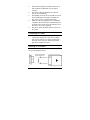
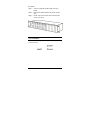
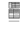
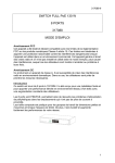
100BASE-FX to
100BASE-FX
Media Converter
User’s Guide
Rev. 01 (JUN. 2002)
1907M120SC26000
wan
RECYCLABLE
TABLE OF C ONTENTS
TABLE OF CONTENTS ...... 2
INTRODUCTION ................. 3
ABOUT MEDIA CONVERTER ......................... 3
PRODUCT FEATURES ................................... 3
INSTALLATION .................. 3
SELECTING A SITE FOR THE EQUIPMENT ....... 3
CONNECTING TO POWER ............................. 4
INSTALLING IN A CHASSIS ............................ 4
LED INDICATOR ........................................... 5
SPECIFICATIONS ................. 6
RECYCLABLE
Rev. 01 (Jan. 2002)
6012-9600133
1907M120SC16001
Printed In Taiwan
2
I NTRODUCTION
Thank you for choosing the 100Base Fast Ethernet
Media Converter, The Converter introduced here
provides one channel media conversion between
100BASE-FX and 100BASE-FX.
About Media Converter
Media Converter is a network technology specified by
IEEE 802.3u 100BASE-FX standards.
Product Features
y
y
y
y
y
y
One-channel media conversion between
100BASE-FX and 100BASE-FX
Fiber media allows: multi-mode fiber and
single-mode fiber using SC connector
Full wire-speed forwarding rate
Front panel status LEDs
Used as a stand-alone device or with a chassis
Hot-swappable when used with a chassis
I NSTALLATION
This chapter gives step-by-step installation instructions
for the Converter.
Selecting a Site for the Equipment
As with any electric device, you should place the
equipment where it will not be subjected to extreme
temperatures, humidity, or electromagnetic interference.
Specifically, the site you select should meet the
following requirements:
3
1.
2.
3.
4.
5.
The ambient temperature should be between 32
and 104 degrees Fahrenheit (0 to 40 degrees
Celsius).
The relative humidity should be less than 90
percent, non-condensing.
Surrounding electrical devices should not exceed
the electromagnetic field (RFC) standards for
IEC 801-3, Level 2 (3V/M) field strength.
Make sure that the equipment receives adequate
ventilation. Do not block the ventilation holes on
each side of the switch or the fan exhaust port on
the side or rear of the equipment.
The power outlet should be within 1.8 meters of
the switch.
Connecting to Power
1.
2.
This Converter is a plug-and-play device.
Connect the supplied AC to DC power adaptor
with a power voltage of 7.5Vdc/1.5Amp to the
DC-Jack on the converter, and then attach the
plug into a standard AC outlet.
Installing in a Chassis
The Converter can be fit into any of the expansion slots
on a special designed chassis.
y First, install the converter onto a carrier supplied with
4
the chassis:
Step 1- Unscrew and pull out the media converter
board.
Step 2- Plug in the media board to any of the vacant
slot.
Step 3- Fit the converter onto the carrier and use the
screw to secure it.
LED Indicator
The LED indicators give you instant feedback on status
of the converter:
5
LEDs
State
Indication
Power
Steady
Power on
(PWR)
Lights off
Power off
Lights on
Linking on port
FX-1
LINK-1
LINK-2
Lights off
Not Linking
Lights on
Linking on port
FX-2
Lights off
Not Linking
S PECIFICATIONS
Standards:
IEEE802.3u 100BASE-FX
Data Transfer Rate:
148800pps for 100Mbps
Duplex Mode:
Full Duplex Mode
LED indicators:
PWR, LINK-1, LINK-2
Media Interface:
SC
EMI Compatiblity:
FCC Class B
CE Certification, Class B
VCCI Class B
Temperture:
Storage: -10°C ~ 70°C
Operating: 0°C ~ 40°C
Humidity:
10% ~90% non-condensing
Power Consumption:
0.6 Watts (maximum)
6