1
Gearmotors \ Industrial Gear Units \ Drive Electronics \ Drive Automation \ Services
Explosion-Proof AC Motors,
Asynchronous Servomotors
Edition 04/2007
11559411 / EN
Operating Instructions
SEW-EURODRIVE – Driving the world
Contents
Contents
1
2
3
4
5
6
General Information ............................................................................................ 5
1.1
Structure of the safety notes ....................................................................... 5
1.2
Rights to claim under limited warranty ........................................................ 6
1.3
Exclusion of liability..................................................................................... 6
Safety Notes ........................................................................................................ 7
2.1
Preliminary information ............................................................................... 7
2.2
General ....................................................................................................... 7
2.3
Designated use ........................................................................................... 8
2.4
Other applicable documentation ................................................................. 8
2.5
Transportation ............................................................................................. 9
2.6
Installation / assembly................................................................................. 9
2.7
Inspection / maintenance ............................................................................ 9
Motor Design ..................................................................................................... 10
3.1
AC motor................................................................................................... 10
3.2
Nameplate, unit designation ..................................................................... 11
Mechanical Installation..................................................................................... 14
4.1
Before you start......................................................................................... 14
4.2
Mechanical installation .............................................................................. 14
Electrical Installation ........................................................................................ 17
5.1
General information .................................................................................. 17
5.2
Wiring notes .............................................................................................. 18
5.3
Special aspects for operation with a frequency inverter ........................... 18
5.4
Improving the grounding (EMC) ................................................................ 19
5.5
Environmental conditions during operation ............................................... 20
5.6
Motors and brakemotors in category 2G, 2D and 2 GD............................ 21
5.7
Motors and brake motors of category 3G, 3D and 3GD .......................... 26
5.8
Category 3D asynchronous servomotors.................................................. 34
Operating Modes and Limit Values ................................................................. 38
6.1
Permitted operating modes ....................................................................... 38
6.2
Frequency inverter operation in category 2G............................................ 38
6.3
Frequency inverter operation in categories 3G, 3D and 3GD ................... 45
6.4
Motor / inverter assignment: MOVIDRIVE® and MOVITRAC® ................. 48
6.5
Asynchronous motors: Thermal limit characteristic curves ....................... 49
6.6
Asynchronous servomotors: Limits for current and torque ....................... 50
6.7
Asynchronous servomotors: Thermal limit characteristic curves .............. 52
6.8
Asynchronous servomotors: Frequency inverter assignment ................... 53
6.9
Soft-start units ........................................................................................... 57
Operating Instructions – Explosion-Proof AC Motors, Asynchronous Servomotors
3
Contents
7
8
9
10
Startup................................................................................................................ 58
7.1
Prerequisites for startup ............................................................................ 58
7.2
Parameter setting: Frequency inverters for category 2G .......................... 59
7.3
Parameter setting: Frequency inverter for categories 3G, 3D, 3GD ......... 61
7.4
Altering the blocking direction on motors with a backstop ........................ 62
7.5
Anti-condensation heating for motors in category II3D ............................. 63
Inspection / Maintenance ................................................................................. 64
8.1
Inspection and maintenance periods ........................................................ 65
8.2
Preliminary work for motor and brake maintenance ................................. 65
8.3
Inspection / maintenance on the motor..................................................... 69
8.4
Inspection and maintenance of the brake BC ......................................... 72
8.5
Inspection and maintenance of BMG, BM ................................................ 82
Malfunctions ...................................................................................................... 88
9.1
Motor problems ......................................................................................... 88
9.2
Brake problems......................................................................................... 89
9.3
Malfunctions when operating with a frequency inverter ............................ 89
9.4
Customer service ...................................................................................... 89
Technical Data................................................................................................... 90
10.1 Work done, working air gap, braking torques of BMG05-8, BR03, BC .... 90
10.2 Work done, working air gap, braking torques of BM15 - 62 ...................... 91
10.3 Permitted work done by the brake ............................................................ 92
10.4 Operating currents .................................................................................... 95
10.5 Maximum permitted overhung loads ......................................................... 98
10.6 Permitted ball bearing types ................................................................... 100
11
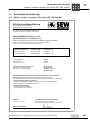
Declaration of Conformity .............................................................................. 101
11.1 Motors / brakes in category 2G, series eDT, eDV and BC ..................... 101
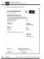
11.2 Motors in category 3GD, series eDT / eDV............................................. 102
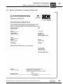
11.3 Motors / brakemotors in category 2GD and 2G ...................................... 103
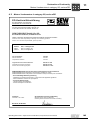
11.4 Motors / brakemotors in category 3D, series CT / CV ............................ 104
11.5 Motors / brakemotors in category 2G, series eDR .................................. 105
11.6 Motors / brakemotors in category 2D, series eDT / eDV ........................ 106
12
Appendix.......................................................................................................... 107
12.1 Operating and maintenance instructions for
WISTRO forced cooling fan .................................................................... 107
13
Address List .................................................................................................... 111
Index ................................................................................................................. 120
4
Operating Instructions – Explosion-Proof AC Motors, Asynchronous Servomotors
General Information
Structure of the safety notes
1
General Information
1.1
Structure of the safety notes
1
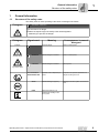
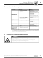
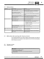
The safety notes in these operating instructions are designed as follows:
Pictogram
SIGNAL WORD!
Type and source of danger.
Possible consequence(s) if the safety notes are disregarded.
• Measure(s) to prevent the danger.
Pictogram
Example:
General danger
Signal word
Meaning
Consequences in case of
disregard
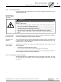
DANGER!
Imminent danger
Severe or fatal injuries
WARNING!
Possible dangerous situation
Severe or fatal injuries
CAUTION!
Possible dangerous situation
Minor injuries
Important note on explosion protection
Suspension of explosion protection and
dangers resulting from this
STOP!
Possible damage to property
Damage to the drive system or its environment
NOTE
Useful information or a tip
Simplifies the handling of the
drive system
Specific danger,
e.g. electric shock
NOTE ON EXPLOSION PROTECTION
Operating Instructions – Explosion-Proof AC Motors, Asynchronous Servomotors
5
General Information
Rights to claim under limited warranty
1
1.2
Rights to claim under limited warranty
A requirement of fault-free operation and fulfillment of any rights to claim under limited
warranty is that you adhere to the information in the operating instructions. Consequently, read the operating instructions before you start working with the unit!
Make sure that the operating instructions are available to persons responsible for the
plant and its operation, as well as to person who work independently on the unit. You
must also ensure that the documentation is legible.
1.3
Exclusion of liability
You must comply with the information contained in these operating instructions to ensure safe operation of the explosion-proof electric motors and to achieve the specified
product characteristics and performance requirements. SEW-EURODRIVE assumes no
liability for injury to persons or damage to equipment or property resulting from non-observance of these operating instructions. In such cases, any liability for defects is excluded.
6
Operating Instructions – Explosion-Proof AC Motors, Asynchronous Servomotors
Safety Notes
Preliminary information
2
Safety Notes
2.1
Preliminary information
2
The following basic safety notes must be read carefully to prevent injury to persons and
damage to property. The operator must make sure that the basic safety notes are read
and observed. Make sure that persons responsible for the plant and its operation, as
well as persons who work independently on the unit, have read through the operating
instructions carefully and understood them. If you are unclear about any of the information in this documentation, please contact SEW-EURODRIVE.
2.2
General
Never install damaged products or take them into operation. Submit a complaint to the
shipping company immediately in the event of damage.
During operation,motors and gearmotors can have live, bare and movable or rotating
parts as well as hot surfaces, depending on their enclosure.
Explosive gas mixtures or dust concentrations in combination with hot, energized and
moving parts of electrical machinery can cause serious injury or death.
Removing covers without authorization, improper use as well as incorrect installation or
operation may result in severe injuries to persons or damage to machinery.
Consult the documentation for additional information.
Operating Instructions – Explosion-Proof AC Motors, Asynchronous Servomotors
7
Safety Notes
Designated use
2
2.3
Designated use
The electric motors are intended for industrial systems. They fulfill the applicable standards and regulations:
•
Low Voltage Directive 73/23/EEC
•
Guideline 94/9/EC
•
pr EN 61241-0 Electrical apparatus for use in atmospheres containing combustible
dust: General requirements
•
EN 61241-1 Electrical apparatus for use in atmospheres containing combustible
dust: Protection through housing "tD"
•
EN 50281-1-1 Electrical apparatus for use in atmospheres containing combustible
dust: Protection through housing
•
EN 50281-1-2 Electrical apparatus for use in atmospheres containing combustible
dust: Protection through housing
•
EN 60079-0/EN 50014 Electrical apparatus for potentially explosive atmospheres:
General requirements
•
EN 60079-1/EN 50018 Electrical apparatus for potentially explosive atmospheres:
Flameproof enclosure "d"
•
EN 60079-7/EN 500019 Electrical apparatus for potentially explosive atmospheres:
Increased safety "e"
•
EN 60034 Rotating electrical machines
Technical data and information on the permitted conditions are given on the nameplate
and in the documentation; they have to be observed under all circumstances.
2.4
Other applicable documentation
The following publications and documents have to be observed as well:
8
•
"Explosion-Proof Gear Units R..7, F..7, K..7, S..7 Series, Spiroplan® W" operating
instructions for gearmotors
•
Operating instructions of the frequency inverter for motors powered by inverters
•
Operating instructions of installed options, if applicable
•
Corresponding wiring diagrams
Operating Instructions – Explosion-Proof AC Motors, Asynchronous Servomotors
Safety Notes
Transportation
2.5
2
Transportation
Inspect the shipment for any damage that may have occurred in transit as soon as you
receive the delivery. Inform the shipping company immediately. It may be necessary to
preclude startup.
Tighten installed eyebolts. They are only rated for the weight of the motor/gearmotor; do
not attach any additional loads.
The built-in lifting eyebolts meet DIN 580. Always observe the loads and regulations
listed in this standard. If the gearmotor is equipped with two suspension eye lugs or lifting eyebolts, then both of the suspension eye lugs should be used for transportation. In
this case, the tension force vector of the slings must not exceed a 45° angle in accordance with DIN 580.
Use suitable, sufficiently rated handling equipment if necessary. Remove any transportation fixtures prior to startup.
2.6
Installation / assembly
Follow the instructions in Sec. "Mechanical Installation"!
2.7
Inspection / maintenance
Follow the instructions in Sec. "Inspection / Maintenance"!
Operating Instructions – Explosion-Proof AC Motors, Asynchronous Servomotors
9
Motor Design
AC motor
3
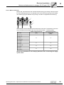
3
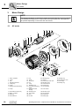
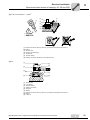
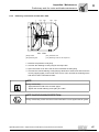
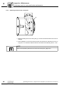
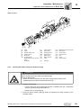
Motor Design
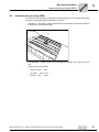
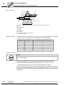
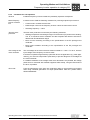
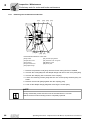
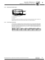
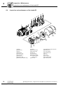
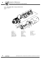
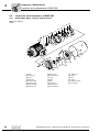
NOTE
The following illustration is intended to explain the general structure. Its only purpose
is to facilitate the assignment of components to the spare parts lists. Discrepancies
are possible depending on the motor size and version!
3.1
AC motor
31
44 41
20
1
3
12
11
10
9
7
106
2
13
107
100
101
103
22
35
32
36
37
42
116
118
117
119
111
16
112
123
135
130
129
1
2
3
7
9
10
11
10
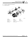
Rotor, complete
Circlip
Key
Flanged end shield
Screw plug
Circlip
Deep groove ball bearing
31
32
35
36
37
41
42
12 Circlip
44
13
16
20
22
100
101
103
106
Hex head screw (tie rod)
Stator, complete
Nilosring
Hex head bolt
Key
Circlip
Fan guard
Fan
V-ring
Equalizing ring
Non drive-end bearing
shield
Deep groove ball
bearing
Hexagonal nut
Lock washer
Stud
Oil seal
107
111
112
113
115
116
117
134
115
113
131
132
Oil-flinger ring
Gasket
Terminal box lower part
Machine screw
Terminal board
Terminal clip
Hex head bolt
131
132
134
135
Sealing ring
Terminal box cover
Screw plug
Sealing ring
118 Lock washer
119
123
129
130
Machine screw
Hex head bolt
Screw plug
Sealing ring
Operating Instructions – Explosion-Proof AC Motors, Asynchronous Servomotors
Motor Design
Nameplate, unit designation
3.2
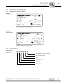
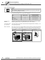
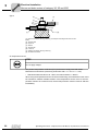
Nameplate, unit designation
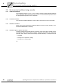
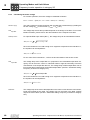
3.2.1
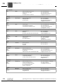
Nameplate of category 2 motors
3
Example:
Category 2G
Bruchsal / Germany
Typ
Nr.
1/min
kW
V
IM
eDT71D4
3009818304.0002.99
3
1465
0.37
230/400
B5
Nm
cos
tE s 29
Baujahr
Schmierstoff
0102
:1
i
A 1.97/1.14
IP 54
kg 9.2
IA / IN 3.7
0.70
Hz 50
Kl. B
II 2 G EEx e II T3
PTB 99 ATEX 3402/03
1999
186 228. 6.12
Figure 1: Nameplate for category 2G
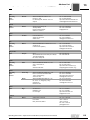
Example:
Category 2GD
76646 Bruchsal
Germany
Typ
Nr.
1/min
kW
V
Ta °C
eDT71D4
3009818304.0002.06
1465
0,37
230/400
-20 ... +40
Kl. F
tE s
29
0102
EN 60034
i
A
kg
3
:1
Nm
0,70
cos
1,97/1,14
Hz 50
9,2
IP 65 IM B5
II2G Ex e IIT3
Baujahr
IA/IN
3,7
2006
II2D Ex tD A21 IP65 T120°C
PTB 99 ATEX 3402/03
186 228 6.15
Figure 2: Nameplate for category 2GD
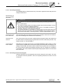
3.2.2
Unit designation
Example: AC
(brake) motor in
category 2G
eDT 71D 4 / BC05 / HR / TF
Temperature sensor (PTC resistor)
Manual brake release
Brake
Motor pole count
Motor size
Motor series
Operating Instructions – Explosion-Proof AC Motors, Asynchronous Servomotors
11
Motor Design
Nameplate, unit designation
3
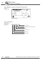
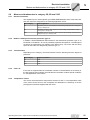
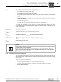
3.2.3
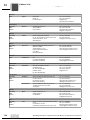
Nameplate of category 3 motors: Motor series DR, DT, DV
Example:
Category 3GD
76646 Bruchsal
Germany
DTF90S4/BMG/TF/II3G
Typ
3009818304.0001.06
Nr.
kW 1,1
cos
1/min 1300
V 230/400
A
-20... +40
Ta
°C kg
Bremse V 230
Nm
II3G Ex nA IIT3
EN 60034
3
:1
i
0,77
Nm
IM B5
4,85/2,8
Hz 50
31
Kl. F
IP 65
20
BMS1,5
Gleichrichter
II3D Ex tD A22 IP65 T140°C
Jahr 2006
Made in Germany
186 353 3.17
Figure 3: Nameplate
3.2.4
Unit designation
Example: AC
(brake) motor in
category 3G
DFT 90S 4 / BMG / TF / II3G
Unit category
Temperature sensor (PTC resistor)
Brake
Motor pole count
Motor size
Motor series
12
Operating Instructions – Explosion-Proof AC Motors, Asynchronous Servomotors
Motor Design
Nameplate, unit designation
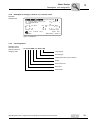
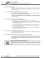
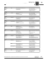
3.2.5
3
Nameplate of category 3 motors: CT, CV motor series
Example:
Category 3D
Bruchsal / Germany
Typ CV 100 L4 / BMG / TF / ES1S / II3D
Nr. 1783048036.0003.02
1/min 2100
Nm 66 max. Motor
1/min 3500
V
305
A 14.8
Ta
-20... +40
kg 40
Bremse V 400
Nm 40
II 3D
Ex tD A22 T 140° C
Schmierstoff
3
IEC 34
:1
i
Nm
max. Motor IM B3
Hz 73
IP 54
Kl. F
Gleichrichter BGE
Baujahr 2002
Made in Germany
187 835 2.13
Figure 4: Nameplate
3.2.6
Unit designation
Example: Asynchronous servo
(brake) motors in
category II3D
CV 100L4 / BMG / TF / ES1S / II3D
Unit category
Encoder type
Temperature sensor (PTC resistor)
Brake
Motor pole count
Motor size
Motor series
Operating Instructions – Explosion-Proof AC Motors, Asynchronous Servomotors
13
Mechanical Installation
Before you start
4
4
Mechanical Installation
NOTE
Observe the safety notes in section 2 during installation.
4.1
Before you start
The drive may only be installed when
•
the entries on the nameplate of the drive match the voltage supply system.
•
the drive is undamaged (no damage caused by transportation or storage).
•
it is certain that the conditions for the operational environment are complied with (see
Sec. "Safety Notes").
4.2
Mechanical installation
4.2.1
Preliminary work
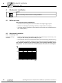
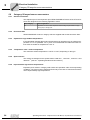
Long-term storage
of motors
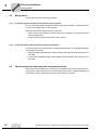
•
Please note that the grease utilization period of the ball bearings is reduced by 10 %
each year after storage periods exceeding one year.
•
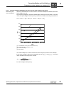
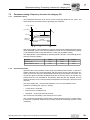
Check whether the motor has absorbed moisture as a result of being stored for a long
time. Measure the insulation resistance for this purpose (measuring voltage 500 V).
The insulation resistance (see following figure) varies greatly depending on the
temperature. The motor must be dried if the insulation resistance is not adequate.
[M ]
100
10
1
0,1
14
0
20
40
60
80
[˚C ]
Operating Instructions – Explosion-Proof AC Motors, Asynchronous Servomotors
Mechanical Installation
Mechanical installation
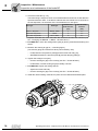
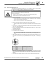
Drying the motor
4
Heat the motor:
•
with hot air or
•
via isolation transformer
– Connect the windings in series (see following figure)
– Auxiliary AC voltage supply max. 10 % of the rated voltage with max. 20 % of the
rated current
Trafo
The drying process is finished when the minimum insulation resistance has been exceeded.
Check terminal box whether:
•
the inside is clean and dry
•
the connections and fixing parts are free from corrosion
•
the joint seals are OK
•
the cable glands are sound, otherwise clean or replace them
Operating Instructions – Explosion-Proof AC Motors, Asynchronous Servomotors
15
Mechanical Installation
Mechanical installation
4
4.2.2
4.2.3
Installation tolerances
Shaft end
Flanges
Diameter tolerance in accordance with DIN 748
• ISO k6 for ∅ ≤ 50 mm
• ISO m6 for ∅ ≥ 50 mm
• Center bore in accordance with DIN 332, shape
DR..
Centering shoulder tolerance to DIN 42948
• ISO j6 for ∅ ≤ 230 mm
• ISO h6 for ∅ ≥ 230 mm
Installing the motor
•
The motor or gearmotor may only be mounted or installed in the specified mounting
position on a level and torsionally rigid support structure that is not subject to shocks.
•
Clean the output shafts thoroughly to ensure they are free of anti-corrosion agents
(use a commercially available solvent). Do not allow the solvent to penetrate the
bearings and shaft seals – this could damage the material.
•
Carefully align the motor and the driven machine to avoid placing any unacceptable
strain on the motor shafts (observe permitted overhung load and axial load!).
•
Do not butt or hammer the shaft end.
•
Ensure there is sufficient clearance around the unit to allow for adequate cooling.
Furthermore, the unit must be positioned in such a way that it does not reuse the air
warmed by other devices.
•
Balance components for subsequent mounting on the shaft with a half key (output
shafts are balanced with a half key).
NOTE ON EXPLOSION PROTECTION
•
•
Installation in
damp locations or
in the open
16
If using belt pulleys:
– Only use belts that do not build up an electrostatic charge.
– Do not exceed the maximum permitted overhung load; for motors without gear
units, see Sec. "Maximum permitted overhung loads" (page 96) (page 98).
Use an appropriate cover to protect motors in vertical mounting positions from
objects or fluids entering (protection cowl C)!
•
Use suitable cable glands for the incoming cable (use reducing adapters if
necessary) according to the installation instructions.
•
Coat the threads of cable glands and screw plugs with sealant and tighten them well
– then coat them again.
•
Seal the cable entry well.
•
Clean the sealing surfaces of the terminal box and the terminal box cover carefully
before re-assembly; gaskets have to be glued in on one side. Replace brittle gaskets.
•
Restore the anticorrosion coating if necessary
•
Check enclosure according to nameplate
Operating Instructions – Explosion-Proof AC Motors, Asynchronous Servomotors
Electrical Installation
General information
5
5
Electrical Installation
NOTE
•
•
Observe the safety notes in section 2 during installation.
Switch contacts in utilization category AC-3 to EN 60947-4-1 must be used for
switching the motor and the brake.
5.1
General information
5.1.1
Additional regulations for potentially explosive atmospheres
In addition to the generally applicable installation regulations for low-voltage electrical
equipment (e.g. in Germany: DIN VDE 0100, DIN VDE 0105), it is also necessary to
comply with the special provisions on setting up electrical machinery in potentially explosive atmospheres (operating safety regulations in Germany: EN 60079-14; EN
50281-1-2; EN 61241-14 and specific provisions for the machine).
5.1.2
Using the wiring diagrams
Connect the motor only as shown in the wiring diagram included with the motor. Do not
connect or start up the motor if this wiring diagram is missing. You can obtain the valid
wiring diagram free of charge from SEW-EURODRIVE.
5.1.3
Cable entries
The terminal boxes have metric threaded holes according to EN 50262 or NPT threaded
holes according to ANSI B1.20.1-1983. All metric cable entries are supplied with ATEX
certified closing plugs.
To establish the correct cable entry, the sealing plugs must be replaced by ATEX approved cable glands with strain relief. Select the cable screw fitting according to the
outer diameter of the cable used. The IP enclosure of the cable entry must be at least
as high as the IP enclosure of the motor.
All cable entries that are not required must be sealed off with an ATEX certified closing
plug after completion of the installation (→ maintaining the enclosure).
5.1.4
Equipotential bonding
In accordance with EN 60079-14, IEC 61241-14 and EN 50281-1-1, a connection may
have to be established to an equipotential bonding system. Note Sec. "Improving the
grounding (EMC)" (page 19).
Operating Instructions – Explosion-Proof AC Motors, Asynchronous Servomotors
17
Electrical Installation
Wiring notes
5
5.2
Wiring notes
Comply with the safety notes during startup.
5.2.1
Protection against interference from brake control systems
Do not route brake cables alongside switched-mode power cables, as otherwise there
is a risk of disrupting brake control systems.
Switched-mode power cables include in particular:
5.2.2
•
Output cables from frequency inverters and servo controllers, converters, soft start
units and brake units
•
Supply cables for brake resistors and similar options
Protecting motor protection devices against interference
To protect SEW motor protection devices (temperature sensors TF, winding thermostats
TH) against interference:
5.3
•
Route separately shielded supply cables together with switched-mode power lines in
one cable.
•
Do not route unshielded supply cables together with switched-mode power lines in
one cable.
Special aspects for operation with a frequency inverter
When motors are powered from inverters, you must adhere to the wiring instructions issued by the inverter manufacturer. It is essential to observe Sec. "Operating Modes and
Limit Values" and the operating instructions of the frequency inverter.
18
Operating Instructions – Explosion-Proof AC Motors, Asynchronous Servomotors
Electrical Installation
Improving the grounding (EMC)
5.4
5
Improving the grounding (EMC)
For improved, low-impedance grounding at high frequencies, we recommend using the
following connections with the DR/DV/DT AC motors:
•
Size DT71 ... DV 132S: [1] M5x10 thread rolling screw and 2 serrated lock washers
to DIN 6798 in the stator housing.
[1]
•
Size DV112M... DV280: Screw and 2 serrated lock washers in the bore of the eye
bolt.
Thread size of the eye bolt:
– DV112 / 132S:
M8
– DV132M ... 180L: M12
– DV200 ... 280:
M16
Operating Instructions – Explosion-Proof AC Motors, Asynchronous Servomotors
19
Electrical Installation
Environmental conditions during operation
5
5.5
Environmental conditions during operation
5.5.1
Ambient temperature
The temperature range of -20 °C to 40 °C must be ensured unless specified otherwise
on the nameplate. Motors intended for use in higher or lower ambient temperatures have
the appropriate designation on the nameplate.
5.5.2
Installation altitude
The maximum installation altitude of 1000 m above sea level must not be exceeded.
5.5.3
Hazardous radiation
Motors must not be subjected to hazardous radiation (such as ionizing radiation). Contact SEW-EURODRIVE if necessary.
5.5.4
Hazardous gases, vapors and dusts
If used according to their designated use, explosion-proof motors are incapable of igniting explosive gases, vapors or dusts. However, explosion-proof motors may not be subjected to gases, vapors or dusts that endanger operational safety, for example through
•
Corrosion
•
Damage to the protective coating
•
Damage to the sealing agent
etc.
20
Operating Instructions – Explosion-Proof AC Motors, Asynchronous Servomotors
Electrical Installation
Motors and brakemotors in category 2G, 2D and 2 GD
5.6
Motors and brakemotors in category 2G, 2D and 2 GD
5.6.1
General information
5
The explosion-proof / dust explosion-proof SEW-EURODRIVE motors of the eDR, eDT
and eDV series are designed for the following application zones.
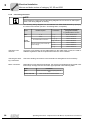
5.6.2
Motor category
Area of application
2G
Application in zone 1 and compliance with the design requirements for equipment
group II, category 2G.
2D
Application in zone 21 and compliance with the design requirements for equipment group II, category 2D.
2GD
Application in zone 1 or zone 21 and compliance with the design requirements for
equipment group II, category 2GD.
Brakes in flameproof enclosure protection type "d"
In addition, SEW-EURODRIVE offers brakes in the determinant protection type "d" to
EN 50018 or EN 60079-1 for use in potentially explosive atmospheres. The flameproof
enclosure for brakemotors only applies to the brake cavity. The motor and the wiring
space for the brake are designed in protection type "e".
5.6.3
Terminal boxes
Depending on the category, the terminal boxes have the following minimum degree of
protection.
5.6.4
Motor category
Degree of protection
2G
IP54
2D
IP65
2GD
IP65
Code "X"
If the code "X" appears after the certification number on the declaration of conformity or
the EC prototype test certificate, this indicates the certificate contains special conditions
for safe application of the motors.
5.6.5
Temperature classes
The motors are authorized for temperature classes T3 and T4. The temperature class
of the motor can be found on the nameplate, the declaration of conformity or the EC
prototype test certificate supplied with the motor.
Operating Instructions – Explosion-Proof AC Motors, Asynchronous Servomotors
21
Electrical Installation
Motors and brakemotors in category 2G, 2D and 2 GD
5
5.6.6
Surface temperatures
The maximum surface temperature is 120°C. Information about the surface temperature
of the motor can be found on the nameplate, the declaration of conformity or the EC prototype test certificate
5.6.7
Protection against impermissibly high surface temperatures
The increased safety protection type requires that the motor is switched off before it
reaches the maximum permitted surface temperature.
The motor can be protected with a motor protection switch or a positive temperature
coefficient (PTC) thermistor. The type of motor protection is specified in the EC prototype test certificate.
5.6.8
Protection exclusively with motor protection switch
Note the following when installing the motor protection switch to EN 60947:
5.6.9
•
For categories 2G and 2GD: With starting current ratio IA/IN listed on the
nameplate, the response time of the motor protection switch must be less than the
warm-up time tE of the motor.
•
The motor protection switch must trip immediately in the event of a phase failure.
•
The motor protection switch must be approved by a notified body and assigned a
corresponding inspection number.
•
The motor protection switch must be set to the rated motor current indicated on the
nameplate or in the prototype test certificate.
Protection exclusively with PTC thermistor (TF)
The positive coefficient thermistor must be evaluated using a suitable device. Observe
the applicable installation regulations.
5.6.10 Protection with motor protection switch and additional PTC thermistor
The conditions stated for exclusive protection with motor protection switches also apply
here. Protection with positive temperature coefficient thermistors (TF) only represents a
supplementary protection measure which is irrelevant to certification for potentially explosive conditions.
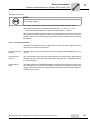
NOTE ON EXPLOSION PROTECTION
Proof of the efficacy of the installed protective equipment is required prior to startup.
22
Operating Instructions – Explosion-Proof AC Motors, Asynchronous Servomotors
Electrical Installation
Motors and brakemotors in category 2G, 2D and 2 GD
5
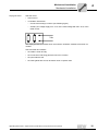
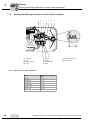
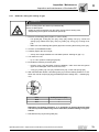
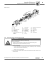
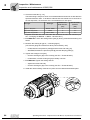
5.6.11 Motor connection
Motors with a terminal block with a slotted terminal stud [1] according to directive 94/9/
EC (see following figure) are only allowed to be connected using lugs [3] to DIN 46295.
The cable lugs [3] are attached using forcing nuts with an integrated lock washer [2].
1
2
3
Alternatively, a solid round wire can be used for the connection. The diameter of the wire
must correspond to the width of the slot in the terminal stud (→ following table).
Motor size
Widths of terminal stud slot
[mm]
Tightening torque of the
forcing nut
[Nm]
2.5
4.0
3.1
4.0
4.3
6.0
6.3
10.0
eDT 71 C, D
eDT 80 K, N
eDT 90 S, L
eDT 100 LS, L
eDV 100 M, L
eDV 112 M
eDV 132 S
eDV 132 M, ML
eDV 160 M
eDV 160 L
eDV 180 M, L
Observe the permitted air and creeping distances when connecting the supply
system cable.
Operating Instructions – Explosion-Proof AC Motors, Asynchronous Servomotors
23
Electrical Installation
Motors and brakemotors in category 2G, 2D and 2 GD
5
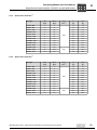
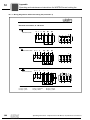
5.6.12 Connecting the motor
NOTE
It is essential to comply with the valid wiring diagram! Do not connect or start up the
motor if this wiring diagram is missing.
The following wiring diagrams can be obtained from SEW-EURODRIVE by specifying
the motor order number ( Sec. "Type code, nameplate"):
Series
Number of poles
Associated wiring diagram
(designation/number)
X = placeholder for version
eDR 63
4, 6
DT14 / 08 857 X 03
eDT and eDV
4, 6
DT13 / 08 798 X 06
4
AT101 / 09 861 X 04
eDT with brake BC
Checking cross
sections
Check the cross sections of the cables based on the rated motor current, the valid installation regulations and the requirements where the unit is installed.
Checking the winding connections
Check the winding connections in the terminal box and tighten them if necessary (→ observe tightening torques).
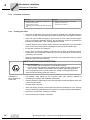
Motor connection
With motors of size 63, the supply cables must be secured in the spring clamp terminal
strip according to the wiring diagram. Connect the protective earth to the protective conductor connection so that the cable lug and housing material are separated by a washer.
connection
TF TF
24
4
connection
3
2
1
TF TF
4
PE connection
3
2
1
Operating Instructions – Explosion-Proof AC Motors, Asynchronous Servomotors
Electrical Installation
Motors and brakemotors in category 2G, 2D and 2 GD
5
TF temperature sensor
STOP
Do not apply voltage!
The positive temperature coefficient (PTC) thermistors comply with DIN 44082.
Resistance measurement (measuring instrument with V ≤ 2.5 V or I < 1 mA):
•
Standard measured values: 20...500 Ω, thermal resistance > 4000 Ω
When using the temperature sensor for thermal monitoring, the evaluation function must
be activated to maintain reliable isolation of the temperature sensor circuit. If the temperature reaches an excessive level, the thermal protection function must be effective
immediately.
5.6.13 Connecting the brake
The flameproof brake BC (Ex de) is released electrically. The brake is applied mechanically when the voltage is switched off.
Inspecting the ignition gap
Check the ignition gap of the flameproof brake for damage before establishing the connection
Checking cross
sections
The cross sections of the connection cables between the rectifier and the brake must be
sufficiently large to guarantee the function of the brake (see Sec. "Operating currents"
in "Technical Data").
Connecting the
brake
The brake rectifier from SEW-EURODRIVE is installed and connected in the switch cabinet according to the enclosed circuit diagram, outside the potentially explosive atmosphere. Connect the connection cables between the rectifier and the separate brake terminal box on the motor.
Operating Instructions – Explosion-Proof AC Motors, Asynchronous Servomotors
25
Electrical Installation
Motors and brake motors of category 3G, 3D and 3GD
5
5.7
Motors and brake motors of category 3G, 3D and 3GD
5.7.1
General information
The explosion-proof / dust explosion-proof SEW-EURODRIVE motors of the DR 63, DT,
DTE, DV and DVE series are designed for the following application zones.
5.7.2
Motor category
Area of application
3G
Application in zone 2 and compliance with the design requirements for equipment
group II, category 3G.
3D
Application in zone 22 and compliance with the design requirements for equipment group II, category 3D.
3GD
Application in zone 2 or 22 and compliance with the design requirements for
equipment group II, category 3GD.
Enclosure IP54
SEW-EURODRIVE motors in category 3G, 3D and 3GD are supplied with at least enclosure IP54.
5.7.3
Operation at high ambient temperatures
If the nameplate indicates that motors are allowed to be operated up to an ambient temperature of > 50 °C (standard: 40 °C), then it is essential that the cables and cable
glands used are suited for temperatures ≥ 90 °C.
5.7.4
Temperature class / surface temperature
The motors are designed for temperature class T3. The maximum surface temperature
is 120°C or 140°C.
5.7.5
Protection against impermissibly high surface temperatures
Explosion-proof motors in category 3G, 3D and 3GD ensure safe operation under normal operating conditions. The motor must be switched off securely in the case of overload to avoid the risk of impermissibly high surface temperatures.
The motor can be protected with a motor protection switch or a positive temperature coefficient (PTC) thermistor. For permitted operating modes depending on the motor protection, see Sec. "Permitted operating modes" (page 38) . SEW-EURODRIVE equips
brake motors and pole-changing motors in category 3G, 3D and 3GD with positive coefficient thermistors (TF).
26
Operating Instructions – Explosion-Proof AC Motors, Asynchronous Servomotors
Electrical Installation
Motors and brake motors of category 3G, 3D and 3GD
5.7.6
5
Protection exclusively with motor protection switch
Note the following when installing the motor protection switch to EN 60947:
5.7.7
•
The motor protection switch must trip immediately in the event of a phase failure.
•
The motor protection switch must be set to the rated motor current indicated on the
nameplate.
•
Pole-changing motors must be protected with mutually interlocked motor protection
switches for each pole number.
Protection exclusively with PTC thermistor (TF)
The positive coefficient thermistor must be evaluated using a suitable device. Observe
the applicable installation regulations.
5.7.8
Protection with motor protection switch and additional PTC thermistor
The conditions stated for exclusive protection with motor protection switches also apply
here. Protection with positive temperature coefficient thermistors (TF) only represents a
supplementary protection measure which is irrelevant to certification for potentially explosive conditions.
NOTE ON EXPLOSION PROTECTION
Proof of the efficacy of the installed protective equipment is required prior to startup.
Operating Instructions – Explosion-Proof AC Motors, Asynchronous Servomotors
27
Electrical Installation
Motors and brake motors of category 3G, 3D and 3GD
5
5.7.9
Connecting the motor
NOTE
It is essential to comply with the valid wiring diagram! Do not connect or start up the
motor if this wiring diagram is missing.
The following wiring diagrams can be obtained from SEW-EURODRIVE by specifying
the motor order number (see Sec. "Unit designation, nameplate"):
Series
DR63
DT, DV,
DTE, DVE
Number of poles
/
4, 6, 8
/
/
8/4 in Dahlander connection
/
/
All pole-changing motors with sep /
arate windings
/
4, 6
Associated wiring diagram
(designation/number)
X = placeholder for version
DT14 / 08 857 X 03
DT13 / 08 798 X 6
DT33 / 08 799 X 6
DT53 / 08 739 X 1
DT43 / 08 828 X 7
DT45 / 08 829 X 7
DT48 / 08 767 X 3
Checking cross
sections
Check the cross sections of the cables based on the rated motor current, the valid installation regulations and the requirements where the unit is installed.
Checking the winding connections
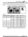
Check the winding connections in the terminal box and tighten them if necessary.
Motor connection
Depending on size and electrical design, the motors are supplied and connected in different ways. Comply with the connection type specified in the following table.
Series
Connection
DR63
Motor connection via tension spring terminal
strip
DT, DV, DTE, DVE
28
Connection
Motor connection via terminal board
Operating Instructions – Explosion-Proof AC Motors, Asynchronous Servomotors
Electrical Installation
Motors and brake motors of category 3G, 3D and 3GD
Motor connection
tension spring terminal strip
5
With motors of size 63, the supply cables must be secured in the spring clamp terminal
strip according to the wiring diagram. Connect the protective earth to the protective conductor connection so that the cable lug and housing material are separated by a washer.
connection
TF TF
4
connection
3
2
TF TF
1
4
PE connection
3
2
1
Motor connection
terminal board
Terminal stud
diameter
Tightening torque of
the hex nut
Connection at
customer site
Design
Connection
type
Scope of delivery
≤ 1.5 mm2
Type 1a
Massive wire
Conductor end
sleeve
Pre-assembled terminal
links
≤ 6 mm2
Type 1b
Ring cable lug
Pre-assembled terminal
links
≤ 6 mm2
Type 2
Ring cable lug
Small connection accessories in enclosed bag
Cross section
M4
1.6 Nm
M5
2.0 Nm
≤ 10 mm2
Type 2
Ring cable lug
Small connection accessories in enclosed bag
M6
3.0 Nm
≤ 16 mm2
Type 3
Ring cable lug
Small connection accessories in enclosed bag
M8
6.0 Nm
≤ 25 mm2
Type 3
Ring cable lug
Connection accessories preassembled
M10
10.0 Nm
≤ 50 mm2
Type 3
Ring cable lug
Connection accessories preassembled
M12
15.5 Nm
2 x ≤ 50 mm2
Type 3
Ring cable lug
Connection accessories preassembled
M16
30.0 Nm
2 x ≤ 95 mm2
Type 3
Ring cable lug
Connection accessories preassembled
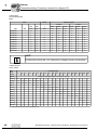
The types printed in bold apply to S1 operation for the standard voltages and standard
frequencies according to the data specified in the catalog. Alternative versions can have
different connections, e.g. other diameters of the terminal studs, and/or a different scope
of delivery.
Operating Instructions – Explosion-Proof AC Motors, Asynchronous Servomotors
29
Electrical Installation
Motors and brake motors of category 3G, 3D and 3GD
5
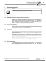
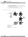
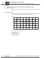
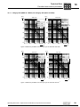
Type 1
a)
If the cross section of the external connection is ≤ 1.5 mm2, it can be installed
directly below the terminal washer.
b)
If the cross section of the external connection is > 1.5 mm2, it must be installed
with a cable lug below the terminal washer.
Observe the permitted air and creeping distances for the connection.
Type 1a: Cross section ≤ 1.5 mm2
[2]
[1]
≥ 8 - < 10 mm
[1]
[3]
[4]
[5]
[6]
≤ 1.5 mm2
> AWG 16
> 1.5 mm2
[1]
[2]
[3]
[4]
[5]
[6]
30
External connection with cross section ≤ 1.5 mm2
Terminal stud
Hexagon nut with flange
Terminal link
Terminal washer
Winding connection with Stocko connection terminal
Operating Instructions – Explosion-Proof AC Motors, Asynchronous Servomotors
Electrical Installation
Motors and brake motors of category 3G, 3D and 3GD
5
Type 1b: Cross section > 1.5 mm2
[2]
[1]
[1]
[3]
[4]
[5]
[6]
> 1.5 mm2
≤ AWG 16
[1] External connection with ring cable lug, for example according to DIN 46237 or
DIN 46234
[2] Terminal stud
[3] Hexagon nut with flange
[4] Terminal link
[5] Terminal washer
[6] Winding connection with Stocko connection terminal
Type 2
[1]
[2]
[5]
[6]
[3]
[7]
[4]
[8]
[1] Terminal stud
[2] Lock washer
[3] Terminal washer
[4] Winding connection
[5] Upper nut
[6] Washer
[7] External connection with ring cable lug, for example according to DIN 46237 or
DIN 46234
[8] Lower nut
Operating Instructions – Explosion-Proof AC Motors, Asynchronous Servomotors
31
Electrical Installation
Motors and brake motors of category 3G, 3D and 3GD
5
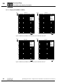
Type 3
[2]
[1]
[3]
[4]
[5]
[6]
[8]
[7]
[1] External connection with ring cable lug, for example according to DIN 4637 or DIN
46234
[2] Terminal stud
[3] Upper nut
[4] Washer
[5] Terminal link
[6] Lower nut
[7] Winding connection with ring cable lug
[8] Serrated lock washer
TF temperature sensor
STOP
Do not apply voltage!
The positive temperature coefficient (PTC) thermistors comply with DIN 44082.
Resistance measurement (measuring instrument with V ≤ 2.5 V or I < 1 mA):
•
Standard measured values: 20...500 Ω, thermal resistance > 4000 Ω
When using the temperature sensor for thermal monitoring, the evaluation function must
be activated to maintain reliable isolation of the temperature sensor circuit. If the temperature reaches an excessive level, the thermal protection function must be effective
immediately.
32
Operating Instructions – Explosion-Proof AC Motors, Asynchronous Servomotors
Electrical Installation
Motors and brake motors of category 3G, 3D and 3GD
5
5.7.10 Connecting the brake
The BMG/BM brake is released electrically. The brake is applied mechanically when the
voltage is switched off.
Note the limit values for permitted
work done
DANGER!
Risk of explosion if the maximum permitted braking work per braking operation is
exceeded.
Severe or fatal injuries.
• The maximum braking work per braking operation must not be exceeded, not even
in the case of emergency braking operations.
• The limit values of the permitted braking work (see sec. "Permitted work done by
the brake" (page 92) ) must always be observed.
• The machine designer is responsible for ensuring that the machine dimensions are
selected correctly on the basis of the SEW-EURODRIVE project planning regulations and the brake data in "Drive Engineering - Practical Implementation, Vol. 4".
Checking the function of the brake
Check that the brake is functioning correctly prior to startup to make sure the brake linings are not rubbing,as this would lead to overheating.
Checking cross
sections
The cross sections of the connection cables between the power system, the rectifier and
the brake must be sufficiently large to guarantee the function of the brake (see Sec. "Operating currents" in "Technical Data").
Connecting the
brake rectifier
Depending on its design and function, the SEW-EURODRIVE brake rectifier or brake
control system is installed and connected according to the enclosed circuit diagram. For
category 3G and 3GD, the brake rectifier or brake control system has to be installed in
the control cabinet outside the potentially explosive area. For category 3D, installation
is permitted in the control cabinet outside the potentially explosive area or in the terminal
box of the motor.
5.7.11 Connecting VE forced cooling fan
Category II3D motors can be equipped with a forced cooling fan as an option. For notes
on connection and safe operation, refer to the operating instructions of the VE forced
cooling fan.
Operating Instructions – Explosion-Proof AC Motors, Asynchronous Servomotors
33
Electrical Installation
Category 3D asynchronous servomotors
5
5.8
Category 3D asynchronous servomotors
5.8.1
General information
The explosion-proof / dust explosion-proof SEW-EURODRIVE motors of the CT and CV
series are designed for the following application zones.
5.8.2
Motor category
Area of application
3D
Application in zone 22 and compliance with the design requirements for equipment group II, category 3D.
Enclosure IP54
SEW-EURODRIVE motors in category II3D are supplied with at least enclosure IP54.
5.8.3
Operation at high ambient temperatures
If the nameplate indicates that motors are allowed to be operated up to an ambient temperature of > 50 °C (standard: 40 °C), then it is essential that the cables and cable entries used are suited for temperatures ≥ 90 °C.
5.8.4
Temperature class / surface temperature
The maximum surface temperature is 120°C or 140°C, depending on the type.
5.8.5
Speed classes
The motors are designed in the speed classes 1200 min-1, 1700 min-1, 2100 min-1 and
3000 min-1 (see sec. "Operating Modes and Limit Values")
5.8.6
Impermissible high surface temperatures
Explosion-proof motors in category II3D ensure safe operation under normal operating
conditions. The motor must be switched off securely in the case of overload to avoid the
risk of impermissibly high temperatures.
34
Operating Instructions – Explosion-Proof AC Motors, Asynchronous Servomotors
Electrical Installation
Category 3D asynchronous servomotors
5.8.7
5
Protection against excessive temperature
To ensure that the permitted limit temperature is not exceeded, explosion-proof asynchronous servomotors in the CT and CV series are always equipped with a positive temperature coefficient thermistor (TF). When installing the positive temperature coefficient,
it is important that the sensor is evaluated by a device approved for this purpose so it
complies with the 94/9/EC directive. The positive coefficient thermistor must be evaluated using a suitable device. Observe the applicable installation regulations.
5.8.8
Connecting the motor
NOTE
It is essential to comply with the valid wiring diagram! Do not connect or start up the
motor if this wiring diagram is missing.
The following wiring diagrams can be obtained from SEW-EURODRIVE by specifying
the motor order number (see Sec. "Unit designation, nameplate"):
Series
Number of poles
Connection
Associated wiring diagram
(designation/number)
X = placeholder for version
CT, CV
4
/
DT13 / 08 798 X 6
Checking cross
sections
Check the cross sections of the cables based on the rated motor current, the valid installation regulations and the requirements where the unit is installed.
Checking the winding connections
Check the winding connections in the terminal box and tighten them if necessary.
Operating Instructions – Explosion-Proof AC Motors, Asynchronous Servomotors
35
5
Electrical Installation
Category 3D asynchronous servomotors
Motor connection
[2]
[1]
[3]
[4]
[5]
[6]
[8]
[7]
[1] External connection with ring cable lug, for example according to DIN 4637 or DIN
46234
[2] Terminal stud
[3] Upper nut
[4] Washer
[5] Terminal link
[6] Lower nut
[7] Winding connection with ring cable lug
[8] Serrated lock washer
Tightening torques
Arrange the cables and terminal links as shown in the wiring diagram and screw them
on firmly. Observe the tightening torques specified in the following table.
Diameter of the terminal studs
Tightening torque of the hex nut [Nm]
M4
1.6
M5
2
M6
3
M8
6
M10
10
M12
15.5
M16
30
TF temperature sensor
STOP
Do not apply voltage!
The positive temperature coefficient (PTC) thermistors comply with DIN 44082.
Resistance measurement (measuring instrument with V ≤ 2.5 V or I < 1 mA):
•
Standard measured values: 20...500 Ω, thermal resistance > 4000 Ω
When using the temperature sensor for thermal monitoring, the evaluation function must
be activated to maintain reliable isolation of the temperature sensor circuit. If the temperature reaches an excessive level, the thermal protection function must be effective
immediately.
36
Operating Instructions – Explosion-Proof AC Motors, Asynchronous Servomotors
Electrical Installation
Category 3D asynchronous servomotors
5.8.9
5
Connecting the brake
The BMG/BM brake is released electrically. The brake is applied mechanically when the
voltage is switched off.
Note the limit values for permitted
work done
DANGER!
Risk of explosion if the maximum permitted braking work per braking operation is
exceeded.
Severe or fatal injuries.
• The maximum braking work per braking operation must not be exceeded, not even
in the case of emergency braking operations.
• The limit values of the permitted braking work (see sec. "Permitted work done by
the brake" (page 92) ) must always be observed.
• The machine designer is responsible for ensuring that the machine dimensions are
selected correctly on the basis of the SEW-EURODRIVE project planning
regulations and the brake data in "Drive Engineering - Practical Implementation,
Vol. 4".
Checking the function of the brake
Check that the brake is functioning correctly prior to startup to make sure the brake linings are not rubbing,as this would lead to overheating.
Checking cross
sections
The cross sections of the connection cables between the power system, the rectifier and
the brake must be sufficiently large to guarantee the function of the brake (see Sec. "Operating currents" in "Technical Data").
Connecting the
brake rectifier
Depending on its design and function, the SEW-EURODRIVE brake rectifier or brake
control system is
•
connected in the terminal box of the motor
•
or in the switch cabinet outside the potentially explosive atmosphere.
. In either case, connect the connect cables between the voltage supply, rectifier and
brake connections according to the wiring diagram.
5.8.10 Connecting VE forced cooling fan
Category II3D motors can be equipped with a forced cooling fan as an option. For notes
on connection and safe operation, refer to the operating instructions of the VE forced
cooling fan.
Operating Instructions – Explosion-Proof AC Motors, Asynchronous Servomotors
37
kVA
6
i
f
n
Operating Modes and Limit Values
Permitted operating modes
P Hz
6
Operating Modes and Limit Values
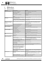
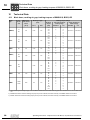
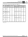
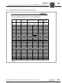
6.1
Permitted operating modes
Motor type and
unit category
Protection against
impermissibly high temperatures exclusively by
eDT../eDV..
II2G
Protective circuit breaker
eDT..BC..
II2G
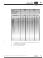
Permitted operating mode
•
•
S1
Heavy starting not possible1)
•
•
S1
S4 / no-load starting frequency according to
catalog data / starting frequency is to be
calculated under load
Frequency inverter operation according to
specifications
Heavy start1)
PTC thermistor (TF)
•
•
eDT../eDV..
II2D
Motor protection switch and positive coefficient temperature thermistor (TF)
DR/DT/DV
II3GD/II3D
Protective circuit breaker
DR/DT/DV
DT..BM../DV..BM..
II3GD/II3D
PTC thermistor (TF)
•
•
•
S1
No heavy start
Frequency inverter operation according to
specifications
•
•
S1
No heavy start1)
•
•
S1
S4 / no-load starting frequency according to
catalog data / starting frequency is to be
calculated under load
Heavy start
Frequency inverter operation according to
specifications
Soft-start units
•
•
•
1) Heavy starting is present when a motor protection switch that was properly selected and set for normal
operating conditions trips during the acceleration time. This is usually the case when the acceleration time is >
1.7 x tE time.
6.2
Frequency inverter operation in category 2G
6.2.1
Using category 2G motors
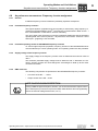
NOTES ON EXPLOSION PROTECTION
The following applies
• The frequency inverter can only be operated with motors that are permitted for this
operating mode according to the EC prototype test certificate.
• It is not permitted to connect more than one of the described motors to one
frequency inverter.
• The voltage at the motor terminal board must projected be to prevent overheating.
• For startup, ensure that the motor voltage complies with the specifications of the
EC prototype test certificate.
• If the motor voltage is too low (undercompensation), slip increases, which causes
higher temperatures in the rotor of the motor.
• If the motor voltage is too high (overcompensation), the stator current is very high
and the winding temperature rises more sharply.
• If the mechanical load is the same, operation on a frequency inverter causes a
more significant motor temperature rise due to the harmonic content in current and
voltage.
38
Operating Instructions – Explosion-Proof AC Motors, Asynchronous Servomotors
Operating Modes and Limit Values
Frequency inverter operation in category 2G
6.2.2
kVA
i
f
n
6
P Hz
Conditions for safe operation
General
Install the frequency inverter outside the potentially explosive atmosphere.
Motor/frequency
inverter combination
Inverters have to fulfill the following conditions for powering explosion-proof motors:
Thermal motor
protection
Overvoltage at the
motor terminals
•
Control mode: constant machine flow
•
Rated output current of the frequency inverter ≤ twice the rated motor current
•
Switching frequency > 3 kHz
Thermal motor protection is ensured by the following measures:
•
Winding temperature monitoring through PTC thermistors (TF) built into the winding.
The TF is monitored via an evaluation unit that complies with directive 94/9 and is
labeled with Ex identification II(2)G.
•
Motor current monitoring according to the specifications of the EC prototype test
certificate.
•
Motor torque limitation according to the specifications of the EC prototype test
certificate.
The overvoltage at the motor terminals must be limited to < 1700 V. To do so, limit the
input voltage at the frequency inverter to 500V.
If the drive is operated regeneratively quite often due to the application (e.g. hoist applications), you must use output filters (sine filters) to prevent dangerous overvoltages at
the motor terminals.
If a reliable calculation of the voltage at the motor terminals is not possible, the voltage
peaks have to measured with suitable equipment after startup, using the rated load of
the drive, if possible.
Gear units
From the perspective of the gear unit, restrictions apply to the maximum input speed
when using controlled gearmotors. For input speeds above 1500 min-1 please contact
SEW-EURODRIVE.
Operating Instructions – Explosion-Proof AC Motors, Asynchronous Servomotors
39
6
kVA
i
6.2.3
f
n
Operating Modes and Limit Values
Frequency inverter operation in category 2G
P Hz
Calculating the motor voltage
For inverter operation, the motor voltage is calculated as follows:
Umotor = Umains − ( ΔUinp.filter / choke + ΔUFI + ΔUoutp.filter + ΔUcable )
UPower supply
The mains voltage is measured directly with a multimeter or alternatively by reading the
DC link voltage (UVZ) in the inverter ( Umains = UVZ/1,35 ).
Δ Uinput filter
The voltage drop across the input filter depends on the design of the filter. For more detailed information, please refer to the documentation of the respective line filter.
Δ Uinput choke
For optional SEW input chokes (ND...), the voltage drop can be calculated as follows.
ΔUinp.choke = I × 3 × (2 × π × f × L )2 + R 2
Since the resistance R is small enough to be neglected compared to the inductance L,
the equation can be simplified to:
ΔUinp.choke = I × 3 × 2 × π × f × L
For the value of the inductance L, refer to the documentation of the the line choke.
Δ Uoutput filter
The voltage drop at the output filter is in proportion to the modulated output basic frequency and to the motor current. In individual cases it might be necessary to ask the
manufacturer of the output filter about it. The voltage drop of SEW output filters can be
found in the table "Voltage drop across SEW output filters" (see Sec. "Parameter setting:
Frequency inverters for category 2G").
ΔUoutp.filter = I × 3 × (2 × π × f × L )2 + R 2
Since the resistance R is small enough to be neglected compared to the inductance L,
the equation can be simplified to:
ΔUoutp.filter = I × 3 × 2 × π × f × L
Δ UCable
40
The voltage drop of the motor cable depends on the motor current and the cross section,
length and material of the cable. The voltage drop can be found in the table "Voltage
drop at the motor cable" (see Sec. "Parameter setting: Frequency inverters for category
2G").
Operating Instructions – Explosion-Proof AC Motors, Asynchronous Servomotors
Operating Modes and Limit Values
Frequency inverter operation in category 2G
UFI
kVA
i
f
n
6
P Hz
The voltage drop at the inverter is determined by:
•
the voltages across the rectifier path
•
the voltages at the output stage transistors
•
the transformation principle from mains to DC link voltage and then to three-phase
voltage
•
the anti-overlap times resulting from the clocking of the output stage and the missing
voltage-time areas
•
the modulation process
•
the load state and the energy dissipation of the DC link capacitors
To simplify the calculation, use the value of 7.5% of the supply input voltage. This value
is to be taken as the maximum possible voltage drop at the inverter. This ensures a reliable configuration.
fbreak, motor
Breakpoint of the motor
fbreak, FI
Breakpoint frequency, set at the frequency inverter
Ubreak, FI
Voltage at breakpoint fbreak, FI, set at the frequency inverter
Σ Udeviation
∑ Udeviation = (UFI + ΔUoutp.filter + ΔUcable + ΔUinp.filter / choke )
UBreak
Rated voltage of the motor
NOTE
The voltage drop across the output filter has to be compensated by the slope of the V/
f characteristic curve (breakpoint).
The voltage drop at the cable is compensated by the IxR compensation. SEW frequency inverters adjust this value in the "Automatic calibration ON" mode every time
the frequency inverter is started.
6.2.4
Determining the motor breakpoint
To avoid undercompensation, the motor breakpoint has to be projected so that the voltage drop (see Sec. "Determining the voltage drop") between mains and motor is taken
into account.
There are 3 ways to ensure this:
•
Terminal voltage at breakpoint < Rated voltage of the motor
•
Terminal voltage at breakpoint can be set to the rated voltage of the motor.
•
Motor voltage selection
Operating Instructions – Explosion-Proof AC Motors, Asynchronous Servomotors
41
6
kVA
i
6.2.5
f
n
Operating Modes and Limit Values
Frequency inverter operation in category 2G
P Hz
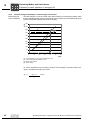
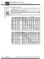
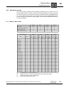
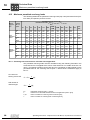
Terminal voltage at breakpoint < Rated voltage of the motor
The base frequency is set to a lower value at the frequency inverter during startup. Note
that the available speed range is now limited. In this example, the field weakening range
(undercompensation) begins below 50 Hz already.
U [V]
Determining the
motor breakpoint
500
450
[4]
400
350
[3]
300
250
[2]
200
[1]
150
100
50
0
0
10
20
30
40
50
60
f [Hz]
[1]
[2]
[3]
[4]
V/f characteristic curve (motor characteristic curve)
V/f corrected (set characteristic curve)
Rated motor voltage
Mains voltage
To set the breakpoint at the frequency inverter in this example, set 400V and the frequency calculated according to formula
ftype, FI =
ftype, motor
× Umains
Utype + ∑ Udeviation
.
42
Operating Instructions – Explosion-Proof AC Motors, Asynchronous Servomotors
Operating Modes and Limit Values
Frequency inverter operation in category 2G
6.2.6
kVA
i
f
n
6
P Hz
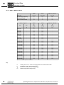
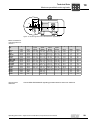
Terminal voltage at breakpoint can be set to the rated voltage of the motor.
Determining the
motor breakpoint
On the V/f characteristic curve of the motor, the motor breakpoint is raised by the calculated voltage drop ΔU.
For this kind of projecting, the entire speed range of the motor can be used. As a crosscheck, the input voltage of the frequency inverter has to fulfill the following requirements:
Umains ≥ Umotor + (UFI + ΔUoutp.filter + ΔUcable + ΔUinp.filter / choke )
600
[4]
500
400
U [V]
[3]
300
[2]
200
[1]
100
0
0
10
20
30
40
50
60
f [Hz]
[1]
[2]
[3]
[4]
V/f characteristic curve (motor characteristic curve)
V/f corrected (set characteristic curve)
Rated motor voltage
Mains voltage
To set the breakpoint, set 464 V and 50 Hz at the frequency inverter in this example.
If the mains voltage is below the calculated value of (Ubreak + ΔUdeviation ), enter the
value calculated according to the formula
ftype, FI =
ftype, motor
× Umains
Utype + ∑ Udeviation
for mains voltage and frequency.
Operating Instructions – Explosion-Proof AC Motors, Asynchronous Servomotors
43
6
kVA
i
6.2.7
f
n
Operating Modes and Limit Values
Frequency inverter operation in category 2G
P Hz
Motor voltage selection
Determining the
motor breakpoint
Select a motor (winding) with a rated voltage that corresponds exactly to the calculated
voltage at the motor terminal board. Note that the modified motor winding requires a proportionally higher current.
ftype, FI =
ftype, motor
× Umains
Utype + ∑ Udeviation
The following values are set at the inverter:
ftype, FI = ftype, motor
Utype, FI = Utype + ∑ Udeviation
NOTES
The maximum frequency may not exceed the value of fbreak, motor .
44
Operating Instructions – Explosion-Proof AC Motors, Asynchronous Servomotors
Operating Modes and Limit Values
Frequency inverter operation in categories 3G, 3D and 3GD
6.3
Frequency inverter operation in categories 3G, 3D and 3GD
6.3.1
Using motors in category II3GD
kVA
i
f
n
6
P Hz
NOTE ON EXPLOSION PROTECTION
The following applies
• Use as category II3G unit in zone 2:
The same conditions and restrictions apply as to category II3D motors.
• Use as category II3D unit in zone 22:
The same conditions and restrictions apply as to category II3G motors
• Use as category II3GD unit in both zone 2 and zone 22:
In this case, the more stringent conditions and restrictions apply (see details on
II3G and II3D).
6.3.2
Conditions for safe operation
General
Install the frequency inverter outside the potentially explosive atmosphere.
Motor/frequency
inverter combination
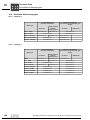
•
The listed motor/frequency inverter combinations are recommended for category
II3G motors. Frequency inverters that have similar values with respect to output
current and output voltage (EN60079-15) can also be used.
•
The listed motor/frequency inverter combinations are recommended for category
II3D motors. If you want to operate category II3D motors on other frequency
inverters, the maximum speeds/frequencies and the thermal torque limiting
characteristic curves must also be observed. In addition, we strongly recommend
you use a frequency inverter matching the respective power rating.
•
Motors in category II3G are in the temperature class T3.
•
The maximum surface temperature of II3D motors is 120°C or 140°C.
•
II3GD motors are in temperature class T3 and have a maximum surface temperature
of 120°C or 140°C.
Temperature class
and maximum surface temperature
Operating Instructions – Explosion-Proof AC Motors, Asynchronous Servomotors
45
6
kVA
i
f
n
Operating Modes and Limit Values
Frequency inverter operation in categories 3G, 3D and 3GD
P Hz
Protection against
excessive temperature
Only motors that are equipped with a positive temperature coefficient thermistor (TF) are
permitted for operation on a frequency inverter to ensure that the permitted limit temperature is not exceeded. The positive temperature coefficient thermistor has to be evaluated using an appropriate device.
Supply voltage of
the frequency
inverter
The supply voltage of the frequency inverter must not fall below the value of 400 V.
Overvoltage at the
motor terminals
The overvoltage at the motor terminals must be limited to < 1700 V. To do so, limit the
input voltage at the frequency inverter to 500V.
If the drive is operated regeneratively quite often due to the application (e.g. hoist applications), you must use output filters (sine filters) to prevent dangerous overvoltages at
the motor terminals.
If a reliable calculation of the voltage at the motor terminals is not possible, the voltage
peaks have to measured with suitable equipment after startup, using the rated load of
the drive, if possible.
EMC measures
The following components are permitted for the MOVIDRIVE® frequency inverters:
•
Line filters of the NF...-... series
•
Output chokes of the HD... series
•
Output filter (sine filter) HF..
If an output filter is used, the voltage drop has to be compensated via the filter. Observe Sec. "Calculating the motor voltage" (page 40).
NOTE ON EXPLOSION PROTECTION
If using a different type of frequency inverter, you must ensure that the output connection of the frequency inverter to improve the EMC characteristics does not significantly
reduce the terminal voltage at the motor (≤ 5 %).
46
Operating Instructions – Explosion-Proof AC Motors, Asynchronous Servomotors
Operating Modes and Limit Values
Frequency inverter operation in categories 3G, 3D and 3GD
kVA
i
f
n
6
P Hz
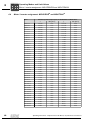
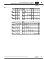
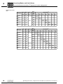
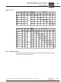
Maximum permitted torques
Motors operated with a frequency inverter must not exceed the maximum torques specified in this section. The values may be exceeded for brief periods if the effective operating point lies below the characteristic curve.
Maximum permitted speeds/frequencies
It is essential to observe the maximum speeds frequencies listed in the assignment tables for the motor/frequency inverter combinations. These values must not be exceeded.
Group drives
Group drive means that several motors are connected to one frequency inverter output.
NOTE ON EXPLOSION PROTECTION
Motors of the DR/DT/DV/DTE/DVE series in category II3G or II3GD for use in zone 2
may generally not be operated as group drive!
The following restrictions apply to motors of the DR/DT/DV/DTE/DVE series in category
II3D for use in zone 22:
Gear units
•
The line lengths specified by the frequency inverter manufacturer must not be
exceeded.
•
The motors in a group must not be more than two power ratings apart.
•
Each motor has to be monitored.
From the perspective of the gear unit, restrictions apply to the maximum speed when
using controlled gearmotors. For input speeds above 1500 min-1 please contact SEWEURODRIVE.
Operating Instructions – Explosion-Proof AC Motors, Asynchronous Servomotors
47
6
kVA
i
6.4
f
n
Operating Modes and Limit Values
Motor / inverter assignment: MOVIDRIVE® and MOVITRAC®
P Hz
Motor / inverter assignment: MOVIDRIVE® and MOVITRAC®
Motor
Maximum permitted output power of MOVIDRIVE® and MOVITRAC®
nMax [min-1]
DR 63 S 4
0.25 kW
2100
0.25 kW
3600
DR 63 M 4
0.25 kW
2100
0.37 kW
3600
DR 63 L 4
0.25 kW
2100
0.55 kW
3600
DT 71 K 4
0.25 kW
2100
0.25 kW
3600
DT 71 C 4
0.25 kW
2100
0.37 kW
3600
DT 71 D 4
0.37 kW
2100
0.55 kW
3600
DT 80 K 4
0.55 kW
2100
0.75 kW
3600
DT 80 N 4
0.75 kW
2100
1.1 kW
3600
DT 90 S 4
1.1 kW
2100
1.5 kW
3600
DT 90 L 4
1.5 kW
2100
2.2 kW
3600
DV 100 M 4
2.2 kW
2100
3.0 kW
3600
DV 100 L 4
3.0 kW
2100
4.0 kW
3600
DV 112 M 4
4.0 kW
2100
5.5 kW
3600
DV 132 S 4
5.5 kW
2100
7.5 kW
3600
DV 132 M 4
7.5 kW
2100
9.2 kW
3600
DV 132 ML4
9.2 kW
2100
11 kW
3600
DV 160 M 4
11 kW
2100
15 kW
3600
DV 160 L 4
15 kW
2100
22 kW
3600
DV 180 M 4
22 kW
2100
22 kW
2700
DV 180 L 4
22 kW
2100
37 kW
2700
DV 200 L 4
37 kW
2100
37 kW
2700
DV 225 S 4
37 kW
2100
55 kW
2700
DV 225 M 4
55 kW
2100
55 kW
2700
DVE 250 M 4
55 kW
2100
75 kW
2500
DVE 280 S 4
48
nMax [min-1]
75 kW
2100
132 kW
2500
DTE 90 K4
0.75 kW
2100
1.1 kW
3000
DTE 90 C4
0.75 kW
2100
1.1 kW
3000
DTE 90 S4
1.1 kW
2100
1.1 kW
3000
DTE 90 L4
1.5 kW
2100
2.2 kW
3000
DVE 100 M4
2.2 kW
2100
4.0 kW
3000
DVE 100 L4
3.0 kW
2100
5.5 kW
3000
DVE 112 M4
4.0 kW
1800
7.5 kW
2400
DVE 132 S4
5.5 kW
1800
11 kW
2000
DVE 132 M4
7.5 kW
1800
11 kW
2000
DVE 160 M4
11 kW
1800
22 kW
2000
DVE 160 L4
15 kW
1800
22 kW
2400
DVE 180 M4
22 kW
1800
37 kW
2400
DVE 180 L4
22 kW
1800
37 kW
2500
DVE 200 L4
37 kW
1800
55 kW
2500
DVE 225 S4
37 kW
1800
55 kW
2500
DVE 250 M4
55 kW
2100
90 kW
2500
DVE 280 S4
75 kW
2100
132 kW
2500
Operating Instructions – Explosion-Proof AC Motors, Asynchronous Servomotors
kVA
Operating Modes and Limit Values
Asynchronous motors: Thermal limit characteristic curves
6.5
Asynchronous motors: Thermal limit characteristic curves
6.5.1
Thermal torque limit characteristic curves
i
n
f
6
P Hz
Thermal torque limit characteristic curve in inverter operation for 4-pole AC motors and
AC brake motors in connection:
M/M rated
1.20
[3]
1.00
[1]
0.80
0.60
[2]
0.40
0.20
0.00
0
400
800
1200
1600
2000
2400
2800
3200
3600
n [1/min]
[1] 104 Hz limit characteristic curve
[2] 87 Hz limit characteristic curve
[3] with VE forced cooling fan
Thermal torque limit characteristic curve in inverter operation for 4-pole AC motors and
AC brake motors in connection:
M/M rated
1.20
1.00
[3]
[1]
0.80
0.60
[2]
0,40
0,20
0,00
0
200
400
600
800
1000
1200
1400
1600
1800
2000
n [1/min]
[1] 60 Hz limit characteristic curve
[2] 50 Hz limit characteristic curve
[3] with VE forced cooling fan
Operating Instructions – Explosion-Proof AC Motors, Asynchronous Servomotors
49
6
kVA
i
6.6
f
n
Operating Modes and Limit Values
Asynchronous servomotors: Limits for current and torque
P Hz
Asynchronous servomotors: Limits for current and torque
NOTE ON EXPLOSION PROTECTION
The values specified in the table for maximum current, torque and speed must not be
exceeded during operation.
6.6.1
Speed class 1200 min-1
Motor type
6.6.2
Mmax
nmax
IN
Imax
[Nm]
[min-1]
[A]
[A]
CT71D4.../II3D
2.1
6
1.1
2.7
CT80N4.../II3D
4.3
13
1.9
4.4
CT90L4.../II3D
8.5
26
3.3
8.2
CV100M4.../II3D
13
38
4.2
10.9
CV100L4.../II3D
22
66
CV132S4.../II3D
31
94
CV132M4.../II3D
43
CV132ML4.../II3D
52
CV160M4.../II3D
CV160L4.../II3D
7.5
20.4
10.1
26.9
128
10.7
26.9
156
16.0
43.2
62
186
19.8
52.7
81
242
26.7
69.6
CV180M4.../II3D
94
281
CV180L4.../II3D
106
319
CV200L4.../II3D
170
510
MN
Mmax
[Nm]
[Nm]
3500
32.3
79.2
35.3
88.7
51.0
137.5
nmax
IN
Imax
[min-1]
[A]
[A]
2500
Speed class 1700 min-1
Motor type
50
MN
[Nm]
CT71D4.../II3D
2.0
6
1.5
3.7
CT80N4.../II3D
4.3
13
2.6
6.1
CT90L4.../II3D
8.5
26
4.5
11.3
CV100M4/...II3D
13
38
5.8
14.9
CV100L4.../II3D
22
66
10.2
28.0
CV132S4.../II3D
31
94
13.9
37.1
CV132M4.../II3D
41
122
18.5
49.6
CV132ML4.../II3D
49
148
23.1
61.6
CV160M4.../II3D
60
181
26.8
70.7
CV160L4.../II3D
76
227
35.2
90.1
CV180M4.../II3D
89
268
CV180L4.../II3D
98
293
CV200L4..../II3D
162
485
3500
2500
43.3
104.5
50.2
123.0
68.9
183.9
Operating Instructions – Explosion-Proof AC Motors, Asynchronous Servomotors
Operating Modes and Limit Values
Asynchronous servomotors: Limits for current and torque
6.6.3
i
f
n
6
P Hz
Speed class 2100 min-1
Motor type
6.6.4
kVA
MN
Mmax
nmax
-1
[min ]
IN
Imax
[Nm]
[Nm]
[A]
[A]
CT71D4.../II3D
2.1
6
1.9
4.6
CT80N4.../II3D
4.3
13
3.3
7.6
CT90L4..../II3D
8.5
26
5.7
14.1
CV100M4.../II3D
13
38
7.3
18.8
CV100L4.../II3D
21
64
12.5
34.0
CV132S4.../II3D
31
94
17.4
46.6
CV132M4.../II3D
41
122
18.1
44.9
CV132ML4.../II3D
49
148
26.7
71.3
CV160M4.../II3D
60
179
33.3
87.6
CV160L4.../II3D
75
224
43.9
112.1
CV180M4.../II3D
85
255
52.8
125.6
3500
CV180L4.../II3D
98
293
CV200L4.../II3D
149
446
2500
MN
Mmax
nmax
-1
57.9
141.9
79.8
209.4
IN
Imax
Speed class 3000 min-1
Motor type
[Nm]
[Nm]
[A]
[A]
CT71D4.../II3D
2.0
6
2.6
6.1
CT80N4.../II3D
3.8
11
4.3
9.6
CT90L4.../II3D
8.1
24
7.5
18.6
CV100M4.../II3D
13
38
10.0
25.9
CV100L4.../II3D
18
54
15.0
39.5
CV132S4.../II3D
30
89
23.0
60.9
CV132M4.../II3D
38
115
30.4
80.8
CV132ML4.../II3D
44
133
36.9
96.1
CV160M4.../II3D
54
163
43.0
110.9
CV160L4.../II3D
72
217
59.1
149.3
CV180M4.../II3D
79
237
69.9
161.8
CV180L4.../II3D
94
281
CV200L4.../II3D
123
370
Operating Instructions – Explosion-Proof AC Motors, Asynchronous Servomotors
[min ]
3500
2500
84.6
204.4
98.5
246.0
51
6
kVA
i
f
n
Operating Modes and Limit Values
Asynchronous servomotors: Thermal limit characteristic curves
P Hz
6.7
Asynchronous servomotors: Thermal limit characteristic curves
6.7.1
Note the speed class
During project planning, note that the characteristic curves are different for each speed
class.
6.7.2
Operating mode
The characteristic curves show the permitted torque ratings in continuous duty S1. Determine the effective operating point for different operating modes.
M/Mnenn
1.2
[4]
[5]
1.0
[3]
0.8
[1]
0.6
[2]
0.4
0.2
0.0
0
500
1000
1500
2000
2500
3000
3500
4000
n
Figure 5: Thermal torque limit characteristic curves
[1]
[2]
[3]
[4]
[5]
52
Speed class 1200 1/min
Speed class 1700 1/min
Speed class 2100 1/min
Speed class 3000 1/min
with VE forced cooling fan
Operating Instructions – Explosion-Proof AC Motors, Asynchronous Servomotors
Operating Modes and Limit Values
Asynchronous servomotors: Frequency inverter assignment
6.8
Asynchronous servomotors: Frequency inverter assignment
6.8.1
General
kVA
i
f
n
6
P Hz
Install the frequency inverter outside the potentially explosive atmosphere.
6.8.2
Permitted frequency inverters
The highest dynamic properties and control quality is achieved by using frequency inverters from the MOVIDRIVE series®. The frequency inverters listed in table "CT/CV.../
II3D - MOVIDRIVE®" combinations" are then mandatory.
The use of other types of frequency inverters is permitted. Make sure that the permitted
operating data of the motors (see Sec. "Asynchronous servomotors: Limits for current
and torque" (page 50)) is not exceeded.
6.8.3
Permitted operating modes for MOVIDRIVE frequency inverters
To ensure highest dynamic properties, frequency inverters of the MOVIDRIVE® series
must be started up in a CFC operating mode. VFC operating modes are also permitted.
6.8.4
Supply voltage of the frequency inverter
The supply voltage of the frequency inverter must not fall below the minimum value of
400 V.
The maximum permitted supply voltage must be limited to 500 V. Otherwise, the frequency inverter currents can cause dangerous overvoltages to build up at the motor
connection terminals.
6.8.5
EMC measures
The following components are permitted for the MOVIDRIVE® frequency inverters:
•
Line filters of the NF...-... series
•
Output chokes of the HD... series
NOTE ON EXPLOSION PROTECTION
If using a different type of frequency inverter, you must ensure that the output connection of the frequency inverter to improve the EMC characteristics does not significantly
reduce the terminal voltage at the motor (≤ 5 %).
Operating Instructions – Explosion-Proof AC Motors, Asynchronous Servomotors
53
6
kVA
i
6.8.6
f
n
Operating Modes and Limit Values
Asynchronous servomotors: Frequency inverter assignment
P Hz
CT/CV.../II3D - MOVIDRIVE combinations
Recommended
combination
The table lists the recommended motor/MOVIDRIVE® combinations depending on the
speed class. Other combinations should not be used because this could cause an overload in the motors.
NOTE ON EXPLOSION PROTECTION
The values specified in the table for maximum current and maximum speed must not
be exceeded during operation!
Speed class 1200
min-1
Motor type
Mmax
nmax
[Nm]
[Nm]
[min-1]
CT71D4 /
II3D
2.1
6
CT80N4 /
II3D
4.3
13
8.5
26
13
38
CV100L4 /
II3D
22
66
CV132S4 /
II3D
31
94
CV132M4 /
II3D
43
128
MN
Mmax
nmax
[Nm]
[Nm]
[min-1]
CV132ML4 /
II3D
52
156
CV160M4 /
II3D
62
186
CV160L4 /
II3D
81
242
CV180M4 /
II3D
94
281
CV180L4 /
II3D
106
319
CV200L4 /
II3D
170
510
CT90L4
/II3D
CV100M4 /
II3D
Motor type
54
MN
3500
3500
2500
Mmax
nbase
[Nm]
[Hz]
Mmax
nbase
Mmax
nbase
Mmax
nbase
Mmax
nbase
Mmax
nbase
Mmax
nbase
Mmax
nbase
Mmax
nbase
[Nm]
[Hz]
Mmax
nbase
Mmax
nbase
Mmax
nbase
Mmax
nbase
Mmax
nbase
Mmax
nbase
MOVIDRIVE®
0015
7.5
600
13.0
540
18.2
928
0022
25.7
781
29.0
883
0030
0040
0055
37.0
781
32.6
1062
45.3
947
60
813
64
992
0075
0110
84
915
82
1011
125
877
MOVIDRIVE®
0110
0150
126
922
125
986
156
819
169
909
163
1043
0220
240
954
241
1050
231
1018
0300
0370
0450
0550
282
986
308
973
326
1011
402
986
494
947
510
940
0750
Operating Instructions – Explosion-Proof AC Motors, Asynchronous Servomotors
kVA
Operating Modes and Limit Values
Asynchronous servomotors: Frequency inverter assignment
Speed class 1700
min-1
Motor type
MN
Mmax
nmax
[Nm]
[Nm]
[min-1]
CT71D4 /
II3D
2.1
6
CT80N4 /
II3D
4.3
13
CT90L4 /
II3D
8.5
26
CV100M4 /
II3D
13
38
CV100L4 /
II3D
22
66
CV132S4 /
II3D
31
94
MN
Mmax
nmax
[Nm]
[Nm]
[min-1]
CV132M4 /
II3D
41
122
CV132ML4 /
II3D
49
148
CV160M4 /
II3D
60
181
CV160L4 /
II3D
76
227
CV180M4 /
II3D
89
268
CV180L4 /
II3D
98
293
CV200L4 /
II3D
162
485
Motor type
3500
3500
2500
Mmax
nbase
[Nm]
[Hz]
Mmax
nbase
Mmax
nbase
Mmax
nbase
Mmax
nbase
Mmax
nbase
Mmax
nbase
Mmax
nbase
[Nm]
[Hz]
Mmax
nbase
Mmax
nbase
Mmax
nbase
Mmax
nbase
Mmax
nbase
Mmax
nbase
Mmax
nbase
i
f
n
6
P Hz
MOVIDRIVE®
0015
0022
0030
18.0
1400
23.5
1280
25.7
1402
0040
0055
0075
0110
36.0
1274
32.9
1510
44.2
1402
57
1274
59
1470
91
1330
6.0
1250
12.6
1150
MOVIDRIVE®
0110
0150
89
1440
83
1562
121
1330
114
1485
120
1420
Operating Instructions – Explosion-Proof AC Motors, Asynchronous Servomotors
0220
148
1331
176
1310
170
1470
168
1550
0300
0370
226
1400
226
1510
217
1450
268
1460
269
1420
0450
0550
0750
353
1421
420
1395
485
1344
55
6
kVA
i
f
n
Operating Modes and Limit Values
Asynchronous servomotors: Frequency inverter assignment
P Hz
Speed class 2100
min-1
Motor type
Mmax
nmax
[Nm]
[Nm]
[min-1]
CT71D4 /
II3D
2.1
6
CT80N4 /
II3D
4.3
13
CT90L4 /
II3D
8.5
26
CV100M4 /
II3D
13
38
CV100L4 /
II3D
21
64
MN
Mmax
nmax
[Nm]
[Nm]
[min-1]
CV132S4 /
II3D
31
94
CV132M4 /
II3D
41
122
CV132ML4 /
II3D
49
148
CV160M4 /
II3D
60
179
CV160L4 /
II3D
75
225
CV180M4 /
II3D
85
255
CV180L4 /
II3D
98
293
CV200L4 /
II3D
149
447
Motor type
56
MN
3500
3500
2500
Mmax
nbase
[Nm]
[Hz]
Mmax
nbase
Mmax
nbase
Mmax
nbase
Mmax
nbase
Mmax
nbase
Mmax
nbase
[Nm]
[Hz]
Mmax
nbase
Mmax
nbase
Mmax
nbase
Mmax
nbase
Mmax
nbase
Mmax
nbase
Mmax
nbase
Mmax
nbase
MOVIDRIVE®
0015
0022
6.0
1280
9.7
1754
13.0
1510
0030
0040
18.3
1843
25.5
1677
28.0
1760
0055
0075
0110
38.0
1626
33.7
2003
44.0
1894
64
1645
MOVIDRIVE®
0110
0150
72
1850
94
1722
95
1850
0220
122
1670
139
1715
139
1792
0300
179
1690
177
1882
0370
218
1824
218
1939
0450
255
1894
260
1824
0550
0750
293
1786
329
1830
412
1792
Operating Instructions – Explosion-Proof AC Motors, Asynchronous Servomotors
kVA
Operating Modes and Limit Values
Soft-start units
Speed class 3000
min-1
Motor type
Mmax
nmax
[Nm]
[Nm]
[min-1]
CT71D4 /
II3D
2.0
6
CT80N4 /
II3D
3.8
11
CT90L4 /
II3D
8.1
24
CV100M4 /
II3D
13
38
CV100L4 /
II3D
18
54
MN
Mmax
nmax
[Nm]
[Nm]
[min-1]
CV132S4 /
II3D
30
89
CV132M4 /
II3D
38
115
CV132ML4 /
II3D
44
133
CV160M4 /
II3D
54
163
CV160L4 /
II3D
72
217
CV180M4 /
II3D
79
237
CV180L4 /
II3D
94
281
CV200L4 /
II3D
123
370
Motor type
6.9
MN
3500
3500
2500
Mmax
nbase
[Nm]
[Hz]
Mmax
nbase
Mmax
nbase
Mmax
nbase
Mmax
nbase
Mmax
nbase
Mmax
nbase
[Nm]
[Hz]
Mmax
nbase
Mmax
nbase
Mmax
nbase
Mmax
nbase
Mmax
nbase
Mmax
nbase
Mmax
nbase
Mmax
nbase
i
f
n
6
P Hz
MOVIDRIVE®
0015
0022
0030
0040
0055
9.7
2560
11.0
2350
12.7
2790
18.0
2650
24.0
2490
26.5
2620
0075
0110
34.6
2490
31.8
2800
49.0
2600
6.0
2280
MOVIDRIVE®
0110
0150
51
2740
69
2650
67
2750
0220
0300
99
2600
94
2765
98
2630
114
2450
124
2656
131
2550
124
2720
0370
133
2547
161
2470
155
2680
150
2790
0450
0550
0750
192
2620
191
2745
182
2620
216
2545
228
2700
220 276
2580 2540
293
2573
Soft-start units
Soft-start units are permitted for use with motors in category II3D as long as the motors
are fitted with a TF temperature sensor.
Operating Instructions – Explosion-Proof AC Motors, Asynchronous Servomotors
57
I
7
Startup
Prerequisites for startup
0
7
Startup
7.1
Prerequisites for startup
NOTES
Observe the safety notes in section 2 during installation.
7.1.1
Before startup, make sure that:
•
The drive is undamaged and not blocked.
•
the measures stipulated in section "General Preparations" are performed after
extended storage period,
•
All connections have been made properly
•
The direction of rotation of the motor/gearmotor is correct
– (motor rotating clockwise: U, V, W to L1, L2, L3)
7.1.2
•
All protective covers have been installed correctly.
•
All motor protection equipment is active and set for the rated motor current
•
The self-reengaging manual brake release is used in case of hoist drives
•
There are no other sources of danger present
During startup, make sure that:
•
The motor is running correctly (no overload, no speed fluctuation, no loud noises,
etc.).
•
The correct braking torque is set according to the specific application (see Sec.
"Technical Data")
•
in case of problems (see Sec. "Malfunctions")
STOP
In brake motors with self-reengaging manual brake release, the manual brake release
lever must be removed after startup/maintenance! A bracket is provided for storing the
lever on the outside of the motor.
58
Operating Instructions – Explosion-Proof AC Motors, Asynchronous Servomotors
Startup
Parameter setting: Frequency inverters for category 2G
I
7
0
7.2
Parameter setting: Frequency inverters for category 2G
7.2.1
Parameter setting
The parameters that have to be set for current monitoring depend on the motor. The
exact values are specified in the EC prototype test certificate.
Current limitation
I1
1.5 In (motor)
Io
In (motor)
Io
B
C
I2
A
Depends on
motor type
Permitted
continuous current range
fA
fB
fC
fbase
f/Hz
After motor startup, current limitation I1 is active. Current limit I2 determines the permanently permitted current. The current limitation function can be activated during startup
or via parameter P560 current limitation Ex e motor (for permitted motors).
The characteristic curve is defined by operating points A, B and C. The following parameters are set during startup:
Parameter
7.2.2
Point A
Point B
Point C
Frequency [Hz]
P561
P563
P565
Current limitation in % of IN
P562
P564
P566
Overload protection
Operation above the permitted current range is permitted for 60 seconds. To prevent a
sudden reduction of the current limitation and thus torque shocks, after about 50 seconds, the current is reduced to the permitted value along a ramp within 10 seconds. The
current can again exceed the permitted range after a recovery time of 10 minutes. Operation below 5 Hz is permitted for 60 seconds. After this time has elapsed, the unit
switches off with error F110 Ex e protection and performs an emergency stop as an error
response.
The binary inputs P62_ can be parameterized to "Ex e current limitation active".
Conditions for setting the output ("1" signal):
•
Current limit 1 exceeded
•
Recovery time not elapsed yet
•
Operation < 5 Hz longer than 60 seconds
The current-time monitoring is not reset by an error reset.
The current-time monitoring is active both for mains operation and 24 V backup mode.
If the mains is switched off without 24 V backup mode, the monitoring function is reset
completely.
Operating Instructions – Explosion-Proof AC Motors, Asynchronous Servomotors
59
I
7
Startup
Parameter setting: Frequency inverters for category 2G
0
Voltage drop
across SEW output
filters
Filter
Choke
Voltage drop [V]
V = 400 V
V = 500 V
IN400
IN500
L
50 Hz
60 Hz
87 Hz
50 Hz
60 Hz
87 Hz
Size
(A)
(A)
(mH)
(V)
(V)
(V)
(V)
(V)
(V)
HF 008-503
1
2,5
2
11
15
18
26
12
14
21
HF 015-503
1
4
3
9
20
24
34
15
18
26
HF 022-503
1
6
5
7
23
27
40
19
23
33
HF 030-503
1
8
6
5,5
24
29
42
18
22
31
HF 040-503
2
10
8
4,5
24
29
43
20
24
34
HF 055-503
2
12
10
3,2
21
25
36
17
21
30
HF 075-503
2
16
13
2,4
21
25
36
17
20
30
HF 023-403
3
23
19
1,6
20
24
35
17
20
29
HF 033-403
3
33
26
1,2
22
26
37
17
20
30
HF 047-403
4
47
38
0,8
20
25
36
17
20
29
Type
NOTE
For SEW ouput chokes (HD..), the voltage drop is negligible (current compensated).
Voltage drop at
motor cables
Line
cross
section
Load with I [A] =
4
6
8
10
13
16
20
25
30
40
50
63
80
100
125
150
200
250
300
Voltage drop ΔV [V] with length = 100 m and ϑ = 70 °C
Copper
mm2
5.3
8
10.6
13.3
17.3
21.3
1)
1)
1)
1)
1)
1)
1)
1)
1)
1)
1)
1)
1)
2.5 mm2
3.2
4.8
6.4
8.1
10.4
12.8
16
1)
1)
1)
1)
1)
1)
1)
1)
1)
1)
1)
1)
1)
1)
1)
1)
1)
1)
1)
1)
1)
1)
1)
1)
1)
1)
1)
1)
1)
1)
1)
1)
1)
1)
1)
1)
1)
1)
1)
10.0
1)
1)
1)
1)
1)
1)
1)
1)
1)
1)
8.6
1)
1)
1)
6.0
1)
1)
1)
70 mm2
4.6
1)
1)
2
3.4
4.2
1)
2.7
3.3
1.5
2
4 mm
1.9
6 mm2
2
10 mm
2.8
3.8
4.7
6.5
8.0
10
12.5
1)
4.4
5.3
6.4
8.3
9.9
3.2
16 mm2
2
25 mm
5.0
6.0
8.2
10.2
3.3
3.9
5.2
6.5
7.9
2.5
35 mm2
50
4.0
1)
mm2
3.3
4.1
5.1
6.4
8.0
1)
2.9
3.6
4.6
5.7
7.2
4.0
95 mm
150 mm2
2
5.0
2.7
185 mm
1) Load not permitted according to IEC60364-5-52.
60
Operating Instructions – Explosion-Proof AC Motors, Asynchronous Servomotors
Startup
Parameter setting: Frequency inverter for categories 3G, 3D, 3GD
I
7
0
7.3
Parameter setting: Frequency inverter for categories 3G, 3D, 3GD
7.3.1
General
Use the appropriate operating instructions for frequency inverter startup.
The current MOTION-Studio or MOVITOOLSsoftware will lead you through the startup
procedure. It is essential to note that the maximum speed must be reset after each
guided startup.
Note the following mandatory frequency inverter settings for operating DT../DV.. AC motors in categories II3G, II3D and II3GD:
7.3.2
Setting the maximum frequency or maximum speed
The frequency inverter parameters which limit the maximum motor speed must be set
according to the assignment tables for motor/frequency inverter combinations.
7.3.3
Setting the "IxR" and "Boost" parameters
The parameters must be set as described in the following section. The motor may not
be at operating temperature but must have cooled off to ambient temperature.
•
Using frequency inverters of the MOVIDRIVE® and MOVITRAC®.
Set parameter for "Automatic adjustment" to "Yes". Enable drive briefly; the parameters "IxR" and "Boost" are determined and saved. Then set parameter for "Automatic
adjustment" to "No".
Manually changing the "IxR" and
"Boost" parameters
•
If altering the "IxR" and "Boost" parameters manually, technical application reasons
dictate that the maximum current limit value in the "Assignment of motor - frequency
inverter, setting the current limitation" table must not be exceeded.
Operating Instructions – Explosion-Proof AC Motors, Asynchronous Servomotors
61
I
7
Startup
Altering the blocking direction on motors with a backstop
0
7.4
Altering the blocking direction on motors with a backstop
9
8
5
3
4
2
1
X
[1]
[2]
[3]
[4]
7.4.1
Fan guard
Fan
Machine screw
V-ring
10
[5]
[6]
[7]
[8]
Felt ring
Circlip
Threaded hole
Driver
6
[9] Wedge element train
[10] Shim washer
Dimension "x" after installation
Motor
62
7
Dimension "x" after installation
DT71/80
6.7 mm
DT90/DV100
9.0 mm
DV112/132S
9.0 mm
DV132M-160M
11.0 mm
DV160L - 225
11.0 mm
DV250 - 280
13.5 mm
Operating Instructions – Explosion-Proof AC Motors, Asynchronous Servomotors
Startup
Anti-condensation heating for motors in category II3D
I
7
0
Do not start up the motor in blocking direction (ensure correct connection of
power supply with motor). Note the direction of rotation of the output shaft and the
number of stages when mounting the motor on a gear unit. For inspection purposes, you
can operate the backstop one time with half the motor voltage in the blocking direction:
DANGER!
Risk of crushing if the drive starts up unintentionally.
Severe or fatal injuries.
• Disconnect the motor from the power supply before starting work and protect it
against unintentional re-start!
1. Remove the fan guard [1] and the fan [2]; remove the machine screws [3].
2. Remove the V-ring [4] and sealing flange with felt ring [5] (Collect the grease for subsequent use).
3. Remove the circlip [6] (not with DT71/80); additionally for DV132M-160M: remove
the shim washers [10].
4. Pull the driver [8] and wedge element train [9] completely off using the threaded holes
[7], turn them by 180° and press them back on.
5. Re-fill the grease.
6. Important: Do not exert pressure on or hit the wedge elements – danger of
damaging the material!
7. During the press-in operation - shortly before the wedge element penetrates the
outer ring - slowly turn the rotor shaft by hand in the direction of rotation. This allows
the wedge element to slide into the outer ring more easily.
8. Install the remaining parts of the backstop by following steps 4. to 2. in reverse order.
Note the installation dimension "x" for the V-ring [4].
7.5
Anti-condensation heating for motors in category II3D
In category II/3D motors, connect the anti-condensation heating to the connection leads
marked H1 and H2. Check the connection voltage against the voltage specification on
the nameplate.
Anti-condensation heating for motors in category II3D:
•
Must not be switched on until the motor has been switched off.
•
Must not be switched on while the motor is operating.
Operating Instructions – Explosion-Proof AC Motors, Asynchronous Servomotors
63
Inspection / Maintenance
Anti-condensation heating for motors in category II3D
8
8
Inspection / Maintenance
The motor may be repaired or modified only by SEW service personnel or staff of repair
workshops or plants who has had the necessary training for this.
Before re-startup of the motor, make sure that all regulations are complied with and document this with a label on the motor or a written test report.
NOTE ON EXPLOSION PROTECTION
•
•
•
•
•
•
•
•
•
•
•
•
•
•
64
Maintenance and repair work must always be performed by SEW-EURODRIVE or
repair workshops for electrical drives.
Use only original spare parts from the relevant and valid spare parts lists;
otherwise, the explosion-poof approval for the motor will become void.
The routine test must be repeated whenever motor parts relating to explosion
protection are replaced.
Motors can become very hot during operation – danger of burns!
Isolate the motor and brake from the power supply before starting work,
safeguarding them against unintentional re-start!
Ensure that the motor is assembled correctly and all openings have been plugged
after service and maintenance work.
Clean motors in explosion-proof areas regularly. Prevent dust from building up
higher than 5 mm.
Clean the optional VE forced cooling fan at regular intervals. Prevent dust from
building up higher than 5 mm. Observe the operating instructions of the forced
cooling fan.
Never rework the surfaces of the ignition gap.
Always keep ignition gap clean and protect it from corrosion.
Explosion protection is largely dependent on the IP enclosure. Therefore, always
check that the seals are fitted correctly and in perfect condition when performing
any work on the machine.
Apply grease with a grease depot (Klüber Patemo GHY133N) to the lip of the oil
seal before assembly.
Always perform safety and functional tests following all maintenance and repair
work (thermal protection, brake).
Explosion protection can only be ensured if motors and brakes are serviced and
maintained correctly.
Operating Instructions – Explosion-Proof AC Motors, Asynchronous Servomotors
Inspection / Maintenance
Inspection and maintenance periods
8.1
8
Inspection and maintenance periods
Unit / unit part
Time interval
What to do?
•
Inspect the brake
• Measure brake disc thickness
• Brake disc, lining
• Measure and set working air gap
• Pressure plate
• Carrier / gearing
• Pressure rings
If used as a working brake:
At least every 3000 hours of
operation1)
Brake BMG02, BR03,
BMG05-8, BM15-62
•
If used as a holding brake:
Every 2 to 4 years, depending on
operating conditions 1)
•
Every 10,000 hours of operation
BC brake
Motor
Motor with backstop
•
•
Vacuum up the abraded matter
Inspect the switch elements and
change if necessary (e.g. in case
of burn-out)
•
Adjust the brake
Inspect the motor:
• Check ball bearings and replace
if necessary
• Replace the oil seal
• Clean cooling air passages
•
Change the low-viscosity grease
of the backstop
Drive
•
Varies
(depending on external factors)
•
Repair or renew surface /
anticorrosion coating
Air ducts and surfaces
of the motor and the
forced cooling fan if
applicable
•
Varies
(depending on external factors)
•
Clean air ducts and surfaces
1) The amount of wear is affected by many factors and the service life may be short. The machine designer
must calculate the required inspection/maintenance intervals individually in accordance with the project
planning documents (e.g. "Project Planning for Drives").
8.2
Preliminary work for motor and brake maintenance
DANGER!
Risk of crushing if the drive starts up unintentionally.
Severe or fatal injuries.
• Isolate the motor and brake from the power supply before starting work,
safeguarding them against unintentional power-up!
Operating Instructions – Explosion-Proof AC Motors, Asynchronous Servomotors
65
Inspection / Maintenance
Preliminary work for motor and brake maintenance
8
8.2.1
Removing the incremental encoder EV2.
[234]
[369]
[220]
[236] [233] [366] [251]
[361]
[232]
Incremental encoder EV2. to size 225
[220] Encoder
[232] Machine screw
[233] Coupling
[234] Hex head screw
[236] Adapter flange
[251] Conical spring washer
[361] Protective cowl / fan guard
[366] Machine screw
[369] Cover plate
1. Remove the protective cowl [361]. Remove forced cooling fan first, if installed.
2. Unscrew the screw [366] from the adapter flange and remove the cover plate [369].
3. Unscrew the clamping hub connection of the coupling.
4. Loosen the retaining screws [232] and turn the conical spring washers [251] outwards.
5. Remove the encoder [220] together with the coupling [233].
6. Lever off the adapter flange [236] after removing the screws [234].
NOTE
During re-assembly, make sure the runout of the shaft end is ≤ 0.05 mm.
Brakes for the encoder mounting must be completely replaced.
66
Operating Instructions – Explosion-Proof AC Motors, Asynchronous Servomotors
Inspection / Maintenance
Preliminary work for motor and brake maintenance
8.2.2
8
Removing incremental encoder ES1. / ES2.
1
733
220
367
361
ES1. / ES2.
[220] Encoder
[367] Retaining bolt
[361] Protective cowl
[733] Retaining screw for the torque arm
1. Remove the protective cowl [361].
2. Unscrew the retaining screws [733] for the torque arm.
3. Open the screw cover at the rear of the incremental encoder [220].
4. Unscrew the central retaining screw [367] by about two to three turns and loosen the
cone by tapping lightly on the head of the screw. Then unscrew the retaining screw
and remove the incremental encoder.
NOTE
During re-assembly:
– Apply NOCO®-FLUID to the encoder spigot
– Tighten the central retaining screw [367] to 2.9 Nm
NOTE ON EXPLOSION PROTECTION
During re-assembly, make sure the encoder shaft does not rub against the fan guard.
Operating Instructions – Explosion-Proof AC Motors, Asynchronous Servomotors
67
Inspection / Maintenance
Preliminary work for motor and brake maintenance
8
8.2.3
Removing the VE forced cooling fan
[1]
1. Before installing the forced cooling fan [1], check the fan wheel and the fan motor for
damage.
2. After installation, turn the fan wheel to make sure that the fan wheel does not rub in
any place. The minimum distance between fan wheel and stationary parts is 1 mm.
NOTE
Observe the operating instructions of the forced cooling fan (page 107).
68
Operating Instructions – Explosion-Proof AC Motors, Asynchronous Servomotors
Inspection / Maintenance
Inspection / maintenance on the motor
8.3
Inspection / maintenance on the motor
8.3.1
Example: Motor DFT90
8
[11] [12]
[9]
[8]
[7]
[6]
[4]
[1]
[2]
[5]
[3]
15
[20]
[19]
[18]
[17]
[16]
[14]
[13]
54008AXX
[1] Circlip
[2] Oil-flinger ring
[3] Oil seal
[4] Screw plug
[5] A-(flange) endshield
[6] Circlip
[7] Ball bearings
[8] Circlip
[9] Rotor
[11] Ball bearings
[12] Shim washer
[13] Stator
[14] Non drive-end bearing shield
[15] Hex head screw
Operating Instructions – Explosion-Proof AC Motors, Asynchronous Servomotors
[16] V-ring
[17] Fan
[18] Circlip
[19] Fan guard
[20] Retaining screw
69
Inspection / Maintenance
Inspection / maintenance on the motor
8
8.3.2
Procedure
DANGER!
Risk of crushing if the drive starts up unintentionally.
Severe or fatal injuries.
• Isolate the motor and brake from the power supply before starting work,
safeguarding them against unintentional power-up!
1. Remove the forced cooling fan and incremental encoder, if installed (see Sec. "Preliminary work for motor and brake maintenance")
2. Remove the flange cover or fan guard [19] and the fan [17]
3. Remove the hexagon head cap screws [15] from the drive end bearing shield [5] and
the non drive-end bearing shield [14], release the stator [13] from the drive-end bearing shield
4. Motors with BM/BMG brake:
– Open the terminal box, loosen the brake cable from the rectifier
– Press off the B-endshield and brake from the stator, lift it off carefully (feed brake
cable using the trailing wire)
– Pull the stator back by approx. 3 to 4 cm
5. Visual inspection: Is there any moisture or gear unit oil inside the stator?
– If not, continue with 9
– If there is condensation, continue with 7
– If there is gear oil, have the motor repaired by a specialist workshop
6. If there is moisture inside the stator:
– With gearmotors: Remove the motor from the gear unit
– Motors without a gear unit: Remove the A-flange
– Remove the rotor [9]
7. Clean the winding, dry it and check it electrically (see Sec. "Preliminary work")
8. Install new ball bearings [7], [11] (only use authorized ball bearings - see Sec. "Permitted ball bearing types")
9. Fit a new oil seal [3] in the drive end bearing shield (apply grease to the oil seals
(Klueber Petamo GHY 133N) before assembly)
10.Reseal the stator seat ("Hylomar L Spezial") and grease the V-ring or labyrinth seal
(DR63)
11.Install the motor, brake and accessories
12.Check the gear unit (→ gear unit operating instructions)
70
Operating Instructions – Explosion-Proof AC Motors, Asynchronous Servomotors
Inspection / Maintenance
Inspection / maintenance on the motor
8.3.3
8
Replacing the adapter plate
[1]
[2]
[3]
[1] Tension spring terminal strip
[2] Adapter plate
[3] Screws
To prevent screws from loosening, secure the screws [2] that are used to attach the
adapter plate [1] in size 63 motors using Loctite or a similar substance.
8.3.4
Lubricating the backstop
The backstop is supplied with the corrosion protection low-viscosity grease Mobil LBZ.
If you want to use a different grease, make sure that it complies with NLGI class 00/000,
with a base oil velocity of 42 mm2/s at 40 °C on a lithium soap and mineral oil base. The
application temperature range is from -50 °C to +90 °C. See the following table for the
amount of grease required.
Motor type
71/80
90/100
112/132
132M/160M
160L/225
250/280
Grease [g]
9
15
15
20
45
80
Operating Instructions – Explosion-Proof AC Motors, Asynchronous Servomotors
71
Inspection / Maintenance
Inspection and maintenance of the brake BC
8
8.4
Inspection and maintenance of the brake BC
[8]
[7]
[4]
[5]
[6]
[3]
[2]
[1]
[9]
[18]
[22]
[21]
[14]
[20]
[16] [17]
[12]
[13]
[19]
[15]
[11]
[10]
[1] Motor
[2] Spacer ring
[3] Driver
[4] Brake disc
[5] Pressure plate
[6] Circular spring
[7] Brake disc
[8] Pressure plate
[9] Damping plate (BMG only)
72
[10a] Stud
[10b] Counter spring
[10c] Pressure ring
[10e] Hex nut
[11] Brake spring
[12] Brake coil body
[13] for BMG: Gasket
for BM: V-ring
[14] Dowel pin
[15] Release lever with hand lever
[16] Stud (2 pcs.)
[17] Conical spring
[18] Hexagonal nut
[19] Fan
[20] Circlip
[21] Fan guard
[22] Hex head screw
[23] Clamping strap
Operating Instructions – Explosion-Proof AC Motors, Asynchronous Servomotors
Inspection / Maintenance
Inspection and maintenance of the brake BC
8.4.1
8
Brake BC, setting the working air gap
DANGER!
Risk of crushing if the drive starts up unintentionally.
Severe or fatal injuries.
• Isolate the motor and brake from the power supply before starting work,
safeguarding them against unintentional power-up!
1. Remove the following parts (replace in case of wear):
– Fan guard [22], circlip [20], fan [19], circlip [18], setting nuts [17], conical coil
springs [16], release lever [15], nuts [13], studs [12], V-ring [11], housing cover
[10]
– Make sure not to damage the ignition gap when removing the housing cover [10].
2. Vacuum up the abraded matter
3. Carefully tighten the hex nuts [8]
– evenly until a slight resistance is noticeable (means: working air gap = 0)
4. Turn back hex nuts
– by ca. 120° (means: working air gap set)
5. Re-install the following removed parts:
– Housing cover [10] (Important: During installation, make sure that the ignition
gaps are undamaged, clean and free from rust)
– V-ring [11], studs [12], nuts [13], release lever [15], conical coil springs [16]
6. With manual brake release: Use setting nuts [17] to set the floating clearance "s" between the conical coil springs [16] (pressed flat) and the setting nuts (→ following figure)
s
Brake
Floating clearance s [mm]
BC05
1.5
BC 2
2
Important: This floating clearance "s" is necessary so that the pressure plate
can move up as the brake lining wears. Otherwise, reliable braking is not guaranteed.
7. Reinstall the fan [19] and fan guard [22].
Operating Instructions – Explosion-Proof AC Motors, Asynchronous Servomotors
73
Inspection / Maintenance
Inspection and maintenance of the brake BC
8
8.4.2
Changing the BC braking torque
The braking torque can be changed in steps (see Sec. "Work done, working air gap,
braking torques of brake BMG 05-8, BC"):
•
by installing different brake springs
•
by changing the number of brake springs
DANGER!
Risk of crushing if the drive starts up unintentionally.
Severe or fatal injuries.
• Isolate the motor and brake from the power supply before starting work,
safeguarding them against unintentional power-up!
1. Remove the following parts (replace in case of wear):
– Fan guard [22], circlip [20], fan [19], circlip [18], setting nuts [17], conical coil
springs [16], release lever [15], nuts [13], studs [12], V-ring [11], housing cover
[10]
– Make sure not to damage the ignition gap when removing the housing cover [10].
2. Vacuum up the abraded matter
3. Unscrew the hex nuts [8] and pull off the brake coil body [7] by about 70 mm (caution:
brake cable)
4. Change or add brake springs [9]
– Arrange brake springs symmetrically
5. Install the brake coil body and hex nuts
– Arrange the brake cable in the pressure chamber while doing so
6. Turn back hex nuts
– by ca. 120° (means: working air gap set)
7. Re-install the following removed parts:
– Housing cover [10] (Important: During installation, make sure that the ignition
gaps are undamaged, clean and free from rust)
– V-ring [11], studs [12], nuts [13], release lever [15], conical coil springs [16]
74
Operating Instructions – Explosion-Proof AC Motors, Asynchronous Servomotors
Inspection / Maintenance
Inspection and maintenance of the brake BC
8
8. With manual brake release: Use setting nuts [17] to set the floating clearance "s" between the conical coil springs [16] (pressed flat) and the setting nuts (→ following figure)
s
Brake
Floating clearance s [mm]
BC05
1.5
BC 2
2
Important: This floating clearance "s" is necessary so that the pressure plate
can move up as the brake lining wears. Otherwise, reliable braking is not guaranteed.
9. Reinstall the fan [19] and fan guard [22].
NOTES
•
•
The lockable manual brake release is already released if resistance is encountered
when operating the grub screw.
The self-reengaging manual brake release can be released with normal hand
pressure.
STOP
In brake motors with self-reengaging manual brake release, the manual brake release
lever must be removed after startup/maintenance! A bracket is provided for storing the
lever on the outside of the motor.
Operating Instructions – Explosion-Proof AC Motors, Asynchronous Servomotors
75
Inspection / Maintenance
Inspection and maintenance of the brake BC
8
8.4.3
Brakes BMG, BM for category II3G/II3D motors
BMG 05-8, BM 15
brake
[8]
[9]
[7]
[6]
[23]
[2]
[3]
[23]
[4]
[5]
[1]
[22]
[21]
[10]
b
e
[20]
c
[18]
a
[15]
[16]
[19]
[17]
[13] [14]
[11]
[1] Motor
[2] Spacer ring
[3] Driver
[4] Brake disc
[5] Pressure plate
[6] Damping plate
[7] Brake coil body
[8]Hexagonal nut
76
[12]
[9] Brake spring
[10] Housing cover
[11] V-ring
[12] Stud
[13] Nuts
[14] Dowel pin
[15] Release lever
[16] Conical spring
[17] Setting nut
[18] Circlip
[19] Fan
[20] Circlip
[21] Retaining screw
[22] Fan guard
Operating Instructions – Explosion-Proof AC Motors, Asynchronous Servomotors
Inspection / Maintenance
Inspection and maintenance of the brake BC
8
BM30-62 brake
[10]
e
d
[20]
a
[16]
[18]
[17]
[19]
[14]
[15]
[13]
[11]
[12]
[8]
[7b]
[7]
[6]
[23]
[2] [3]
[2]
[3]
[5]
[6]
[7]
[7b]
8.4.4
[23]
[5]
Driver
Circlip
Rubber sealing collar
Circular spring
Brake disc
only BM 32, 62:
Brake stationary disk, annular
spring,
Brake disc
[8]
[10a]
[10d]
[10e]
[11]
[12]
[13]
Pressure plate
Stud (3 pcs.)
Adjusting sleeve
Hexagonal nut
Brake spring
Brake coil body
V-ring
[14]
Dowel pin
[15]
[16]
[17]
[18]
[19]
[20]
[23]
Release lever with hand lever
Stud (2 pcs.)
Conical spring
Hexagonal nut
Fan
Circlip
Clamping strap
Checking the brake, setting the working air gap
DANGER!
Risk of crushing if the drive starts up unintentionally.
Severe or fatal injuries.
• Isolate the motor and brake from the power supply before starting work,
safeguarding them against unintentional power-up!
1. Remove the following:
– Forced cooling fan and incremental encoder, if installed (see Sec. "Preliminary
work for motor and brake maintenance")
– Flange cover or fan guard [21]
2. Push the rubber sealing collar [5] aside by loosening the clamp. Extract up the
abraded matter
Operating Instructions – Explosion-Proof AC Motors, Asynchronous Servomotors
77
8
Inspection / Maintenance
Inspection and maintenance of the brake BC
3. Check the brake disc [7, 7b]
The brake lining is subject to wear. it is essential that its thickness is not less than the
specified minimum value. To be able to estimate how much wear has occurred since
the last inspection, the thickness of the new brake discs is also given.
Motor type
Brake type
D(F)T71. - D(F)V100.
Minimum disc
brake thickness
New disc brake
thickness
[mm]
[mm]
BMG05 - BMG4
9
12.3
D(F)V112M - D(F)V132S
BMG8
10
13.5
D(F)V132M - D(F)V225M
BM15 - BM62
10
14.2
Replace the brake disc when the brake disc thickness is below the minimum (see
Sec. "Changing the BMG05 - 8, BM15 - 62 brake discs").
4. For BM30-62: Loosen the setting sleeve [10d] by turning it towards the bearing end
shield
5. Measure the working air gap A (→ following figure)
(use a feeler gauge and measure at three points offset by 120°)
– In BM, between the pressure plate [8] and the brake coil body [12]
– With BMG, between the pressure plate [8] and the damping plate [9]
6. Tighten the hexagon nuts [10e]
– Until the working air gap is set correctly (see Sec. "Technical Data")
– In BM 30-62, until the working air gap is initially 0.25 mm
7. For BM30-62: Tighten the setting sleeves
– Against the brake coil body
– Until the working air gap is set correctly (see Sec. "Technical Data")
8. Install the rubber sealing collar back in place and re-install the dismantled parts
A
78
Operating Instructions – Explosion-Proof AC Motors, Asynchronous Servomotors
Inspection / Maintenance
Inspection and maintenance of the brake BC
8.4.5
8
Replacing the BMG brake disk
When fitting a new brake disc (in BMG 05-4 ≤ 9 mm; in BMG 8 - BM 62 ≤ 10 mm) inspect
the other removed parts as well and install new ones if necessary.
DANGER!
Risk of crushing if the drive starts up unintentionally.
Severe or fatal injuries.
• Isolate the motor and brake from the power supply before starting work,
safeguarding them against unintentional power-up!
1. Remove the following:
– Forced cooling fan and incremental encoder, if installed (see Sec. "Preliminary
work for motor and brake maintenance")
– Flange cover or fan guard [21], circlip [20] and fan [19]
2. Remove the rubber sealing collar [5] and the manual brake release:
– Setting nuts [18], conical coil springs [17], studs [16], release lever [15]
3. Unscrew hex nuts [10e], carefully pull off the brake coil body [12] (brake cable!) and
take out the brake springs [11]
4. Remove the damping plate [9], pressure plate [8] and brake disc [7, 7b] and clean
the brake components
5. Install a new brake disc
6. Re-install the brake components
– Except for the rubber sealing collar, fan and fan guard, set the working air gap (→
Sec. "Inspecting brake BMG 05-8, BM 30-62, setting the working air gap", points
4 to 7)
7. With manual brake release: Use setting nuts [18] to set the floating clearance "s" between the conical coil springs [17] (pressed flat) and the setting nuts (→ following figure)
s
Brake
Floating clearance s [mm]
BMG05-1
1.5
BMG2-8
2
BM15-62
2
Important: This floating clearance "s" is necessary so that the pressure plate
can move up as the brake lining wears. Otherwise, reliable braking is not guaranteed.
8. Install the rubber sealing collar back in place and re-install the dismantled parts.
Operating Instructions – Explosion-Proof AC Motors, Asynchronous Servomotors
79
Inspection / Maintenance
Inspection and maintenance of the brake BC
8
8.4.6
Changing the braking torque
The braking torque can be changed in steps (see Sec. "Technical Data")
•
by installing different brake springs
•
by changing the number of brake springs
DANGER!
Risk of crushing if the drive starts up unintentionally.
Severe or fatal injuries.
• Isolate the motor and brake from the power supply before starting work,
safeguarding them against unintentional power-up!
1. Remove the following:
– Forced cooling fan and incremental encoder, if installed (see Sec. "Preliminary
work for motor and brake maintenance")
– Flange cover or fan guard [21], circlip [20] and fan [19]
2. Remove the rubber sealing collar [5] and the manual brake release:
– Setting nuts [18], conical coil springs [17], studs [16], release lever [15]
3. Unscrew hex nuts [10e], pull off the brake coil body [12]
– by approx. 50 mm (watch the brake cable!)
4. Change or add brake springs [11]
– Arrange brake springs symmetrically
5. Re-install the brake components
– Except for the rubber sealing collar, fan and fan guard, set the working air gap
(see Sec. "Inspecting brake BMG 05-8, BM 15-62", points 5 to 8)
80
Operating Instructions – Explosion-Proof AC Motors, Asynchronous Servomotors
Inspection / Maintenance
Inspection and maintenance of the brake BC
8
6. With manual brake release: Use setting nuts [18] to set the floating clearance "s" between the conical coil springs [17] (pressed flat) and the setting nuts (see following
figure)
s
Brake
Floating clearance s [mm]
BMG05-1
1.5
BMG2-8
2
BM15-62
2
Important: This floating clearance "s" is necessary so that the pressure plate
can move up as the brake lining wears. Otherwise, reliable braking is not guaranteed.
7. Install the rubber sealing collar back in place and re-install the dismantled parts.
STOP
Replace setting nuts [18] and hexagon nuts [10e] if the removal procedure is
repeated!
Operating Instructions – Explosion-Proof AC Motors, Asynchronous Servomotors
81
Inspection / Maintenance
Inspection and maintenance of BMG, BM
8
8.5
Inspection and maintenance of BMG, BM
8.5.1
Brakes BMG, BM for category II3G/II3D motors
BMG 05-8, BM 15
brake
[8]
[9]
[7]
[6]
[23]
[2]
[3]
[23]
[4]
[5]
[1]
[22]
[21]
[10]
b
e
[20]
c
[18]
a
[15]
[16]
[19]
[17]
[13] [14]
[11]
[1] Motor
[2] Spacer ring
[3] Driver
[4] Brake disc
[5] Pressure plate
[6] Damping plate
[7] Brake coil body
[8]Hexagonal nut
82
[12]
[9] Brake spring
[10] Housing cover
[11] V-ring
[12] Stud
[13] Nuts
[14] Dowel pin
[15] Release lever
[16] Conical spring
[17] Setting nut
[18] Circlip
[19] Fan
[20] Circlip
[21] Retaining screw
[22] Fan guard
Operating Instructions – Explosion-Proof AC Motors, Asynchronous Servomotors
Inspection / Maintenance
Inspection and maintenance of BMG, BM
8
BM30-62 brake
[10]
e
d
[20]
a
[16]
[18]
[17]
[19]
[14]
[15]
[13]
[11]
[12]
[8]
[7b]
[7]
[6]
[23]
[2] [3]
[2]
[3]
[5]
[6]
[7]
[7b]
8.5.2
[23]
[5]
Driver
Circlip
Rubber sealing collar
Circular spring
Brake disc
only BM 32, 62:
Brake stationary disk, annular
spring,
Brake disc
[8]
[10a]
[10d]
[10e]
[11]
[12]
[13]
Pressure plate
Stud (3 pcs.)
Adjusting sleeve
Hexagonal nut
Brake spring
Brake coil body
V-ring
[14]
Dowel pin
[15]
[16]
[17]
[18]
[19]
[20]
[23]
Release lever with hand lever
Stud (2 pcs.)
Conical spring
Hexagonal nut
Fan
Circlip
Clamping strap
Checking the brake, setting the working air gap
DANGER!
Risk of crushing if the drive starts up unintentionally.
Severe or fatal injuries.
• Isolate the motor and brake from the power supply before starting work,
safeguarding them against unintentional power-up!
1. Remove the following:
– Forced cooling fan and incremental encoder, if installed (see Sec. "Preliminary
work for motor and brake maintenance")
– Flange cover or fan guard [21]
2. Push the rubber sealing collar [5] aside by loosening the clamp. Extract up the
abraded matter
Operating Instructions – Explosion-Proof AC Motors, Asynchronous Servomotors
83
8
Inspection / Maintenance
Inspection and maintenance of BMG, BM
3. Check the brake disc [7, 7b]
The brake lining is subject to wear. it is essential that its thickness is not less than the
specified minimum value. To be able to estimate how much wear has occurred since
the last inspection, the thickness of the new brake discs is also given.
Motor type
Brake type
D(F)T71. - D(F)V100.
Minimum disc
brake thickness
New disc brake
thickness
[mm]
[mm]
BMG05 - BMG4
9
12.3
D(F)V112M - D(F)V132S
BMG8
10
13.5
D(F)V132M - D(F)V225M
BM15 - BM62
10
14.2
Replace the brake disc when the brake disc thickness is below the minimum (see
Sec. "Changing the BMG05 - 8, BM15 - 62 brake disc")
4. For BM30-62: Loosen the setting sleeve [10d] by turning it towards the bearing end
shield
5. Measure the working air gap A (→ following figure)
(use a feeler gauge and measure at three points offset by 120°)
– In BM, between the pressure plate [8] and the brake coil body [12]
– With BMG, between the pressure plate [8] and the damping plate [9]
6. Tighten the hexagon nuts [10e]
– Until the working air gap is set correctly (see Sec. "Technical Data")
– In BM 30-62, until the working air gap is initially 0.25 mm
7. For BM30-62: Tighten the setting sleeves
– Against the brake coil body
– Until the working air gap is set correctly (see Sec. "Technical Data")
8. Install the rubber sealing collar back in place and re-install the dismantled parts
A
84
Operating Instructions – Explosion-Proof AC Motors, Asynchronous Servomotors
Inspection / Maintenance
Inspection and maintenance of BMG, BM
8.5.3
8
Replacing the BMG brake disk
When fitting a new brake disc (in BMG 05-4 ≤ 9 mm; in BMG 8 - BM 62 ≤ 10 mm) inspect
the other removed parts as well and install new ones if necessary.
DANGER!
Risk of crushing if the drive starts up unintentionally.
Severe or fatal injuries.
• Isolate the motor and brake from the power supply before starting work,
safeguarding them against unintentional power-up!
1. Remove the following:
– Forced cooling fan and incremental encoder, if installed (see Sec. "Preliminary
work for motor and brake maintenance")
– Flange cover or fan guard [21], circlip [20] and fan [19]
2. Remove the rubber sealing collar [5] and the manual brake release:
– Setting nuts [18], conical coil springs [17], studs [16], release lever [15], dowel pin
[14]
3. Unscrew hex nuts [10e], carefully pull off the brake coil body [12] (brake cable!) and
take out the brake springs [11]
4. Remove the damping plate [9], pressure plate [8] and brake disc [7, 7b] and clean
the brake components
5. Install a new brake disc
6. Re-install the brake components
– Except for the rubber sealing collar, fan and fan guard, set the working air gap (→
Sec. "Inspecting brake BMG 05-8, BM 30-62, setting the working air gap", points
4 to 7)
7. With manual brake release: Use setting nuts [18] to set the floating clearance "s" between the conical coil springs [17] (pressed flat) and the setting nuts (→ following figure)
s
Brake
Floating clearance s [mm]
BMG05-1
1.5
BMG2-8
2
BM15-62
2
Important: This floating clearance "s" is necessary so that the pressure plate
can move up as the brake lining wears. Otherwise, reliable braking is not guaranteed.
8. Install the rubber sealing collar back in place and re-install the dismantled parts.
Operating Instructions – Explosion-Proof AC Motors, Asynchronous Servomotors
85
Inspection / Maintenance
Inspection and maintenance of BMG, BM
8
8.5.4
Changing the braking torque
The braking torque can be changed in steps (see Sec. "Technical Data")
•
by installing different brake springs
•
by changing the number of brake springs
DANGER!
Risk of crushing if the drive starts up unintentionally.
Severe or fatal injuries.
• Isolate the motor and brake from the power supply before starting work,
safeguarding them against unintentional power-up!
1. Remove the following:
– Forced cooling fan and incremental encoder, if installed (see. Sec. "Preliminary
work for motor and brake maintenance")
– Flange cover or fan guard [21], circlip [20] and fan [19]
2. Remove the rubber sealing collar [5] and the manual brake release:
– Setting nuts [18], conical coil springs [17], studs [16], release lever [15], dowel pin
[14]
3. Unscrew hex nuts [10e], pull off the brake coil body [12]
– by approx. 50 mm (watch the brake cable!)
4. Change or add brake springs [11]
– Arrange brake springs symmetrically
5. Re-install the brake components
– Except for the rubber sealing collar, fan and fan guard, set the working air gap
(see Sec. "Inspecting brake BMG 05-8, BM 15-62", points 4 to 7)
86
Operating Instructions – Explosion-Proof AC Motors, Asynchronous Servomotors
Inspection / Maintenance
Inspection and maintenance of BMG, BM
8
6. With manual brake release: Use setting nuts [18] to set the floating clearance "s" between the conical coil springs [17] (pressed flat) and the setting nuts (see following
figure)
s
Brake
Floating clearance s [mm]
BMG05-1
1.5
BMG2-8
2
BM15-62
2
Important: This floating clearance "s" is necessary so that the pressure plate
can move up as the brake lining wears. Otherwise, reliable braking is not guaranteed.
7. Install the rubber sealing collar back in place and re-install the dismantled parts.
STOP
Replace setting nuts [18] and hexagon nuts [10e] if the removal procedure is
repeated!
Operating Instructions – Explosion-Proof AC Motors, Asynchronous Servomotors
87
Malfunctions
Motor problems
9
9
Malfunctions
9.1
Motor problems
Malfunction
Possible cause
Remedy
Motor does not start up
Interruption in supply cable
Check connections, correct if necessary
Brake does not release
→ Sec. "Brake faults"
Fuse has blown
Replace fuse
Motor protection has triggered
Check motor protection for correct setting, correct error if
necessary.
Motor protection does not switch, error in
control
Check motor protection control, correct error if necessary.
Motor designed for delta connection but
used in start connection.
Correct connection.
Voltage or frequency deviate considerably
from setpoint, at least while being switched
on.
Provide better power supply system; check cross section
of supply cable
Torque not sufficient in start connection
Switch on directly if delta inrush current is not too great;
else, use a larger motor or a special design (contact
SEW-EURODRIVE).
Motor does not start or only
with difficulty
Motor does not start in star
connection, only in delta
connection
Contact fault on star/delta switch
Rectify fault
Incorrect direction of rotation
Motor connected incorrectly
Swap over two phases
Motor hums and has high
current consumption
Brake does not release
→ Sec. "Brake faults"
Winding defective
Send motor to specialist workshop for repair
Rotor rubbing
Fuses blow or motor protection trips immediately
Severe speed loss under
load
Motor heats up excessively
(measure temperature)
Excessively loud
88
Short circuit in line
Rectify short circuit
Short circuit in motor
Send motor to specialist workshop for repair
Lines connected incorrectly
Correct connection.
Ground fault on motor
Send motor to specialist workshop for repair
Overload
Measure power, use larger motor or reduce load if necessary
Voltage drops
Increase cross section of incoming cable
Overload
Measure power, use larger motor or reduce load if necessary
Insufficient cooling
Correct cooling air supply or clear cooling air passages,
retrofit forced cooling fan if necessary
Ambient temperature is too high
Comply with permitted temperature range
Motor in delta connection instead of star
connection as provided for
Correct connection.
Loose contact in incoming cable (one
phase missing)
Rectify loose contact
Fuse has blown
Look for and rectify cause (see above); replace fuse
Mains voltage deviates from the rated
motor voltage by more than 5 %. A higher
voltage has a particularly unfavorable
effect in motors with a low-speed winding
since in these, the no-load current is
already close to the rated current even
when the voltage is normal.
Adjust motor to mains voltage.
Rated operation type (S1 to S10, DIN
57530) exceeded, e.g. through excessive
starting frequency
Adjust rated operation type of motor to required operating
conditions; if necessary call in a specialist to determine
correct drive
Ball bearing compressed, contaminated or
damaged
Re-align motor, inspect ball bearing (→ Sec. "Permitted
ball bearing types"), grease if necessary (→ Sec. "Lubricant table for anti-friction bearings of SEW motors"),
replace.
Vibration of rotating parts
Rectify cause, possible imbalance
Foreign bodies in cooling air passages
Clean cooling air passages
Operating Instructions – Explosion-Proof AC Motors, Asynchronous Servomotors
Malfunctions
Brake problems
9.2
Brake problems
Malfunction
Possible cause
Remedy
Brake does not release
Incorrect voltage on brake control unit
Apply correct voltage
Brake control unit failed
Install a new brake control system, check internal resistance and insulation of brake coil, check switchgear.
Max. permitted working air gap exceeded
because brake lining worn down.
Measure and set working air gap
Voltage drop on supply cable > 10%
Provide for correct connection voltage; check cable cross
section
Inadequate cooling, brake overheats
Replace type BG brake rectifier with type BGE
Brake coil has interturn fault or short circuit to
exposed conductive part
Replace complete brake and brake control system (specialist workshop), check switchgear
Rectifier defective
Replace the rectifier and brake coil
Working air gap not correct
Measure and set working air gap
Brake lining worn down.
Replace entire brake disk
Incorrect braking torque.
Change the braking torque (→ Sec. "Technical Data")
• By the type and number of brake springs
• Brake BMG 05: By installing the same brake coil body
design as in brake BMG 1
• Brake BMG 2: By installing the same brake coil body
design as in brake BMG 4
BM(G) only: Working air gap so large that setting nuts come into contact.
Set the working air gap
BR03, BM(G) only: Manual brake release
device not set correctly
Set the setting nuts correctly
Brake is applied with time
lag
Brake is switched on AC voltage side
Switch on DC and AC voltage sides (e.g. BSR); please
refer to wiring diagram
Noises in vicinity of brake
Gearing wear caused by jolting startup
Check project planning
Pulsating torques due to incorrectly set frequency inverter
Check/correct setting of frequency inverter according to
operating instructions
Motor does not brake
9.3
9
Malfunctions when operating with a frequency inverter
The symptoms described in the "Motor Problems" section may also occur when the
motor is operated with a frequency inverter. Please refer to the frequency inverter operating instructions for the meaning of the problems that occur and to find information
about rectifying the problems.
9.4
Customer service
9.4.1
Customer service
Please have the following information to hand if you require the assistance of our customer service:
Data from the nameplate (complete)
Type and extent of the problem
Time the problem occurred and any accompanying circumstances
Assumed cause
Operating Instructions – Explosion-Proof AC Motors, Asynchronous Servomotors
89
kVA
10
i
f
n
Technical Data
Work done, working air gap, braking torques of BMG05-8, BR03, BC
P Hz
10
Technical Data
10.1
Work done, working air gap, braking torques of BMG05-8, BR03, BC
Brake
type
For
motor
size
Work done
until maintenance
[106 J]
BMG052)
71
80
60
Working air gap
[mm]
min.1)
0.25
Braking torque settings
Braking
torque
Type and number of
brake springs
Order numbers for
brake springs
max.
[Nm]
Standard
red
Standard
red
0.6
5.0
4.0
2.5
1.6
1.2
3
2
-
2
6
4
3
135 017 X
135 018 8
4
3
3
2
-
2
3
2
6
4
3
135 017 X
135 018 8
BC05
71
80
60
0.25
0.6
7.5
6.0
5.0
4.0
2.5
1.6
1.2
BMG1
80
60
0.25
0.6
10
7.5
6.0
6
4
3
2
3
135 017 X
135 018 8
0.6
20
16
10
6.6
5.0
3
2
-
2
6
4
3
135 150 8
135 151 6
0.25
0.6
30
24
20
16
10
6.6
5.0
4
3
3
2
-.
2
3
2
6
4
3
135 150 8
135 151 6
0.25
0.6
40
30
24
6
4
3
2
3
135 150 8
135 151 6
0.9
75
55
45
37
30
19
12.6
9.5
6
4
3
3
2
-
2
3
2
6
4
3
184 845 3
135 570 8
BMG23)
90
100
130
0.25
130
BC2
90
100
BMG4
100
BMG8
112M
132S
130
300
0.3
1) When checking the working air gap, note: Parallelism tolerances on the brake disk may give rise to deviations of ± 0.15 mm after a test
run.
2) BMG05: Should the maximum braking torque (5 Nm) not be sufficient, the brake coil body of the BMG1 brake can be built in.
3) BMG2: Should the maximum braking torque (20 Nm) not be sufficient, the brake coil body of the BMG4 brake can be built in.
90
Operating Instructions – Explosion-Proof AC Motors, Asynchronous Servomotors
kVA
Technical Data
Work done, working air gap, braking torques of BM15 - 62
10.2
Brake
type
For
motor
size
Work done
until maintenance
BM15
132M, ML
160M
500
BM30
160L
180
750
BM31
200
225
750
180
Working air gap
[mm]
min.1)
0.3
10
P Hz
200
225
750
Braking torque settings
Braking
torque
max.
0.9
750
0.4
BM622)
n
Work done, working air gap, braking torques of BM15 - 62
[106 J]
BM322)
i
f
0.9
Type and number of
springs
Order number of
springs
[Nm]
Standard
red
Standard
red
150
125
100
75
50
35
25
6
4
3
3
-
2
3
6
4
3
184 486 5
184 487 3
300
250
200
150
125
100
75
50
8
6
4
4
2
-
2
4
4
8
6
4
187 455 1
187 457 8
300
250
200
150
100
4
2
-
4
8
6
4
600
500
400
300
250
200
150
100
8
6
4
4
2
-
2
4
4
8
6
4
187 455 1
187 457 8
1) When checking the working air gap, note: Parallelism tolerances on the brake disk may give rise to deviations of ± 0.15 mm after a test
run.
2) Double disk brake
Operating Instructions – Explosion-Proof AC Motors, Asynchronous Servomotors
91
10
kVA
i
10.3
f
n
Technical Data
Permitted work done by the brake
P Hz
Permitted work done by the brake
DANGER!
Risk of explosion if the maximum permitted braking work per braking operation is
exceeded.
Severe or fatal injuries.
• The maximum braking work per brake application shown in the characteristic
curves must not be exceeded - not even in the case of emergency brake
applications.
If you are using a brake motor, you have to check whether the brake is approved for use
with the required starting frequency Z. The following diagrams show the permitted work
done per cycle Wmax for different brakes and rated speeds. The values are given with
reference to the required starting frequency Z in cycles/hour (1h).
For assistance in determining the braking work, refer to "Drive Engineering - Practical
Implementation: Drive Planning".
92
Operating Instructions – Explosion-Proof AC Motors, Asynchronous Servomotors
kVA
Technical Data
Permitted work done by the brake
i
n
f
10
P Hz
10.3.1 Category II3D (BMG 05 - BM 62) and category II2G (BC05 and BC2)
Wmax
Wmax
3000 1/min
106
BM15
J
BM32, BM62
BM30, BM31
J
BMG8
105
1500 1/min
106
BM15
105
BMG2, BMG4
BMG8
BMG2, BMG4, BC2
BMG05, BMG1
BMG05, BMG1, BC05
104
104
103
103
102
102
10
1
10
102
103 c/h
104
10
1
102
10
103 c/h
Z
Z
Figure 6: Maximum permitted work done per cycle at 3000 and 1500
Wmax
Wmax
1000 1/min
106
BM30, BM31
BMG2, BMG4
BMG05, BMG1
103
102
102
102
BMG8
BMG05, BMG1
103
10
BM15
BMG2, BMG4
104
1
BM30, BM31
105
BMG8
104
10
BM32, BM62
J
BM15
105
min-1
750 1/min
106
BM32, BM62
J
104
103 c/h
104
10
1
10
102
Z
103 c/h
104
Z
Figure 7: Maximum permitted work done per cycle at 1000 and 750 min-1
Operating Instructions – Explosion-Proof AC Motors, Asynchronous Servomotors
93
10
kVA
i
f
n
Technical Data
Permitted work done by the brake
P Hz
10.3.2 Category II3G (BMG 05 - BM 62)
Wmax
10
Wmax
3000 1/min
5
10
J
1500 1/min
5
BMG05/1
J
BMG2/4
BMG8
BM15
BM30/31
BM32/62
BMG05/1
10
4
10
3
BMG2/4
BMG8
BM15
102
10
4
10
3
102
10
1
10
10
2
103
c/h
10
4
10
1
10
10
2
10
3
c/h 1 0
Z
4
Z
Figure 8: Maximum permitted work done per cycle at 3000 and 1500 min-1
Wmax
BMG2/4
BMG8
BM15
B M 3 0 /3 1
B M 3 2 /6 2
4
10 2
10 2
10
10 2
10 3
c/h
10 4
BMG2/4
BMG8
BM15
B M 3 0 /3 1
B M 3 2 /6 2
10 4
10 3
1
BMG05 /1
J
3
10
750 1/min
10 5
BMG05 /1
J
10
Wmax
1000 1/min
10 5
10
1
10 2
10
Z
10 3
4
c/h 10
Z
-1
Figure 9: Maximum permitted work done per cycle at 1000 and 750 min
94
Operating Instructions – Explosion-Proof AC Motors, Asynchronous Servomotors
Technical Data
Operating currents
10.4
kVA
i
f
n
10
P Hz
Operating currents
The current values IH (holding current) specified in the tables are r.m.s. values. Use only
units to measure the r.m.s. values. The inrush current (accelerator current) IB only flows
for a short time (max. 150 ms) when the brake is released or during voltage dips below
70 % of the rated voltage. There is no increased inrush current if the BG brake rectifier
is used or if there is a direct DC voltage supply - both are only possible with brakes up
to motor size BMG4.
10.4.1 BMG 05 - BMG 4 brake
Motor size
BMG05
BMG1
BMG2
BMG4
71/80
80
90/100
100
Max. braking torque [Nm]
5
10
20
40
Braking power [W]
32
36
40
50
Inrush current ratio IB/IH
4
4
4
4
Rated voltage VN
VAC
VDC
BMG05
IH
[AAC]
24
IG
[ADC]
BMG 1
IH
[AAC]
1.38
IG
[ADC]
BMG 2
IH
[AAC]
1.54
BMG 4
IG
[ADC]
IH
[AAC]
1.77
IG
[ADC]
2.20
24 (23-25)
10
2.0
3.3
2.4
3.7
-
-
-
-
42 (40-46)
18
1.14
1.74
1.37
1.94
1.46
2.25
1.80
2.80
48 (47-52)
20
1.02
1.55
1.22
1.73
1.30
2.00
1.60
2.50
56 (53-58)
24
0.90
1.38
1.09
1.54
1.16
1.77
1.43
2.20
60 (59-66)
27
0.81
1.23
0.97
1.37
1.03
1.58
1.27
2.00
73 (67-73)
30
0.72
1.10
0.86
1.23
0.92
1.41
1.14
1.76
77 (74-82)
33
0.64
0.98
0.77
1.09
0.82
1.25
1.00
1.57
88 (83-92)
36
0.57
0.87
0.69
0.97
0.73
1.12
0.90
1.40
97 (93-104)
40
0.51
0.78
0.61
0.87
0.65
1.00
0.80
1.25
110 (105-116)
48
0.45
0.69
0.54
0.77
0.58
0.90
0.72
1.11
125 (117-131)
52
0.40
0.62
0.48
0.69
0.52
0.80
0.64
1.00
139 (132-147)
60
0.36
0.55
0.43
0.61
0.46
0.70
0.57
0.88
153 (148-164)
66
0.32
0.49
0.39
0.55
0.41
0.63
0.51
0.79
175 (165-185)
72
0.29
0.44
0.34
0.49
0.37
0.56
0.45
0.70
200 (186-207)
80
0.26
0.39
0.31
0.43
0.33
0.50
0.40
0.62
230 (208-233)
96
0.23
0.35
0.27
0.39
0.29
0.44
0.36
0.56
240 (234-261)
110
0.20
0.31
0.24
0.35
0.26
0.40
0.32
0.50
290 (262-293)
117
0.18
0.28
0.22
0.31
0.23
0.35
0.29
0.44
318 (294-329)
125
0.16
0.25
0.19
0.27
0.21
0.31
0.25
0.39
346 (330-369)
147
0.14
0.22
0.17
0.24
0.18
0.28
0.23
0.35
400 (370-414)
167
0.13
0.20
0.15
0.22
0.16
0.25
0.20
0.31
440 (415-464)
185
0.11
0.17
0.14
0.19
0.15
0.22
0.18
0.28
500 (465-522)
208
0.10
0.15
0.12
0.17
0.13
0.20
0.16
0.25
IB
IH
IG
VN
Accelerator current - brief inrush current
Holding current r.m.s. value in the supply cable to the SEW brake rectifier
Direct current with direct DC voltage supply
Rated voltage (rated voltage range)
Operating Instructions – Explosion-Proof AC Motors, Asynchronous Servomotors
95
10
kVA
i
f
n
Technical Data
Operating currents
P Hz
10.4.2 BMG 8 - BM 32/62 brake
BMG8
BM 15
BM30/31; BM32/62
112/132S
132M-160M
160L-225
Max. braking torque [Nm]
75
150
600
Braking power [W]
65
95
120
Inrush current ratio IB/IH
6.3
7.5
8.5
BMG8
BM 15
BM 30/31; BM 32/62
VDC
IH
[AAC]
IH
[AAC]
IH
[AAC]
24
2.771)
4.151)
4.001)
42 (40-46)
-
2.31
3.35
-
48 (47-52)
-
2.10
2.95
-
56 (53-58)
-
1.84
2.65
-
60 (59-66)
-
1.64
2.35
-
73 (67-73)
-
1.46
2.10
-
77 (74-82)
-
1.30
1.87
-
88 (83-92)
-
1.16
1.67
-
97 (93-104)
-
1.04
1.49
-
110 (105-116)
-
0.93
1.32
1.78
125 (117-131)
-
0.82
1.18
1.60
139 (132-147)
-
0.73
1.05
1.43
153 (148-164)
-
0.66
0.94
1.27
175 (165-185)
-
0.59
0.84
1.13
200 (186-207)
-
0.52
0.74
1.00
230 (208-233)
-
0.46
0.66
0.90
240 (234-261)
-
0.41
0.59
0.80
290 (262-293)
-
0.36
0.53
0.71
318 (294-329)
-
0.33
0.47
0.63
346 (330-369)
-
0.29
0.42
0.57
400 (370-414)
-
0.26
0.37
0.50
440 (415-464)
-
0.24
0.33
0.44
500 (465-522)
-
0.20
0.30
0.40
Motor size
Rated voltage VN
VAC
1) Direct current for operation with BSG
Key
IH
IB
IG
VN
96
Holding current r.m.s. value in the supply cable to the SEW brake rectifier
Accelerator current - brief inrush current
Direct current with direct DC voltage supply
Rated voltage (rated voltage range)
Operating Instructions – Explosion-Proof AC Motors, Asynchronous Servomotors
Technical Data
Operating currents
kVA
i
f
n
10
P Hz
10.4.3 BC brake
Motor size
BC05
BC2
71/80
90/100
Max. braking torque [Nm]
7.5
30
Braking power [W]
29
41
Control factor IB/IH
4
4
Rated voltage VN
BC05
BC2
VDC
IH
[AAC]
IG
[ADC]
IH
[AAC]
IG
[ADC]
24
-
1.22
-
1.74
42 (40-46)
18
1.10
1.39
1.42
2.00
48 (47-52)
20
0.96
1.23
1.27
1.78
56 (53-58)
24
0.86
1.10
1.13
1.57
60 (59-66)
27
0.77
0.99
1.00
1.42
73 (67-73)
30
0.68
0.87
0.90
1.25
77 (74-82)
33
0.60
0.70
0.79
1.12
88 (83-92)
36
0.54
0.69
0.71
1.00
97 (93-104)
40
0.48
0.62
0.63
0.87
110 (105-116)
48
0.42
0.55
0.57
0.79
125 (117-131)
52
0.38
0.49
0.50
0.71
139 (132-147)
60
0.34
0.43
0.45
0.62
153 (148-164)
66
0.31
0.39
0.40
0.56
175 (165-185)
72
0.27
0.34
0.35
0.50
200 (186-207)
80
0.24
0.31
0.31
0.44
230 (208-233)
96
0.21
0.27
0.28
0.40
240 (234-261)
110
0.19
0.24
0.25
0.35
290 (262-293)
117
0.17
0.22
0.23
0.32
318 (294-329)
125
0.15
0.20
0.19
0.28
346 (330-369)
147
0.13
0.18
0.18
0.24
400 (370-414)
167
0.12
0.15
0.15
0.22
440 (415-464)
185
0.11
0.14
0.14
0.20
500 (465-522)
208
0.10
0.12
0.12
0.17
VAC
Key
IH
IB
IG
VN
Holding current r.m.s. value in the supply cable to the SEW-EURODRIVE brake rectifier
Accelerator current - brief inrush current
Direct current with direct DC voltage supply
Rated voltage (rated voltage range)
Operating Instructions – Explosion-Proof AC Motors, Asynchronous Servomotors
97
10
kVA
i
10.5
f
n
Technical Data
Maximum permitted overhung loads
P Hz
Maximum permitted overhung loads
The following table lists the permitted overhung loads (top value) and axial forces (bottom value) of explosion-proof AC motors:
Mounting position
Foot
mounted
motor
Flangemounted
motor
Permitted overhung load FR [N]
Permitted axial load FA [N]; FA_tensile force = FA_pressure
[1/min]
No. of
poles
Size
63
71
80
90
100
112
132S
132ML
132M
160M
160L
180
200
225
250
280
750
8
-
680
200
920
240
1280
320
1700
400
1750
480
1900
560
2600
640
3600
960
3800
960
5600
1280
6000
2000
-
-
1000
6
-
640
160
840
200
1200
240
1520
320
1600
400
1750
480
2400
560
3300
800
3400
800
5000
1120
5500
1900
-
8000
2500
1500
4
-
560
120
720
160
1040
210
1300
270
1400
270
1500
270
2000
400
2600
640
3100
640
4500
940
4700
2400
7000
2400
8000
2500
3000
2
-
400
80
520
100
720
145
960
190
980
200
1100
210
1450
320
2000
480
2300
480
3450
800
-
-
-
750
8
-
850
250
1150
300
1600
400
2100
500
2200
600
2400
700
3200
800
4600
1200
4800
1200
7000
1600
7500
2500
-
-
1000
6
600
150
800
200
1050
250
1500
300
1900
400
2000
500
2200
600
2900
700
4100
1000
4300
1000
6300
1400
6800
2400
-
11000
3000
1500
4
500
110
700
140
900
200
1300
250
1650
350
1750
350
1900
350
2500
500
3200
800
3900
800
5600
1200
5900
3000
8700
3000
9000
2600
3000
2
400
70
500
100
650
130
900
180
1200
240
1200
250
1300
260
1800
400
2500
600
2900
600
4300
1000
-
-
-
10.5.1 Overhung load conversion for off-center force application
The permitted overhung loads must be calculated using the following formulae in the
event that force is not applied at the center of the shaft end. The smaller of the two values FxL (according to bearing service life) and FxW (according to shaft strength) is the
permitted value for the overhung load at point x. Note that the calculations apply to
Ma max.
FxL based on
bearing service life
FxW based on
shaft strength
FxL = FR ×
FxW =
FR
x
a, b, f
c
98
a
[N ]
b+x
c
[N ]
f +x
= Permitted overhung load (x = l/2) [N]
= Distance from the shaft shoulder to the force application point in [mm]
= Motor constants for overhung load conversion [mm]
= Motor constant for overhung load conversion [Nmm]
Operating Instructions – Explosion-Proof AC Motors, Asynchronous Servomotors
kVA
Technical Data
Maximum permitted overhung loads
i
f
n
10
P Hz
l
l
x
x
l/2
l/2
dd
F
A
FA
Fx
FRx FR
FRa
Figure 10: Overhung load FX for off-center force applications
Motor constants for
overhung load conversion
a
b
Size
DFR63
DT71
DT80
(S)DT90
SDT100
DV100
(S)DV112M
(S)DV132S
DV132M
DV132ML
DV160M
DV160L
DV180
DV200
DV225
DV250
DV280
Second motor
shaft end
[mm]
161
158.5
213.8
227.8
270.8
270.8
286.8
341.8
344.5
404.5
419.5
435.5
507.5
537.5
626.5
658
658
[mm]
146
143.8
193.8
202.8
240.8
240.8
256.8
301.8
304.5
364.5
364.5
380.5
452.5
482.5
556.5
588
588
c
2-pole
[Nmm]
11.2 • 103
11.4 • 103
17.5 • 103
27.4 • 103
42.3 • 103
42.3 • 103
53 • 103
70.5 • 103
87.1 • 103
120 • 103
150 • 103
177.5 • 103
266 • 103
-
4-pole
[Nmm]
16.8 • 103
16 • 103
24.2 • 103
39.6 • 103
57.3 • 103
57.3 • 103
75.7 • 103
96.1 • 103
120 • 103
156 • 103
195.9 • 103
239 • 103
347 • 103
258.5 • 103
490 • 103
630 • 103
630 • 103
6-pole
[Nmm]
19 • 103
18.3 • 103
28.2 • 103
45.7 • 103
67 • 103
67 • 103
86.5 • 103
112 • 103
144 • 103
198 • 103
248 • 103
262.5 • 103
386 • 103
302.5 • 103
-
8-pole
[Nmm]
19.5 • 103
31 • 103
48.7 • 103
75 • 103
75 • 103
94.6 • 103
122 • 103
156 • 103
216.5 • 103
270 • 103
293 • 103
432 • 103
330 • 103
-
f
d
l
[mm]
13
13.6
13.6
13.1
14.1
14.1
24.1
24.1
20.1
20.1
20.1
22.15
22.15
0
0
0
0
[mm]
14
14
19
24
28
28
28
38
38
38
42
42
48
55
60
65
75
[mm]
30
30
40
50
60
60
60
80
80
80
110
110
110
110
140
140
140
Contact SEW-EURODRIVE regarding permitted load for 2nd motor shaft end.
Operating Instructions – Explosion-Proof AC Motors, Asynchronous Servomotors
99
10
kVA
i
10.6
f
n
Technical Data
Permitted ball bearing types
P Hz
Permitted ball bearing types
10.6.1 Category 2
Drive-end bearing
(AC motor, brakemotor)
Motor type
eDT71 - eDT80
eDT90 - eDV100
eDV112 - eDV132S
Gearmotor
Flange-mounted
and footmounted motors
6303 2RS J C3
6204 2RS J C3
6306 2RS J C3
6307 2RS J C3
6208 2RS J C3
Non drive-end bearing
(foot-mounted, flange-mounted, gearmotors)
AC motor
Brakemotor
6203 2RS J C3
6205 2RS J C3
6207 2RS J C3
-
eDV132M - eDV160M
6309 2RS J C3
6209 2RS J C3
-
eDV160L - eDV180L
6312 2RS J C3
6213 2RS J C3
-
10.6.2 Category 3
Drive-end bearing
(AC motor, brakemotor)
Motor type
Gearmotor
Flange-mounted
and footmounted motors
AC motor
Brakemotor
DFR63
6303 2RS J C3
6203 2RS J C3
6202 2RS J C3
-
DT71 - DT80
6303 2RS J C3
6204 2RS J C3
DT90 - DV100
6306 2RS J C3
DV112 - DV132S
100
Non drive-end bearing
(foot-mounted, flange-mounted, gearmotors)
6307 2RS J C3
6208 2RS J C3
6203 2RS J C3
6205 2RS J C3
6207 2RS J C3
DV132M - DV160M
6309 2RS J C3
6209 2RS J C3
DV160L - DV180L
6312 2RS J C3
6213 2RS J C3
DV200LS - DV225M
6314 2RS J C3
6314 2RS J C3
DV250 - DV280M
6316 2RS J C3
6315 2RS J C3
Operating Instructions – Explosion-Proof AC Motors, Asynchronous Servomotors
Declaration of Conformity
Motors / brakes in category 2G, series eDT, eDV and BC
11
Declaration of Conformity
11.1
Motors / brakes in category 2G, series eDT, eDV and BC
kVA
i
f
n
11
P Hz
EG-Konformitätserklärung
EC Declaration of Conformity
Déclaration de conformité CE
DIN EN ISO 9001
im Sinne der Richtlinie 94/9/EG, Anhang VIII
according to EC Directive 94/9/EC, Appendix VIII
au sens de la directive CE 94/9/CE, Annexe VIII
Nr./No/N°
132.08
SEW EURODRIVE GmbH & Co KG
Ernst-Blickle-Straße 42, D-76646 Bruchsal
erklärt in alleiniger Verantwortung die Konformität der folgenden Produkte:
declares under sole responsibility conformity of the following products:
déclare, sous sa seule responsabilité, que les produits :
Motoren und Bremsen
eDT, eDV und BC
in Kategorie 2G
Motors and brakes
Moteurs et freins
eDT, eDV and BC
eDT, eDV et BC
in category
de catégorie
2G
2G
mit der Richtlinie:
with the directive:
respectent la directive :
94/9 EG
94/9 EC
94/9 CE
angewandte harmonisierte Normen:
applicable harmonized standards:
Normes harmonisées appliquées :
EN 50014:1999
EN 50018:1994
EN 50019-1-1:1994
EN 60034-1:2000
SEW-EURODRIVE hält folgende technische Dokumentationen zur Einsicht bereit:
SEW-EURODRIVE has the following documentation available for review:
SEW-EURODRIVE tient à disposition la documentation technique suivante pour consultation :
- Vorschriftsmäßige Bedienungsanleitung
- Installation and operating instructions in conformance with applicable regulations
- Notice d’utilisation conforme aux prescriptions
- Technische Bauunterlagen
- Technical design documentation
- Dossier technique de construction
Ort/Datum
Geschäftsführer Vertrieb und Marketing
Place/date / Lieu et date
Managing Director Sales and Marketing
Directeur général international commercial et marketing
Bruchsal, 28.05.2004
H. Sondermann
Operating Instructions – Explosion-Proof AC Motors, Asynchronous Servomotors
101
11
kVA
i
11.2
102
f
n
Declaration of Conformity
Motors in category 3GD, series eDT / eDV
P Hz
Motors in category 3GD, series eDT / eDV
Operating Instructions – Explosion-Proof AC Motors, Asynchronous Servomotors
Declaration of Conformity
Motors / brakemotors in category 2GD and 2G
11.3
kVA
i
f
n
11
P Hz
Motors / brakemotors in category 2GD and 2G
Operating Instructions – Explosion-Proof AC Motors, Asynchronous Servomotors
103
11
kVA
i
11.4
104
f
n
Declaration of Conformity
Motors / brakemotors in category 3D, series CT / CV
P Hz
Motors / brakemotors in category 3D, series CT / CV
Operating Instructions – Explosion-Proof AC Motors, Asynchronous Servomotors
Declaration of Conformity
Motors / brakemotors in category 2G, series eDR
11.5
kVA
i
f
n
11
P Hz
Motors / brakemotors in category 2G, series eDR
EG-Konformitätserklärung
EC Declaration of Conformity
Déclaration de conformité CE
DIN EN ISO 9001
im Sinne der Richtlinie 94/9/EG, Anhang VIII
according to EC Directive 94/9/EC, Appendix VIII
au sens de la directive CE 94/9/CE, Annexe VIII
Nr./No/N°
137.02
SEW EURODRIVE GmbH & Co KG
Ernst-Blickle-Straße 42, D-76646 Bruchsal
erklärt in alleiniger Verantwortung die Konformität der folgenden Produkte:
declares under sole responsibility conformity of the following products:
déclare, sous sa seule responsabilité, que les produits :
Motoren
eDR, in Kategorie 2G
Motors
Moteurs
eDR, in category 2G
eDR, de catégorie 2G
mit der Richtlinie:
with the directive:
respectent la directive :
94/9 EG
94/9 EC
94/9 CE
angewandte harmonisierte Normen:
applicable harmonized standards:
Normes harmonisées appliquées :
EN 50014: 1999
EN 50019: 2000
EN 60034-1: 2000
SEW-EURODRIVE hält folgende technische Dokumentationen zur Einsicht bereit:
SEW-EURODRIVE has the following documentation available for review:
SEW-EURODRIVE tient à disposition la documentation technique suivante pour consultation :
- Vorschriftsmäßige Bedienungsanleitung
- Installation and operating instructions in conformance with applicable regulations
- Notice d’utilisation conforme aux prescriptions
- Technische Bauunterlagen
- Technical design documentation
- Dossier technique de construction
Ort/Datum
Geschäftsführer Vertrieb und Marketing
Place/date / Lieu et date
Managing Director Sales and Marketing
Directeur général international commercial et marketing
Bruchsal, 28.05.2004
H. Sondermann
Operating Instructions – Explosion-Proof AC Motors, Asynchronous Servomotors
105
11
kVA
i
11.6
f
n
Declaration of Conformity
Motors / brakemotors in category 2D, series eDT / eDV
P Hz
Motors / brakemotors in category 2D, series eDT / eDV
EG-Konformitätserklärung
EC Declaration of Conformity
Déclaration de conformité CE
DIN EN ISO 9001
im Sinne der Richtlinie 94/9/EG, Anhang VIII
according to EC Directive 94/9/EC, Appendix VIII
au sens de la directive CE 94/9/CE, Annexe VIII
Nr./No/N°
133.09
SEW EURODRIVE GmbH & Co KG
Ernst-Blickle-Straße 42, D-76646 Bruchsal
erklärt in alleiniger Verantwortung die Konformität der folgenden Produkte:
declares under sole responsibility conformity of the following products:
déclare, sous sa seule responsabilité, que les produits :
Motoren
eDT, eDV
in Kategorie 2D
Motors
Moteurs
eDT, eDV
eDT, eDV
in category
de catégorie
2D
2D
mit der Richtlinie:
with the directive:
respectent la directive :
94/9 EG
94/9 EC
94/9 CE
angewandte harmonisierte Normen:
applicable harmonized standards:
Normes harmonisées appliquées :
EN 50014:1999
EN 50281-1-1:1998
EN 60034-1:2000
SEW-EURODRIVE hält folgende technische Dokumentationen zur Einsicht bereit:
SEW-EURODRIVE has the following documentation available for review:
SEW-EURODRIVE tient à disposition la documentation technique suivante pour consultation :
- Vorschriftsmäßige Bedienungsanleitung
- Installation and operating instructions in conformance with applicable regulations
- Notice d’utilisation conforme aux prescriptions
- Technische Bauunterlagen
- Technical design documentation
- Dossier technique de construction
Ort/Datum
Geschäftsführer Vertrieb und Marketing
Place/date / Lieu et date
Managing Director Sales and Marketing
Directeur général international commercial et marketing
Bruchsal, 28.05.2004
H. Sondermann
106
Operating Instructions – Explosion-Proof AC Motors, Asynchronous Servomotors
Appendix
Operating and maintenance instructions for WISTRO forced cooling fan
12
Appendix
12.1
Operating and maintenance instructions for WISTRO forced cooling fan
12
OPERATION AND MAINTENANCE MANUAL
DUST EXPLOSION PROTECTION WISTRO SEPARATELY DRIVEN FAN AGGREGATE
MODEL IL ATEX 3D
betriebs.und.wartungsanleitung.d_ATEX.3D
WISTRO-Separately driven fan aggregate (FLA) in accordance with EU Guidelines 94/9 (type and
related norms, see EU conformity declaration) are usually supplied pre-finished. The bearings are
designed to be maintenance free for a lifespan of 40,000 operating hours.
With operating times longer than this, the FLA should be replaced with a new unit.
Protect class IP66 in accordance with EN 60529, max. permissible surface temperature is 120^C
The appropriate safety provisions regarding protection against contact with moving parts (DIN EN
294) have been fulfilled.
Before installation, ensure that the fan wheel can rotate smoothly and that the fan blades are neither
deformed nor bent. This can lead to imbalances, which can have a negative effect on lifespan.
The electrical connection is dependent on operating mode (one-phase or three-phase) according to
the connection plan (Appendix 1). The connection schematic is also engraved or glued to the terminal
box lid.
The FLA must be protected with the integrated PTC and a suitable relay.
They may be monitored thermally as sole protection with the integrated PTC in conjunction with a
suitable relay.
The max. permissible currents are listed in the table "Current usage range – IL Model"
(Appendix 2).
The cable guide opening is protected by a sealing plug at the factory. An ATEX-compatible screwed
cable gland should be used for the connection. The diameter of the connection cable should match the
size of cable gland.
After installation and electrical connection, carry out a test run. In doing so, ensure that the rotational
direction of the fan wheel matches the directional arrow on the interior of the air intake grate and so
blows over the motor to be cooled.
Attention: If the rotational direction is incorrect, cooling power is reduced significantly. There is a risk
that the machine component to be cooled may overheat.
In operation ensure, particularly in dusty atmospheres, that excessive dust residue does not build up
on the fan blades, because this can also lead to imbalances, which reduce lifespan. This also applies
to particulate atmospheres, such as in the woodworking industry or coal pulverising. A canopy is
recommended for these or similar situations.
Canopies may also easily be mounted retrospectively, by loosening the four flange bolts (instar bolts),
inserting the fastening angle and tightening the bolts again.
Retroactive mounting of a canopy must be carried out by properly qualified personnel and be appraised
and documented by a qualified person.
When replacing the fan wheel, due to damage or destruction, only an ATEX-compliant fan wheel made
from conductive plastic may be used.
Operating Instructions – Explosion-Proof AC Motors, Asynchronous Servomotors
107
12
Appendix
Operating and maintenance instructions for WISTRO forced cooling fan
12.1.1 Wiring diagram for VE forced cooling fan (enclosure 1)
Electrical connection, IL 3 D series
3~
PE T1
T2
L1
L2
L3
Starr connection
U1
U2
V1
V2
W1
T2
W2
W2
U2
V2
12
U1
L1
V1
L2
W1
L3
11
T1
W2
U2
V2
12
U1
L1
V1
L2
W1
L3
11
T1
3~
Delta connection
PE T1
T2
L1
U1
U2
1~
L2
V1
V2
L3
W1
T2
W2
( )
Delta Steinmetz
PE T1
T2
L1
N
C
U1
V1
W1
T2
W2
U2
V2
12
U1
L
V1
N
W1
11
T1
C
U2
U1 (T1) = black
U2 (T4) = green
108
V1 (T2) = light blue
V2 (T5) = white
V2
W2
W1 (T3) = brown
W2 (T6) = yellow
Operating Instructions – Explosion-Proof AC Motors, Asynchronous Servomotors
Appendix
Operating and maintenance instructions for WISTRO forced cooling fan
12
12.1.2 Voltage range for VE forced cooling fan (enclosure 2)
Range of operating voltage, type IL (in line with EN 60334)
Mode
Frame
size
Blower
diameter
(mm)
1~ ( )
3~ Y
3~
Range of voltage
max.
permissible
current
(V)
50Hz
(A)
60Hz
max.
power
input
(W)
63
118
230 – 277
230 – 277
0,11
38
71
132
230 – 277
230 – 277
0,12
41
80
90
100
150
169
187
230 – 277
230 – 277
230 – 277
230 – 277
230 – 277
230 – 277
0,13
0,25
0,28
44
88
88
112
132
210
250
230 – 277
230 – 277
230 – 277
230 – 277
0,31
0,59
107
185
160–200
300
230 – 277
63
118
380 – 500
380 – 575
0,06
32
71
80
90
100
132
156
169
187
380 – 500
380 – 500
380 – 500
380 – 500
380 – 575
380 – 575
380 – 575
380 – 575
0,06
0,06
0,16
0,16
33
34
90
93
112
132
160–200
210
250
300
380 – 500
380 – 500
380 – 500
380 – 575
380 – 575
380 – 575
0,16
0,24
0,51
94
148
280
63
71
118
132
220 – 290
220 – 290
220 – 332
220 – 332
0,10
0,10
32
33
80
90
156
169
220 – 290
220 – 290
220 – 332
220 – 332
0,10
0,28
34
90
100
112
187
210
220 – 290
220 – 290
220 – 332
220 – 332
0,28
0,28
93
94
0,93
225
132
250
220 – 290
220 – 332
0,45
148
160–200
300
220 – 290
220 – 332
0,85
280
bipolar
Operating Instructions – Explosion-Proof AC Motors, Asynchronous Servomotors
109
Appendix
Operating and maintenance instructions for WISTRO forced cooling fan
12
12.1.3 EC Declaration of Conformity: Forced cooling fan VE
EG-Konformitätserklärung
EC-Declaration of Confirmity
atex_kategorie.3D_20.10.2003
Produkt:
Fremdlüftungsaggregate IL 3D der Gerätgruppe II, Kategorie 3D
Typ B20-..-..IL/…… bis Typ C60-..-IL/……
WISTRO erklärt die Übereinstimmung des o.a. Produktes mit
Folgenden Richtlinien: 94/9/EG
Angewandte Normen: EN 60034, EN 50281-1-1, EN 50014
WISTRO trägt für die Ausstellung dieser EG-Konformitätserklärung die alleinige
Verantwortung. Die Erklärung ist keine Zusicherung im Sinne der Produkthaftung.
Product: Forced ventilation units IL 3D of group II, category 3D
Typ B20.--.—IL/…… to typ C60-..-.. IL/……
WISTRO herewith declares the conformity of a. m. product with
following directive: 94/9/EC
Applied standards: EN 60034, EN 50281-1-1, EN 50014
WISTRO has the sole responsibility for issuing this EC declaration of conformity.
This declaration is not an assurance as defined by product liability.
Langenhagen, 21.10.2003
Geschäftsführer (W.Strohmeyer)
General Manager
110
Operating Instructions – Explosion-Proof AC Motors, Asynchronous Servomotors
Address List
Operating and maintenance instructions for WISTRO forced cooling fan
13
13
Address List
Germany
Headquarters
Production
Sales
Bruchsal
SEW-EURODRIVE GmbH & Co KG
Ernst-Blickle-Straße 42
D-76646 Bruchsal
P.O. Box
Postfach 3023 • D-76642 Bruchsal
Tel. +49 7251 75-0
Fax +49 7251 75-1970
http://www.sew-eurodrive.de
[email protected]
Service Competence Center
Central
SEW-EURODRIVE GmbH & Co KG
Ernst-Blickle-Straße 1
D-76676 Graben-Neudorf
Tel. +49 7251 75-1710
Fax +49 7251 75-1711
[email protected]
North
SEW-EURODRIVE GmbH & Co KG
Alte Ricklinger Straße 40-42
D-30823 Garbsen (near Hannover)
Tel. +49 5137 8798-30
Fax +49 5137 8798-55
[email protected]
East
SEW-EURODRIVE GmbH & Co KG
Dänkritzer Weg 1
D-08393 Meerane (near Zwickau)
Tel. +49 3764 7606-0
Fax +49 3764 7606-30
[email protected]
South
SEW-EURODRIVE GmbH & Co KG
Domagkstraße 5
D-85551 Kirchheim (near München)
Tel. +49 89 909552-10
Fax +49 89 909552-50
[email protected]
West
SEW-EURODRIVE GmbH & Co KG
Siemensstraße 1
D-40764 Langenfeld (near Düsseldorf)
Tel. +49 2173 8507-30
Fax +49 2173 8507-55
[email protected]
Electronics
SEW-EURODRIVE GmbH & Co KG
Ernst-Blickle-Straße 42
D-76646 Bruchsal
Tel. +49 7251 75-1780
Fax +49 7251 75-1769
[email protected]
Drive Service Hotline / 24 Hour Service
+49 180 5 SEWHELP
+49 180 5 7394357
Additional addresses for service in Germany provided on request!
France
Production
Sales
Service
Haguenau
SEW-USOCOME
48-54, route de Soufflenheim
B. P. 20185
F-67506 Haguenau Cedex
Tel. +33 3 88 73 67 00
Fax +33 3 88 73 66 00
http://www.usocome.com
[email protected]
Production
Forbach
SEW-EUROCOME
Zone Industrielle
Technopôle Forbach Sud
B. P. 30269
F-57604 Forbach Cedex
Tel. +33 3 87 29 38 00
Assembly
Sales
Service
Bordeaux
SEW-USOCOME
Parc d'activités de Magellan
62, avenue de Magellan - B. P. 182
F-33607 Pessac Cedex
Tel. +33 5 57 26 39 00
Fax +33 5 57 26 39 09
Lyon
SEW-USOCOME
Parc d'Affaires Roosevelt
Rue Jacques Tati
F-69120 Vaulx en Velin
Tel. +33 4 72 15 37 00
Fax +33 4 72 15 37 15
Paris
SEW-USOCOME
Zone industrielle
2, rue Denis Papin
F-77390 Verneuil I'Etang
Tel. +33 1 64 42 40 80
Fax +33 1 64 42 40 88
Additional addresses for service in France provided on request!
Operating Instructions – Explosion-Proof AC Motors, Asynchronous Servomotors
111
Address List
Operating and maintenance instructions for WISTRO forced cooling fan
13
Algeria
Sales
Alger
Réducom
16, rue des Frères Zaghnoun
Bellevue El-Harrach
16200 Alger
Tel. +213 21 8222-84
Fax +213 21 8222-84
[email protected]
Buenos Aires
SEW EURODRIVE ARGENTINA S.A.
Centro Industrial Garin, Lote 35
Ruta Panamericana Km 37,5
1619 Garin
Tel. +54 3327 4572-84
Fax +54 3327 4572-21
[email protected]
Melbourne
SEW-EURODRIVE PTY. LTD.
27 Beverage Drive
Tullamarine, Victoria 3043
Tel. +61 3 9933-1000
Fax +61 3 9933-1003
http://www.sew-eurodrive.com.au
[email protected]
Sydney
SEW-EURODRIVE PTY. LTD.
9, Sleigh Place, Wetherill Park
New South Wales, 2164
Tel. +61 2 9725-9900
Fax +61 2 9725-9905
[email protected]
Townsville
SEW-EURODRIVE PTY. LTD.
12 Leyland Street
Garbutt, QLD 4814
Tel. +61 7 4779 4333
Fax +61 7 4779 5333
[email protected]
Wien
SEW-EURODRIVE Ges.m.b.H.
Richard-Strauss-Strasse 24
A-1230 Wien
Tel. +43 1 617 55 00-0
Fax +43 1 617 55 00-30
http://sew-eurodrive.at
[email protected]
Minsk
SEW-EURODRIVE BY
RybalkoStr. 26
BY-220033 Minsk
Tel.+375 (17) 298 38 50
Fax +375 (17) 29838 50
[email protected]
Brüssel
SEW Caron-Vector S.A.
Avenue Eiffel 5
B-1300 Wavre
Tel. +32 10 231-311
Fax +32 10 231-336
http://www.sew-eurodrive.be
[email protected]
Sao Paulo
SEW-EURODRIVE Brasil Ltda.
Avenida Amâncio Gaiolli, 50
Caixa Postal: 201-07111-970
Guarulhos/SP - Cep.: 07251-250
Tel. +55 11 6489-9133
Fax +55 11 6480-3328
http://www.sew.com.br
[email protected]
Argentina
Assembly
Sales
Service
Australia
Assembly
Sales
Service
Austria
Assembly
Sales
Service
Belarus
Sales
Belgium
Assembly
Sales
Service
Brazil
Production
Sales
Service
Additional addresses for service in Brazil provided on request!
Bulgaria
Sales
Sofia
BEVER-DRIVE GmbH
Bogdanovetz Str.1
BG-1606 Sofia
Tel. +359 2 9151160
Fax +359 2 9151166
[email protected]
Douala
Electro-Services
Rue Drouot Akwa
B.P. 2024
Douala
Tel. +237 33 431137
Fax +237 33 431137
Cameroon
Sales
112
Operating Instructions – Explosion-Proof AC Motors, Asynchronous Servomotors
Address List
Operating and maintenance instructions for WISTRO forced cooling fan
13
Canada
Assembly
Sales
Service
Toronto
SEW-EURODRIVE CO. OF CANADA LTD.
210 Walker Drive
Bramalea, Ontario L6T3W1
Tel. +1 905 791-1553
Fax +1 905 791-2999
http://www.sew-eurodrive.ca
[email protected]
Vancouver
SEW-EURODRIVE CO. OF CANADA LTD.
7188 Honeyman Street
Delta. B.C. V4G 1 E2
Tel. +1 604 946-5535
Fax +1 604 946-2513
[email protected]
Montreal
SEW-EURODRIVE CO. OF CANADA LTD.
2555 Rue Leger
LaSalle, Quebec H8N 2V9
Tel. +1 514 367-1124
Fax +1 514 367-3677
[email protected]
Additional addresses for service in Canada provided on request!
Chile
Santiago de
Chile
SEW-EURODRIVE CHILE LTDA.
Las Encinas 1295
Parque Industrial Valle Grande
LAMPA
RCH-Santiago de Chile
P.O. Box
Casilla 23 Correo Quilicura - Santiago - Chile
Tel. +56 2 75770-00
Fax +56 2 75770-01
http://www.sew-eurodrive.cl
[email protected]
Production
Assembly
Sales
Service
Tianjin
SEW-EURODRIVE (Tianjin) Co., Ltd.
No. 46, 7th Avenue, TEDA
Tianjin 300457
Tel. +86 22 25322612
Fax +86 22 25322611
[email protected]
http://www.sew-eurodrive.cn
Assembly
Sales
Service
Suzhou
SEW-EURODRIVE (Suzhou) Co., Ltd.
333, Suhong Middle Road
Suzhou Industrial Park
Jiangsu Province, 215021
P. R. China
Tel. +86 512 62581781
Fax +86 512 62581783
[email protected]
Guangzhou
SEW-EURODRIVE (Guangzhou) Co., Ltd.
No. 9, JunDa Road
East Section of GETDD
Guangzhou 510530
P. R. China
Tel. +86 20 82267890
Fax +86 20 82267891
[email protected]
Shenyang
SEW-EURODRIVE (Shenyang) Co., Ltd.
10A-2, 6th Road
Shenyang Economic Technological Development Area
Shenyang, 110141
P. R. China
Tel. +86 24 25382538
Fax +86 24 25382580
[email protected]
Assembly
Sales
Service
China
Additional addresses for service in China provided on request!
Colombia
Assembly
Sales
Service
Bogotá
SEW-EURODRIVE COLOMBIA LTDA.
Calle 22 No. 132-60
Bodega 6, Manzana B
Santafé de Bogotá
Tel. +57 1 54750-50
Fax +57 1 54750-44
http://www.sew-eurodrive.com.co
[email protected]
Zagreb
KOMPEKS d. o. o.
PIT Erdödy 4 II
HR 10 000 Zagreb
Tel. +385 1 4613-158
Fax +385 1 4613-158
[email protected]
Croatia
Sales
Service
Operating Instructions – Explosion-Proof AC Motors, Asynchronous Servomotors
113
Address List
Operating and maintenance instructions for WISTRO forced cooling fan
13
Czech Republic
Sales
Praha
SEW-EURODRIVE CZ S.R.O.
Business Centrum Praha
Lužná 591
CZ-16000 Praha 6 - Vokovice
Tel. +420 220121234
Fax +420 220121237
http://www.sew-eurodrive.cz
[email protected]
Kopenhagen
SEW-EURODRIVEA/S
Geminivej 28-30
DK-2670 Greve
Tel. +45 43 9585-00
Fax +45 43 9585-09
http://www.sew-eurodrive.dk
[email protected]
Cairo
Copam Egypt
for Engineering & Agencies
33 EI Hegaz ST, Heliopolis, Cairo
Tel. +20 2 22566-299 + 1 23143088
Fax +20 2 22594-757
http://www.copam-egypt.com/
[email protected]
Tallin
ALAS-KUUL AS
Reti tee 4
EE-75301 Peetri küla, Rae vald, Harjumaa
Tel. +372 6593230
Fax +372 6593231
[email protected]
Lahti
SEW-EURODRIVE OY
Vesimäentie 4
FIN-15860 Hollola 2
Tel. +358 201 589-300
Fax +358 3 780-6211
[email protected]
http://www.sew-eurodrive.fi
Libreville
Electro-Services
B.P. 1889
Libreville
Tel. +241 7340-11
Fax +241 7340-12
Normanton
SEW-EURODRIVE Ltd.
Beckbridge Industrial Estate
P.O. Box No.1
GB-Normanton, West- Yorkshire WF6 1QR
Tel. +44 1924 893-855
Fax +44 1924 893-702
http://www.sew-eurodrive.co.uk
[email protected]
Athen
Christ. Boznos & Son S.A.
12, Mavromichali Street
P.O. Box 80136, GR-18545 Piraeus
Tel. +30 2 1042 251-34
Fax +30 2 1042 251-59
http://www.boznos.gr
[email protected]
Hong Kong
SEW-EURODRIVE LTD.
Unit No. 801-806, 8th Floor
Hong Leong Industrial Complex
No. 4, Wang Kwong Road
Kowloon, Hong Kong
Tel. +852 2 7960477 + 79604654
Fax +852 2 7959129
[email protected]
Budapest
SEW-EURODRIVE Kft.
H-1037 Budapest
Kunigunda u. 18
Tel. +36 1 437 06-58
Fax +36 1 437 06-50
[email protected]
Denmark
Assembly
Sales
Service
Egypt
Sales
Service
Estonia
Sales
Finland
Assembly
Sales
Service
Gabon
Sales
Great Britain
Assembly
Sales
Service
Greece
Sales
Service
Hong Kong
Assembly
Sales
Service
Hungary
Sales
Service
114
Operating Instructions – Explosion-Proof AC Motors, Asynchronous Servomotors
Address List
Operating and maintenance instructions for WISTRO forced cooling fan
13
India
Assembly
Sales
Service
Baroda
SEW-EURODRIVE India Pvt. Ltd.
Plot No. 4, Gidc
Por Ramangamdi • Baroda - 391 243
Gujarat
Tel. +91 265 2831086
Fax +91 265 2831087
http://www.seweurodriveindia.com
[email protected]
Dublin
Alperton Engineering Ltd.
48 Moyle Road
Dublin Industrial Estate
Glasnevin, Dublin 11
Tel. +353 1 830-6277
Fax +353 1 830-6458
[email protected]
Tel-Aviv
Liraz Handasa Ltd.
Ahofer Str 34B / 228
58858 Holon
Tel. +972 3 5599511
Fax +972 3 5599512
[email protected]
Milano
SEW-EURODRIVE di R. Blickle & Co.s.a.s.
Via Bernini,14
I-20020 Solaro (Milano)
Tel. +39 02 96 9801
Fax +39 02 96 799781
http://www.sew-eurodrive.it
[email protected]
Abidjan
SICA
Ste industrielle et commerciale pour l'Afrique
165, Bld de Marseille
B.P. 2323, Abidjan 08
Tel. +225 2579-44
Fax +225 2584-36
Iwata
SEW-EURODRIVE JAPAN CO., LTD
250-1, Shimoman-no,
Iwata
Shizuoka 438-0818
Tel. +81 538 373811
Fax +81 538 373814
http://www.sew-eurodrive.co.jp
[email protected]
Ansan-City
SEW-EURODRIVE KOREA CO., LTD.
B 601-4, Banweol Industrial Estate
1048-4, Shingil-Dong
Ansan 425-120
Tel. +82 31 492-8051
Fax +82 31 492-8056
http://www.sew-korea.co.kr
[email protected]
Busan
SEW-EURODRIVE KOREA Co., Ltd.
No. 1720 - 11, Songjeong - dong
Gangseo-ku
Busan 618-270
Tel. +82 51 832-0204
Fax +82 51 832-0230
[email protected]
Riga
SIA Alas-Kuul
Katlakalna 11C
LV-1073 Riga
Tel. +371 7139253
Fax +371 7139386
http://www.alas-kuul.com
[email protected]
Beirut
Gabriel Acar & Fils sarl
B. P. 80484
Bourj Hammoud, Beirut
Tel. +961 1 4947-86
+961 1 4982-72
+961 3 2745-39
Fax +961 1 4949-71
[email protected]
Ireland
Sales
Service
Israel
Sales
Italy
Assembly
Sales
Service
Ivory Coast
Sales
Japan
Assembly
Sales
Service
Korea
Assembly
Sales
Service
Latvia
Sales
Lebanon
Sales
Operating Instructions – Explosion-Proof AC Motors, Asynchronous Servomotors
115
Address List
Operating and maintenance instructions for WISTRO forced cooling fan
13
Lithuania
Sales
Alytus
UAB Irseva
Naujoji 19
LT-62175 Alytus
Tel. +370 315 79204
Fax +370 315 56175
[email protected]
http://www.sew-eurodrive.lt
Brüssel
CARON-VECTOR S.A.
Avenue Eiffel 5
B-1300 Wavre
Tel. +32 10 231-311
Fax +32 10 231-336
http://www.sew-eurodrive.lu
[email protected]
Johore
SEW-EURODRIVE SDN BHD
No. 95, Jalan Seroja 39, Taman Johor Jaya
81000 Johor Bahru, Johor
West Malaysia
Tel. +60 7 3549409
Fax +60 7 3541404
[email protected]
Queretaro
SEW-EURODRIVE MEXIKO SA DE CV
SEM-981118-M93
Tequisquiapan No. 102
Parque Industrial Queretaro
C.P. 76220
Queretaro, Mexico
Tel. +52 442 1030-300
Fax +52 442 1030-301
http://www.sew-eurodrive.com.mx
[email protected]
Casablanca
Afit
5, rue Emir Abdelkader
MA 20300 Casablanca
Tel. +212 22618372
Fax +212 22618351
[email protected]
Rotterdam
VECTOR Aandrijftechniek B.V.
Industrieweg 175
NL-3044 AS Rotterdam
Postbus 10085
NL-3004 AB Rotterdam
Tel. +31 10 4463-700
Fax +31 10 4155-552
http://www.vector.nu
[email protected]
Auckland
SEW-EURODRIVE NEW ZEALAND LTD.
P.O. Box 58-428
82 Greenmount drive
East Tamaki Auckland
Tel. +64 9 2745627
Fax +64 9 2740165
http://www.sew-eurodrive.co.nz
[email protected]
Christchurch
SEW-EURODRIVE NEW ZEALAND LTD.
10 Settlers Crescent, Ferrymead
Christchurch
Tel. +64 3 384-6251
Fax +64 3 384-6455
[email protected]
Moss
SEW-EURODRIVE A/S
Solgaard skog 71
N-1599 Moss
Tel. +47 69 241-020
Fax +47 69 241-040
http://www.sew-eurodrive.no
[email protected]
Lima
SEW DEL PERU MOTORES REDUCTORES
S.A.C.
Los Calderos, 120-124
Urbanizacion Industrial Vulcano, ATE, Lima
Tel. +51 1 3495280
Fax +51 1 3493002
http://www.sew-eurodrive.com.pe
[email protected]
Luxembourg
Assembly
Sales
Service
Malaysia
Assembly
Sales
Service
Mexico
Assembly
Sales
Service
Morocco
Sales
Netherlands
Assembly
Sales
Service
New Zealand
Assembly
Sales
Service
Norway
Assembly
Sales
Service
Peru
Assembly
Sales
Service
116
Operating Instructions – Explosion-Proof AC Motors, Asynchronous Servomotors
Address List
Operating and maintenance instructions for WISTRO forced cooling fan
13
Poland
Assembly
Sales
Service
Lodz
SEW-EURODRIVE Polska Sp.z.o.o.
ul. Techniczna 5
PL-92-518 Łódź
Tel. +48 42 67710-90
Fax +48 42 67710-99
http://www.sew-eurodrive.pl
[email protected]
Coimbra
SEW-EURODRIVE, LDA.
Apartado 15
P-3050-901 Mealhada
Tel. +351 231 20 9670
Fax +351 231 20 3685
http://www.sew-eurodrive.pt
[email protected]
Bucureşti
Sialco Trading SRL
str. Madrid nr.4
011785 Bucuresti
Tel. +40 21 230-1328
Fax +40 21 230-7170
[email protected]
St. Petersburg
ZAO SEW-EURODRIVE
P.O. Box 36
195220 St. Petersburg Russia
Tel. +7 812 3332522 +7 812 5357142
Fax +7 812 3332523
http://www.sew-eurodrive.ru
[email protected]
Dakar
SENEMECA
Mécanique Générale
Km 8, Route de Rufisque
B.P. 3251, Dakar
Tel. +221 849 47-70
Fax +221 849 47-71
[email protected]
Beograd
DIPAR d.o.o.
Ustanicka 128a
PC Košum, IV floor
SCG-11000 Beograd
Tel. +381 11 347 3244 / +381 11 288
0393
Fax +381 11 347 1337
[email protected]
Singapore
SEW-EURODRIVE PTE. LTD.
No 9, Tuas Drive 2
Jurong Industrial Estate
Singapore 638644
Tel. +65 68621701
Fax +65 68612827
http://www.sew-eurodrive.com.sg
[email protected]
Bratislava
SEW-Eurodrive SK s.r.o.
Rybničná 40
SK-83554 Bratislava
Tel. +421 2 49595201
Fax +421 2 49595200
[email protected]
http://sk.sew-eurodrive.com
Žilina
SEW-Eurodrive SK s.r.o.
ul. Vojtecha Spanyola 33
SK-010 01 Žilina
Tel. +421 41 700 2513
Fax +421 41 700 2514
[email protected]
Banská Bystrica
SEW-Eurodrive SK s.r.o.
Rudlovská cesta 85
SK-97411 Banská Bystrica
Tel. +421 48 414 6564
Fax +421 48 414 6566
[email protected]
Celje
Pakman - Pogonska Tehnika d.o.o.
UI. XIV. divizije 14
SLO - 3000 Celje
Tel. +386 3 490 83-20
Fax +386 3 490 83-21
[email protected]
Portugal
Assembly
Sales
Service
Romania
Sales
Service
Russia
Assembly
Sales
Service
Senegal
Sales
Serbia
Sales
Singapore
Assembly
Sales
Service
Slovakia
Sales
Slovenia
Sales
Service
Operating Instructions – Explosion-Proof AC Motors, Asynchronous Servomotors
117
Address List
Operating and maintenance instructions for WISTRO forced cooling fan
13
South Africa
Assembly
Sales
Service
Johannesburg
SEW-EURODRIVE (PROPRIETARY) LIMITED
Eurodrive House
Cnr. Adcock Ingram and Aerodrome Roads
Aeroton Ext. 2
Johannesburg 2013
P.O.Box 90004
Bertsham 2013
Tel. +27 11 248-7000
Fax +27 11 494-3104
http://www.sew.co.za
[email protected]
Capetown
SEW-EURODRIVE (PROPRIETARY) LIMITED
Rainbow Park
Cnr. Racecourse & Omuramba Road
Montague Gardens
Cape Town
P.O.Box 36556
Chempet 7442
Cape Town
Tel. +27 21 552-9820
Fax +27 21 552-9830
Telex 576 062
[email protected]
Durban
SEW-EURODRIVE (PROPRIETARY) LIMITED
2 Monaceo Place
Pinetown
Durban
P.O. Box 10433, Ashwood 3605
Tel. +27 31 700-3451
Fax +27 31 700-3847
[email protected]
Bilbao
SEW-EURODRIVE ESPAÑA, S.L.
Parque Tecnológico, Edificio, 302
E-48170 Zamudio (Vizcaya)
Tel. +34 94 43184-70
Fax +34 94 43184-71
http://www.sew-eurodrive.es
[email protected]
Jönköping
SEW-EURODRIVE AB
Gnejsvägen 6-8
S-55303 Jönköping
Box 3100 S-55003 Jönköping
Tel. +46 36 3442-00
Fax +46 36 3442-80
http://www.sew-eurodrive.se
[email protected]
Basel
Alfred lmhof A.G.
Jurastrasse 10
CH-4142 Münchenstein bei Basel
Tel. +41 61 417 1717
Fax +41 61 417 1700
http://www.imhof-sew.ch
[email protected]
Chonburi
SEW-EURODRIVE (Thailand) Ltd.
700/456, Moo.7, Donhuaroh
Muang
Chonburi 20000
Tel. +66 38 454281
Fax +66 38 454288
[email protected]
Tunis
T. M.S. Technic Marketing Service
5, Rue El Houdaibiah
1000 Tunis
Tel. +216 71 4340-64 + 71 4320-29
Fax +216 71 4329-76
[email protected]
Istanbul
SEW-EURODRIVE
Hareket Sistemleri San. ve Tic. Ltd. Sti.
Bagdat Cad. Koruma Cikmazi No. 3
TR-34846 Maltepe ISTANBUL
Tel. +90 216 4419163 / 164 3838014/15
Fax +90 216 3055867
http://www.sew-eurodrive.com.tr
[email protected]
Spain
Assembly
Sales
Service
Sweden
Assembly
Sales
Service
Switzerland
Assembly
Sales
Service
Thailand
Assembly
Sales
Service
Tunisia
Sales
Turkey
Assembly
Sales
Service
118
Operating Instructions – Explosion-Proof AC Motors, Asynchronous Servomotors
Address List
Operating and maintenance instructions for WISTRO forced cooling fan
13
Ukraine
Sales
Service
Dnepropetrovsk
SEW-EURODRIVE
Str. Rabochaja 23-B, Office 409
49008 Dnepropetrovsk
Tel. +380 56 370 3211
Fax +380 56 372 2078
http://www.sew-eurodrive.ua
[email protected]
Production
Assembly
Sales
Service
Greenville
SEW-EURODRIVE INC.
1295 Old Spartanburg Highway
P.O. Box 518
Lyman, S.C. 29365
Tel. +1 864 439-7537
Fax Sales +1 864 439-7830
Fax Manuf. +1 864 439-9948
Fax Ass. +1 864 439-0566
Telex 805 550
http://www.seweurodrive.com
[email protected]
Assembly
Sales
Service
San Francisco
SEW-EURODRIVE INC.
30599 San Antonio St.
Hayward, California 94544-7101
Tel. +1 510 487-3560
Fax +1 510 487-6381
[email protected]
Philadelphia/PA
SEW-EURODRIVE INC.
Pureland Ind. Complex
2107 High Hill Road, P.O. Box 481
Bridgeport, New Jersey 08014
Tel. +1 856 467-2277
Fax +1 856 845-3179
[email protected]
Dayton
SEW-EURODRIVE INC.
2001 West Main Street
Troy, Ohio 45373
Tel. +1 937 335-0036
Fax +1 937 440-3799
[email protected]
Dallas
SEW-EURODRIVE INC.
3950 Platinum Way
Dallas, Texas 75237
Tel. +1 214 330-4824
Fax +1 214 330-4724
[email protected]
USA
Additional addresses for service in the USA provided on request!
Venezuela
Assembly
Sales
Service
Valencia
SEW-EURODRIVE Venezuela S.A.
Av. Norte Sur No. 3, Galpon 84-319
Zona Industrial Municipal Norte
Valencia, Estado Carabobo
Operating Instructions – Explosion-Proof AC Motors, Asynchronous Servomotors
Tel. +58 241 832-9804
Fax +58 241 838-6275
http://www.sew-eurodrive.com.ve
[email protected]
[email protected]
119
Index
Index
A
Ambient conditions
Dust....................................................................19
Gas ....................................................................19
Hazardous radiation...........................................19
Installation altitude .............................................19
Temperature ......................................................19
Vapor .................................................................19
Anti-condensation heating for motors of
category II3D.........................................................62
Applicable documentation ........................................7
Category 3G, 3D, 3GD
Enclosure...........................................................25
Motor protection switch......................................26
Surface temperature ..........................................25
Terminal box ......................................................25
Connecting forced cooling fan
Category 3D.......................................................36
Category 3G, 3D and 3GD ................................32
Connecting the brake
Category 2G, 2D and 2GD ................................24
Category 3D.......................................................36
Category 3G, 3D and 3GD ................................32
B
Backstop ................................................................61
Blocking direction for motors with a backstop ........61
Brake control ..........................................................17
D
Designated use........................................................7
E
C
Cable entries ..........................................................16
Category 2G, 2D and 2GD
Connecting the brake.........................................24
Motor connection ...............................................22
Temperature sensor (TF)...................................24
Category 2G, 2D, 2GD
Brake..................................................................20
Enclosure ...........................................................20
Motor protection switch ......................................21
Surface temperature ..........................................21
Temperature classes .........................................20
Temperature sensor (TF)...................................21
Terminal box ......................................................20
Category 3D
Connecting forced cooling fan ...........................36
Connecting the brake.........................................36
Enclosure ...........................................................33
Speed classes....................................................33
Surface temperature ..........................................33
Temperature class .............................................33
Temperature sensor (TF)...................................35
Terminal box ......................................................33
Category 3G, 3D and 3GD
Connecting forced cooling fan ...........................32
Connecting the brake.........................................32
Temperature class .............................................25
Category 3G, 3D und 3GD
Temperature sensor (TF)...................................31
120
Electrical installation ..............................................16
EMC.......................................................................18
Enclosure
Category 2G, 2D, 2GD ......................................20
Category 3D.......................................................33
Category 3G, 3D, 3GD ......................................25
Equipotential bonding ............................................16
Exclusion of liability..................................................5
F
Forced cooling fan ...............................................106
Frequency inverter operation.................................17
G
Grounding ..............................................................18
I
Inspection and maintenance periods .....................64
Inspection/maintenance.........................................63
Inspection/maintenance work brake BC ................71
Installation
Electrical ............................................................16
Mechanical.........................................................13
Installation tolerances ............................................15
Installing the motor ................................................15
L
Limit values for current and torque ........................49
Operating Instructions – Explosion-Proof AC Motors, Asynchronous Servomotors
Index
M
Malfunctions
Brake..................................................................88
Frequency inverter .............................................88
Motor..................................................................87
Mechanical installation ...........................................13
Motor connection
Category 2G, 2D and 2GD.................................22
Category 3D.......................................................35
Tension spring terminal strip..................23, 27, 28
Terminal board.............................................27, 28
Motor design ............................................................9
Motor protection devices ........................................17
Motor protection switch
Category 2G, 2D and 2GD.................................21
Category 3G, 3D and 3GD.................................26
Motor / inverter assignment....................................47
Temperature sensor
Category 2G, 2D and 2GD ..........................21, 24
Category 3D.......................................................35
Category 3G, 3D and 3GD ..........................26, 31
Terminal box
Category 2G, 2D, 2GD ......................................20
Category 3D.......................................................33
Category 3G, 3D, 3GD ......................................25
Tolerances for installation ......................................15
Transportation..........................................................8
U
Using the wiring diagrams .....................................16
W
Wiring notes...........................................................17
O
Overhung loads......................................................97
P
PTC thermistor
Category 2G, 2D and 2GD.................................21
Category 3G, 3D and 3GD.................................26
R
Regulations for potentially explosive atmospheres 16
Removing forced cooling fan..................................67
Removing incremental encoder
ES1. ...................................................................66
ES2. ...................................................................66
EV2. ...................................................................65
Rights to claim under limited warranty .....................5
S
Speed classes
Category 3D.......................................................33
Surface temperature
Category 2G, 2D and 2GD.................................21
Category 3D.......................................................33
Category 3G, 3D and 3GD.................................25
T
Temperature class
Category 2G, 2D and 2GD.................................20
Category 3D.......................................................33
Category 3G, 3D and 3GD.................................25
Operating Instructions – Explosion-Proof AC Motors, Asynchronous Servomotors
121
SEW-EURODRIVE – Driving the world
Gearmotors \ Industrial Gear Units \ Drive Electronics \ Drive Automation \ Services
How we’re driving the world
With people who
think fast and
develop the
future with you.
With a worldwide
service network that is
always close at hand.
With drives and controls
that automatically
improve your productivity.
With comprehensive
knowledge in virtually
every branch of
industry today.
With uncompromising
quality that reduces the
cost and complexity of
daily operations.
SEW-EURODRIVE
Driving the world
With a global presence
that offers responsive
and reliable solutions.
Anywhere.
With innovative
technology that solves
tomorrow’s problems
today.
With online information
and software updates,
via the Internet, available
around the clock.
SEW-EURODRIVE GmbH & Co KG
P.O. Box 3023 · D-76642 Bruchsal / Germany
Phone +49 7251 75-0 · Fax +49 7251 75-1970
[email protected]
www.sew-eurodrive.com