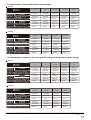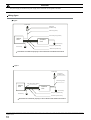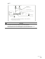
1
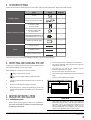
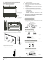
INSTALLATION
MANUAL
Ceiling And Floor Type
Thank you very much for purchasing our air conditioner,
Before using your air conditioner , please read this manual carefully and keep it for future reference.
Install according to this installation instructions strictly.
If installation is defective, it will cause water leakage,
electrical shock and fire.
CONTENTS
PAGE
When installing the unit in a small room, take measures
against to keep refrigerant concentration from exceeding
allowable safety limits in the event of refrigerant leakage.
Contact the place of purchase for more information.
Excessive refrigerant in a closed ambient can lead to oxygen
deficiency.
Use the attached accessories parts and specified parts
for installation.
otherwise, it will cause the set to fall, water leakage,
electrical shock and fire.
Install at a strong and firm location which is able to
withstand the set' s weight.
If the strength is not enough or installation is not properly
done, the set will drop to cause injury.
The appliance shall not be installed in the laundry.
Before obtaining access to terminals, all supply circuits
must be disconnected.
The appliance must be positioned so that the plug is
accessible.
The enclosure of the appliance shall be marked by word,
or by symbols, with the direction of the fluid flow.
keep this manual where the operator can easily find them.
Read this manual attentively before starting up the units.
For safety reason the operator must read the following
cautions carefully.
The safty precautions listed here are divided into two categories.
WARNING
If you do not follow these instrutions exactly, the unit may
cause property damage, personal injury or loss of life.
CAUTION
If you do not follow these instrutions exactly, the unit may
cause minor or moderate property damage, personal
injury.
After completing the installation, make sure that the unit operates
properly during the start-up operation. Please instruct the customer
on how to operate the unit and keep it maintained.Also, inform
customers that they should store this installation manual along with
the owner's manual for future reference.
WARNING
Be sure only trained and qualified service personnel to
install, repair or service the equipment.
Improper installation, repair, and maintenance may result in
electric shocks, short-circuit, leaks, fire or other damage to
the equipment.
For electrical work, follow the local national wiring
standard, regulation and this installation instructions. An
independent circuit and single outlet must be used.
If electrical circuit capacity is not enough or defect in
electrical work, it will cause electrical shock fire.
Use the specified cable and connect tightly and clamp
the cable so that no external force will be acted on the
terminal.
If connection or fixing is not perfect, it will cause heat-up or
fire at the connection.
Wiring routing must be properly arranged so that control
board cover is fixed properly.
If control board cover is not fixed perfectly, it will cause
heat-up at connection point of terminal, fire or electrical
shock.
If the supply cord is damaged, it must be replaced by the
manufacturer or its service agent or a similarly qualified
person in order to avoid a hazard.
An all-pole disconnection swith having a contact
separation of at least 3mm in all poles should be
connected in fixed wiring.
When carrying out piping connection, take care not to let
air substances go into refrigeration cycle.
Otherwise, it will cause lower capacity, abnormal high
pressure in the refrigeration cycle, explosion and injury.
Do not modify the length of the power supply cord or use
of extension cord, and do not share the single outlet with
other electrical appliances.
Otherwise, it will cause fire or electrical shock.
Carry out the specified installation work after taking into
account strong winds, typhoons or earthquakes.
Improper installation work may result in the equipment falling
and causing accidents.
installation manual
If the refrigerant leaks during installation, ventilate the
area immediately.
Toxic gas may be produced if the refrigerant comes into the
place contacting with fire.
The temperature of refrigerant circuit will be high, please
keep the interconnection cable away from the copper
tube.
After completing the installation work, check that the
refrigerant does not leak.
Toxic gas may be produced if the refrigerant leaks into the
room and comes into contact with a source of fire, such as a
fan heater, stove or cooker.
CAUTION
Ground the air conditioner.
Do not connect the ground wire to gas or water pipes,
lightning rod or a telephone ground wire.Inappropriate
grounding may result in electric shocks.
Be sure to install an earth leakage breaker.
Failure to install an earth leakage breaker may result in
electric shocks.
Connect the outdoor unit wires , then connect the indoor
unit wires.
You are not allowed to connect the air conditioner with the
power supply until the wiring and piping is done.
While following the instructions in this installation
manual, install drain piping in order to ensure proper
drainage and insulate piping in order to prevent
condensation.
Improper drain piping may result in water leakage and
property damage.
Install the indoor and outdoor units, power supply wiring
and connecting wires should be at least 1 meter away
from televisions or radios in order to prevent image
interference or noise.
Depending on the radio waves, a distance of 1 meter may not
be sufficient enough to eliminate the noise.
The appliance is not intended for use by young children
or infirm persons without supervision.
Don't install the air conditioner in the following
circumstance:
There is petrolatum existing.
There is salty air surrounding (near the coast).
There is caustic gas (the sulfide, for example) existing
in the air (near a hot spring).
The Volt vibrates violently (in the factories).
In buses or cabinets.
In kitchen where it is full of oil gas.
There is strong electromagnetic wave existing.
There are inflammable materials or gas.
There is acid or alkaline liquid evaporating.
Other special conditions.
installation manual
To install properly, please read this "installation manual" at
first.
The air conditioner must be installed by qualified persons.
When installing the indoor unit or its tubing, please follow
this manual as strictly as possible.
If the air conditioner is installed on a metal part of the
building, it must be electrically insulated according to the
relevant standards to electrical appliances.
When all the installation work is finished, please turn on
the power only after a thorough check.
Regret for no further announcement if there is any change
of this manual caused by product improvement.
INSTALLATION ORDER
Select the location;
Install the indoor unit;
Install the outdoor unit;
Install the connecting pipe ;
Connect the drain pipe;
Wiring;
Test operation.
Please check whether the following fittings are of full scope. If there are some spare fittings , please restore them carefully.
NAME
SHAPE
QUANTITY
1.Hook
2
2.Hanging arm(on some models)
2
3. Remote controller
(on some models)
1
4. Remote controller holder
(on some models)
1
Installation fittings
Remote controller & Its Holder
2
Others
6. Alkaline dry batteries (AM4)
2
7. Owner's manual
1
8. Installation manual
1
9. Remote controller manual
1
Both side covers may be installed on 42K-48K unit already, or be put into the accessories.
There is enough room for installation and maintenance.
At delivery, the package should be checked and any damage should
be reported immediately to the the service agent.
When handling the unit, take into account the following:
The ceiling is horizontal, and its structure can endure the
weight of the indoor unit.
The outlet and the inlet are not impeded, and the
influence of external air is the least.
The air flow can reach throughout the room.
1
Fragile, handle the unit with care.
Keep the unit upright in order to avoid compressor
damage.
2
Choose on before hand the path along which the unit is to be
brought in.
3
Move this unit as originally package as possible.
4
When lifting the unit , always use protectors to prevent belt
damage and pay attention to the position of the unit’s centre of
gravity.
The connecting pipe and drainpipe could be extracted out
easily.
There is no direct radiation from heaters.
≥35mm
Fig.5-1
5.1 Installation place
(Refer to Fig.5-1,Fig.5-2,Fig.5-3 and Table 5-1 for specification.)
The indoor unit should be installed in a location that meets
the following reauirements:
CAUTION
Keep indoor unit, outdoor unit, power supply wiring and
transmission wiring at least 1 meter away from televisions
and radios. This is to prevent image interference and
noise in those electrical appliances. (Noise may be
generated depending on the conditions under which the
electric wave is generated, even if 1 meter is kept.)
installation manual
5.2.2
5.2 Install the main body(the unit with the
water pump is not included)
5.2.1
1
Wall Mounting Installtion
Ceiling Installation
Installing Ø10 hanging screw bolts. (4 bolts)
Please Refer to Fig.5-3 and Fig.5-4 for the hanging screw
bolts distance
Evaluate the ceiling construction and please install with Ø10
hanging screw bolts.
The handling to the ceiling varies from the constructions,
consult the construction person for the specific condition.
Do keep the ceiling flat. Consolidate the roof beam to avoid
possible vibration.
Cut off the roof beam.
D. Connecting point of
refrigerant pipe
(D. gas side)
Drain point
E. Connecting point of
refrigerant pipe
Strengthen the place that has been cut off, and
consolidatethe roof beam.
After the selection of installation location, position the refrigerant
pipes, drain pipes,indoor & outdoor wires to the connection
places before hanging up the machine.
The installation of hanging screw bolts.
(E. Liquid side)
WOODEN CONSTRUCTION
C
Put the square timber traversely overthe roof beam, then install
the hanging screw bolts.
D
Hook
Timber over the beam
Roof beam
Ceiling
Hanging screw bolts
Fig.5-5
NEW CONCRETE BRICKS
Fig. 5-2
Inlaying or embedding the screw bolts.
1 Fix the hook with tapping screw onto the wall.(Refer to Fig.5-3)
(Blade shape
insertion)
(Slide insertion)
Fig.5-6
Hook
Steel bar
Embedding screw bolt
Tapping
screw
(Pipe hanging and embedding screw bolt)
Washer
Fig.5-7
FOR ORIGINAL CONCRETE BRICKS
<6mm
Install the hanging hook with expansible bolt into the concrete
deep to 45~50mm to prevent loose.
Fig.5-3
2 Hang the indoor unit on the hook.
Fig.5-8
(The bottom of body can touch with floor or suspended, but the
body must install vertically.)
STEEL ROOF BEAM STRUCTRUE
Install and use directly the supporting angle steel.
Hanging screw bolt
Hanging
bolts
Fig.5-4
installation manual
Supporting
angle steel
Fig.5-9
2
For some of the models 60 please securely tighten the mounting
bolts on both sides.(Refer to Fig5-15).
Install the indoor unit.
Hanging
screw bolt
Fig. 5-15
Hanging arm
Fig.5-10
Remove the side board and the grille.(Refer to Fig. 5-10)
(For models 48 and 60, do not remove the grille.)
Fig. 5-16
D. Connecting point of
refrigerant pipe
(D.gas side)
E. Connecting point of
refrigerant pipe
(E. Liquid side)
Side board
G
Grille
Fig. 5-11
Locate the hanging arm on the hanging screw bolt.
(Refer to Fig. 5-12)(for some of the models 60 do not do this)
Prepare the mounting bolts on the unit.( Refer to Fig. 5-13)
Drain point
Fig. 5-17
5.3
Screw nut
Washer
Hanging
screw bolt
Fig.5-12
Hanging arm
Table 5-1
MODEL
12~24
30~36
48
60
60
unit:mm
A
990
1280
1670
1670
1670
B
660
660
680
680
680
C
D
203 505
203 795
240 1070
240 1070
285 1070
G
F
907 200
1195 200
1542 200
1542 200
1613 220
E
506
506
450
450
380
8~13mm
INDOOR UNIT
Mounting bolt(max.40mm)
Fig. 5-13
Hang the unit on the hanging arm by sliding backward. Securely
tighten the mounting bolts on both sides.(Refer to Fig. 5-14)
(some of the models 60 do not do this)
6.1 Installation Place
The outdoor unit should be installed in the location that
meets the following requiements:
There is enough room for installation and maintenance.
The air outlet and the air inlet are not impeded, and can
not be reached by strong wind.
It must be a dry and well ventilating place.
The support is flat and horizontal and can stand the
weight of the outdoor unit. And will no additional noise or
vibration.
Your neighborhood will not feel uncomfortable with the
noise or expelled air.
It is easy to install the connecting pipes or cables.
Determine the air outlet direction where the discharged
air is not blocked.
Fig. 5-14
There is no danger of fire due to leakage of inflammable
gas.
installation manual
The piping length between the outdoor unit and the indoor
unit may not exceed the allowable piping length.
6.2 Figure of body size
In the case that the installation place is exposed to strong
wind such as a seaside, make sure the fan operating
properly by putting the unit lengthwise along the wall or
using a dust or shield.(Refer to Fig.6-1)
1. Split type outdoor unit
If possible, do not install the unit where it is exposed to
direct sunlight.
If necessary, install a blind that does not interfere with the
air flow.
During the heating mode, the water drained off the
outdoor unit ,The condensate should be well drained
away by the drain hole to an appropriate place, so as not
to interfere other people.
Select the position where it will not be subject to snow
drifts, accumulation of leaves or other seasonal debris. If
unavoidable, please cover it with a shelter.
Locate the outdoor unit as close to the indoor unit as
possible.
A
If possible, please remove the obstacles nearby to
prevent the performance from being impeded by too little
of air circulation.
The minimum distance between the outdoor unit and
obstacles described in the installation chart does not
mean that the same is applicable to the situation of an
airtight room. Leave open two of the three
directions.(Refore to Fig.6-7, Fig.6-8, Fig.6-9)
Fig.6-2
A
Fig.6-1
NOTE
The dimension of 12 and 24 are the same
The dimension of 30 and 36 are the same
The dimension of 48 and 60 are the same
mm
Fig.6-3
Fig.6-4
installation manual
Table 6-1
3. Centrifugal fan type outdoor unit
unit:mm
MODEL
A
B
C
D
E
F
H
REMARK
12
762
530
290
315
270
282
593
Fig.6-2
762
530
290
315
270
282
593
Fig.6-2
842
560
335
360
312
324
695
Fig.6-2
852
582
368
390
328
340
660
Fig.6-2
895
590
333
355
302
313
862
Fig.6-2
990
624
366
396
340
354
966
Fig.6-2
990
624
366
396
340
354
966
Fig.6-2
895
590
333
355
302
313
862
Fig.6-2
990
624
366
396
340
354
966
Fig.6-2
940
600
376
400
340
360
1245
Fig.6-3
990
624
366
396
340
354
966
Fig.6-2
940
600
376
400
340
360
1245
Fig.6-3
A
B
E
18
24
H
C
D
Fig.6-7
unit:mm
Table 6-3
A
30
36
42
B
C
D
E
F
G
H
I
J
18
1174 1120 680
720
750
475
300
430
265
393
24
1174 1120 680
720
750
475
300
430
265
393
30
1381 1328 702
740
770
520
336
500
296
443
36
1381 1328 702
740
770
520
336
500
296
443
48
1394 1338 783
820
850
568
398
574
342
463
60
1394 1338 783
820
850
568
398
574
342
463
6.3 Space of installation and maintenance
Fig.6-2
1. Split type outdoor unit
Fig.6-3
48
(Wall or obstacle)
Fig.6-3
Air inlet
Fig.6-3
>30cm
60
N
Fig.6-3
Maintain channel
Air inlet
>60cm
P
M
2. Vertical discharge type outdoor unit
Air outlet
Fig.6-8
C
2. Vertical discharge type outdoor unit
(Wall or obstacle)
A
Fig.6-5
Table 6-2
B
Fig.6-6
Fig.6-9
unit:mm
(Wall or obstacle)
>30cm
Refore to
Fig.6-5
Fig.6-6
Air inlet
>30cm
Air inlet
Fig.6-10
installation manual
3. Centrifugal fan type outdoor unit
To change air outlet is necessary to interchange panels too.
a) In case that suspending in the ceiling
Fan outlet panel is attached to fan structure, which must be
mounted as follow.
Fig.6-14
6.5 Moving and installation
Fig.6-11
Since the gravity center of the unit is not at its physical
center, so please be careful when lifting it with a sling.
b)In case that installing on the floor
Never hold the inlet of the outdoor unit to prevent it from
deforming.
Do not touch the fan with hands or other objects.
Do not lean it more than 45, and do not lay it sidelong.
Make concrete foundation accoding to the sepecif-ications of
the outdoor units.(Refer to Fig.6-15)
Fasten the feet of this unit with bolts firmly to prevent it from
collapsing in case of earthquake or strong wind.(Refer to
Fig.6-15)
Fig.6-12
NOTE
Fix with bolt
All the figures in this manual are for explanation
purpose only. They may be slightly different from the air
conditioner you purchased.The actual unit shall prevail.
Fig.6-15
Concrete Foundation
6.4 Available configuration
Four different configuration are available for oudoor unit only
1. Foundation could be on flat and is recommended be 100-300mm
higher than ground level.
changing the panels and fan position.
2.Install a drainage around foundation for smooth drain
NOTE
3.When installing the outdoor unit fix the unit by anchor bolts of M10
Keep in mind that fan unit weight is aprox 30g ,the unit as
well as relevant equipment covered with the vinyl cover
4.When installing the unit on a roof or a veranda, drain water
sometimes turns to ice on a cold morning. Therefore, avoid
during installation work.
draining in an area that people often use because it is slippery.
Air inlet modification
To change air inlet is only necessary to interchange the
indicated panels position. Both panels use screws to be fixed
to unit chassis.
≥100
B
Change Panel
Fig6-13
installation manual
C
Fig.6-16
Table 6-4
No
1
2
3
Description
Check whether the height drop between the indoor unit and
outdoor unit, the length of refrigerant pipe, and the number of
the bends meet the following requirements:
(The number of the bends less than 15)
Outdoor Unit
Vibration-proof rubber
Anchor Bolt M10
4
5
Drainage (Wide 100×Depth 150)
6
Mortar Hole (Φ100×Depth 150)
Table 7-1
Drainage
The type of models
50Hz T1 condition/R22
Split type air conditioner
Table 6-5
MODEL
18~24
unit:mm
B
1120
/60Hz T1 condition/R22 Split type air
C
conditioner and Vertical discharge air
conditioner
720
30
1328
740
36
1328
740
48~60
50Hz Vertical discharge air conditioner
R410A inverter Split type air
conditioner and and Centrifugal
fan outdoor unit
1338
820
8
30
10
30K-42K
50
20
48K-60K
50
25
12K
15
8
18K-24K
30
10
30K-60K
30
20
12K
10
5
18K-24K
25
12
30K
25
15
36K
30
20
50
25
15
8
18K-30K
25
15
36K
30
20
48K-60K
50
25
18K-24K
25
10
50Hz/60Hz T3 condition
30K
30
15
(outdoor unit down)
36K
30
20
42K-60K
50
25
18K-24K
25
15
30K
30
20
36K
30
25
42K
50
30
48K-60K
50
35
12K-18K
5
5
unit
1. Suspend the unit as the drawing indicates.
in specification label plate.
15
12K
and and Centrifugal fan outdoor
2. Ensure that ceiling can resist the Outdoor unit weight indicated
12K
18K-24K
48K-60K
R410A Split type air conditioner
Suspended unit
Model
50Hz/60Hz T3 condition
Sling Bolt
(outdoor unit up)
the unit with quick joint
Suspension Bracket
7.1 The Procedure of Connecting Pipes
CAUTION
Fig.6-17
All field piping must be provided by a licensed
refrigeration technician and must comply with the
relevant local and national codes.
Do not let air, dust, or other impurities fall in the pipe
system during the time of installation.
The connecting pipe should not be installed until the
indoor and outdoor units have been fixed already.
Keep the connecting pipe dry, and do not let moisture in
during installation.
Execute heat insulation work completely on both sides
of the gas piping and the liquid piping. Otherwise, this
can sometimes result in water leakage.
1
Drill a hole in the wall (suitable just for the size of the wall
conduit), then set on the fittings such as the wall conduit and
its cover.
installation manual
2
Bind the connecting pipe and the cables together tightly with
binding tapes.Pass the bound connecting pipe through the
wall conduct from outside. Be careful of the pipe allocation to
do on damage to the tubing.
3
Connect the pipes. Refer to "How to Connect the pipes" for
details.
4
Expel the air with a vacuum pump. Refer to "How to expel the
air with a vacuum pump" for details.
5
Open the stop values of the outdoor unit to make the
refrigerant pipe connecting the indoor unit with the outdoor
unit in fluent flow.
6
Check the leakage. Check all the joints with the leak detector
or soap water.
7
Cover the joints of the connecting pipe with the soundproof /
insulating sheath (fittings), and bind it well with the tapes to
prevent leakage.
3
Remove the protection cover of stop valve
Liquid Valve
Gas Valve
4
Fig.7-3
Connect the indoor unit at first, then the outdoor
unit.
Bend the tubing in proper way. Do not harm to them.
Bend the pipe with thumb
CAUTION
Be sure to with insulating materials cover all the exposed
parts of the flare pipe joints and refrigerant pipe on the
liquid-side and the gas-side. Ensure that there is no gap
between them.
Incomplete insulation may cause water condensation.
min-radius 100mm
Bending position is preferably in the middle of the
bendable pipe. The larger the bending radius the better it
is.
How to Connect the pipes
1
Do not bend the pipe more than three times.
When connecting the flare nut, coat the flare both inside
and outside with either oil or ester oil and initially tighten
by hand 3 or 4 turns before tighting firmly.
Flaring
Cut a pipe with a pipe cutter. (Refer to Fig.7-1)
Lean
crude
Fig.7-4
The bending angle should not exceed 90.
burr
Fig.7-5
Be sure to use both a spanner and torque wrench
together when connecting or disconnecting pipes to /from
the unit.
Fig.7-1
Insert a flare nut into a pipe and flare the pipe.
Refer to Table 7-2 for the dimension of flare nut spaces.
Table 7-2
Pipe gauge Tightening
2
torque
Flare dimensin A
min
max
Ø6.4
15~16 N.m
(153~163 kgf.cm)
8.3
8.7
Ø9.5
25~26N.m
(255~265 kgf.cm)
12.0
12.4
Flare
Fig.7-6
shape
CAUTION
90 °± 4
Too large torque will harm the bellmouthing and too small
will cause leakage. Please determine the torque
according to Table 7-2.
After the connecting work is finished, be sure to check
that there is no gas leak.
A
Ø12.7
35~36 N.m
(357~367 kgf.cm)
15.4
15.8
Ø15.9
45~47 N.m
(459~480 kgf.cm)
18.6
19.0
Ø19.1
65~67N.m
(663~684 kgf.cm)
22.9
23.3
R0.4~0.8
How to expel the air with a vacuum pump
Remove the Cycle Service Panel and the Cover
Board, unscrewing the screws which secure it to
the structure
Stop valve operation introduction
1.
Opening stop valve
1.
Remove the cap and turn the valve
counterclock-wise with the hexagon wrench.
2.
Turn it until the shaft stops.Do not apply excessive force
to the stop valve. Doing so may breakthe valve body, as
the valve is not a backseat type. Always use the special
tool.
3.
Make sure to tighten the cap securely.
Cycle Service Panel
Cover Board
installation manual
Fig.7-2
2.
Closing stop valve
1. Remove the cap and turn the valve clockwise with the
hexagon wrench.
Manifold valve
Multi-meter
Pressure meter
-76 cmHg
2. Securely tighten the valve until the shaft contacts the
main bodyseal.
Lo-lever
Hi-lever
Charge hose
Charge hose
Make sure to tighten the cap securely.
For the tightening torque, refer to the table below.
Vacuum pump
Table 7-3
Tightening torque N M (Turn clockwise to close)
Stop
Valve size
Ø6.4
Ø9.5
Shaft (valve body)
5~7
Hexagonal
wrench 4 mm
Fig.7-9
Lo-lever
Cap
(Valve lid)
7.2 Additional Refrigerant Charge
13.5~16.5
CAUTION
Ø12.7
7~9
Ø15.9
9~11
Hexagonal
wrench 6 mm
23~27
Ø19.1
11~13
Hexagonal
wrench 6 mm
35~40
18~22
Refrigerant cannot be charged until field wiring has been
completed.
11.5~13.9
Refrigerant may only be charged after performing the leak
test and the vacuum pumping.
CAUTION
Always use a charge hose for service port connection
After tightening the cap, check that no refrigerant leaks
arepresent.
service port
When charging a system, care shall be taken that its
maximum permissible charge is never exceeded, in view of
the danger of liquid hammer.
Charging with an unsuitable substance may cause
explosions and accidents, so always ensure that the
appropriate refrigerant is charged.
maintenance nut
Refrigerant containers shall be opened slowly.
Always use protective gloves and protect your eyes when
charging refrigerant.
cap
seal
shaft hexagon hole
Fig.7-7
Using the vacuum pump
1
Loosen and remove the maintenance nuts of stop valves A
and B, and connect the charge hose of the manifold valve to
the service port of stop valve A. (Be sure that stop valves A
and B are both closed)
The outdoor unit is factory charged with refrigerant. Calculate
the added refrigerant according to the diameter and the
length of the liquid side pipe of the outdoor unit/indoor unit
connection.(suitable for throttle outdoor unit)
Table 7-4
Brass tube(mm)
Ø6.35
2
Connect the joint of the charge hose with the vacuum pump.
3
Open the Lo-lever of the manifold value completely.
4
Turn on the vacuum pump. At the beginning of pumping,
loosen the maintenance nut of stop valve B a little to check
whether the air comes in (the sound of the pump changes,
and the indicator of compound meter turns below zero). Then
fasten the maintenace nut.
5
When the pumping has finished, close the Lo-lever of the
manifold valve completely and turn off the vacuum
pump.Make pumping for 15 minutes or more and check that
5
the compound meter indicates -76cmHg(-1X10 Pa)
6
Loosen and remove the cap of stop valves A and B to open
stop valve A and B completely, then fasten the cap.
7
Disassemble the charge hose from the service port of stop
valve A, and fasten the nut.
Outdoor
unit
A
Indoor
unit
Gas side
C
Liquid side
D
Ø9.53
Ø12.7
R410A
R22
0.022kg/m×(L-5)
0.030kg/m×(L-5)
0.011kg/m×(L-5)
0.015kg/m×L
0.060kg/m×(L-5)
0.065kg/m×(L-5)
0.030kg/m×(L-5)
0.030kg/m×L
0.110kg/m×(L-5)
0.115kg/m×(L-5)
0.060kg/m×(L-5)
0.060kg/m×L
0.170kg/m×(L-5)
0.190kg/m×(L-5)
0.085kg/m×(L-5)
0.095kg/m×L
0.250kg/m×(L-5)
0.290kg/m×(L-5)
0.125kg/m×(L-5)
0.145kg/m×L
Ø15.9
Ø19.0
NOTE
If a negative result is gotten for R from Table 7-4, no
refrigerant needs to be added nor removed.
Additional refrigerant will be twice of R from Table 7-4 if
the indoor unit installed throttle assembly.
B
Stop valve
Fig.7-8
Install the drainpipe of the indoor unit
The outlet has PTI screw bread, Please use sealing materials
and pipe sheath(fitting) when connecting PVC pipes.
installation manual
CAUTION
The drain pipe of indoor unit must be heat insulated, or it will
condense dew, as well as the connections of the indoor unit.
Hard PVC binder must be used for pipe connection, and make
sure there is no leakage.
With the connection part to the indoor unit, please be noted not
to impose pressure on the side of indoor unit pipes.
Drain Piping
When the declivity of the drain pipe downwards is over 1/100,
there should not be any winding.
The total length of the drain pipe when pulled out traversely
shall not exceed 20m, when the pipe is over long, a prop stand
must be installed to prevent winding.
Refer to the Fig.8-1 for the installation of the pipes.
1.5m~2m
Insulating
material
Fig.8-2
unit:mm
Table 8-1
MODEL
A
B
18~24
595
1200
36
624
1381
48~60
646
1385
Prepare a polyviny chloride with 21mm inner diameter
Downward declivity
lower than 1/100
Fasten the tube to the drain hose with an adhesive and the
field-supplied clamp. The drain piping must be performed with
a DOWN-SLOPE pitch of 1/25 to 1/100
Bend
Connect a siphon, as shown in figure below
S shape
75
Slope 2 %
Put as deep as possib le
(about 10cm)
Plug
Fig.8-3
Downw ard declivity
lower t han 1/100
Fig. 8-1
VP30
NOTE
All the figures in this manual are for explanation purpose only.
They may be slightly different from the air conditioner you
purchased.The actual unit shall prevail.
Drainage test
Check whether the drainpipe is unhindered.
New built house should have this test done before
paving the ceiling.
Install the drain joint of the outdoor unit
Fit the seal into the drain joint, then insert the drain joint into
0
the base pan hole of outdoor, rotate 90 to securely
assemble them. Connect the drain joint with an extension
drain hose (Locally purchased), in case of the condensate
draining off the outdoor unit during the heating mode.(Refer
to Fig.8-2)
The appliance shall be installed in accordance with
national wiring regulations.
The air conditioner should use separate power supply
with rated voltage.
The external power supply to the air conditioner should
have ground wiring, which is linked to the ground wiring
of the indoor and outdoor unit.
The wiring work should be done by qualified persons
according to circuit drawing.
Seal
Drain joint
An all-pole disconnection device which has at least 3mm
sepaaration distance in all pole and a residual current
device (RCD) with the rating of above 10mA shall be
incorporated in the fixed wiring according to the national
rule.
The base pan hole
of outdoor unit
Be sure to locate the power wiring and the signal wring
well to avoid cross-disturbance.
Seal
The base pan
of outdoor unit
Drain
joint
Fig.8-2
Outdoor unit is equiped with a drain piping. Its position is
shown figure below
installation manual
Do not turn on the power until you have checked
carefully after wiring.
The power cord type designation is H07RN-F.
NOTE
NOTE
All the figures in this manual are for explanation
purpose only. They may be slightly different from the air
conditioner you purchased.The actual unit shall prevail.
Remark per EMC Directive 2004/108/EC.
For to prevent flicker impressions during the start of the
compressor (technical process) ,following installation
conditions do apply.
1
2
3
Connect the connective cables to the terminals as identified
with their respective mached numbers on the terminal block
of indoor and outdoor units.
The power connection for the air conditioner has to be
done at the main power distribution. The distribution has
to be of a low impedance, normally the required
impedance reaches at a 32 A fusing point.
No other equipment has to be connected with this power
line.
For detailed installation acceptance please refer to your
power supplier, if restrictions do apply for products like
washing machines, air conditioners or electrical ovens.
4
For power details of the air conditioner refer to the rating
plate of the product.
5
For any question contact your local dealer.
9.1 Connect the cable
Re-install the cover or the protection board.
9.2 The Specification of Power
(Refer to Table9-1~Table 9-15)
9.3 Wiring figure
(Refer to Fig.9-4~Fig.9-36)
1
The test operation must be carried out after the entire
installation has been completed.
2
Please confirm the following points before the test operation:
The indoor unit and outdoor unit are installed properly.
Dissemble the bolts from the cover.(If there isn't a cover on
the outdoor unit, disassemble the bolts from the maintenance
board, and pull it in the direction of the arrow to remove the
protection board.) (Refer to Fig.9-1, Fig.9-2, Fig.9-3)
Tubing and wiring are correctly completed.
The refrigerant pipe system is leakage-checked.
The drainage is unimpeded.
Split type outdoor unit
The heating insulation works well.
The ground wiring is connected correctly.
The length of the tubing and the added stow capacity of
the refrigerant have been recorded.
Cover
The power voltage fits the rated voltage of the air
conditioner.
There is no obstacle at the outlet and inlet of the outdoor
and indoor units.
The gas-side and liquid-side stop valves are both opened.
The air conditioner is pre-heated by turning on the power.
Protection board
3
According to the user's requirement, install the remote
controller frame where the remote controller's signal can
reach the indoor unit smoothly.
4
Test operation
Fig.9-1
Vertical discharge type outdoor unit
Set the air conditioner under the mode of "COOLING" with
the remote controller, and check the following points. If there
is any malfunction, please resolve it according to the chapter
"Troubleshooting" in the "Owner's Manual".
Protection Board
Fig.9-2
Centrifugal fan outdoor unit
1) The indoor unit
a. Whether the switch on the remote controller works well.
b. Whether the buttons on the remote controller works
well.
c. Whether the air flow louver moves normally.
d. Whether the room temperature is adjusted well.
e. Whether the indicator lights normally.
f. Whether the temporary buttons works well.
g. Whether the drainage is normal.
h. Whether there is vibration or abnormal noise during
operation.
I. Whether the air conditioner heats well in the case of the
HEATING/COOLING type.
2) The outdoor unit
a. Whether there is vibration or abnormal noise during
operation.
b. Whether the generated wind, noise, or condensed of by
the air conditioner have influenced your neighborhood.
c. Whether any of the refrigerant is leaked.
CAUTION
Protection Board
Fig.9-3
A protection feature prevents the air conditioner from being
activated for approximately 3 minutes when it is restarted
immediately after shut off.
installation manual
The Specification of Power(indoor power supply)
Table 9-1
18
24
30~36
42~48
60
1Phase
1Phase
1Phase
1Phase
1Phase
208-240 V
208-2 40V
208-2 40V
208-2 40V
208-2 40V
20/16
40/25
50/30
60/45
60/50
Table 9-2
30~36
42~60
30~36
42~60
3Phase
3Phase
3Phase
3Phase
380-420 V
380-420 V
208-2 40V
208-2 40V
25/20
25/20
40/25
45/35
The Specification of Power(outdoor power supply)
Table 9-3
24
30~36
42~48
60
1Phase
1Phase
1Phase
1Phase
208-2 40V
208-2 40V
208-2 40V
208-2 40V
40/30
60/40
70/55
70/60
Table 9-4
installation manual
30~36
42~60
30~36
42~60
3Phase
3Phase
3Phase
3Phase
380-420 V
380-420 V
208-2 40V
208-2 40V
25/20
25/20
40/25
45/35
The Specification of Power(independence power supply)
Table 9-5
18
24
30~36
42~48
60
1Phase
1Phase
1Phase
1Phase
1Phase
208-240 V
208-2 40V
208-2 40V
208-2 40V
208-2 40V
20/16
20/16
20/16
20/16
20/16
1Phase
1Phase
1Phase
1Phase
1Phase
208-240 V
208-2 40V
208-2 40V
208-2 40V
208-2 40V
20/16
40/25
50/30
60/45
60/50
Table 9-6
30~36
42~60
30~36
42~60
1Phase
1Phase
1Phase
1Phase
208-2 40V
208-2 40V
208-2 40V
208-2 40V
20/16
20/16
20/16
20/16
3Phase
3Phase
3Phase
3Phase
380-420 V
380-420 V
208-2 40V
208-2 40V
25/20
25/20
40/25
45/35
The Specification of Power for the invert type air conditioner(independence power supply)
Table 9-7
18
24
30~36
42~48
60
1Phase
1Phase
1Phase
1Phase
1Phase
220-240 V
220-2 40V
220-2 40V
220-2 40V
220-2 40V
15/10
15/10
15/10
15/10
15/10
1Phase
1Phase
1Phase
1Phase
1Phase
208-240 V
208-2 40V
208-2 40V
208-2 40V
208-2 40V
30/20
30/20
40/30
40/35
50/40
Table 9-8
30~36
42~60
30~36
42~60
1Phase
1Phase
1Phase
1Phase
220-2 40V
220-2 40V
220-2 40V
220-2 40V
15/10
15/10
15/10
15/10
3Phase
3Phase
3Phase
3Phase
380-420 V
380-420 V
208-2 40V
208-2 40V
30/20
30/25
50/40
50/40
installation manual
CAUTION
The power supply is included in the power supply above mentioned can be applied to the table.
Wiring figure
Fig.9-5
Power supply
Switch/Fuse
(Available locally)
Power wiring (indoor)
Power linking wiring (Outdoor)
Indoor
Unit
Outdoor
Unit
Ground wiring
Strong elec-signal link wiring
Ground wiring
Weak elec-signal link wiring
Ground the air conditioner properly in case to affect its anti-interference function
Fig.9-6
Power supply
Switch/Fuse
(Available locally)
Power wiring (indoor)
Power linking wiring (Outdoor)
Indoor
Unit
Outdoor
Unit
Ground wiring
Ground wiring
Strong elec-signal link wiring
Weak elec-signal link wiring
Ground the air conditioner properly in case to affect its anti-interference function
installation manual
Fig.9-7
Power supply
Power supply
Switch/Fuse
(Available locally)
Power wiring (indoor)
Power linking wir ing (Outdoor)
Indoor
Unit
Out door
Unit
Ground wiring
Weak elec-signal link wiring
Ground wiring
Ground the air conditioner properly in case to affect its
anti-interference function
CAUTION
A disconnection device having an air gap contact separation in all active conductors should be
incorporated in the fixed wiring according to the National Wiring Regulation.
When wiring, please choose the corresponding chart, or it may cause damage.The signs of the
indoor terminal block in the some of following fugures may be replaced by L N L1 N1.
installation manual
QSDLI-015AEN
202000192505
2012.06.13
installation manual
installation manual
installation manual
installation manual
installation manual