1
A50-37130-08001
PROFESSIONAL
BTX36000
User Manual
en
Important safety
instructions
CAUTION: High voltage! Risk of death! To avoid lethal electric
shock, do not open the casing. There are no user-serviceable
components inside. Refer all maintenance to qualified service
personnel. Remove the mains cable when the unit is not in use.
10) Protect the power cord from being walked on or
pinched particularly at plugs, convenience receptacles, and the point where they exit from the apparatus.
11) Only use attachments/accessories specified by the
manufacturer.
12) Use only with the cart, stand, tripod, bracket, or
table specified by the manufacturer, or sold with the
apparatus. When a cart is used, use caution when
moving the cart/apparatus combination to avoid injury from tip-over.
WARNING: To eliminate the risk of fire and electric shock, do not
expose this unit to rain or moisture and splashing or dripping liquid,
which might enter the device. Do not place any objects filled with
liquid, such as vases, on the unit.
**
!!
1)
2)
3)
4)
5)
6)
7)
8)
9)
en
2
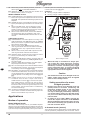
This symbol, wherever it appears, alerts
you to the presence of uninsulated dangerous voltage inside the enclosure—voltage that may be sufficient to constitute a
risk of shock.
This symbol, wherever it appears, alerts
you to important operating and maintenance instructions in the accompanying
literature. Please read the manual.
Read these instructions.
Keep these instructions.
Heed all warnings.
Follow all instructions.
Do not use this apparatus near water.
Clean only with dry cloth.
Do not block any ventilation openings. Install in accordance with the manufacturer’s instructions.
Do not install near any heat sources such as radiators, heat registers, stoves, or other apparatus
(including amplifiers) that produce heat.
Do not defeat the safety purpose of the polarized
or grounding-type plug. A polarized plug has two
blades with one wider than the other. A grounding type plug has two blades and a third grounding prong. The wide blade or the third prong are
provided for your safety. If the provided plug does
not fit into your outlet, consult an electrician for
replacement of the obsolete outlet.
13) Unplug this apparatus during lightning storms or
when unused for long periods of time.
14) Refer all servicing to qualified service personnel.
Servicing is required when the apparatus has been
damaged in any way, such as power supply cord or
plug is damaged, liquid has been spilled or objects
have fallen into the apparatus, the apparatus has
been exposed to rain or moisture, does not operate
normally, or has been dropped.
15) The apparatus shall be connected to a MAINS socket outlet with a protective earthing connection.
16) Where the MAINS plug or an appliance coupler is
used as the disconnect device, the disconnect device shall remain readily operable.
17) CAUTION! - These service instructions are for use
by qualified service personnel only. To reduce the
risk of electric shock do not perform any servicing
other than that contained in the operation instructions unless you are qualified to do so.
Table of contents
IMPORTANT NOTICE!
IMPORTANT NOTICE!..............................3
FAILURE TO OBSERVE THE FOLLOWING POINTS MAY RESULT IN DAMAGE TO THE AMPLIFIER OR LOUDSPEAKERS.
DAMAGE CAUSED IN SUCH A WAY ARE NOT COVERED BY
WARRANTY.
Introduction..............................................3
Before you get started............................................. 3
Online registration................................................... 4
Control elements and connections........4
Front panel.............................................................. 4
Rear panel............................................................... 5
Applications.............................................6
Modes of operation.................................................. 6
Mono-bridged mode...................................................... 6
2-channel mode (stereo)............................................... 6
Parallel mode................................................................ 7
Bi-amping................................................................ 7
The compressor....................................................... 7
About speaker impedance....................................... 7
Installation................................................8
Rack mounting......................................................... 8
$$
Observe the correct impedance for your
loudspeaker and use the appropriate output
socket.
$$
Always use loudspeaker cables for connection between the amplifier and the loudspeaker. Never use other types of cable such
as instrument cable and microphone cable.
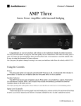
Introduction
Thank you for choosing the BUGERA BTX36000 bass amplifier
head. “THE NUKE” delivers massive 2 x 1,800 Watts in stereo
mode or 3,800 Watts in mono-bridged mode. We have fitted the
BTX36000 out with an active 9-band graphic EQ to make sure
that so much power can be tailored exactly to the frequency range
you want to apply to it. An integrated compressor increases the
sustain and smoothes out volume peaks while the Bright function
enhances the sound. A switchable Limiter provides distortionfree sound at all levels. In addition, the BTX36000 features
comprehensive connectivity including balanced DI outputs for
direct connection to a mixing console plus a Tuner output on the
front and rear panel. The independent DC and thermal overload
protection on each channel keeps the system safe and sound.
Before you get started
Your product was carefully packed at the factory to ensure safe
transport. Nevertheless, if the box is damaged inspect the unit
immediately for signs of damage.
$$
If the unit is damaged please do NOT return it
to us, but notify your dealer and the shipping
company immediately, otherwise, claims for
damage or replacement may not be granted.
$$
Always use the original box to prevent damage during storage or transport.
$$
Make sure that children cannot play unsupervised with the unit or its packaging.
$$
Please ensure proper disposal of all packing
materials.
Audio connectors..................................................... 8
Footswitch connector............................................... 9
Specifications........................................10
System block diagram..........................11
Limited warranty....................................12
Ensure adequate air supply and to avoid overheating do not
place the unit near radiators etc.
$$
Please make sure that all devices are properly grounded. For your own safety, never remove or disable the ground conductors from
the devices or on the power cords. The unit
must always be connected to the mains outlet with a protective grounding connection.
Important notes concerning
installation
$$
The sound quality may diminish within the
range of powerful broadcasting stations and
high-frequency sources. Increase the distance between the transmitter and the device and use shielded cables for all connections.
3
en
Online registration
Please do remember to register your new BUGERA equipment
right after your purchase by visiting www.bugera-amps.com and
kindly read the terms and conditions of our warranty carefully.
Should your BUGERA product malfunction, our goal is to have
it repaired as quickly as possible. To arrange for warranty service, please contact the retailer from whom the equipment was
purchased. Should your BUGERA dealer not be located in your
vicinity, you may directly contact the BEHRINGER company
nearest to you. This contact information is included in the original
equipment packaging (Global Contact Information/European
Contact Information).
Registering your purchase and equipment with us helps us process
your repair claims quicker and more efficiently.
Thank you for your cooperation!
Control elements and connections
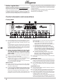
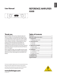
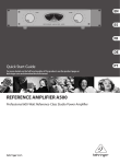
Front panel
Front panel control elements
level is too high, the (CLIP) LED warns that clipping can
occur. If the LED:
== occasionally illuminates, the BTX clips only
some peaks in the audio signal. Occasional
clipping does not reduce the sound quality and
shows that the signal is strong enough.
== never illuminates, the BTX does not clip any
signal peaks in the audio signal. The audio signal is probably too weak to make use of the full
dynamic range. Increase the GAIN (6) setting
until the (CLIP) LED lights up only occasionally,
at the strongest signal peaks.
== constantly illuminates, the BTX clips a large
part of the audio signal and you will hear a
distortion. Lower the GAIN setting and check
for extreme fader or control settings.
{1} Use the POWER switch to switch the BTX36000 on and off.
You should always make sure that the POWER switch is in
the “Off” position when initially connecting the unit to the
mains.
To disconnect the unit from the mains, pull out the main
cord plug. When installing the product, ensure that the plug
is easily accessible. If mounting in a rack, ensure that the
mains can be easily disconnected by a plug or by an all-pole
disconnect switch on or near the rack.
$$
Please note that switching the unit off does
not fully disconnect it from the mains. When
not using the unit for a long period of time,
please unplug the unit’s power cord from the
power outlet.
en
{2} INPUT: To connect an electric bass to the BUGERA amplifier,
use this ¼" mono jack (unbalanced).
{3} TUNER OUTPUT jack: To connect the BTX36000 to an
electronic tuner, use this ¼" TS jack. Alternatively, use the
TUNER OUTPUT (36) found on the rear panel.
You can mute the main signal path to tune your instrument
by pressing the MUTE button {4}.
INPUT features
{4} MUTE: Use this button if you want to tune a bass without
hearing the tone. This feature mutes the main signal path,
but not the TUNER output.
{6} GAIN control: Use this control to boost or cut the level of the
input signal.
COMPRESSOR section
{7} The ON [ACTIVE] switch activates and deactivates the compressor. The switch lights when the compressor is active and
the light dims when the signal level exceeds the threshold.
{8} The COMPRESSION control determines the compression
level. You can adjust the amount of compression between
0 and 10:1.
EQUALIZER section
{5} -15 dB: If the (CLIP) LED (5) constantly illuminates and the
GAIN control (6) is set to 0 (zero), the input level of the audio
signal is too high. In this case, press this button to activate
the pad. The pad reduces the input sensitivity by 15 dB.
{9} The ULTRA HIGH switch boosts the frequency range centered at 5 kHz by 6 dB.
(11) BASS, MID, and TREBLE controls: For each tone (bass, midrange, and treble) that you can emphasize or de-emphasize,
the BTX includes a single TONE control.
(CLIP) LED: At various points in the signal path, the
BTX36000 monitors the level of the audio signal. When the
(10) The ULTRA LOW switch emphasizes the frequencies typical
for a bass guitar, especially those of the lower strings.
4
To emphasize a tone, you can turn the relevant tone control
toward 10 (maximum boost). Alternatively, you might consider lowering adjacent bands. To de-emphasize a tone,
Control elements and connections
you can turn the relevant tone control toward 0 (maximum
cut).
$$
By cutting certain frequencies instead of
boosting others, you protect your equipment
from extreme volume peaks (“clipping”) and
get valuable headroom.
(12) The FREQUENCY selector adjusts the frequency of the
MID rotary knob (see (11)). There are five settings available:
220 Hz, 450 Hz, 800 Hz, 1.6 kHz and 3 kHz.
(13) The BRIGHT switch boosts the frequency range centered
at 2 kHz by 6 dB.
(14) To activate the graphic EQ and level features, push this
button or the footswitch (37).
(15) EQ sliders: If you activated the graphic EQ (14), you can
use each slider to emphasize and de-emphasize a specific
frequency band. The center frequency of each frequency
band is displayed directly below the corresponding slider.
To boost a frequency band, move the corresponding slider
up. To cut a frequency band, move the corresponding slider
down.
(16) LEVEL slider: To compensate for possible level changes of
the equalized signal, slide this control between +12 and -12.
At “0” level, the BTX neither boosts nor cuts the equalized
signal.
MASTER features
(18) The FX ON switch activates the EFFECTS LOOP (see (28),
(29)). The FOOTSWITCH connector may be found on the
rear panel (37).
(19) LIMITER button: The limiter reduces only the signal peaks
that can overdrive the POWER AMP and distort the audio
signal. The limiter prevents the BTX36000 from clipping
these signal peaks. To activate or deactivate the limiter, push
this button.
Typically, the limiter does not affect the perceived signal
dynamics. For this reason we recommend to keep it switched
on at all times.
CROSSOVER section
(20) The FREQUENCY rotary knob adjusts the crossover frequency required in the BI-AMP mode. The frequency range
below the crossover frequency is routed to amplifier A
(LOW), whereas the range above the crossover frequency
is routed to amplifier B (HIGH).
(21) The MONO BRIDGE switch activates the mono-bridged
mode. The switch glows when the mode is active.
(22) The BI-AMP switch activates the BI-AMP mode. The switch
glows when the mode is active.
(23) The BALANCE rotary knob adjusts the balance between low
and high frequencies in BI-AMP mode (see (20)).
To understand the different operation modes of the BTX36000,
please read the sections “Modes of operation” and “Bi-amping.”
(17) MASTER control: To adjust the speaker volume and the
level of the PREAMP OUTPUT, turn this control toward 0 (no
volume/level) or, alternatively, toward 10 (maximum volume/
level).
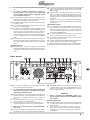
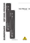
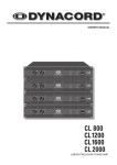
Rear panel
en
Rear panel control elements
(24) The unit’s fan is located here. Fan speed adjusts automatically to assure trouble-free operation.
$$
To prevent faulty operation, please make sure
that the unit is kept at a distance from other
appliances emanating heat.
(25) The SPEAKER OUTPUTS are high-quality professional
speaker connectors. The pin designation of the speaker is
pins 1+ and 1-. For details, refer to the section “Audio connectors”.
== In mono-bridged mode, connect one loudspeaker
to the middle jack MONO BRIDGE.
== In any other mode, connect one loudspeaker to
OUTPUT A/LOW and another to OUTPUT B/HIGH.
$$
Before you connect speakers to the BTX36000,
turn it off.
(26) The mains connection is established using a cable with an
IEC mains connector. This cable is delivered with the BTX.
(27) BREAKER (automated fuse). After eliminating the cause
of faulty operation, simply push the BREAKER back in and
power up the unit again. The BREAKER acts in place of
common disposable fuses.
Caution
$$
Before engaging the BREAKER switch, you
should power down the unit (POWER switch
set to OFF)!
EFFECTS LOOP jacks
(28) RETURN CHANNEL A/B: The unbalanced ¼" jacks are used
to route a mono or stereo signal from an external effects unit
back to the BTX.
== When using a stereo effects processor, route the
right part of the effect signal to RETURN CHANNEL
A and the left part of the effect signal to RETURN
CHANNEL B.
Control elements and connections
5
==
When using a mono effects processor, route the
effect signal only to RETURN CHANNEL A.
(29) SEND jack: To send an audio signal from the BTX to an
effects processor, use this ¼" TS jack.
INSERT CHANNEL section
channel A (and not of channel B) are used. Mono-bridged mode
is active when the button (21) glows.
Examples:
== Driving a single 8-Ohm loudspeaker.
== Driving a single 4-Ohm loudspeaker.
(30) POWER AMP INPUT: This unbalanced connector is used to
feed a mono signal to the amplifier A as well as one to the
amplifier B. This separates the internal signal path from the
amplifiers.
(31) PREAMP OUTPUT: This unbalanced connector is used to
tap the preamplifier signal and feed it to an external amplifier.
== When in BI-AMP mode, the low-frequency range
of the signal is sent through the PREAMP A/LOW
OUTPUT, while the signal’s high-frequency range is
sent through PREAMP B/HIGH OUTPUT.
== When in two-channel mode, connect the PREAMP
A/LOW OUTPUT with the amplifier’s right channel and the PREAMP B/HIGH OUTPUT with the left
channel.
BTX36000
(Mono bridge mode)
LINE OUTPUT features
(32) STEREO/MONO: This switch adjusts the routing of the
LINE signal between “wet” (with effects) and “dry” (without
effects). The switch is only effective when PRE/POST has
been pressed (“POST”) (33)!
== When in mono mode, LINE channel A has the
“wet” signal with all the external effects and LINE
channel B has the “dry” signal with the internal
signal path.
== When in stereo mode, both LINE outputs have the
“wet” signal with all external stereo effects.
(33) PRE/POST button: To select the type of signal you want to
send to a mixer/recording unit, use this button.
When this button is:
== pushed out (PRE EQ and effects), the BTX does not
apply any preamp features (TONE/EQ/EFFECTS) to
the audio signal.
== pushed in (POST EQ and effects), the BTX applies
all preamp features to the audio signal.
en
Mono-bridged mode
$$
(34) BAL: The internal signals of channels A and B are routed to
this balanced XLR connector. The type of signal depends
on the settings of the controls (32) and (33).
(35) BAL/UNBAL: The internal signals of channels A and B are
routed to these unbalanced ¼" TS connectors. You can also
connect these outputs to any balanced line inputs. The type
of signal depends on the settings of the controls (32) and
(33).
(36) TUNER OUTPUT jack: To connect the BTX36000 to
an electronic tuner, use this ¼" TS jack. There is also a
TUNER OUTPUT connector {3} on the unit’s front panel.
Both TUNER OUTPUT connectors may also be used to
hook up a stage monitor: the input signal is routed before
the MUTE function so that the signal is always fed to the
monitor speaker. This also means that it is not affected by
sound and level settings.
Caution
$$
$$
Running your amp in mono-bridged mode can
quickly result in excessive overdriving and
premature shutting down of the unit itself.
In the worst-case scenario, your loudspeakers may be damaged permanently. Therefore,
you should always make sure that the speakers you use can indeed handle the power load
fed into them.
$$
A voltage of up to 100 V RMS is present between the output connectors of the BUGERA.
Always implement appropriate safety precautions when connecting your speakers to avoid
the risk of electric shock.
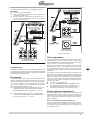
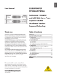
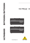
Applications
Mono-bridged mode
This mode is most commonly used on your BUGERA amplifier.
When running in mono-bridged mode, the voltage of both channels
is added up and fed into a single loudspeaker system. There is one
input and one output signal respectively, and only the controls of
6
The minimum load in mono-bridged mode is 4
Ohms. 2-Ohm loads should never be applied
when in mono-bridged mode.
Safety precautions for monobridged operation
(37) Connect the supplied footswitch to the FOOTSWITCH connector. Switch 1 activates and deactivates the graphic EQ.
Switch 2 turns the Effects Loop on and off.
Modes of operation
When the amp is overdriven for longer periods of time, the output signal may occasionally be muted for several seconds. In certain
situations, excessive overdriving may trigger
off the automated fuse. To avoid overdriving
the amp, please continually make sure that an
appropriate volume level is applied.
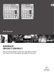
2-channel mode (stereo)
The 2-channel mode is a special feature of your BTX36000. Both
channels operate fully independently from one another. There is
Applications
always a separate input signal as well as a separate output signal.
2-channel mode is active when the button (21) is not lit (off).
Effects Processor
Examples:
== 2-channel (stereo) playback
== Two independent mono signals, such as instrument
signal and monitor mix
== Bi-amp operation, whereby bass frequencies are
run on channel A, and high frequencies on channel
B (see 4.2 “Bi-amping”).
BTX36000
(Bi-Amp Mode)
Stereo Effects Processor
ULTRABASS BA410
Full-Range Loudspeaker
BTX36000
(Stereo Mode)
ULTRABASS BA115
Bass Loudspeaker
Bi-amp operation
The compressor
ULTRABASS BA410
(Full-Range Loudspeaker)
A compressor is used to limit the dynamic range of a signal. Signal
peaks are lowered and soft signals are raised in volume, thus
reducing the difference between the highest and the lowest signal
levels. The result is a much more powerful sound.
2-channel mode (stereo)
Parallel mode
Parallel mode is identical to 2-channel mode, except that the inputs
of both channels are internally connected in parallel. Channels A
and B transmit the same signal which is useful for live applications
with speakers positioned far apart.
Bi-amping
The BTX’s active crossover is able to split up the signal into two
frequency bands. The mono signal’s low-frequency range (channel A) is separated from the high-frequency range (channel B).
The crossover frequency may be adjusted over the range of
50 Hz – 1 kHz, allowing you to select the frequency that corresponds to the speakers available to you:
== OUTPUT A: subwoofer, OUTPUT B: full-range loudspeaker (Example: EUROLIVE E1800X and ULTRABASS BB410) > crossover frequency: < 200 Hz
==
OUTPUT A, B: different full-range loudspeakers
(Example: ULTRABASS BB115 and ULTRABASS BB210)
> crossover frequency: > 300 Hz
Some playing techniques, such as slapping, lead to high-level
differences. In this case, a compressor can be used to make
the low-level dead notes clearly audible, which gives the bass
line even more groove. What is more, the sustain of long notes
is extended.
Compressors work best if provided with high input signals. If the
signal level is low, the effect will be activated only with high settings. If so, enabling the compressor can lead to extreme level
differences. If GAIN is high, the compressor comes in quite early.
In this case, you don’t need to turn up the COMPRESSION control
that far to achieve an effect. Experiment with it to find the best
setting for your needs!
== Turn on the compressor (7).
== Turn the COMPRESSION rotary knob (8) slowly to
the right to increase the level of compression.
== Use the ON (ACTIVE) switch to compare the compressed signal with the uncompressed signal.
About speaker impedance
The total impedance of the speakers that you connect to the
BTX36000 affects the power output. The minimum speaker impedance is 2 Ohms in stereo mode and 4 Ohms in mono-bridged
mode. The BTX36000 supplies the most power into the minimum
speaker impedance.
How to calculate the speaker impedance
When using more than one speaker and each connecting to another BTX speaker jack, the speakers are connected in parallel.
To calculate the resulting total impedance of the speakers, use
the following formula—
Applications
7
en
—where Z1, Z2 etc. are each the impedance of a single speaker
and Ztotal is the resulting impedance of all speakers.
For two speakers (Z1 and Z2), the formula reads as:
Z total =
Z1 ⋅ Z 2
Z1 + Z 2
Via the formula, you get a 4 Ω load with:
== one 4-Ohm speaker
== two 8-Ohm speakers
== one 8-Ohm speaker and two 16-Ohm speakers
$$
As the speaker impedance decreases, the
output power of the BTX increases. High output power can damage your speakers. As the
speaker impedance increases, the output
power of the BTX decreases.
Installation
Rack mounting
The BUGERA can be mounted on a 19" rack requiring 3 U of space.
Use 4 screws and washers to fix it to the front of the rack. Support
the rear side of the BTX, especially when often being transported.
Allow sufficient air circulation around the rack, particularly when
warm ventilation air of additional units enter the rack.
$$
The fan speed adjusts automatically and ensures safe operation. Never block ventilation
openings. Should internal temperature reach
extreme values, the unit will shut down automatically.
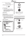
XLR connectors
Your BTX36000 is equipped with high-quality professional speaker
connectors, which ensure safe and trouble-free operation. These
connectors were especially developed for high-power loudspeakers. Once it is plugged in, it safely locks into its position and cannot
be accidentally disengaged. It prevents the occurrence of electrical
shock and ensures the correct polarity.
Audio connectors
en
The inputs of the BTX36000 as well as the EFFECTS LOOP and
INSERT CHANNEL are mono TS connectors.
Professional speaker connector
¼" TS connector
The Line outputs are balanced XLR and stereo TRS connectors.
8
Installation
$$
Should you register distractive signals such
as noise or hissing, we recommend separating the amp input from the signal source. This
way, you can quickly determine if the noise
originates from the equipment connected to
the amp. Make sure to turn the volume to a
minimum before turning it on (MASTER rotary
knob turned fully left) to avoid any damage
that may occur to your loudspeakers.
Footswitch connector
The footswitch connector is a ¼" TRS connector.
¼" TRS footswitch connector
en
Installation
9
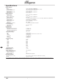
Specifications
Audio Inputs
INPUT
Input impedance
RETURN CHANNEL A/B
Input impedance
POWER AMP INPUT A/B
1 x ¼" mono jack, unbalanced
1 MΩ unbalanced (0 dB) / 80 kΩ unbalanced (–15 dB)
2 x ¼" mono jack, unbalanced
100 kΩ unbalanced
2 x ¼" mono jack, unbalanced
Input impedance
30 kΩ unbalanced
Output impedance
min. 2.2 kΩ
Audio Outputs
TUNER OUTPUT
EFFECTS LOOP SEND
Output impedance
LINE OUTPUT A/B
Output impedance
PREAMP OUTPUT A/B
Output impedance
Output level
Loudspeaker connectors
Load impedance
2 x ¼" mono jack, unbalanced
1 x ¼" mono jack, unbalanced
min. 2.2 kΩ
2 x XLR connector, balanced / 2 x ¼" mono jack, balanced or unbalanced
100 Ω balanced, 51 Ω unbalanced
2 x ¼" mono jack, unbalanced
min. 2 kΩ unbalanced
max. +21 dBu
3 x professional speaker connector
both channels driven
bridged mono
min. 2 Ω per channel
min. 4 Ω
Peak power, both channels driven
Peak power, both channels driven
Peak power, both channels driven
Peak power, bridged mono
2 x 1950 W / 2 Ω
2 x 1380 W / 4 Ω
2 x 800 W / 8 Ω
3800 W / 4 Ω
System data
Output power
Tone control range
BASS
MID
TREBLE
ULTRA LOW
BRIGHT
ULTRA HIGH
±12 dB @ 40 Hz
±15 dB @ 220 Hz / 450 Hz / 800 Hz / 1.6 kHz / 3 kHz
±15 dB @ 8 kHz
+2.5 dB @ 50 Hz
+6 dB @ 2 kHz
+6 dB @ 5 kHz
Graphic EQ range
en
33 Hz
80 Hz
150 Hz
300 Hz
600 Hz
900 Hz
2 kHz
5 kHz
8 kHz
Compression ratio
Signal-to-noise ratio
Power supply
Power consumption
Mains voltage / Breaker
100/120 V~ (50/60 Hz)
220/230 V~ (50/60 Hz)
Mains connector
Physical/weight
Dimensions (H x W x D)
Weight
±15 dB
±8 dB
±8 dB
±8 dB
±8 dB
±8 dB
±8 dB
±9 dB
±10 dB
10:1
75 dB
max. 3600 W
18 A
10 A
standard IEC receptacle
5.5" x 19.0" x 14.6" (140 mm x 485 mm x 370 mm)
43.9 lb. (19.9 kg)
We are constantly striving to maintain the highest professional standards. As a result of these efforts, modifications may be made from time to time to
existing products without prior notice. Specifications and appearance may differ from those listed or illustrated.
10
Specifications
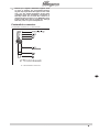
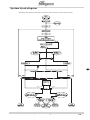
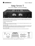
System block diagram
BTX36000 block diagram (Rectangles represent control elements, ovals represent jacks.)
en
OFF
ON
ON
OFF
BIAMP
System block diagram
11
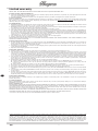
Limited warranty
SPECIAL NOTE: NO USER SERVICEABLE PARTS INSIDE. REFER SERVICING TO QUALIFIED PERSONNEL ONLY.
§ 1 Other warranty rights and national law
1. This limited warranty does not exclude or limit the buyer’s statutory rights provided by national law, in particular, any such rights against the seller that
arise from a legally effective purchase contract.
2. The limited warranty regulations mentioned herein are applicable unless they constitute an infringement of national warranty law.
§ 2 Online registration
Please do remember to register your new BUGERA equipment right after your purchase by visiting http://www.bugera-amps.com and kindly read the terms
and conditions of our limited warranty carefully. Registering your purchase and equipment with us helps us process your repair claims quicker and more
efficiently. Thank you for your cooperation!
§ 3 Limited Warranty
1. BEHRINGER warrants the mechanical and electronic components of this product to be free of defects in material and workmanship if used under normal
operating conditions for a period of one (1) year** from the original date of purchase.
2. BEHRINGER warrants valves (tubes) and meters contained in the product to be free of defects in material and workmanship if used under normal operating conditions for a period of 90 days from the original date of purchase.
3. This limited warranty is subject to the conditions, exclusions and limitations hereinafter set forth.
4. If the product shows any defects within the specified warranty period that are not excluded from this warranty as described under § 5, BEHRINGER will,
at its discretion, either replace the product by providing a new or reconditioned product or repair the product using suitable new or reconditioned parts.
In the case that other parts are used which constitute an improvement, BEHRINGER may, at its discretion, charge the customer for the additional cost
of these parts. In case BEHRINGER decides to replace the entire product, this warranty shall apply to the replacement product for the remaining initial
warranty period, i.e., one year** from the date of purchase of the initial product.
5. If the warranty claim proves to be justified, the product will be returned to the user freight prepaid.
6. Warranty claims other than those indicated above are expressly excluded.
PLEASE RETAIN YOUR SALES RECEIPT, AS IT IS YOUR PROOF OF PURCHASE COVERING YOUR LIMITED WARRANTY. THIS LIMITED WARRANTY IS VOID
WITHOUT SUCH PROOF OF PURCHASE.
§ 4 Return authorization number
1. To obtain warranty service, the buyer (or his authorized dealer) must call BEHRINGER as exclusive distributor of BUGERA products (see enclosed list)
during normal business hours BEFORE returning the product. All inquiries must be accompanied by a description of the problem. The buyer or his authorized dealer will receive a return authorization number.
2. Subsequently, the product must be returned in its original shipping carton, together with the return authorization number. The return shipment address
will be indicated by BEHRINGER.
3. Shipments without freight prepaid will not be accepted.
en
§ 5 Warranty regulations
1. Warranty services will be furnished only if the product is accompanied by a copy of the original retail dealer’s invoice.
2. If the product needs to be modified or adapted in order to comply with applicable technical or safety standards on a national or local level, in any country
which is not the country for which the product was originally developed and manufactured, this modification/adaptation shall not be considered a defect
in materials or workmanship. This limited warranty does not cover any such modification/adaptation, irrespective of whether it was carried out properly
or not. Under the terms of this limited warranty, BEHRINGER shall not be held responsible for any cost resulting from such a modification/adaptation.
3. Free inspections and maintenance/repair work are expressly excluded from this limited warranty, in particular, if caused by improper handling of the
product by the user. This also applies to defects caused by normal wear and tear, in particular, of faders, crossfaders, potentiometers, keys/buttons,
tubes, guitar strings, illuminants and similar parts.
4. Damage/defects caused by the following conditions are not covered by this limited warranty:
>> improper handling, neglect or failure to operate the unit in compliance with the instructions given in BEHRINGER user or service manuals.
>> connection or operation of the unit in any way that does not comply with the technical or safety regulations applicable in the country where the
product is used.
>> damage/defects caused by force majeure or any other condition that is beyond the control of BEHRINGER.
5. Any repair or service performed by any person or entity other than a BEHRINGER authorized service center is not covered by this limited warranty.
6. Any repair or opening of the unit carried out by unauthorized personnel (user included) will void this limited warranty.
7. Any exchange of the tubes/valves and associated biasing by any person or entity other than a BEHRINGER authorized service centre will void this limited
warranty.
8. If an inspection of the product by BEHRINGER shows that the defect in question is not covered by this limited warranty, the inspection costs are payable
by the customer.
9. Products which do not meet the terms of this limited warranty will be repaired exclusively at the buyer’s expense. BEHRINGER will inform the buyer of
any such circumstance. If the buyer fails to submit a written repair order within 6 weeks after notification, BEHRINGER will return the unit. Costs for
freight and packing will be invoiced separately C.O.D. When the buyer has sent in a written repair order, such costs will also be invoiced separately.
§ 6 Warranty transferability
This limited warranty is extended exclusively to the original buyer (customer of retail dealer) and is not transferable to anyone who may subsequently
purchase this product.
§ 7 Claim for damages
Failure of BEHRINGER to provide proper warranty service shall not entitle the buyer to claim (consequential) damages. In no event shall the liability of
BEHRINGER exceed the invoiced value of the product.
§ 8 U.S. Customers only
THE FOREGOING CONSTITUTES THE ONLY WARRANTY MADE BY BEHRINGER WITH RESPECT TO THE PRODUCT AND IS MADE EXPRESSLY IN LIEU OF ALL
OTHER WARRANTIES EXPRESS OR IMPLIED. Any implied warranties, including without limitation, any implied warranties of merchantability or fitness for
any particular purpose, imposed under state law are limited to the duration of this limited warranty. Some states do not allow limitations on how long an
implied warranty lasts, so the above limitations may not be applicable to you.
BEHRINGER ASSUMES NO LIABILITY FOR PROPERTY DAMAGE RESULTING FROM FAILURE OF THIS PRODUCT NOR ANY LOSS OF INCOME, SATISFACTION
OR DAMAGES ARISING FROM THE LOSS OF USE OF SAME DUE TO DEFECTS OR AVAILABILITY OF SAME DURING SERVICE.
**Customers in the European Union please contact BEHRINGER Germany Support for further details.
Technical specifications and appearance are subject to change without notice. The information contained herein is correct at the time of printing. RED
CHIP COMPANY LTD accepts no liability for any loss which may be suffered by any person who relies either wholly or in part upon any description, photograph or statement contained herein. Colors and specifications may vary slightly from product. Our Products are sold through authorized dealers only.
This manual is copyrighted. No part of this manual may be reproduced or transmitted in any form or by any means, electronic or mechanical, including photocopying and recording of any kind, for any purpose, without the express written permission of RED CHIP COMPANY LTD. BUGERA products
are distributed exclusively by the BEHRINGER Group of companies globally, and specifically by BEHRINGER Luxembourg Sàrl in the European Union.
ALL RIGHTS RESERVED. © 2009 RED CHIP COMPANY LTD. Trident Chambers, Wickhams Cay, P.O. Box 146, Road Town, Tortola, British Virgin Islands.
12
Limited warranty