1
Image Acquisition Toolbox™
User's Guide
R2015b
How to Contact MathWorks
Latest news:
www.mathworks.com
Sales and services:
www.mathworks.com/sales_and_services
User community:
www.mathworks.com/matlabcentral
Technical support:
www.mathworks.com/support/contact_us
Phone:
508-647-7000
The MathWorks, Inc.
3 Apple Hill Drive
Natick, MA 01760-2098
Image Acquisition Toolbox™ User's Guide
© COPYRIGHT 2003–2015 by The MathWorks, Inc.
The software described in this document is furnished under a license agreement. The software may be used
or copied only under the terms of the license agreement. No part of this manual may be photocopied or
reproduced in any form without prior written consent from The MathWorks, Inc.
FEDERAL ACQUISITION: This provision applies to all acquisitions of the Program and Documentation
by, for, or through the federal government of the United States. By accepting delivery of the Program
or Documentation, the government hereby agrees that this software or documentation qualifies as
commercial computer software or commercial computer software documentation as such terms are used
or defined in FAR 12.212, DFARS Part 227.72, and DFARS 252.227-7014. Accordingly, the terms and
conditions of this Agreement and only those rights specified in this Agreement, shall pertain to and
govern the use, modification, reproduction, release, performance, display, and disclosure of the Program
and Documentation by the federal government (or other entity acquiring for or through the federal
government) and shall supersede any conflicting contractual terms or conditions. If this License fails
to meet the government's needs or is inconsistent in any respect with federal procurement law, the
government agrees to return the Program and Documentation, unused, to The MathWorks, Inc.
Trademarks
MATLAB and Simulink are registered trademarks of The MathWorks, Inc. See
www.mathworks.com/trademarks for a list of additional trademarks. Other product or brand
names may be trademarks or registered trademarks of their respective holders.
Patents
MathWorks products are protected by one or more U.S. patents. Please see
www.mathworks.com/patents for more information.
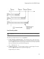
Revision History
March 2003
September 2003
June 2004
July 2004
October 2004
March 2005
March 2005
August 2005
September 2005
March 2006
September 2006
March 2007
September 2007
March 2008
October 2008
March 2009
September 2009
March 2010
September 2010
April 2011
September 2011
March 2012
September 2012
March 2013
September 2013
March 2014
October 2014
March 2015
September 2015
First printing
Online only
Online only
Online only
Online only
Online only
Second printing
Third printing
Online only
Fourth printing
Online only
Online only
Fifth printing
Online only
Online only
Online only
Online only
Online only
Online only
Online only
Online only
Online only
Online only
Online only
Online only
Online only
Online only
Online only
Online only
New for Version 1.0 (Release 13+)
Revised for Version 1.1 (Release 13SP1)
Revised for Version 1.5 (Release 14)
Revised for Version 1.6 (Release 14+)
Revised for Version 1.7 (Release 14SP1)
Revised for Version 1.8 (Release 14SP2)
Minor Revision for Version 1.8
Minor Revision for Version 1.8
Revised for Version 1.9 (Release 14SP3)
Revised for Version 1.10 (Release 2006a)
Revised for Version 2.0 (Release 2006b)
Revised for Version 2.1 (Release 2007a)
Revised for Version 3.0 (Release 2007b)
Revised for Version 3.1 (Release 2008a)
Revised for Version 3.2 (Release 2008b)
Revised for Version 3.3 (Release 2009a)
Revised for Version 3.4 (Release 2009b)
Revised for Version 3.5 (Release 2010a)
Revised for Version 4.0 (Release 2010b)
Revised for Version 4.1 (Release 2011a)
Revised for Version 4.2 (Release 2011b)
Revised for Version 4.3 (Release 2012a)
Revised for Version 4.4 (Release 2012b)
Revised for Version 4.5 (Release 2013a)
Revised for Version 4.6 (Release 2013b)
Revised for Version 4.7 (Release 2014a)
Revised for Version 4.8 (Release 2014b)
Revised for Version 4.9 (Release 2015a)
Revised for Version 4.10 (Release 2015b)
Contents
1
2
Getting Started
Image Acquisition Toolbox Product Description . . . . . . . . . .
Key Features . . . . . . . . . . . . . . . . . . . . . . . . . . . . . . . . . . . . .
1-2
1-2
Product Overview . . . . . . . . . . . . . . . . . . . . . . . . . . . . . . . . . . .
Introduction . . . . . . . . . . . . . . . . . . . . . . . . . . . . . . . . . . . . .
Installation and Configuration Notes . . . . . . . . . . . . . . . . . .
The Image Processing Toolbox Software Required to Use the
Image Acquisition Toolbox Software . . . . . . . . . . . . . . . . .
Related Products . . . . . . . . . . . . . . . . . . . . . . . . . . . . . . . . . .
Supported Hardware . . . . . . . . . . . . . . . . . . . . . . . . . . . . . . .
1-3
1-3
1-4
Image Acquisition Tool (GUI) . . . . . . . . . . . . . . . . . . . . . . . . .
1-6
Getting Started Doing Image Acquisition
Programmatically . . . . . . . . . . . . . . . . . . . . . . . . . . . . . . . . .
Overview . . . . . . . . . . . . . . . . . . . . . . . . . . . . . . . . . . . . . . . .
Step 1: Install Your Image Acquisition Device . . . . . . . . . . . .
Step 2: Retrieve Hardware Information . . . . . . . . . . . . . . . .
Step 3: Create a Video Input Object . . . . . . . . . . . . . . . . . .
Step 4: Preview the Video Stream (Optional) . . . . . . . . . . . .
Step 5: Configure Object Properties (Optional) . . . . . . . . . .
Step 6: Acquire Image Data . . . . . . . . . . . . . . . . . . . . . . . .
Step 7: Clean Up . . . . . . . . . . . . . . . . . . . . . . . . . . . . . . . . .
1-7
1-7
1-9
1-9
1-12
1-13
1-14
1-17
1-21
1-4
1-5
1-5
Introduction
Toolbox Components Overview . . . . . . . . . . . . . . . . . . . . . . . .
Introduction . . . . . . . . . . . . . . . . . . . . . . . . . . . . . . . . . . . . .
2-2
2-2
v
3
vi
Contents
Toolbox Components . . . . . . . . . . . . . . . . . . . . . . . . . . . . . . .
The Image Processing Toolbox Software Required to Use the
Image Acquisition Toolbox Software . . . . . . . . . . . . . . . . .
The Image Acquisition Tool (GUI) . . . . . . . . . . . . . . . . . . . . .
Supported Devices . . . . . . . . . . . . . . . . . . . . . . . . . . . . . . . . .
2-3
Setting Up Image Acquisition Hardware . . . . . . . . . . . . . . . .
Introduction . . . . . . . . . . . . . . . . . . . . . . . . . . . . . . . . . . . . .
Setting Up Frame Grabbers . . . . . . . . . . . . . . . . . . . . . . . . .
Setting Up Generic Windows Video Acquisition Devices . . . .
Setting Up DCAM Devices . . . . . . . . . . . . . . . . . . . . . . . . . .
Resetting Your Image Acquisition Hardware . . . . . . . . . . . . .
A Note About Frame Rates and Processing Speed . . . . . . . . .
2-7
2-7
2-7
2-8
2-8
2-8
2-8
Previewing Data . . . . . . . . . . . . . . . . . . . . . . . . . . . . . . . . . . .
Introduction . . . . . . . . . . . . . . . . . . . . . . . . . . . . . . . . . . . . .
Opening a Video Preview Window . . . . . . . . . . . . . . . . . . . .
Stopping the Preview Video Stream . . . . . . . . . . . . . . . . . .
Closing a Video Preview Window . . . . . . . . . . . . . . . . . . . .
Previewing Data in Custom GUIs . . . . . . . . . . . . . . . . . . . .
Performing Custom Processing of Previewed Data . . . . . . . .
2-10
2-10
2-11
2-12
2-13
2-13
2-15
2-4
2-5
2-5
Using the Image Acquisition Tool GUI
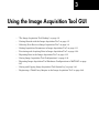
The Image Acquisition Tool Desktop . . . . . . . . . . . . . . . . . . .
Opening the Tool . . . . . . . . . . . . . . . . . . . . . . . . . . . . . . . . . .
Parts of the Desktop . . . . . . . . . . . . . . . . . . . . . . . . . . . . . . .
3-2
3-2
3-2
Getting Started with the Image Acquisition Tool . . . . . . . . .
3-5
Selecting Your Device in Image Acquisition Tool . . . . . . . . .
Selecting a Device and Format . . . . . . . . . . . . . . . . . . . . . . .
Adding New Hardware . . . . . . . . . . . . . . . . . . . . . . . . . . . .
Using a Camera File . . . . . . . . . . . . . . . . . . . . . . . . . . . . . .
3-8
3-8
3-10
3-10
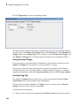
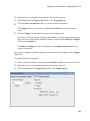
Setting Acquisition Parameters in Image Acquisition Tool
Using the Acquisition Parameters Pane . . . . . . . . . . . . . . .
Setting Frames Per Trigger . . . . . . . . . . . . . . . . . . . . . . . . .
Setting the Color Space . . . . . . . . . . . . . . . . . . . . . . . . . . . .
3-11
3-11
3-12
3-13
4
Setting Device-Specific Parameters . . . . . . . . . . . . . . . . . . .
Logging Your Data . . . . . . . . . . . . . . . . . . . . . . . . . . . . . . .
Setting Up Triggering . . . . . . . . . . . . . . . . . . . . . . . . . . . . .
Setting a Region of Interest . . . . . . . . . . . . . . . . . . . . . . . .
Restoring Default Parameters . . . . . . . . . . . . . . . . . . . . . . .
3-13
3-16
3-19
3-22
3-27
Previewing and Acquiring Data in Image Acquisition Tool
The Preview Window . . . . . . . . . . . . . . . . . . . . . . . . . . . . .
Previewing Data . . . . . . . . . . . . . . . . . . . . . . . . . . . . . . . . .
Acquiring Data . . . . . . . . . . . . . . . . . . . . . . . . . . . . . . . . . .
3-28
3-28
3-30
3-30
Exporting Data in the Image Acquisition Tool . . . . . . . . . .
3-35
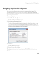
Saving Image Acquisition Tool Configurations . . . . . . . . . .
3-39
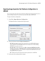
Exporting Image Acquisition Tool Hardware Configurations
to MATLAB . . . . . . . . . . . . . . . . . . . . . . . . . . . . . . . . . . . . . .
3-41
Saving and Copying Image Acquisition Tool Session Log .
About the Session Log . . . . . . . . . . . . . . . . . . . . . . . . . . . . .
Saving the Session Log . . . . . . . . . . . . . . . . . . . . . . . . . . . .
Copying the Session Log . . . . . . . . . . . . . . . . . . . . . . . . . . .
3-43
3-43
3-43
3-44
Registering a Third-Party Adaptor in the Image Acquisition
Tool . . . . . . . . . . . . . . . . . . . . . . . . . . . . . . . . . . . . . . . . . . . .
3-46
Image Acquisition Support Packages
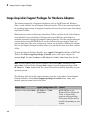
Image Acquisition Support Packages for Hardware
Adaptors . . . . . . . . . . . . . . . . . . . . . . . . . . . . . . . . . . . . . . . . .
4-2
Installing the Support Packages for Image Acquisition
Toolbox Adaptors . . . . . . . . . . . . . . . . . . . . . . . . . . . . . . . . . .
4-7
vii
5
6
Connecting to Hardware
Getting Hardware Information . . . . . . . . . . . . . . . . . . . . . . . .
Getting Hardware Information . . . . . . . . . . . . . . . . . . . . . . .
Determining the Device Adaptor Name . . . . . . . . . . . . . . . . .
Determining the Device ID . . . . . . . . . . . . . . . . . . . . . . . . . .
Determining Supported Video Formats . . . . . . . . . . . . . . . . .
5-2
5-2
5-2
5-3
5-5
Creating Image Acquisition Objects . . . . . . . . . . . . . . . . . . . .
Types of Objects . . . . . . . . . . . . . . . . . . . . . . . . . . . . . . . . . .
Video Input Objects . . . . . . . . . . . . . . . . . . . . . . . . . . . . . . . .
Video Source Objects . . . . . . . . . . . . . . . . . . . . . . . . . . . . . . .
Creating a Video Input Object . . . . . . . . . . . . . . . . . . . . . . .
Specifying the Video Format . . . . . . . . . . . . . . . . . . . . . . . .
Specifying the Selected Video Source Object . . . . . . . . . . . .
Getting Information About a Video Input Object . . . . . . . . .
5-8
5-8
5-8
5-8
5-9
5-11
5-13
5-14
Configuring Image Acquisition Object Properties . . . . . . .
About Image Acquisition Object Properties . . . . . . . . . . . . .
Viewing the Values of Object Properties . . . . . . . . . . . . . . .
Viewing the Value of a Particular Property . . . . . . . . . . . . .
Getting Information About Object Properties . . . . . . . . . . .
Setting the Value of an Object Property . . . . . . . . . . . . . . .
5-16
5-16
5-17
5-19
5-19
5-20
Starting and Stopping a Video Input Object . . . . . . . . . . . .
5-22
Deleting Image Acquisition Objects . . . . . . . . . . . . . . . . . . .
5-25
Saving Image Acquisition Objects . . . . . . . . . . . . . . . . . . . . .
Using the save Command . . . . . . . . . . . . . . . . . . . . . . . . . .
Using the obj2mfile Command . . . . . . . . . . . . . . . . . . . . . .
5-27
5-27
5-27
Image Acquisition Toolbox Properties . . . . . . . . . . . . . . . . .
5-28
Acquiring Image Data
Acquiring Image Data . . . . . . . . . . . . . . . . . . . . . . . . . . . . . . . .
viii
Contents
6-2
7
Data Logging . . . . . . . . . . . . . . . . . . . . . . . . . . . . . . . . . . . . . . .
Overview . . . . . . . . . . . . . . . . . . . . . . . . . . . . . . . . . . . . . . . .
Trigger Properties . . . . . . . . . . . . . . . . . . . . . . . . . . . . . . . . .
6-3
6-3
6-4
Setting the Values of Trigger Properties . . . . . . . . . . . . . . . .
About Trigger Properties . . . . . . . . . . . . . . . . . . . . . . . . . . . .
Specifying Trigger Type, Source, and Condition . . . . . . . . . .
6-6
6-6
6-6
Specifying the Trigger Type . . . . . . . . . . . . . . . . . . . . . . . . . .
Comparison of Trigger Types . . . . . . . . . . . . . . . . . . . . . . . .
Using an Immediate Trigger . . . . . . . . . . . . . . . . . . . . . . . . .
Using a Manual Trigger . . . . . . . . . . . . . . . . . . . . . . . . . . .
Using a Hardware Trigger . . . . . . . . . . . . . . . . . . . . . . . . .
Setting DCAM-Specific Trigger Modes . . . . . . . . . . . . . . . .
6-8
6-8
6-9
6-11
6-14
6-17
Controlling Logging Parameters . . . . . . . . . . . . . . . . . . . . . .
Data Logging . . . . . . . . . . . . . . . . . . . . . . . . . . . . . . . . . . . .
Specifying Logging Mode . . . . . . . . . . . . . . . . . . . . . . . . . . .
Specifying the Number of Frames to Log . . . . . . . . . . . . . . .
Determining How Much Data Has Been Logged . . . . . . . . .
Determining How Many Frames Are Available . . . . . . . . . .
Delaying Data Logging After a Trigger . . . . . . . . . . . . . . . .
Specifying Multiple Triggers . . . . . . . . . . . . . . . . . . . . . . . .
6-24
6-24
6-24
6-25
6-26
6-28
6-31
6-32
Waiting for an Acquisition to Finish . . . . . . . . . . . . . . . . . . .
Using the wait Function . . . . . . . . . . . . . . . . . . . . . . . . . . .
Blocking the Command Line Until an Acquisition Completes
6-34
6-34
6-35
Managing Memory Usage . . . . . . . . . . . . . . . . . . . . . . . . . . . .
Freeing Memory . . . . . . . . . . . . . . . . . . . . . . . . . . . . . . . . .
6-38
6-38
Logging Image Data to Disk . . . . . . . . . . . . . . . . . . . . . . . . . .
Logging Data to Disk Using VideoWriter . . . . . . . . . . . . . .
Logging Data to Disk Using VideoWriter . . . . . . . . . . . . . .
6-40
6-40
6-40
Working with Acquired Image Data
Image Acquisition Overview . . . . . . . . . . . . . . . . . . . . . . . . . .
7-2
ix
8
x
Contents
Bringing Image Data into the MATLAB Workspace . . . . . . .
Overview . . . . . . . . . . . . . . . . . . . . . . . . . . . . . . . . . . . . . . . .
Moving Multiple Frames into the Workspace . . . . . . . . . . . .
Viewing Frames in the Memory Buffer . . . . . . . . . . . . . . . . .
Bringing a Single Frame into the Workspace . . . . . . . . . . .
7-3
7-3
7-4
7-6
7-10
Working with Image Data in MATLAB Workspace . . . . . . .
Understanding Image Data . . . . . . . . . . . . . . . . . . . . . . . . .
Determining the Dimensions of Image Data . . . . . . . . . . . .
Determining the Data Type of Image Frames . . . . . . . . . . .
Specifying the Color Space . . . . . . . . . . . . . . . . . . . . . . . . .
Viewing Acquired Data . . . . . . . . . . . . . . . . . . . . . . . . . . . .
7-11
7-11
7-12
7-15
7-16
7-22
Retrieving Timing Information . . . . . . . . . . . . . . . . . . . . . . .
Introduction . . . . . . . . . . . . . . . . . . . . . . . . . . . . . . . . . . . . .
Determining When a Trigger Executed . . . . . . . . . . . . . . . .
Determining When a Frame Was Acquired . . . . . . . . . . . . .
Determining the Frame Delay Duration . . . . . . . . . . . . . . .
7-23
7-23
7-23
7-24
7-25
Using Events and Callbacks
Using Events and Callbacks . . . . . . . . . . . . . . . . . . . . . . . . . . .
8-2
Using the Default Callback Function . . . . . . . . . . . . . . . . . . .
8-3
Event Types . . . . . . . . . . . . . . . . . . . . . . . . . . . . . . . . . . . . . . . .
8-5
Retrieving Event Information . . . . . . . . . . . . . . . . . . . . . . . . .
Introduction . . . . . . . . . . . . . . . . . . . . . . . . . . . . . . . . . . . . .
Event Structures . . . . . . . . . . . . . . . . . . . . . . . . . . . . . . . . . .
Accessing Data in the Event Log . . . . . . . . . . . . . . . . . . . . .
8-8
8-8
8-8
8-10
Creating and Executing Callback Functions . . . . . . . . . . . .
Introduction . . . . . . . . . . . . . . . . . . . . . . . . . . . . . . . . . . . . .
Creating Callback Functions . . . . . . . . . . . . . . . . . . . . . . . .
Specifying Callback Functions . . . . . . . . . . . . . . . . . . . . . . .
Viewing a Sample Frame . . . . . . . . . . . . . . . . . . . . . . . . . .
8-12
8-12
8-12
8-14
8-16
9
10
Using the From Video Device Block in Simulink
Simulink Image Acquisition Overview . . . . . . . . . . . . . . . . . .
9-2
Opening the Image Acquisition Toolbox Block Library . . . .
Using the imaqlib Command . . . . . . . . . . . . . . . . . . . . . . . . .
Using the Simulink Library Browser . . . . . . . . . . . . . . . . . .
9-3
9-3
9-4
Using Code Generation . . . . . . . . . . . . . . . . . . . . . . . . . . . . . . .
9-5
Saving Video Data to a File . . . . . . . . . . . . . . . . . . . . . . . . . . .
Introduction . . . . . . . . . . . . . . . . . . . . . . . . . . . . . . . . . . . . .
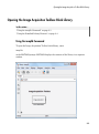
Step 1: Open the Image Acquisition Toolbox Library . . . . . . .
Step 2: Open a Model or Create a New Model . . . . . . . . . . . .
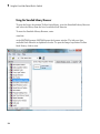
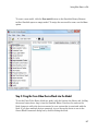
Step 3: Drag the From Video Device Block into the Model . . .
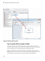
Step 4: Drag Other Blocks to Complete the Model . . . . . . . . .
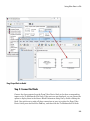
Step 5: Connect the Blocks . . . . . . . . . . . . . . . . . . . . . . . . . .
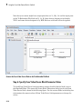
Step 6: Specify From Video Device Block Parameter Values .
Step 7: Run the Simulation . . . . . . . . . . . . . . . . . . . . . . . . .
9-6
9-6
9-6
9-6
9-7
9-8
9-9
9-10
9-11
Configuring GigE Vision Devices
Types of Setups . . . . . . . . . . . . . . . . . . . . . . . . . . . . . . . . . . . .
10-2
Network Hardware Configuration Notes . . . . . . . . . . . . . . .
10-3
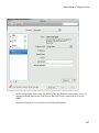
Network Adaptor Configuration Notes . . . . . . . . . . . . . . . . .
Windows Configuration . . . . . . . . . . . . . . . . . . . . . . . . . . . .
Linux Configuration . . . . . . . . . . . . . . . . . . . . . . . . . . . . . .
Mac Configuration . . . . . . . . . . . . . . . . . . . . . . . . . . . . . . . .
10-4
10-4
10-5
10-6
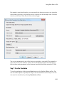
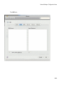
Software Configuration . . . . . . . . . . . . . . . . . . . . . . . . . . . . .
10-11
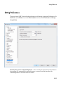
Setting Preferences . . . . . . . . . . . . . . . . . . . . . . . . . . . . . . . .
10-13
Troubleshooting . . . . . . . . . . . . . . . . . . . . . . . . . . . . . . . . . . .
10-15
xi
11
12
xii
Contents
Using the GigE Vision Interface
GigE Vision Acquisition: gigecam Object vs. videoinput
Object . . . . . . . . . . . . . . . . . . . . . . . . . . . . . . . . . . . . . . . . . . .
11-2
Connect to GigE Vision Cameras . . . . . . . . . . . . . . . . . . . . . .
11-3
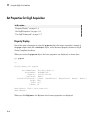
Set Properties for GigE Acquisition . . . . . . . . . . . . . . . . . . .
Property Display . . . . . . . . . . . . . . . . . . . . . . . . . . . . . . . . .
Set GigE Properties . . . . . . . . . . . . . . . . . . . . . . . . . . . . . .
Use GigE Commands . . . . . . . . . . . . . . . . . . . . . . . . . . . . .
11-4
11-4
11-6
11-7
Acquire Images from GigE Vision Cameras . . . . . . . . . . . . .
Create the gigecam Object . . . . . . . . . . . . . . . . . . . . . . . . .
Acquire One Image Frame from a GigE Camera . . . . . . . .
11-9
11-9
11-12
Using the Kinect for Windows Adaptor
Important Information About the Kinect Adaptor . . . . . . .
12-2
Data Streams Returned by the Kinect . . . . . . . . . . . . . . . . .
12-4
Detecting the Kinect Devices . . . . . . . . . . . . . . . . . . . . . . . . .
12-7
Acquiring Image and Skeletal Data Using Kinect . . . . . . . .
12-9
Acquiring from Color and Depth Devices Simultaneously
12-23
Using Skeleton Viewer for Kinect Skeletal Data . . . . . . . .
12-24
Installing the Kinect for Windows Sensor Support
Package . . . . . . . . . . . . . . . . . . . . . . . . . . . . . . . . . . . . . . . .
12-27
13
14
Using the Matrox Interface
Matrox Acquisition – matroxcam Object vs videoinput
Object . . . . . . . . . . . . . . . . . . . . . . . . . . . . . . . . . . . . . . . . . . .
13-2
Connect to Matrox Frame Grabbers . . . . . . . . . . . . . . . . . . .
13-3
Set Properties for Matrox Acquisition . . . . . . . . . . . . . . . . .
13-4
Acquire Images from Matrox Frame Grabbers . . . . . . . . . .
Create the matroxcam Object . . . . . . . . . . . . . . . . . . . . . . .
Acquire One Image Frame from a Matrox Frame Grabber . .
13-6
13-6
13-7
Using the VideoDevice System Object
VideoDevice System Object Overview . . . . . . . . . . . . . . . . .
14-2
Creating the VideoDevice System Object . . . . . . . . . . . . . . .
14-3
Using VideoDevice System Object to Acquire Frames . . . .
Kinect for Windows Metadata . . . . . . . . . . . . . . . . . . . . . . .
14-5
14-7
Using Properties on a VideoDevice System Object . . . . . .
14-10
Code Generation with VideoDevice System Object . . . . . .
Using the codegen Function . . . . . . . . . . . . . . . . . . . . . .
Shared Library Dependencies . . . . . . . . . . . . . . . . . . . . . .
Usage Rules for System Objects in Generated MATLAB
Code . . . . . . . . . . . . . . . . . . . . . . . . . . . . . . . . . . . . . . .
Limitations on Using System Objects in Generated MATLAB
Code . . . . . . . . . . . . . . . . . . . . . . . . . . . . . . . . . . . . . . .
14-14
14-14
14-14
14-15
14-16
xiii
15
Adding Support for Additional Hardware
Support for Additional Hardware . . . . . . . . . . . . . . . . . . . . .
16
xiv
Contents
15-2
Troubleshooting
Troubleshooting Overview . . . . . . . . . . . . . . . . . . . . . . . . . . .
16-2
DALSA Coreco IFC Hardware . . . . . . . . . . . . . . . . . . . . . . . .
Troubleshooting DALSA Coreco IFC Devices . . . . . . . . . . . .
Determining the Driver Version for DALSA Coreco IFC
Devices . . . . . . . . . . . . . . . . . . . . . . . . . . . . . . . . . . . . . .
16-3
16-3
DALSA Coreco Sapera Hardware . . . . . . . . . . . . . . . . . . . . .
Troubleshooting DALSA Coreco Sapera Devices . . . . . . . . .
Determining the Driver Version for DALSA Coreco Sapera
Devices . . . . . . . . . . . . . . . . . . . . . . . . . . . . . . . . . . . . . .
16-5
16-5
Data Translation Hardware . . . . . . . . . . . . . . . . . . . . . . . . . .
16-7
DCAM IEEE 1394 (FireWire) Hardware on Windows . . . . .
Troubleshooting DCAM IEEE 1394 Hardware on Windows .
Installing the CMU DCAM Driver on Windows . . . . . . . . .
Running the CMU Camera Demo Application on Windows
16-9
16-9
16-10
16-11
Hamamatsu Hardware . . . . . . . . . . . . . . . . . . . . . . . . . . . . .
16-15
Matrox Hardware . . . . . . . . . . . . . . . . . . . . . . . . . . . . . . . . . .
Troubleshooting Matrox Devices . . . . . . . . . . . . . . . . . . . .
Determining the Driver Version for Matrox Devices . . . . .
16-16
16-16
16-17
QImaging Hardware . . . . . . . . . . . . . . . . . . . . . . . . . . . . . . .
Troubleshooting QImaging Devices . . . . . . . . . . . . . . . . . .
Determining the Driver Version for QImaging Devices . . .
16-18
16-18
16-19
National Instruments Hardware . . . . . . . . . . . . . . . . . . . . .
Troubleshooting National Instruments Devices . . . . . . . . .
16-20
16-20
16-4
16-6
Determining the Driver Version for National Instruments
Devices . . . . . . . . . . . . . . . . . . . . . . . . . . . . . . . . . . . . .
16-21
Point Grey Hardware . . . . . . . . . . . . . . . . . . . . . . . . . . . . . .
Troubleshooting Point Grey Devices . . . . . . . . . . . . . . . . .
Determining the Driver Version for Point Grey Devices . . .
16-22
16-22
16-23
Kinect for Windows Hardware . . . . . . . . . . . . . . . . . . . . . . .
16-24
GigE Vision Hardware . . . . . . . . . . . . . . . . . . . . . . . . . . . . .
Troubleshooting GigE Vision Devices on Windows . . . . . . .
Troubleshooting GigE Vision Devices on Linux . . . . . . . . .
Troubleshooting GigE Vision Devices on Mac . . . . . . . . . .
16-26
16-26
16-29
16-31
GenICam GenTL Hardware . . . . . . . . . . . . . . . . . . . . . . . . .
Troubleshooting GenICam GenTL Hardware . . . . . . . . . . .
16-34
16-34
Windows Video Hardware . . . . . . . . . . . . . . . . . . . . . . . . . .
Troubleshooting Windows Video Devices . . . . . . . . . . . . . .
Determining the Microsoft DirectX Version . . . . . . . . . . . .
16-36
16-36
16-37
Linux Video Hardware . . . . . . . . . . . . . . . . . . . . . . . . . . . . .
Troubleshooting Linux Video Devices . . . . . . . . . . . . . . . .
16-39
16-39
Linux DCAM IEEE 1394 Hardware . . . . . . . . . . . . . . . . . . .
Troubleshooting Linux DCAM Devices . . . . . . . . . . . . . . .
16-41
16-41
Macintosh Video Hardware . . . . . . . . . . . . . . . . . . . . . . . . .
Troubleshooting Macintosh Video Devices . . . . . . . . . . . . .
16-42
16-42
Macintosh DCAM IEEE 1394 Hardware . . . . . . . . . . . . . . .
Troubleshooting Macintosh DCAM Devices . . . . . . . . . . . .
16-43
16-43
Video Preview Window Troubleshooting . . . . . . . . . . . . . .
16-44
Contacting MathWorks and Using the imaqsupport
Function . . . . . . . . . . . . . . . . . . . . . . . . . . . . . . . . . . . . . . .
16-45
xv
17
18
19
xvi
Contents
Functions — Alphabetical List
Properties — Alphabetical List
Block Reference
1
Getting Started
The best way to learn about Image Acquisition Toolbox capabilities is to look at a simple
example. This chapter introduces the toolbox and illustrates the basic steps to create an
image acquisition application by implementing a simple motion detection application.
The example cross-references other sections that provide more details about relevant
concepts.
• “Image Acquisition Toolbox Product Description” on page 1-2
• “Product Overview” on page 1-3
• “Image Acquisition Tool (GUI)” on page 1-6
• “Getting Started Doing Image Acquisition Programmatically” on page 1-7
1
Getting Started
Image Acquisition Toolbox Product Description
Acquire images and video from industry-standard hardware
Image Acquisition Toolbox enables you to acquire images and video from cameras
and frame grabbers directly into MATLAB® and Simulink®. You can detect hardware
automatically, and configure hardware properties. Advanced workflows let you
trigger acquisition while processing in-the-loop, perform background acquisition, and
synchronize sampling across several multimodal devices. With support for multiple
hardware vendors and industry standards, you can use imaging devices, ranging from
inexpensive Web cameras to high-end scientific and industrial devices that meet lowlight, high-speed, and other challenging requirements.
Key Features
• Support for industry standards, including DCAM, Camera Link®, and GigE Vision
• Support for common OS interfaces for webcams, including DirectShow®, QuickTime,
and Video4Linux2
• Support for a range of industrial and scientific hardware vendors
• Multiple acquisition modes and buffer management options
• Synchronization of multimodal acquisition devices with hardware triggering
• Image Acquisition app for rapid hardware configuration, image acquisition, and live
video previewing
• Support for C code generation in Simulink
1-2
Product Overview
Product Overview
In this section...
“Introduction” on page 1-3
“Installation and Configuration Notes” on page 1-4
“The Image Processing Toolbox Software Required to Use the Image Acquisition Toolbox
Software” on page 1-4
“Related Products” on page 1-5
“Supported Hardware” on page 1-5
Introduction
The Image Acquisition Toolbox software is a collection of functions that extend the
capability of the MATLAB numeric computing environment. The toolbox supports a wide
range of image acquisition operations, including:
• Acquiring images through many types of image acquisition devices, from professional
grade frame grabbers to USB-based webcams
• Viewing a preview of the live video stream
• Triggering acquisitions (includes external hardware triggers)
• Configuring callback functions that execute when certain events occur
• Bringing the image data into the MATLAB workspace
Many of the toolbox functions are MATLAB files. You can view the MATLAB code for
these functions using this statement:
type function_name
You can extend Image Acquisition Toolbox capabilities by writing your own MATLAB
files, or by using the toolbox in combination with other toolboxes, such as the Image
Processing Toolbox™ software and the Data Acquisition Toolbox™ software.
The Image Acquisition Toolbox software also includes a Simulink block, called From
Video Device, that you can use to bring live video data into a model.
1-3
1
Getting Started
Installation and Configuration Notes
To determine if the Image Acquisition Toolbox software is installed on your system, type
this command at the MATLAB prompt:
ver
When you enter this command, MATLAB displays information about the version of
MATLAB you are running, including a list of all toolboxes installed on your system and
their version numbers.
For information about installing the toolbox, see the MATLAB Installation Guide.
For the most up-to-date information about system requirements, see the system
requirements page, available in the products area at the MathWorks Web site
(www.mathworks.com).
Note: With previous versions of the Image Acquisition Toolbox, the files for all of the
adaptors were included in your installation. Starting with version R2014a, each adaptor
is available separately through the Support Package Installer. In order to use the Image
Acquisition Toolbox, you must install the adaptor that your camera uses. See “Image
Acquisition Support Packages for Hardware Adaptors” on page 4-2 for information
about installing the adaptors.
The Image Processing Toolbox Software Required to Use the Image
Acquisition Toolbox Software
The Image Acquisition Toolbox product, including the Image Acquisition Tool, now
requires you to have a license for the Image Processing Toolbox product starting in
R2008b.
If you already have the Image Processing Toolbox product, you do not need to do
anything.
If you do not have the Image Processing Toolbox product, the Image Acquisition
Toolbox software R2008a and earlier will continue to work. If you want to use R2008b
or future releases, and you have a current active license for the Image Acquisition
Toolbox software, you can download the Image Processing Toolbox product for free. New
customers will need to purchase both products to use the Image Acquisition Toolbox
product.
1-4
Product Overview
If you have any questions, please contact MathWorks customer service.
Related Products
MathWorks provides several products that are relevant to the kinds of tasks you can
perform with the Image Acquisition Toolbox software and that extend the capabilities
of MATLAB. For information about these related products, see www.mathworks.com/
products/imaq/related.html.
Supported Hardware
The list of hardware that the Image Acquisition Toolbox software supports can change
in each release, since hardware support is frequently added. The MathWorks Web site is
the best place to check for the most up to date listing.
To see the full list of hardware that the toolbox supports, visit the Image Acquisition
Toolbox product page at the MathWorks Web site www.mathworks.com/products/imaq
and click the Supported Hardware link.
1-5
1
Getting Started
Image Acquisition Tool (GUI)
The functionality of the Image Acquisition Toolbox software is available in a desktop
application. You connect directly to your hardware in the tool and can set acquisition
parameters, and preview and acquire image data. You can log the data to MATLAB in
several formats, and also generate a VideoWriter file, right from the tool.
To open the tool, type imaqtool at the MATLAB command line, or select Image
Acquisition on the Apps tab in MATLAB. The tool has extensive Help in the desktop.
As you click in different panes of the user interface, the relevant Help appears in the
Image Acquisition Tool Help pane.
Most of the User's Guide describes performing tasks using the toolbox via the MATLAB
command line. To learn how to use the desktop tool, see “Getting Started with the Image
Acquisition Tool” on page 3-5.
1-6
Getting Started Doing Image Acquisition Programmatically
Getting Started Doing Image Acquisition Programmatically
In this section...
“Overview” on page 1-7
“Step 1: Install Your Image Acquisition Device” on page 1-9
“Step 2: Retrieve Hardware Information” on page 1-9
“Step 3: Create a Video Input Object” on page 1-12
“Step 4: Preview the Video Stream (Optional)” on page 1-13
“Step 5: Configure Object Properties (Optional)” on page 1-14
“Step 6: Acquire Image Data” on page 1-17
“Step 7: Clean Up” on page 1-21
Overview
This section illustrates the basic steps required to create an image acquisition application
by implementing a simple motion detection application. The application detects
movement in a scene by performing a pixel-to-pixel comparison in pairs of incoming
image frames. If nothing moves in the scene, pixel values remain the same in each
frame. When something moves in the image, the application displays the pixels that have
changed values.
The example highlights how you can use the Image Acquisition Toolbox software to
create a working image acquisition application with only a few lines of code.
Note To run the sample code in this example, you must have an image acquisition device
connected to your system. The device can be a professional grade image acquisition
device, such as a frame grabber, or a generic Microsoft® Windows® image acquisition
device, such as a webcam. The code can be used with various types of devices with only
minor changes.
1-7
1
Getting Started
Note: With previous versions of the Image Acquisition Toolbox, the files for all of the
adaptors were included in your installation. Starting with version R2014a, each adaptor
is available separately through the Support Package Installer. In order to use the Image
Acquisition Toolbox, you must install the adaptor that your camera uses. See “Image
Acquisition Support Packages for Hardware Adaptors” on page 4-2 for information
about installing the adaptors.
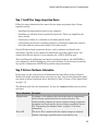
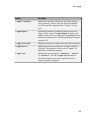
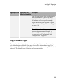
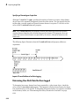
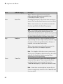
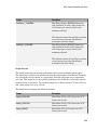
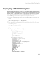
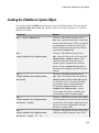
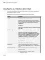
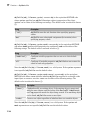
To use the Image Acquisition Toolbox software to acquire image data, you must perform
the following basic steps.
Step
Description
Step 1:
Install and configure your image acquisition device
Step 2:
Retrieve information that uniquely identifies your image acquisition
device to the Image Acquisition Toolbox software
Step 3:
Create a video input object
Step 4:
Preview the video stream (Optional)
Step 5:
Configure image acquisition object properties (Optional)
Step 6:
Acquire image data
Step 7:
Clean up
The Image Processing Toolbox Software Required to Use the Image Acquisition
Toolbox Software
The Image Acquisition Toolbox product, including the Image Acquisition Tool, requires
you to have a license for the Image Processing Toolbox product starting in R2008b.
If you already have the Image Processing Toolbox product, you do not need to do
anything.
If you do not have the Image Processing Toolbox product, the Image Acquisition
Toolbox software R2008a and earlier will continue to work. If you want to use R2008b
or future releases, and you have a current active license for the Image Acquisition
Toolbox software, you can download the Image Processing Toolbox product for free. New
customers will need to purchase both products to use the Image Acquisition Toolbox
product.
If you have any questions, please contact MathWorks customer service.
1-8
Getting Started Doing Image Acquisition Programmatically
Step 1: Install Your Image Acquisition Device
Follow the setup instructions that come with your image acquisition device. Setup
typically involves:
• Installing the frame grabber board in your computer.
• Installing any software drivers required by the device. These are supplied by the
device vendor.
• Connecting a camera to a connector on the frame grabber board.
• Verifying that the camera is working properly by running the application software
that came with the camera and viewing a live video stream.
Generic Windows image acquisition devices, such as webcams and digital video
camcorders, typically do not require the installation of a frame grabber board. You
connect these devices directly to your computer via a USB or FireWire port.
After installing and configuring your image acquisition hardware, start MATLAB on
your computer by double-clicking the icon on your desktop. You do not need to perform
any special configuration of MATLAB to perform image acquisition.
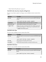
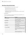
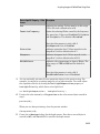
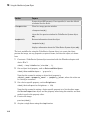
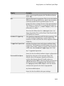
Step 2: Retrieve Hardware Information
In this step, you get several pieces of information that the toolbox needs to uniquely
identify the image acquisition device you want to access. You use this information when
you create an image acquisition object, described in “Step 3: Create a Video Input Object”
on page 1-12.
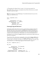
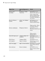
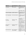
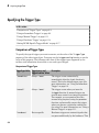
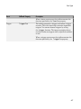
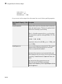
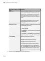
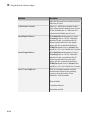
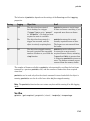
The following table lists this information. You use the imaqhwinfo function to retrieve
each item.
Device Information
Description
Adaptor name
An adaptor is the software that the toolbox uses to communicate
with an image acquisition device via its device driver. The
toolbox includes adaptors for certain vendors of image acquisition
equipment and for particular classes of image acquisition devices.
See “Determining the Adaptor Name” on page 1-10 for more
information.
Device ID
The device ID is a number that the adaptor assigns to uniquely
identify each image acquisition device with which it can
1-9
1
Getting Started
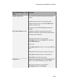
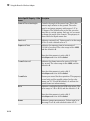
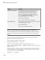
Device Information
Description
communicate. See “Determining the Device ID” on page 1-10 for
more information.
Note: Specifying the device ID is optional; the toolbox uses the first
available device ID as the default.
Video format
The video format specifies the image resolution (width and height)
and other aspects of the video stream. Image acquisition devices
typically support multiple video formats. See “Determining the
Supported Video Formats” on page 1-11 for more information.
Note: Specifying the video format is optional; the toolbox uses one of
the supported formats as the default.
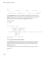
Determining the Adaptor Name
To determine the name of the adaptor, enter the imaqhwinfo function at the MATLAB
prompt without any arguments.
imaqhwinfo
ans =
InstalledAdaptors:
MATLABVersion:
ToolboxName:
ToolboxVersion:
{'dcam' 'winvideo'}
'7.4 (R2007a)'
'Image Acquisition Toolbox'
'2.1 (R2007a)'
In the data returned by imaqhwinfo, the InstalledAdaptors field lists the adaptors
that are available on your computer. In this example, imaqhwinfo found two adaptors
available on the computer: 'dcam' and 'winvideo'. The listing on your computer
might contain only one adaptor name. Select the adaptor name that provides access
to your image acquisition device. For more information, see “Determining the Device
Adaptor Name” on page 5-2.
Determining the Device ID
To find the device ID of a particular image acquisition device, enter the imaqhwinfo
function at the MATLAB prompt, specifying the name of the adaptor as the only
argument. (You found the adaptor name in the first call to imaqhwinfo, described
1-10
Getting Started Doing Image Acquisition Programmatically
in “Determining the Adaptor Name” on page 1-10.) In the data returned, the
DeviceIDs field is a cell array containing the device IDs of all the devices accessible
through the specified adaptor.
Note This example uses the DCAM adaptor. You should substitute the name of the
adaptor you would like to use.
info = imaqhwinfo('dcam')
info =
AdaptorDllName:
AdaptorDllVersion:
AdaptorName:
DeviceIDs:
DeviceInfo:
[1x77 char]
'2.1 (R2007a)'
'dcam'
{[1]}
[1x1 struct]
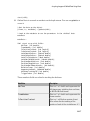
Determining the Supported Video Formats
To determine which video formats an image acquisition device supports, look in the
DeviceInfo field of the data returned by imaqhwinfo. The DeviceInfo field is a
structure array where each structure provides information about a particular device.
To view the device information for a particular device, you can use the device ID as a
reference into the structure array. Alternatively, you can view the information for a
particular device by calling the imaqhwinfo function, specifying the adaptor name and
device ID as arguments.
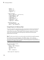
To get the list of the video formats supported by a device, look at SupportedFormats
field in the device information structure. The SupportedFormats field is a cell array
of strings where each string is the name of a video format supported by the device. For
more information, see “Determining Supported Video Formats” on page 5-5.
dev_info = imaqhwinfo('dcam',1)
dev_info =
DefaultFormat:
DeviceFileSupported:
DeviceName:
DeviceID:
VideoInputConstructor:
VideoDeviceConstructor:
'F7_Y8_1024x768'
0
'XCD-X700 1.05'
1
'videoinput('dcam', 1)'
'imaq.VideoDevice('dcam', 1)'
1-11
1
Getting Started
SupportedFormats: {'F7_Y8_1024x768'
'Y8_1024x768'}
Step 3: Create a Video Input Object
In this step you create the video input object that the toolbox uses to represent the
connection between MATLAB and an image acquisition device. Using the properties
of a video input object, you can control many aspects of the image acquisition process.
For more information about image acquisition objects, see “Creating Image Acquisition
Objects” on page 5-8.
To create a video input object, use the videoinput function at the MATLAB prompt.
The DeviceInfo structure returned by the imaqhwinfo function contains the default
videoinput function syntax for a device in the VideoInputConstructor field. For
more information the device information structure, see “Determining the Supported
Video Formats” on page 1-11.
The following example creates a video input object for the DCAM adaptor. Substitute the
adaptor name of the image acquisition device available on your system.
vid = videoinput('dcam',1,'Y8_1024x768')
The videoinput function accepts three arguments: the adaptor name, device ID, and
video format. You retrieved this information in step 2. The adaptor name is the only
required argument; the videoinput function can use defaults for the device ID and
video format. To determine the default video format, look at the DefaultFormat field
in the device information structure. See “Determining the Supported Video Formats” on
page 1-11 for more information.
Instead of specifying the video format, you can optionally specify the name of a device
configuration file, also known as a camera file. Device configuration files are typically
supplied by frame grabber vendors. These files contain all the required configuration
settings to use a particular camera with the device. See “Using Device Configuration
Files (Camera Files)” on page 5-12 for more information.
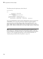
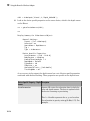
Viewing the Video Input Object Summary
To view a summary of the video input object you just created, enter the variable name
vid at the MATLAB command prompt. The summary information displayed shows many
of the characteristics of the object, such as the number of frames that will be captured
with each trigger, the trigger type, and the current state of the object. You can use video
input object properties to control many of these characteristics. See “Step 5: Configure
Object Properties (Optional)” on page 1-14 for more information.
1-12
Getting Started Doing Image Acquisition Programmatically
vid
Summary of Video Input Object Using 'XCD-X700
Acquisition Source(s):
Acquisition Parameters:
Trigger Parameters:
Status:
1.05'.
input1 is available.
'input1' is the current selected source.
10 frames per trigger using the selected source.
'Y8_1024x768' video data to be logged upon START.
Grabbing first of every 1 frame(s).
Log data to 'memory' on trigger.
1 'immediate' trigger(s) on START.
Waiting for START.
0 frames acquired since starting.
0 frames available for GETDATA.
Step 4: Preview the Video Stream (Optional)
After you create the video input object, MATLAB is able to access the image acquisition
device and is ready to acquire data. However, before you begin, you might want to see a
preview of the video stream to make sure that the image is satisfactory. For example, you
might want to change the position of the camera, change the lighting, correct the focus,
or make some other change to your image acquisition setup.
Note This step is optional at this point in the procedure because you can preview a video
stream at any time after you create a video input object.
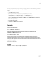
To preview the video stream in this example, enter the preview function at the
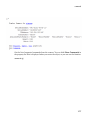
MATLAB prompt, specifying the video input object created in step 3 as an argument.
preview(vid)
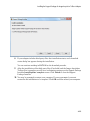
The preview function opens a Video Preview figure window on your screen containing
the live video stream. To stop the stream of live video, you can call the stoppreview
function. To restart the preview stream, call preview again on the same video input
object.
While a preview window is open, the video input object sets the value of the Previewing
property to 'on'. If you change characteristics of the image by setting image acquisition
object properties, the image displayed in the preview window reflects the change.
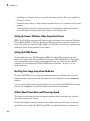
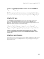
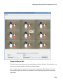
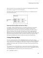
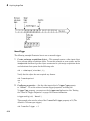
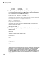
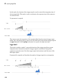
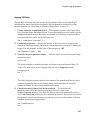
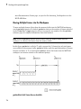
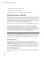
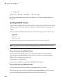
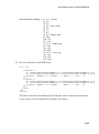
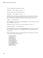
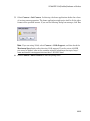
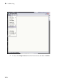
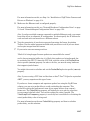
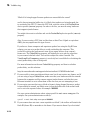
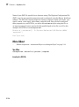
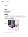
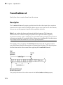
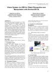
The following figure shows the Video Preview window for the example.
1-13
1
Getting Started
Video Preview Window
To close the Video Preview window, click the Close button in the title bar or use the
closepreview function, specifying the video input object as an argument.
closepreview(vid)
Calling closepreview without any arguments closes all open Video Preview windows.
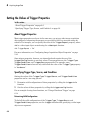
Step 5: Configure Object Properties (Optional)
After creating the video input object and previewing the video stream, you might want
to modify characteristics of the image or other aspects of the acquisition process. You
accomplish this by setting the values of image acquisition object properties. This section
1-14
Getting Started Doing Image Acquisition Programmatically
• Describes the types of image acquisition objects used by the toolbox
• Describes how to view all the properties supported by these objects, with their current
values
• Describes how to set the values of object properties
Types of Image Acquisition Objects
The toolbox uses two types of objects to represent the connection with an image
acquisition device:
• Video input objects
• Video source objects
A video input object represents the connection between MATLAB and a video acquisition
device at a high level. The properties supported by the video input object are the same for
every type of device. You created a video input object using the videoinput function in
step 3.
When you create a video input object, the toolbox automatically creates one or more
video source objects associated with the video input object. Each video source object
represents a collection of one or more physical data sources that are treated as a single
entity. The number of video source objects the toolbox creates depends on the device
and the video format you specify. At any one time, only one of the video source objects,
called the selected source, can be active. This is the source used for acquisition. For more
information about these image acquisition objects, see “Creating Image Acquisition
Objects” on page 5-8.
Viewing Object Properties
To view a complete list of all the properties supported by a video input object or a video
source object, use the get function. To list the properties of the video input object created
in step 3, enter this code at the MATLAB prompt.
get(vid)
The get function lists all the properties of the object with their current values.
General Settings:
DeviceID = 1
DiskLogger = []
DiskLoggerFrameCount = 0
EventLog = [1x0 struct]
FrameGrabInterval = 1
1-15
1
Getting Started
FramesAcquired = 0
FramesAvailable = 0
FramesPerTrigger = 10
Logging = off
LoggingMode = memory
Name = Y8_1024x768-dcam-1
NumberOfBands = 1
Previewing = on
ReturnedColorSpace = grayscale
ROIPosition = [0 0 1024 768]
Running = off
Tag =
Timeout = 10
Type = videoinput
UserData = []
VideoFormat = Y8_1024x768
VideoResolution = [1024 768]
.
.
.
To view the properties of the currently selected video source object associated with this
video input object, use the getselectedsource function in conjunction with the get
function. The getselectedsource function returns the currently active video source.
To list the properties of the currently selected video source object associated with the
video input object created in step 3, enter this code at the MATLAB prompt.
get(getselectedsource(vid))
The get function lists all the properties of the object with their current values.
Note Video source object properties are device specific. The list of properties supported by
the device connected to your system might differ from the list shown in this example.
General Settings:
Parent = [1x1 videoinput]
Selected = on
SourceName = input1
Tag =
Type = videosource
Device Specific Properties:
1-16
Getting Started Doing Image Acquisition Programmatically
FrameRate = 15
Gain = 2048
Shutter = 2715
Setting Object Properties
To set the value of a video input object property or a video source object property, you
reference the object property as you would a field in a structure, using dot notation.
Some properties are read only; you cannot set their values. These properties typically
provide information about the state of the object. Other properties become read only
when the object is running. To view a list of all the properties you can set, use the set
function, specifying the object as the only argument.
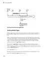
To implement continuous image acquisition, the example sets the TriggerRepeat
property to Inf. To set this property, enter this code at the MATLAB prompt.
vid.TriggerRepeat = Inf;
To help the application keep up with the incoming video stream while processing data,
the example sets the FrameGrabInterval property to 5. This specifies that the object
acquire every fifth frame in the video stream. (You might need to experiment with
the value of the FrameGrabInterval property to find a value that provides the best
response with your image acquisition setup.) This example shows how you can set the
value of an object property by referencing the property as you would reference a field in a
MATLAB structure.
vid.FrameGrabInterval = 5;
To set the value of a video source object property, you must first use the
getselectedsource function to retrieve the object. (You can also get the selected
source by searching the video input object Source property for the video source object
that has the Selected property set to 'on'.)
To illustrate, the example assigns a value to the Tag property.
vid_src = getselectedsource(vid);
vid_src.Tag = 'motion detection setup';
Step 6: Acquire Image Data
After you create the video input object and configure its properties, you can acquire data.
This is typically the core of any image acquisition application, and it involves these steps:
1-17
1
Getting Started
• Starting the video input object — You start an object by calling the start
function. Starting an object prepares the object for data acquisition. For example,
starting an object locks the values of certain object properties (they become read
only). Starting an object does not initiate the acquiring of image frames, however. The
initiation of data logging depends on the execution of a trigger.
The following example calls the start function to start the video input object. Objects
stop when they have acquired the requested number of frames. Because the example
specifies a continuous acquisition, you must call the stop function to stop the object.
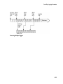
• Triggering the acquisition — To acquire data, a video input object must execute
a trigger. Triggers can occur in several ways, depending on how the TriggerType
property is configured. For example, if you specify an immediate trigger, the object
executes a trigger automatically, immediately after it starts. If you specify a manual
trigger, the object waits for a call to the trigger function before it initiates data
acquisition. For more information, see “Acquiring Image Data” on page 6-2.
In the example, because the TriggerType property is set to 'immediate' (the
default) and the TriggerRepeat property is set to Inf, the object automatically
begins executing triggers and acquiring frames of data, continuously.
• Bringing data into the MATLAB workspace — The toolbox stores acquired data
in a memory buffer, a disk file, or both, depending on the value of the video input
object LoggingMode property. To work with this data, you must bring it into the
MATLAB workspace. To bring multiple frames into the workspace, use the getdata
function. Once the data is in the MATLAB workspace, you can manipulate it as
you would any other data. For more information, see “Working with Image Data in
MATLAB Workspace” on page 7-11.
Note The toolbox provides a convenient way to acquire a single frame of image data that
doesn't require starting or triggering the object. See “Bringing a Single Frame into the
Workspace” on page 7-10 for more information.
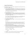
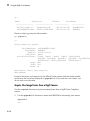
Running the Example
To run the example, enter the following code at the MATLAB prompt. The example
loops until a specified number of frames have been acquired. In each loop iteration,
the example calls getdata to bring the two most recent frames into the MATLAB
workspace. To detect motion, the example subtracts one frame from the other, creating
1-18
Getting Started Doing Image Acquisition Programmatically
a difference image, and then displays it. Pixels that have changed values in the acquired
frames will have nonzero values in the difference image.
The getdata function removes frames from the memory buffer when it brings them into
the MATLAB workspace. It is important to move frames from the memory buffer into the
MATLAB workspace in a timely manner. If you do not move the acquired frames from
memory, you can quickly exhaust all the memory available on your system.
Note The example uses functions in the Image Processing Toolbox software.
% Create video input object.
vid = videoinput('dcam',1,'Y8_1024x768')
% Set video input object properties for this application.
vid.TriggerRepeat = 100;
vid.FrameGrabInterval = 5;
% Set value of a video source object property.
vid_src = getselectedsource(vid);
vid_src.Tag = 'motion detection setup';
% Create a figure window.
figure;
% Start acquiring frames.
start(vid)
% Calculate difference image and display it.
while(vid.FramesAvailable >= 2)
data = getdata(vid,2);
diff_im = imabsdiff(data(:,:,:,1),data(:,:,:,2));
imshow(diff_im);
drawnow
% update figure window
end
stop(vid)
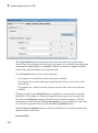
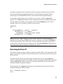
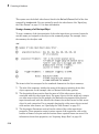
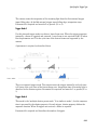
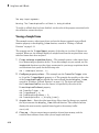
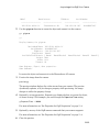
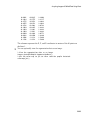
Note that a drawnow is used after the call to imshow in order to ensure that the figure
window is updated. This is good practice when updating a GUI or figure inside a loop.
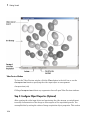
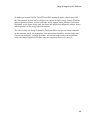
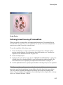
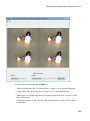
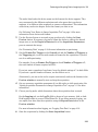
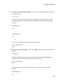
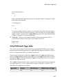
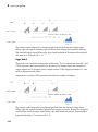
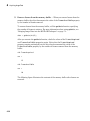
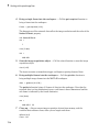
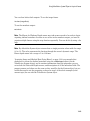
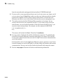
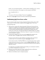
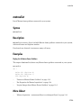
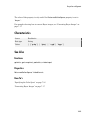
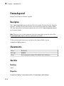
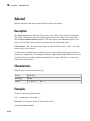
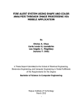
The following figure shows how the example displays detected motion. In the figure,
areas representing movement are displayed.
1-19
1
Getting Started
Figure Window Displayed by Example
Image Data in the MATLAB Workspace
In the example, the getdata function returns the image frames in the variable data as
a 480-by-640-by-1-by-10 array of 8-bit data (uint8).
whos
Name
data
dev_info
info
vid
vid_src
Size
4-D
1x1
1x1
1x1
1x1
Bytes
3072000
1601
2467
1138
726
Class
uint8 array
struct array
struct array
videoinput object
videosource object
The height and width of the array are primarily determined by the video resolution of
the video format. However, you can use the ROIPosition property to specify values that
supersede the video resolution. Devices typically express video resolution as column-byrow; MATLAB expresses matrix dimensions as row-by-column.
The third dimension represents the number of color bands in the image. Because the
example data is a grayscale image, the third dimension is 1. For RGB formats, image
frames have three bands: red is the first, green is the second, and blue is the third. The
fourth dimension represents the number of frames that have been acquired from the
video stream.
1-20
Getting Started Doing Image Acquisition Programmatically
Step 7: Clean Up
When you finish using your image acquisition objects, you can remove them from
memory and clear the MATLAB workspace of the variables associated with these objects.
delete(vid)
clear
close(gcf)
For more information, see “Deleting Image Acquisition Objects” on page 5-25.
1-21
2
Introduction
This chapter describes the Image Acquisition Toolbox software and its components.
• “Toolbox Components Overview” on page 2-2
• “Setting Up Image Acquisition Hardware” on page 2-7
• “Previewing Data” on page 2-10
2
Introduction
Toolbox Components Overview
In this section...
“Introduction” on page 2-2
“Toolbox Components” on page 2-3
“The Image Processing Toolbox Software Required to Use the Image Acquisition Toolbox
Software” on page 2-4
“The Image Acquisition Tool (GUI)” on page 2-5
“Supported Devices” on page 2-5
Introduction
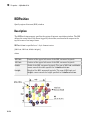
Image Acquisition Toolbox enables you to acquire images and video from cameras
and frame grabbers directly into MATLAB and Simulink. You can detect hardware
automatically, and configure hardware properties. Advanced workflows let you trigger
acquisitions while processing in-the-loop, perform background acquisitions, and
synchronize sampling across several multimodal devices. With support for multiple
hardware vendors and industry standards, you can use imaging devices, ranging from
inexpensive Web cameras to high-end scientific and industrial devices that meet lowlight, high-speed, and other challenging requirements.
The Image Acquisition Toolbox software implements an object-oriented approach to
image acquisition. Using toolbox functions, you create an object that represents the
connection between MATLAB and specific image acquisition devices. Using properties of
the object you can control various aspects of the acquisition process, such as the amount
of video data you want to capture. “Creating Image Acquisition Objects” on page 5-8
describes how to create objects.
Once you establish a connection to a device, you can acquire image data by executing a
trigger. In the toolbox, all image acquisition is initiated by a trigger. The toolbox supports
several types of triggers that let you control when an acquisition takes place. For
example, using hardware triggers you can synchronize an acquisition with an external
device. “Acquiring Image Data” on page 6-2 describes how to trigger the acquisition
of image data.
To work with the data you acquire, you must bring it into the MATLAB workspace.
When the frames are acquired, the toolbox stores them in a memory buffer. The toolbox
2-2
Toolbox Components Overview
provides several ways to bring one or more frames of data into the workspace where you
can manipulate it as you would any other multidimensional numeric array. “Bringing
Image Data into the MATLAB Workspace” on page 7-3 describes this process.
Finally, you can enhance your image acquisition application by using event callbacks.
The toolbox has defined certain occurrences, such as the triggering of an acquisition, as
events. You can associate the execution of a particular function with a particular event.
“Using Events and Callbacks” on page 8-2 describes this process.
Note: With previous versions of the Image Acquisition Toolbox, the files for all of the
adaptors were included in your installation. Starting with version R2014a, each adaptor
is available separately through the Support Package Installer. In order to use the Image
Acquisition Toolbox, you must install the adaptor that your camera uses. See “Image
Acquisition Support Packages for Hardware Adaptors” on page 4-2 for information
about installing the adaptors.
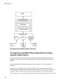
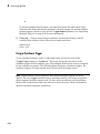
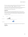
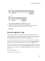
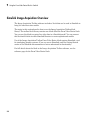
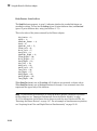
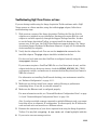
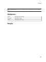
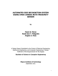
Toolbox Components
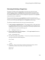
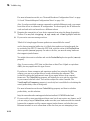
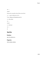
The toolbox uses components called hardware device adaptors to connect to devices
through their drivers. The toolbox includes adaptors that support devices produced by
several vendors of image acquisition equipment. In addition, the toolbox includes an
adaptor for generic Windows video acquisition devices.
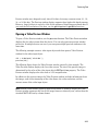
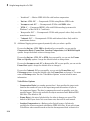
The following figure shows these components and their relationship.
2-3
2
Introduction
The Image Acquisition Toolbox Software Components
The Image Processing Toolbox Software Required to Use the Image
Acquisition Toolbox Software
The Image Acquisition Toolbox product, including the Image Acquisition Tool, now
requires you to have a license for the Image Processing Toolbox product starting in
R2008b.
If you already have the Image Processing Toolbox product, you do not need to do
anything.
If you do not have the Image Processing Toolbox product, the Image Acquisition
Toolbox software R2008a and earlier will continue to work. If you want to use R2008b
or future releases, and you have a current active license for the Image Acquisition
Toolbox software, you can download the Image Processing Toolbox product for free. New
2-4
Toolbox Components Overview
customers will need to purchase both products to use the Image Acquisition Toolbox
product.
If you have any questions, please contact MathWorks customer service.
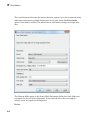
The Image Acquisition Tool (GUI)
The functionality of the Image Acquisition Toolbox software is available in a desktop
application. You connect directly to your hardware in the tool and can then set
acquisition parameters, and preview and acquire image data. You can log the data to
MATLAB in several formats, and also generate a VideoWriter file, right from the tool.
To open the tool, type imaqtool at the MATLAB command line, or select Image
Acquisition on the Apps tab in MATLAB. The tool has extensive Help in the desktop.
As you click in different panes of the user interface, the relevant Help appears in the
Image Acquisition Tool Help pane.
Most of the User's Guide describes performing tasks using the toolbox via the MATLAB
command line. To learn how to use the desktop tool, see “Getting Started with the Image
Acquisition Tool” on page 3-5.
Supported Devices
The Image Acquisition Toolbox software includes adaptors that provide support for
several vendors of professional grade image acquisition equipment, devices that support
the IIDC 1394-based Digital Camera Specification (DCAM), and devices that provide
Windows Driver Model (WDM) or Video for Windows (VFW) drivers, such as USB and
IEEE® 1394 (FireWire, i.LINK®) Web cameras, Digital video (DV) camcorders, and
TV tuner cards. For the latest information about supported hardware, visit the Image
Acquisition Toolbox product page at the MathWorks Web site (www.mathworks.com/
products/imaq).
The DCAM specification, developed by the 1394 Trade Association, describes a generic
interface for exchanging data with IEEE 1394 (FireWire) digital cameras that is often
used in scientific applications. The toolbox's DCAM adaptor supports Format 7, also
known as partial scan mode. The toolbox uses the prefix F7_ to identify Format 7 video
format names.
2-5
2
Introduction
Note: The toolbox supports only connections to IEEE 1394 (FireWire) DCAM-compliant
devices using the Carnegie Mellon University DCAM driver. The toolbox is not
compatible with any other vendor-supplied driver, even if the driver is DCAM compliant.
You can add support for additional hardware by writing an adaptor. For more
information, see “Support for Additional Hardware” on page 15-2.
Note: With previous versions of the Image Acquisition Toolbox, the files for all of the
adaptors were included in your installation. Starting with version R2014a, each adaptor
is available separately through the Support Package Installer. In order to use the Image
Acquisition Toolbox, you must install the adaptor that your camera uses. See “Image
Acquisition Support Packages for Hardware Adaptors” on page 4-2 for information
about installing the adaptors.
2-6
Setting Up Image Acquisition Hardware
Setting Up Image Acquisition Hardware
In this section...
“Introduction” on page 2-7
“Setting Up Frame Grabbers” on page 2-7
“Setting Up Generic Windows Video Acquisition Devices” on page 2-8
“Setting Up DCAM Devices” on page 2-8
“Resetting Your Image Acquisition Hardware” on page 2-8
“A Note About Frame Rates and Processing Speed” on page 2-8
Introduction
To acquire image data, you must perform the setup required by your particular image
acquisition device. In a typical image acquisition setup, an image acquisition device, such
as a camera, is connected to a computer via an image acquisition board, such as a frame
grabber, or via a Universal Serial Bus (USB) or IEEE 1394 (FireWire) port. The setup
required varies with the type of device.
After installing and configuring your image acquisition hardware, start MATLAB on
your computer by double-clicking the icon on your desktop. You do not need to perform
any special configuration of MATLAB to acquire data.
Note: With previous versions of the Image Acquisition Toolbox, the files for all of the
adaptors were included in your installation. Starting with version R2014a, each adaptor
is available separately through the Support Package Installer. In order to use the Image
Acquisition Toolbox, you must install the adaptor that your camera uses. See “Image
Acquisition Support Packages for Hardware Adaptors” on page 4-2 for information
about installing the adaptors.
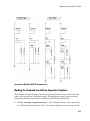
Setting Up Frame Grabbers
For frame grabbers, also known as imaging boards, setup typically involves the following
tasks:
• Installing the frame grabber in your computer
2-7
2
Introduction
• Installing any software drivers required by the frame grabber. These are supplied by
the device vendor.
• Connecting the camera, or other image acquisition device, to a connector on the frame
grabber
• Verifying that the camera is working properly by running the application software
that came with the frame grabber and viewing a live video stream
Setting Up Generic Windows Video Acquisition Devices
IEEE 1394 (FireWire) and generic Windows video acquisition devices that use Windows
Driver Model (WDM) or Video for Windows (VFW) device drivers typically require less
setup. Plug the device into the USB or IEEE 1394 (FireWire) port on your computer and
install the device driver provided by the vendor.
Setting Up DCAM Devices
If you intend to access a DCAM-compliant IEEE 1394 (FireWire) camera, you must
install and configure the Carnegie Mellon University (CMU) DCAM driver. The toolbox
is not compatible with any other vendor-supplied driver, even if the driver is DCAM
compliant. See “Installing the CMU DCAM Driver on Windows” on page 16-10 for
more information.
Resetting Your Image Acquisition Hardware
To return MATLAB and your image acquisition hardware to a known state, where no
image acquisition objects exist and the hardware is not configured, use the imaqreset
function.
If you connect another image acquisition device to your system after MATLAB is started,
you can use imaqreset to make the toolbox aware of the new hardware.
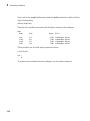
A Note About Frame Rates and Processing Speed
The frame rate describes how fast an image acquisition device provides data, typically
measured as frames per second.
Devices that support industry-standard video formats must provide frames at the rate
specified by the standard. For RS170 and NTSC, the standard dictates a frame rate of
2-8
Setting Up Image Acquisition Hardware
30 frames per second (30 Hz). The CCIR and PAL standards define a frame rate of 25
Hz. Nonstandard devices can be configured to operate at higher rates. Generic Windows
image acquisition devices, such as webcams, might support many different frame rates.
Depending on the device being used, the frame rate might be configurable using a devicespecific property of the image acquisition object.
The rate at which the Image Acquisition Toolbox software can process images depends
on the processor speed, the complexity of the processing algorithm, and the frame rate.
Given a fast processor, a simple algorithm, and a frame rate tuned to the acquisition
setup, the Image Acquisition Toolbox software can process data as it comes in.
2-9
2
Introduction
Previewing Data
In this section...
“Introduction” on page 2-10
“Opening a Video Preview Window” on page 2-11
“Stopping the Preview Video Stream” on page 2-12
“Closing a Video Preview Window” on page 2-13
“Previewing Data in Custom GUIs” on page 2-13
“Performing Custom Processing of Previewed Data” on page 2-15
Introduction
After you connect MATLAB to the image acquisition device you can view the live video
stream using the Video Preview window. Previewing the video data can help you make
sure that the image being captured is satisfactory.
For example, by looking at a preview, you can verify that the lighting and focus are
correct. If you change characteristics of the image, by using video input object and video
source object properties, the image displayed in the Video Preview window changes to
reflect the new property settings.
The following sections provide more information about using the Video Preview window.
• “Opening a Video Preview Window” on page 2-11
• “Stopping the Preview Video Stream” on page 2-12
• “Closing a Video Preview Window” on page 2-13
Instead of using the toolbox's Video Preview window, you can display the live video
preview stream in any Handle Graphics® image object you specify. In this way, you can
include video previewing in a GUI of your own creation. The following sections describe
this capability.
• “Previewing Data in Custom GUIs” on page 2-13
• “Performing Custom Processing of Previewed Data” on page 2-15
Note: The Image Acquisition Toolbox Preview window and the Preview window that is
built into the Image Acquisition Tool support the display of up to 16-bit image data. The
2-10
Previewing Data
Preview window was designed to only show 8-bit data, but many cameras return 10-, 12-,
14-, or 16-bit data. The Preview window display supports these higher bit-depth cameras.
However, larger bit data is scaled to 8-bit for the purpose of displaying previewed data. If
you need the full resolution of the data, use the getsnapshot or getdata functions.
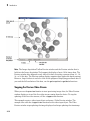
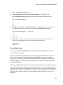
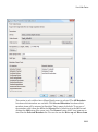
Opening a Video Preview Window
To open a Video Preview window, use the preview function. The Video Preview window
displays the live video stream from the device. You can only open one preview window
per device. If multiple devices are used, you can open multiple preview windows at the
same time.
The following example creates a video input object and then opens a Video Preview
window for the video input object.
vid = videoinput('winvideo');
preview(vid);
The following figure shows the Video Preview window created by this example. The
Video Preview window displays the live video stream. The size of the preview image is
determined by the value of the video input object's ROIPosition property. The Video
Preview window displays the video data at 100% magnification.
In addition to the preview image, the Video Preview window includes information about
the image, such as the timestamp of the video frame, the video resolution, and the
current status of the video input object.
Note Because video formats typically express resolution as width-by-height, the Video
Preview window expresses the size of the image frame as column-by-row, rather than the
standard MATLAB row-by-column format.
2-11
2
Introduction
Note: The Image Acquisition Toolbox Preview window and the Preview window that is
built into the Image Acquisition Tool support the display of up to 16-bit image data. The
Preview window was designed to only show 8-bit data, but many cameras return 10-, 12-,
14-, or 16-bit data. The Preview window display supports these higher bit-depth cameras.
However, larger bit data is scaled to 8-bit for the purpose of displaying previewed data. If
you need the full resolution of the data, use the getsnapshot or getdata functions.
Stopping the Preview Video Stream
When you use the preview function to start previewing image data, the Video Preview
window displays a view of the live video stream coming from the device. To stop the
updating of the live video stream, call the stoppreview function.
This example creates a video input object and opens a Video Preview window. The
example then calls the stoppreview function on this video input object. The Video
Preview window stops updating the image displayed and stops updating the timestamp.
2-12
Previewing Data
The status displayed in the Video Preview window also changes to indicate that
previewing has been stopped.
vid = videoinput('winvideo');
preview(vid)
stoppreview(vid)
To restart the video stream in the Video Preview window, call preview again on the
same video input object.
preview(vid)
Closing a Video Preview Window
To close a particular Video Preview window, use the closepreview function, specifying
the video input object as an argument. You do not need to stop the live video stream
displayed in the Video Preview window before closing it.
closepreview(vid)
To close all currently open Video Preview windows, use the closepreview function
without any arguments.
closepreview
Note When called without an argument, the closepreview function only closes Video
Preview windows. The closepreview function does not close any other figure windows
in which you have directed the live preview video stream. For more information, see
“Previewing Data in Custom GUIs” on page 2-13.
Previewing Data in Custom GUIs
Instead of using the toolbox's Video Preview window, you can use the preview function
to direct the live video stream to any Handle Graphics image object. In this way, you
can incorporate the toolbox's previewing capability in a GUI of your own creation. (You
can also perform custom processing as the live video is displayed. For information, see
“Performing Custom Processing of Previewed Data” on page 2-15.)
To use this capability, create an image object and then call the preview function,
specifying a handle to the image object as an argument. The preview function outputs
the live video stream to the image object you specify.
2-13
2
Introduction
The following example creates a figure window and then creates an image object in the
figure, the same size as the video frames. The example then calls the preview function,
specifying a handle to the image object.
% Create a video input object.
vid = videoinput('winvideo');
% Create a figure window. This example turns off the default
% toolbar, menubar, and figure numbering.
figure('Toolbar','none',...
'Menubar', 'none',...
'NumberTitle','Off',...
'Name','My Preview Window');
% Create the image object in which you want to display
% the video preview data. Make the size of the image
% object match the dimensions of the video frames.
vidRes = vid.VideoResolution;
nBands = vid.NumberOfBands;
hImage = image( zeros(vidRes(2), vidRes(1), nBands) );
% Display the video data in your GUI.
preview(vid, hImage);
When you run this example, it creates the GUI shown in the following figure.
2-14
Previewing Data
Custom Preview
Performing Custom Processing of Previewed Data
When you specify an image object to the preview function (see “Previewing Data in
Custom GUIs” on page 2-13), you can optionally also specify a function that preview
executes every time it receives an image frame.
To use this capability, follow these steps:
1
Create the function you want executed for each image frame, called the update
preview window function. For information about this function, see “Creating the
Update Preview Window Function” on page 2-16.
2
Create an image object.
3
Configure the value of the image object's 'UpdatePreviewWindowFcn' applicationdefined data to be a function handle to your update preview window function. For
more information, see “Specifying the Update Preview Function” on page 2-17.
4
Call the preview function, specifying the handle of the image object as an argument.
Note If you specify an update preview window function, in addition to whatever
processing your function performs, it must display the video data in the image object.
You can do this by updating the CData of the image object with the incoming video
frames. For some performance guidelines about updating the data displayed in an image
object, see Technical Solution 1-1B022.
2-15
2
Introduction
Creating the Update Preview Window Function
When preview calls the update preview window function you specify, it passes your
function the following arguments.
Argument
Description
obj
Handle to the video input object being previewed
event
A data structure containing the following fields:
himage
Data
Current image frame specified as an H-by-W-byB array, where H is the image height and W is
the image width, as specified in the ROIPosition
property, and B is the number of color bands, as
specified in the NumberOfBands property
Resolution
Text string specifying the current image width and
height, as defined by the ROIPosition property
Status
String describing the status of the video input
object
Timestamp
String specifying the time associated with the
current image frame, in the format hh:mm:ss:ms
Handle to the image object in which the data is to be displayed
The following example creates an update preview window function that displays the
timestamp of each incoming video frame as a text label in the custom GUI. The update
preview window function uses getappdata to retrieve a handle to the text label
uicontrol object from application-defined data in the image object. The custom GUI
stores this handle to the text label uicontrol object — see “Specifying the Update
Preview Function” on page 2-17.
Note that the update preview window function also displays the video data by updating
the CData of the image object.
function mypreview_fcn(obj,event,himage)
% Example update preview window function.
% Get timestamp for frame.
tstampstr = event.Timestamp;
% Get handle to text label uicontrol.
2-16
Previewing Data
ht = getappdata(himage,'HandleToTimestampLabel');
% Set the value of the text label.
ht.String = tstampstr;
% Display image data.
himage.CData = event.Data
Specifying the Update Preview Function
To use an update preview window function, store a function handle to your function in
the 'UpdatePreviewWindowFcn' application-defined data of the image object. The
following example uses the setappdata function to configure this application-defined
data to a function handle to the update preview window function described in “Creating
the Update Preview Window Function” on page 2-16.
This example extends the simple custom preview window created in “Previewing Data
in Custom GUIs” on page 2-13. This example adds three push button uicontrol
objects to the GUI: Start Preview, Stop Preview, and Close Preview.
In addition, to illustrate using an update preview window function, the example GUI
includes a text label uicontrol object to display the timestamp value. The update
preview window function updates this text label each time a framed is received. The
example uses setappdata to store a handle to the text label uicontrol object in
application-defined data in the image object. The update preview window function
retrieves this handle to update the timestamp display.
% Create a video input object.
vid = videoinput('winvideo');
% Create a figure window. This example turns off the default
% toolbar and menubar in the figure.
hFig = figure('Toolbar','none',...
'Menubar', 'none',...
'NumberTitle','Off',...
'Name','My Custom Preview GUI');
% Set up the push buttons
uicontrol('String', 'Start Preview',...
'Callback', 'preview(vid)',...
'Units','normalized',...
'Position',[0 0 0.15 .07]);
uicontrol('String', 'Stop Preview',...
2-17
2
Introduction
'Callback', 'stoppreview(vid)',...
'Units','normalized',...
'Position',[.17 0 .15 .07]);
uicontrol('String', 'Close',...
'Callback', 'close(gcf)',...
'Units','normalized',...
'Position',[0.34 0 .15 .07]);
% Create the text label for the timestamp
hTextLabel = uicontrol('style','text','String','Timestamp', ...
'Units','normalized',...
'Position',[0.85 -.04 .15 .08]);
% Create the image object in which you want to
% display the video preview data.
vidRes = vid.VideoResolution;
imWidth = vidRes(1);
imHeight = vidRes(2);
nBands = vid.NumberOfBands;
hImage = image( zeros(imHeight, imWidth, nBands) );
% Specify the size of the axes that contains the image object
% so that it displays the image at the right resolution and
% centers it in the figure window.
figSize = get(hFig,'Position');
figWidth = figSize(3);
figHeight = figSize(4);
gca.unit = 'pixels';
gca.position = [ ((figWidth - imWidth)/2)...
((figHeight - imHeight)/2)...
imWidth imHeight ];
% Set up the update preview window function.
setappdata(hImage,'UpdatePreviewWindowFcn',@mypreview_fcn);
% Make handle to text label available to update function.
setappdata(hImage,'HandleToTimestampLabel',hTextLabel);
preview(vid, hImage);
When you run this example, it creates the GUI shown in the following figure. Each time
preview receives a video frame, it calls the update preview window function that you
specified, which updates the timestamp text label in the GUI.
2-18
Previewing Data
Custom Preview GUI with Timestamp Text Label
2-19
3
Using the Image Acquisition Tool GUI
• “The Image Acquisition Tool Desktop” on page 3-2
• “Getting Started with the Image Acquisition Tool” on page 3-5
• “Selecting Your Device in Image Acquisition Tool” on page 3-8
• “Setting Acquisition Parameters in Image Acquisition Tool” on page 3-11
• “Previewing and Acquiring Data in Image Acquisition Tool” on page 3-28
• “Exporting Data in the Image Acquisition Tool” on page 3-35
• “Saving Image Acquisition Tool Configurations” on page 3-39
• “Exporting Image Acquisition Tool Hardware Configurations to MATLAB” on page
3-41
• “Saving and Copying Image Acquisition Tool Session Log” on page 3-43
• “Registering a Third-Party Adaptor in the Image Acquisition Tool” on page 3-46
3
Using the Image Acquisition Tool GUI
The Image Acquisition Tool Desktop
In this section...
“Opening the Tool” on page 3-2
“Parts of the Desktop” on page 3-2
Opening the Tool
Image Acquisition Toolbox functionality is available in a desktop application. You
connect directly to your hardware in the tool and can preview and acquire image data.
You can log the data to MATLAB in several formats, and also generate a VideoWriter
file, right from the tool.
The Image Acquisition Tool provides a desktop environment that integrates a preview/
acquisition area with Acquisition Parameters so that you can change settings and see the
changes dynamically applied to your image data.
To open the Image Acquisition Tool, do one of the following:
• Type imaqtool at the MATLAB command line.
• Select Image Acquisition on the Apps tab in MATLAB.
Note: The right pane in the tool is the Desktop Help pane. As you work in the tool the
Help will provide information for the part of the interface that you are working in. If the
Desktop Help is closed, you can open it be selecting Desktop > Desktop Help.
Parts of the Desktop
The Image Acquisition Tool has the following panes.
3-2
The Image Acquisition Tool Desktop
• Hardware Browser – Shows the image acquisition devices currently connected
to your system. Each device is a separate node in the browser. All of the formats
the device supports are listed under the device. Each device's default format is
indicated in parentheses. Select the device format or camera file you want to use for
the acquisition. When the format is selected, you can then set acquisition parameters
and preview your data. See “Selecting Your Device in Image Acquisition Tool” on page
3-8 for more information about using the Hardware Browser.
• Preview window – Use to preview and acquire image data from the selected device
format, and to export data that has been acquired in memory to a MAT-file, the
3-3
3
Using the Image Acquisition Tool GUI
MATLAB Workspace, VideoWriter, or to tools provided by the Image Processing
Toolbox software. See “Previewing and Acquiring Data in Image Acquisition Tool” on
page 3-28 for more information about using the Preview window.
• Acquisition Parameters – Use these tabs to set up general acquisition parameters,
such as frames per trigger and color space, device-specific properties, logging options,
triggering options, and region of interest. Settings you make on any tab will apply
to the currently selected device format in the Hardware Browser. See “Setting
Acquisition Parameters in Image Acquisition Tool” on page 3-11 for more
information about using the Acquisition Parameters. Also see the Help for each tab
while using the tool for more details. When you click any tab, the help for that tab will
appear in the Desktop Help pane.
• Information pane – Displays a summary of information about the selected node in
the Hardware Browser.
• Session Log – Displays a dynamically generated log of the commands that
correspond to actions taken in the tool. You can save the log to a MATLAB code file or
copy it.
• Desktop Help – Displays Help for the pane of the desktop that has focus. Click
inside a pane for help on that area of the tool. For the Acquisition Parameters
pane, click each tab to display information about the settings for that tab.
If the Desktop Help is closed, you can open it by selecting Desktop > Desktop
Help.
3-4
Getting Started with the Image Acquisition Tool
Getting Started with the Image Acquisition Tool
This section describes an example of the basic work flow of using the Image Acquisition
Tool to preview, acquire, and save image data. You don't need to do every step shown
here, and you can change the order of some steps.
For information on the parts of the Desktop GUI or how to open the Tool, see “The Image
Acquisition Tool Desktop” on page 3-2.
Note: With previous versions of the Image Acquisition Toolbox, the files for all of the
adaptors were included in your installation. Starting with version R2014a, each adaptor
is available separately through the Support Package Installer. In order to use the
Image Acquisition Tool, you must install the adaptor that your camera uses. See “Image
Acquisition Support Packages for Hardware Adaptors” on page 4-2 for information
about installing the adaptors.
1
Decide which device you want to work with.
The Hardware Browser shows the image acquisition devices currently connected
to your system. If the device you want to use is not connected to your system, plug it
in and then select Tools > Refresh Image Acquisition Hardware to display the
new device in the Hardware Browser.
2
Choose the format to work with.
The nodes listed under the device name are the formats the device supports. They
may correspond to the different resolutions and color spaces that your device
supports, or to different video standards or camera configurations. This information
comes from your device adaptor. Select the format you want to use.
3
Preview to check that the device is working and the image is what you expect.
Click the Start Preview button.
If necessary, physically adjust the device to achieve the desired image area, or use
the Region of Interest tab to define the acquisition region.
4
Decide how many frames you want to acquire.
The number of frames that will be acquired when you start the acquisition is
dependent on what is set in the Frames Per Trigger field on the General tab
3-5
3
Using the Image Acquisition Tool GUI
and the Number of Triggers field on the Triggering tab. For example, if you
set Frames Per Trigger to 4 and Number of Triggers to 2, the total number of
frames acquired will be 8.
If you just want a snapshot of one frame, leave the default settings of 1 in both of
those fields. If you want a specific number of frames, use the fields to set it.
Alternatively, you can set the tool to acquire continuously and use the buttons in the
Preview Window to manually start and stop the acquisition. This is discussed in a
later step.
5
Set any general or device-specific parameters you need to set, on those tabs of the
Acquisition Parameters pane, or use the default settings.
6
Choose your log mode, which determines where the acquisition data is stored.
On the Logging tab, use the Log To field to choose to log to memory, disk, or both.
Disk logging results in a saved VideoWriter file. If you choose memory logging, you
can export your data after the acquisition using the Export Data button on the
Preview Window.
For more information on logging, see the Help for the Logging tab in the Desktop
Help pane in the tool.
7
Start the acquisition by clicking the Start Acquisition button.
– If you set Trigger Type (on the Triggering tab) to Immediate, the tool will
immediately start logging data.
– If you set Trigger Type to Manual, click the Trigger button when you want to
start logging data.
8
Stop the acquisition.
– If you set Frames Per Trigger (on the General tab) to 1 or any other number,
your acquisition will stop when that number of frames is reached.
– If you set Frames Per Trigger to Infinite, click the Stop Acquisition button
to stop the acquisition.
Note that you can also click Stop Acquisition to abort an acquisition if number of
frames was specified.
9
3-6
Optionally you can export data that was saved to memory.
Getting Started with the Image Acquisition Tool
You can export the data that has been acquired in memory to a MAT-file, the
MATLAB Workspace, VideoWriter, or to the Image Tool, Image File, or Movie Player
tools that are provided by the Image Processing Toolbox software using the Export
Data button. For more information, see the “Exporting Data” section of the Desktop
Help on the Preview Window in the Desktop Help pane in the tool.
10 Optionally you can save your configuration(s), using the File > Save Configuration
or File > Export Hardware Configuration menus. For more information about
these commands, see the “Image Acquisition Tool Menus” section of the Help on the
Hardware Browser in the Desktop Help pane in the tool.
3-7
3
Using the Image Acquisition Tool GUI
Selecting Your Device in Image Acquisition Tool
In this section...
“Selecting a Device and Format” on page 3-8
“Adding New Hardware” on page 3-10
“Using a Camera File” on page 3-10
Selecting a Device and Format
The Hardware Browser pane shows the image acquisition devices currently connected
to your system. Each device is a separate node in the browser. All of the formats the
device supports are listed under the device. Each device's default format is indicated in
parentheses. The format information displayed under a device comes from the device's
adaptor.
3-8
Selecting Your Device in Image Acquisition Tool
Select the device format or camera file you want to use for the acquisition by clicking its
name in the tree. When the format is selected, you can then set acquisition parameters
and preview your data.
3-9
3
Using the Image Acquisition Tool GUI
Adding New Hardware
When you open the Image Acquisition Tool, the Hardware Browser automatically
shows the image acquisition devices supported by the toolbox that are currently
connected to your system. If you plug a new device in while the Image Acquisition Tool is
open, select Tools > Refresh Image Acquisition Hardware to display the new device
in the Hardware Browser.
Using a Camera File
If your device supports the use of a camera file, also known as a device configuration file,
you can select it under the device name in the Hardware Browser. For example, some
frame grabbers support them.
Under the device name in the Hardware Browser, you would see a node that says Click
to add camera file... if the device supports the use of camera files.
To use a camera file:
1
In the Hardware Browser, single-click the node under your device name that says
Click to add camera file....
2
In the Specify camera file dialog box, type the path and name of the file, or click the
Browse button to locate it, and then click OK.
The camera file will then become a new node under the device, similar to any of the
formats listed under a device. You can then set acquisition parameters, preview, and
acquire data using it.
Note: The tool ignores hardware trigger configurations included in a camera file. To
configure hardware triggering, use the Trigger tab in the Acquisition Parameters
pane.
3-10
Setting Acquisition Parameters in Image Acquisition Tool
Setting Acquisition Parameters in Image Acquisition Tool
In this section...
“Using the Acquisition Parameters Pane” on page 3-11
“Setting Frames Per Trigger” on page 3-12
“Setting the Color Space” on page 3-13
“Setting Device-Specific Parameters” on page 3-13
“Logging Your Data” on page 3-16
“Setting Up Triggering” on page 3-19
“Setting a Region of Interest” on page 3-22
“Restoring Default Parameters” on page 3-27
Using the Acquisition Parameters Pane
The tool allows you to set acquisition parameters directly in the desktop using the
Acquisition Parameters pane. Settings you make will apply to the currently selected
device format in the Hardware Browser.
The Acquisition Parameters pane contains the following tabs:
• General – Use to set up general acquisition parameters, such as frames per trigger
and color space.
• Device Properties – Use to view or change device-specific properties.
• Logging – Use to set up logging options, such as logging mode, which determines
whether your acquired data is logged to memory, disk, or both. If you want to
generate a VideoWriter file of your data, use the Disk Logging option on this tab.
• Triggering – Use to set up triggering options, such as number of triggers and trigger
type. If you want to do manual triggering using the Trigger button, use the Trigger
Type option on this tab.
• Region of Interest – Use to set a Region of Interest (ROI) if you only want to use
part of an image.
For more detailed information about the settings on each tab, see the Help topic for the
tab while using the tool. When you click a tab, the corresponding topic will appear in the
Desktop Help pane.
3-11
3
Using the Image Acquisition Tool GUI
Note: Once you have changed parameters of a device, you can restore the device's default
parameters by selecting the device format in the Hardware Browser and right-clicking
Clear Selected Hardware Configuration.
Setting Frames Per Trigger
The Frames Per Trigger field on the General tab is used to set the number of frames
per trigger you want to acquire.
• If you want your acquisition to be a specific number of frames per trigger, use the
default of 1 frame, or use the arrows to select the number of frames or type in the
number.
• If you want to acquire frames continuously, set the Frames Per Trigger to
infinite and then use the Stop Acquisition button to stop the acquisition, or do
manual triggering using the Triggering tab.
The number of frames that will be acquired when you start an acquisition depends on
what is set in the Frames Per Trigger field on the General tab and the Number of
Triggers field on the Triggering tab. For example, if you set Frames Per Trigger to 4
and Number of Triggers to 2, the total number of frames acquired will be 8.
3-12
Setting Acquisition Parameters in Image Acquisition Tool
Note that if you set Frames Per Trigger to infinite, you cannot set Number of
Triggers on the Triggering tab.
Note: Some devices need a few frames to warm up, or may always skip the first frame.
If your device does that, change the number of frames accordingly to adjust for that. You
can also adjust for camera warm-up by using manual triggering on the Triggering tab.
Setting the Color Space
Use Color Space on the General tab to set the color space for the selected device
format. The Returned Color Space field has three options: rgb, YCbCr, and
grayscale. The setting that is your device format's default color space is shown as the
default. You can use the arrow to select another setting.
Additionally, if the default color space is grayscale, a value of bayer will be
available in the Returned Color Space field for some devices, and the Bayer Sensor
Alignment field will also be displayed. Use the drop-down list to select one of the four
possible sensor alignments. This feature allows the tool to demosaic Bayer patterns
returned by the hardware and interpolate them into standard RGB color images.
For more information about this feature, see the BayerSensorAlignment property
reference page.
Setting Device-Specific Parameters
View or change device-specific properties using the Device Properties tab. The selected
device's properties appear in the Properties area. The specific properties that appear
depend on your device.
3-13
3
Using the Image Acquisition Tool GUI
The Selected source field specifies the name of the selected source for the current
device. Many device adaptors only have one input source, so for example, this might show
something like input1, port1, or input0 by default. If your device supports multiple
source names, they will appear in the drop-down list.
Use the Properties area to view or edit properties:
• If a property has an edit box or slider, that value is editable.
• If a property has an arrow indicating a drop-down list, then you can select a value
from the list.
• If a property has a value listed that is grayed out, then that value is not currently
editable.
Changes you make in the Properties area are applied to your acquisition or preview
dynamically. For example, to change the exposure for the camera you are using, edit
the value in the Exposure property text field or use the slider to change it. You will
immediately see the change in the Preview window if you are previewing at the time,
or in the next acquisition when you click the Start Acquisition button.
Click the Reset to defaults button to undo any modifications you made and restore the
default settings of the device.
Property Help
3-14
Setting Acquisition Parameters in Image Acquisition Tool
To get help on any of the properties in the Device Properties tab, right-click a property
and select What's This?. A Help window opens and displays the help for the selected
property, as well as the rest of the properties, which are available by scrolling. This is the
same information as the device help you access using the imaqhelp command. For more
detailed information on device-specific properties, see your device's documentation.
Note About Frame Rate
If FrameRate appears in the Properties area, that means your device has a FrameRate
property. The information in the table comes from your device. The value set there will
be the frame rate that your device uses, in frames per second.
If FrameRate does not appear in the list, your device does not support that property.
3-15
3
Using the Image Acquisition Tool GUI
Logging Your Data
Set logging options using the Logging tab. This determines where your data is logged to
when you do an acquisition.
Use the Log to options to select where to log your acquisition. Select one of the following:
• Memory — Acquisition is logged to memory. This means that the acquired data
that you do not otherwise save (using Export Data) will be logged to your system's
memory, and will be available to you only during the acquisition session. The data
will be lost if you do another acquisition, or you close the tool without exporting the
data. This is the default setting.
• Disk — Acquisition is logged to disk as a VideoWriter file, in the location you specify
in the Disk logging area. This means that the acquired data will be logged to disk
and will be available to you there after the acquisition session. After selecting Disk,
the Disk logging area becomes editable and you can enter or browse to the location
and name the file.
• Disk and memory — Acquisition will be logged to both disk, in the location you
specify in the Disk logging area, and memory.
3-16
Setting Acquisition Parameters in Image Acquisition Tool
Disk Logging
If you select Disk or Disk and memory in the Log to options, the Disk logging area
becomes editable so you can designate a file and location to save to.
Note: Disk logging generates a VideoWriter file. If you select a VideoWriter profile that
generates an AVI file, note that AVI files are limited to a bit-depth of 8 bits per pixel for
each band. If you have higher bit data, you should not log it to an AVI file because the
AVI format is restricted to 8-bit data. If you log higher bit data to an AVI file, it will be
scaled and then logged as 8-bit data.
To use disk logging:
1
Click the Browse button to select a location for the file, or enter the name of the
location.
2
In the Save dialog box, browse to the location and then enter a name in the File
name field, and click Save.
Uncompressed AVI is the default profile for color devices and Grayscale AVI is
the default profile for monochrome devices, so the .avi extension is appended to the
name on the Logging tab initially, and the other fields become editable. You can
change the profile in step 4.
3
Optionally select Automatically increment filename if you want the tool to name
subsequent acquisitions using the same root name, plus an incremented number. For
example, if you enter the file name experiment.avi and then select this option, it
will be replaced by experiment_0001.avi, followed by experiment_0002.avi,
etc.
This option is useful if you need to acquire multiple videos of one or more subjects.
For example, a lab technician might want to acquire 10 seconds of video on a group
of five different cultures and save them for later analysis. The technician may want
resulting file names such as sample_0001.avi, sample_0002.avi, etc.
4
You can use any of the profiles offered by VideoWriter. Accept the default profile
(Uncompressed AVI for color devices and Grayscale AVI for monochrome devices)
or select another. Currently supported profiles are:
• 'Motion JPEG 2000' — Compressed Motion JPEG 2000 file. Can log singlebanded (grayscale) data as well as multi-byte data.
3-17
3
Using the Image Acquisition Tool GUI
• 'Archival' — Motion JPEG 2000 file with lossless compression.
• 'Motion JPEG AVI' — Compressed AVI file using Motion JPEG codec.
• 'Uncompressed AVI' — Uncompressed AVI file with RGB24 video.
• 'MPEG-4' — Compressed MPEG-4 file with H.264 encoding (systems with
Windows 7 or Mac OS X 10.7 and later).
• 'Grayscale AVI' — Uncompressed AVI file with grayscale video. Only used for
monochrome devices.
• 'Indexed AVI' — Uncompressed AVI file with indexed video. Only used for
monochrome devices.
5
Additional logging options appear dynamically after you select a profile.
If you select Motion JPEG 2000 or Archival as your profile, you can set the
Compression Ratio, Frame Rate, Lossless Compression, and MJ2 Bit Depth
options. Accept the default values or change them.
If you select Motion JPEG AVI or MPEG-4 as your profile, you can set the Frame
Rate and Quality options. Accept the default values or change them.
If you select Uncompressed AVI or Grayscale AVI as your profile, you can set the
Frame Rate option. Accept the default value or change it.
If you select Indexed AVI as your profile, you can set the Frame Rate and
Colormap options. Accept the default value for Frame Rate or change it. You must
enter a Colormap value. See the “VideoWriter Options” section below for more
information.
VideoWriter Options
• Compression Ratio is a number greater than 1 that specifies the target ratio
between the number of bytes in the input image and the number of bytes in
the compressed image. The data is compressed as much as possible, up to the
specified target. This is only available for objects associated with Motion JPEG
2000 files. The default is 10.
• Frame Rate is the rate of playback for the video in frames per second. The
default is 30. If your device has a set frame rate, that will be used instead.
• Lossless Compression is a Boolean value (logical true or false) only
available for objects associated with Motion JPEG 2000 files. If you select true,
VideoWriter uses reversible mode so that the decompressed data is identical to
3-18
Setting Acquisition Parameters in Image Acquisition Tool
the input data, and ignores any specified value for CompressionRatio. The
default is false for the Motion JPEG 2000 profile, and true for the Archival
profile.
• MJ2 Bit Depth is the number of least significant bits in the input image data,
from 1 to 16. This is only available for objects associated with Motion JPEG 2000
files. If you do not specify a value, VideoWriter sets the bit depth based on the
input data type. For example, if the input data is an array of uint8 or int8 values,
MJ2BitDepth is 8.
• Quality is a number from 0 to 100. Higher quality numbers result in higher
video quality and larger file sizes. Lower quality numbers result in lower video
quality and smaller file sizes. Only available for objects associated with the
Motion JPEG AVI profile. The default is 75.
• Colormap is a value that specifies the intensity of red, green, and blue for the
image. Type in a value, such as hsv(128), or the name of one of the built-in
MATLAB colormaps, such as jet or hot. For a list of the built-in colormaps, see
the colormap function in the MATLAB documentation.
6
After setting your profile and options, start your acquisition to log a VideoWriter file
to disk.
Note about bit size of AVI files
AVI files are limited to a bit depth of 8 bits per pixel for each band. If you have higher bit
data, you should not log it to a profile that creates an AVI file because the AVI format is
restricted to 8-bit data. If you log higher bit data to an AVI file, it will be scaled and then
logged as 8-bit data. The Archival and Motion JPEG 2000 profiles do not have this
issue.
Setting Up Triggering
3-19
3
Using the Image Acquisition Tool GUI
Use the Triggering tab to set up triggering options.
The total number of frames that will be acquired when you start an acquisition depends
on what is set in the Frames Per Trigger field on the General tab and the Number of
Triggers field on the Triggering tab. For example, if you set Frames Per Trigger to 4
and Number of Triggers to 2, the total number of frames in the acquisition will be 8.
Selecting the Number of Triggers
If you want to do an acquisition that is comprised of a finite number of frames, set the
Number of Triggers to any number, or use the default of 1 trigger.
If you want to control the start and stop of the acquisition, regardless of the number
of frames acquired, select infinite. With an infinite number of triggers, you stop the
acquisition manually by clicking the Stop Acquisition button in the Preview window.
Selecting the Trigger Type
The default of Immediate means that when you start an acquisition using the Start
Acquisition button, the acquisition begins immediately.
If you change the setting to Manual, the Trigger button is activated in the Preview
window, and you use it to start the acquisition.
To perform manual triggering:
1
3-20
Select your device format and optionally click Start Preview to preview the device.
Setting Acquisition Parameters in Image Acquisition Tool
2
Optionally set any acquisition parameters and stop the preview.
3
Select Manual in the Trigger Type field on the Triggering tab.
4
Click the Start Acquisition button to get live feed from the device.
The Trigger button is activated in the Preview window once the acquisition
starts.
5
Click the Trigger button when you want to start logging data.
If you have a defined number of triggers (not infinite), then the acquisition will stop
when you have acquired that number of frames, based on the Frames Per Trigger
field on the General tab.
If Number of Triggers is set to infinite, use the Stop Acquisition button to
stop the acquisition.
If your device supports hardware triggering, that option will also appear in the Trigger
Type field.
To perform hardware triggering:
1
Select your device format and optionally click Start Preview to preview the device.
2
Optionally set any acquisition parameters and stop the preview.
3
Select Hardware in the Trigger Type field on the Triggering tab.
3-21
3
Using the Image Acquisition Tool GUI
4
Select your Trigger Source. This indicates the hardware source that is monitored
for trigger conditions. When the condition specified in Trigger Condition is met,
the trigger is executed and the acquisition starts. Trigger Source is device-specific.
The drop-down list will show the mechanisms your particular device uses to generate
triggers. For example, it might be something like Port0 and Port1, or OptoTrig
and TTL.
5
Select your Trigger Condition. This specifies the condition that must be met, via
the Trigger Source, before a trigger event occurs. Trigger Condition is devicespecific. The drop-down list will show the conditions your particular device uses
to generate triggers. For example, it might be something like risingEdge and
fallingEdge.
6
Click the Start Acquisition button to get live feed from the device.
7
When the Trigger Condition is met, the acquisition begins.
If you have a defined number of triggers (not infinite), then the acquisition will stop
when you have acquired that number of frames, based on the Frames Per Trigger
field on the General tab.
If Number of Triggers is set to infinite, use the Stop Acquisition button to
stop the acquisition.
Setting a Region of Interest
By default your acquisition will consist of the entire frame that the device acquires,
which is equal to the selected format's resolution. If you want to acquire a portion of
the frame, use the Region of Interest tab to set the desired region. The ROI window
defines the actual size of the frame logged by the tool, measured with respect to the topleft corner of an image frame.
You can set a Region of Interest (ROI) manually by using the Manual Configuration
settings on the Region of Interest tab, or interactively in the Preview Window.
Setting Region of Interest Manually
To set up an ROI manually using the Manual Configuration field on the Region of
Interest tab:
3-22
1
Start your preview by clicking the Start Preview button in the Preview Window.
2
Adjust one or more of the X-Offset, Y-Offset, Width, or Height settings until you
reach the desired region.
Setting Acquisition Parameters in Image Acquisition Tool
Use the arrows in each field to adjust the numbers. The preview resizes as you make
changes.
3
When the region is the desired size, start your acquisition by clicking the Start
Acquisition button.
Note: You cannot adjust the ROI after starting the acquisition.
Setting Region of Interest Interactively
You can also set a region of interest interactively while previewing your image.
To set a region of interest interactively:
1
Start your preview by clicking the Start Preview button in the Preview Window.
2
Click the Select Region of Interest button in the top-left corner of the Preview
Window to activate the interactive ROI feature.
3-23
3
Using the Image Acquisition Tool GUI
Your cursor becomes a selection tool.
Note that the Select Region of Interest button is enabled only during preview
mode.
3
3-24
Position the cursor at one of the edges of the region you want to capture and click the
left mouse button. Hold the button while dragging the selection tool over the image
to outline the region you want to capture.
Setting Acquisition Parameters in Image Acquisition Tool
4
Release the mouse button to freeze the region.
The region is not set until you take action to commit it.
5
If the selected area is the region you want to use, start your acquisition by clicking
the Start Acquisition button.
In this case, the region appears as follows.
3-25
3
Using the Image Acquisition Tool GUI
Before starting the acquisition, if you want to adjust the region further, you can drag
the selected region around while still in selection mode. You can also drag any of the
handles on the region outline to change the dimensions of the region. You can then
commit the region by pressing Enter or using the right-click menu Commit Region
of Interest inside the region. You can also commit a region by pressing the space
bar or double-clicking inside the selection, or starting the acquisition.
3-26
Setting Acquisition Parameters in Image Acquisition Tool
You can clear the drawn region before you commit it by single-clicking anywhere in
the Preview Window outside of the selected area. You will still be in ROI selection
mode. If you want to clear the selected region and exit ROI selection mode, press
the Delete key, press the Escape key, or use the right-click menu Exit Region of
Interest Mode inside the region.
Note: If you start another acquisition with the same device, the ROI that you set will
remain the default that is used in subsequent acquisitions. To reset to the original image
size, click the Reset Region of Interest to Maximum button in the Preview Window
or the Reset button on the Region of Interest tab.
Restoring Default Parameters
Once you have changed parameters of a device, you can restore the device's default
parameters by selecting the device format in the Hardware Browser and right-clicking
Clear Selected Hardware Configuration. That clears any changes you have made
and resets the default parameters of that device format.
If you want to save a configuration before clearing it, first select Export Selected
Hardware Configuration from the right-click menu.
3-27
3
Using the Image Acquisition Tool GUI
Previewing and Acquiring Data in Image Acquisition Tool
In this section...
“The Preview Window” on page 3-28
“Previewing Data” on page 3-30
“Acquiring Data” on page 3-30
The Preview Window
The Preview window displays the image data when you preview or acquire data.
3-28
Previewing and Acquiring Data in Image Acquisition Tool
Use the buttons in the Preview window to:
• Preview your image. See “Previewing Data” on page 3-30 for more information.
• Acquire data. See “Acquiring Data” on page 3-30 for more information.
• Export data. See “Exporting Data in the Image Acquisition Tool” on page 3-35 for
more information.
• Set Region of Interest. See “Setting a Region of Interest” on page 3-22 for more
information.
3-29
3
Using the Image Acquisition Tool GUI
Below the area that displays the frames you will see text messages with information
relative to the current state of the window. For example in the figure above, that text
indicates that all the frames that were acquired are being displayed. After you start and
stop a preview, the text will indicate that the tool is ready to acquire data.
During an acquisition, a running timer appears under the display area that indicates the
actual time of the frame acquisition.
Note: The Image Acquisition Toolbox Preview window and the Preview window that is
built into the Image Acquisition Tool now support the display of up to 16-bit image data.
The Preview window was designed to only show 8-bit data, but many cameras return 10-,
12-, 14-, or 16-bit data. The Preview window display now supports these higher bit-depth
cameras.
Previewing Data
To preview data:
1
Select the device and format in the Hardware Browser.
2
Click the Start Preview button to test your device.
3
If necessary, adjust the device to achieve the desired image.
4
Set the Frames Per Trigger on the General tab and the Number of Triggers on
the Triggering tab, to set the total number of frames for the acquisition.
5
Set any other acquisition parameters to adjust the quality of the image or other
acquisition factors.
You are now ready to start the acquisition.
Acquiring Data
To acquire data:
1
3-30
Select the device and format in the Hardware Browser. The Hardware Browser
shows the image acquisition devices currently connected to your system. If the
device you want to use is not connected to your system, plug it in and then select
Tools > Refresh Image Acquisition Hardware to display the new device in the
Hardware Browser.
Previewing and Acquiring Data in Image Acquisition Tool
The nodes listed under the device name are the formats the device supports. They
may correspond to the different resolutions and color spaces that your device
supports, or to different video standards or camera configurations. This information
comes from your device adaptor. Select the format you want to use.
See “Selecting Your Device in Image Acquisition Tool” on page 3-8 for more
information about devices and formats.
2
Use the Preview feature to test and set up your device by clicking the Start
Preview button. If necessary, physically adjust the device to achieve the desired
image area, or use the Region of Interest tab of the Acquisition Parameters
pane to constrain the image.
See “Previewing Data” on page 3-30 for more information on previewing.
3
Set the Frames Per Trigger on the General tab and the Number of Triggers on
the Triggering tab, to set the total number of frames for the acquisition, if you did
not do so while previewing.
For example, if you set Frames Per Trigger to 4 and Number of Triggers to 2,
the total number of frames acquired will be 8.
If you just want a snapshot of one frame, leave the default settings of 1 in both fields.
If you want a specific number of frames, use the fields to set it.
Alternatively, you can set the tool to acquire continuously and use the buttons in the
Preview window to manually start and stop the acquisition.
4
Set any necessary acquisition parameters if you did not do so while previewing. See
“Setting Acquisition Parameters in Image Acquisition Tool” on page 3-11 for more
information.
5
Choose your log mode, which determines where the acquisition data is stored.
On the Logging tab, use the Log To field to choose to log to memory, disk, or both.
Disk logging results in a saved VideoWriter file. If you choose memory logging, you
can export your data after the acquisition using the Export Data button on the
Preview window.
For more information about logging, see “Logging Your Data” on page 3-16.
6
Start the acquisition by clicking the Start Acquisition button.
3-31
3
Using the Image Acquisition Tool GUI
• If you set Trigger Type (on the Triggering tab) to Immediate, the tool will
immediately start logging data.
• If you set Trigger Type to Manual, click the Trigger button when you want to
start logging data. For more information about manual triggering, see “Setting
Up Triggering” on page 3-19.
7
Stop the acquisition:
• If you set Frames Per Trigger (on the General tab) to 1 or any other number,
your acquisition will stop when that number of frames is reached.
• If you set Frames Per Trigger to infinite, click the Stop Acquisition button
to stop the acquisition.
Note that you can also click Stop Acquisition to abort an acquisition if the
number of frames was specified.
When the acquisition stops, if you logged to memory or disk and memory, the Preview
window will display all or some of the frames of the acquisition. The window can show
up to nine frames. If you acquire more than nine frames, it will display frames at an even
interval based on the total number of frames. The montage of nine frames are indexed
linearly from the acquired images. The text under the images will list which frames are
shown. You can also hover your cursor over each frame to see which frame number it is,
as shown in the following figure.
3-32
Previewing and Acquiring Data in Image Acquisition Tool
If Images Are Blurry or Dark
If the first one or more frames of your acquisition are blurry, black, or of low quality, your
camera may need to warm up before you capture frames.
You can allow for device warm-up by using manual triggering. This allows you to start
the acquisition after the device has warmed up and is acquiring image data that meets
your needs.
3-33
3
Using the Image Acquisition Tool GUI
To use manual triggering, go to the Triggering tab of the Acquisition Parameters
pane and select Manual in the Trigger Type field.
For more detailed instructions about manual triggering, see “Selecting the Trigger Type”
on page 3-20.
For more information about troubleshooting specific devices, see “Troubleshooting
Overview” on page 16-2 in the Troubleshooting chapter.
3-34
Exporting Data in the Image Acquisition Tool
Exporting Data in the Image Acquisition Tool
You can export the data that has been acquired in memory to a MAT-file, the MATLAB
Workspace, VideoWriter, or other options.
To export the acquisition data:
1
Click the Export Data button in the Preview window to export the last
acquisition that was logged to memory.
2
In the Data Exporter dialog box, select MAT-File, MATLAB Workspace, or one of the
other options in the Data Destination field. You can choose Image Tool or Image
File for single-frame acquisitions.
These two options are provided by the Image Processing Toolbox software. The Movie
Player tool is also provided by the Image Processing Toolbox software and is only
available for multiple-frame acquisitions. VideoWriter is part of core MATLAB and is
recommended.
3
If you selected MAT-File or MATLAB Workspace, then enter a name for the new
variable in the Variable Name field, and click OK.
4
If you selected VideoWriter, you need to select a profile from the Profile list. For
information on the profiles, see “Disk Logging” on page 3-17.
3-35
3
Using the Image Acquisition Tool GUI
The VideoWriter Parameters dialog box opens after you select a file name and profile
and click OK. If you selected Motion JPEG 2000 or Archival as your profile, you
can set the Compression Ratio, Frame Rate, Lossless Compression, and MJ2
Bit Depth options. Accept the default values or change them.
If you selected Motion JPEG AVI as your profile, you can set the Frame Rate and
Quality options. Accept the default values or change them.
If you selected Uncompressed AVI as your profile, you can set the Frame Rate
option. Accept the default value or change it.
3-36
Exporting Data in the Image Acquisition Tool
VideoWriter Options
• Compression Ratio is a number greater than 1 that specifies the target ratio
between the number of bytes in the input image and the number of bytes in
the compressed image. The data is compressed as much as possible, up to the
specified target. This is only available for objects associated with Motion JPEG
2000 files. The default is 10.
• Frame Rate is the rate of playback for the video in frames per second. The
default is 30.
• Lossless Compression is a Boolean value (logical true or false) only
available for objects associated with Motion JPEG 2000 files. If you select true,
VideoWriter uses reversible mode so that the decompressed data is identical to
the input data, and ignores any specified value for CompressionRatio. The
default is false for the Motion JPEG 2000 profile, and true for the Archival
profile.
• MJ2 Bit Depth is the number of least significant bits in the input image data,
from 1 to 16. This is only available for objects associated with Motion JPEG 2000
files. If you do not specify a value, VideoWriter sets the bit depth based on the
input data type. For example, if the input data is an array of uint8 or int8 values,
MJ2BitDepth is 8.
3-37
3
Using the Image Acquisition Tool GUI
• Quality is a number from 0 to 100. Higher quality numbers result in higher
video quality and larger file sizes. Lower quality numbers result in lower video
quality and smaller file sizes. Only available for objects associated with the
Motion JPEG AVI profile. The default is 75.
5
If you exported to the MATLAB Workspace, the dialog box closes and the data is
saved to the Workspace.
If you exported to a MAT-File, the dialog box closes and the file is saved to the
location you specified in the Data Exporter dialog box.
If you exported to Image Tool, Image File, or Movie Player, the file
immediately opens in that tool.
If you exported to VideoWriter, the file is created and saved in the location you
specified in the Data Exporter dialog box.
3-38
Saving Image Acquisition Tool Configurations
Saving Image Acquisition Tool Configurations
You can save the configuration information about any of your device formats. This
includes any parameters you set on any of the tabs in the Acquisition Parameters
pane. Then when you return to the tool, you can load the configuration so that you do not
have to reset those parameters.
To save a configuration:
1
Select File > Save Configuration.
The Save Configuration dialog box opens.
2
Decide what configuration(s) to save.
The Save Configuration dialog box lists the currently selected device format, as well
as any others you selected in the Hardware Browser during the tool session. All
formats are selected by default, meaning their configurations will be saved. If you do
not want to save a configuration, clear it from the list.
3
Click Save.
The Save File dialog box opens.
4
Enter a file name and click Save.
The configuration is saved to an Image Acquisition Tool (IAT) file in the location you
specified.
3-39
3
Using the Image Acquisition Tool GUI
You can then open the saved configuration file in a future tool session by selecting File >
Open Configuration. In the Open Configuration dialog box, browse to an IAT file and
click Open.
Note: You can also export hardware configuration information to other formats such as
a MATLAB code file or a MAT-file that can be accessed from MATLAB. See “Exporting
Image Acquisition Tool Hardware Configurations to MATLAB” on page 3-41.
3-40
Exporting Image Acquisition Tool Hardware Configurations to MATLAB
Exporting Image Acquisition Tool Hardware Configurations to
MATLAB
You can export the video input objects and their configured parameters from the tool to a
choice of multiple formats. You can then access the video object in MATLAB.
To export a hardware configuration:
1
Select File > Export Hardware Configuration.
The Export Hardware Configuration dialog box opens.
2
Select the file format from the Object destination list.
• MATLAB Workspace saves the video input object to the MATLAB Workspace
for the duration of the MATLAB session. (You can then save it before exiting
MATLAB if you want to retain it.)
• MATLAB Code File is the same as the File > Generate MATLAB Code File
command. It generates a MATLAB code file containing the video input object and
its configured parameters. You could then incorporate the MATLAB code file into
other MATLAB code or projects.
• MAT-File saves the video input object and its parameters to a MAT-file.
3
Decide what object configuration(s) to export.
3-41
3
Using the Image Acquisition Tool GUI
The Object Exporter dialog box lists the currently selected device format, as well
as any others you selected in the Hardware Browser during the tool session. All
formats are selected by default, meaning their configurations will be saved. If you do
not want to save a configuration, clear it from the list.
4
Click Save.
If you exported to the MATLAB Workspace, the dialog box closes and the data is
saved to the MATLAB Workspace.
5
If you export to a MAT-file or MATLAB code file, an Export dialog box opens. Select
the save location and type a file name, and then click Save.
Note: You can also save configuration information to an Image Acquisition Tool (IAT)
file that can then be loaded in the tool in a future session. See “Saving Image Acquisition
Tool Configurations” on page 3-39.
3-42
Saving and Copying Image Acquisition Tool Session Log
Saving and Copying Image Acquisition Tool Session Log
In this section...
“About the Session Log” on page 3-43
“Saving the Session Log” on page 3-43
“Copying the Session Log” on page 3-44
About the Session Log
The session log dynamically records every action you perform in the Image Acquisition
Tool. The corresponding command-line functionality for actions on a videoinput object
or videosource object is reflected in the log. The title displays the name of the device, as
shown in the Hardware Browser.
You cannot directly edit in the Session Log pane. You can save the contents to a
MATLAB code file or copy it to another destination, and then edit the contents.
Each device format has its own session log, independent of any other formats. If you
switch to a different device or format, the contents of the session log will reflect the
currently selected device. If you switch back to a previous node in the Hardware
Browser, the session log for that device will remain in the same state it was in before
you switched nodes.
Saving the Session Log
To save the contents to a MATLAB code file:
1
Click the Save the current session log to a file button in the Session Log toolbar.
You can also right-click in the log pane and select Save.
3-43
3
Using the Image Acquisition Tool GUI
2
In the Save Session Log dialog box, browse to the location where you want to save
the file.
3
Use the default name, imaqtoolSessionLog.m, or rename it.
4
When you click the Save button, the file will open in the MATLAB Editor. You can
then either edit it or close it.
Note that the entire contents of the session log is saved. If you just want to save a portion
of the log, use the Copy command instead.
Copying the Session Log
To copy all or part of the contents to the clipboard:
1
Select the portion of the log that you want to copy.
The Copy command is then enabled.
2
3-44
Click the Copy button in the Session Log toolbar. You can also right-click in the log
pane and select Copy.
Saving and Copying Image Acquisition Tool Session Log
This copies the selected contents to the system clipboard.
3
Go to the application or file that you wish to copy it into, and right-click Paste.
You can then edit or save it as your application allows.
3-45
3
Using the Image Acquisition Tool GUI
Registering a Third-Party Adaptor in the Image Acquisition Tool
If you are using a third-party adaptor that requires the use of the imaqregister
function, you can use this menu as an easier way to add the adaptor. Note that this
function is not documented in the Image Acquisition Toolbox User's Guide, but is
documented in the Image Acquisition Toolbox Adaptor Kit User's Guide.
To register an adaptor:
3-46
1
Click Tools > Register a Third-Party Adaptor on the Image Acquisition Tool
menu.
2
In the Register a 3rd Party Adaptor dialog box, browse to the .dll file that
represents your adaptor.
3
Select the file and click OK to register the adaptor.
4
Image Acquisition Support Packages
• “Image Acquisition Support Packages for Hardware Adaptors” on page 4-2
• “Installing the Support Packages for Image Acquisition Toolbox Adaptors” on page
4-7
4
Image Acquisition Support Packages
Image Acquisition Support Packages for Hardware Adaptors
The existing support for all supported hardware, such as GigE Vision and Windows
Video, is now available via the Support Package Installer. This is the same functionality
for acquiring images using all supported cameras that has always been part of the Image
Acquisition Toolbox.
With previous versions of the Image Acquisition Toolbox, the files for all of the adaptors
were included in your installation. Starting with version R2014a, each adaptor is
available separately through the Support Package Installer. All of the support packages
contain the necessary MATLAB files to use the toolbox with your adaptor. Some also
contain third-party files, such as drivers or camera set-up utilities. Offering the adaptor
files via the Support Package Installer allows us to provide the most up to date versions
of files.
To open the Support Package Installer, type supportPackageInstaller in MATLAB.
Then on the Select support package to install screen, select your adaptor, for
example GigE Vision Hardware or OS Generic Video Interface, from the list.
Note: For any cameras that use the Windows Video (winvideo), Macintosh Video
(macvideo), or Linux Video (linuxvideo) adaptors, use the support package called
OS Generic Video Interface. The correct files will be installed, depending on your
operating system.
The following table shows the support package name for each adaptor. In the Support
Package Installer, on the Select support package to install screen, select your
adaptor using the name listed in the table.
Adaptor Name
Support package name in list
Windows Video (winvideo) OS Generic Video
Interface
4-2
Contents
MATLAB files to use
Windows Video, Macintosh
Video, or Linux Video
cameras with the toolbox.
The correct OS files will be
installed, depending on your
system.
Image Acquisition Support Packages for Hardware Adaptors
Adaptor Name
Support package name in list
Contents
Kinect for Windows
(kinect)
Kinect for Windows
Sensor
MATLAB files to use Kinect
for Windows cameras with
the toolbox
Third party files – Kinect for
Windows Runtime
QImaging (qimaging)
QImaging Hardware
MATLAB files to use
QImaging cameras with the
toolbox
Third party files – QImaging
QCam
DALSA IFC (dalsaifc)
Teledyne DALSA IFC
Hardware
MATLAB files to use DALSA
IFC cameras with the
toolbox
DALSA Sapera
(dalsasapera)
Teledyne DALSA Sapera
Hardware
MATLAB files to use DALSA
Sapera cameras with the
toolbox
GigE Vision (gige)
GigE Vision Hardware
MATLAB files to use GigE
Vision cameras with the
toolbox
Matrox (matrox)
Matrox Hardware
MATLAB files to use Matrox
cameras with the toolbox
DCAM (dcam)
DCAM Hardware
MATLAB files to use DCAM
cameras with the toolbox
Third party files – CMU
DCAM on Windows driver
file
GenICam GenTL (gentl)
GenICam Interface
MATLAB files to use GenTL
cameras with the toolbox
4-3
4
Image Acquisition Support Packages
Adaptor Name
Support package name in list
Contents
Point Grey (pointgrey)
Point Grey Hardware
MATLAB files to use Point
Grey cameras with the
toolbox
Third party files – Point
Grey FlyCapture
Linux Video (linuxvideo)
OS Generic Video
Interface
MATLAB files to use
Windows Video, Macintosh
Video, or Linux Video
cameras with the toolbox.
The correct OS files will be
installed, depending on your
system.
Macintosh Video
(macvideo)
OS Generic Video
Interface
MATLAB files to use
Windows Video, Macintosh
Video, or Linux Video
cameras with the toolbox.
The correct OS files will be
installed, depending on your
system.
Data Translation (dt)
Data Translation
Frame Grabbers
MATLAB files to use Data
Translation hardware with
the toolbox
Hamamatsu (hamamatsu)
Hamamatsu Hardware
MATLAB files to use
Hamamatsu cameras with
the toolbox
National Instruments (ni)
NI Frame Grabbers
MATLAB files to use NI
hardware with the toolbox
Third party files – NI-IMAQ
files
To use the cameras or frame grabbers you have been using with the toolbox, you must
install the support package for the adaptor that your camera uses. If you use multiple
adaptors, you need to install the support package for each one you use. For example,
4-4
Image Acquisition Support Packages for Hardware Adaptors
if you have a Webcam on a Windows system and a Matrox camera, you would need to
install the OS Generic Video Interface support package for the winvideo adaptor
for the Webcam and the Matrox Hardware support package for the matrox adaptor.
Run the Support Package Installer and use the adaptor name in the table to install the
correct package(s) that you need. To install more than one package, run the Support
Package Installer multiple times, once for each adaptor. The following graphic shows the
installer choice for the OS Generic Video Interface support package. You can also
see some of the other adaptors showing in the list.
4-5
4
Image Acquisition Support Packages
The following topic describes how to install the Image Acquisition Toolbox support
packages:
“Installing the Support Packages for Image Acquisition Toolbox Adaptors” on page
4-7
4-6
Installing the Support Packages for Image Acquisition Toolbox Adaptors
Installing the Support Packages for Image Acquisition Toolbox
Adaptors
With previous versions of the Image Acquisition Toolbox, the files for all of the adaptors
were included in your installation. Starting with version R2014a, each adaptor is
available separately through the Support Package Installer. All of the support packages
contain the necessary MATLAB files to use the toolbox with your adaptor. Some also
contain third-party files, such as drivers or camera set-up utilities.
To use the cameras or frame grabbers you have been using with the toolbox, you must
install the support package for the adaptor that your camera uses. If you use multiple
adaptors, you need to install the support package for each one you use. For example,
if you have a Webcam on a Windows system and a Matrox® camera, you would need to
install the OS Generic Video Interface support package for the winvideo adaptor
for the Webcam and the Matrox Hardware support package for the matrox adaptor.
To use the Image Acquisition Toolbox for acquisition from any generic video interface,
you need to install the OS Generic Video Interface support package. This includes
any cameras that use the Windows Video (winvideo), Macintosh Video (macvideo), or
Linux Video (linuxvideo) adaptors. The correct files will be installed, depending on
your operating system.
All video interface adaptors are available through the Hardware Support Packages.
Using this installation process, you download and install the following file(s) on your host
computer:
• Image Acquisition Toolbox adaptor files for your selected adaptor
• Third-party files if your support package includes them, depending on the adaptor
(see the table in step 3)
Installing the Support Package
1
In MATLAB type:
supportPackageInstaller
to open the Support Package Installer.
You can also open the installer from MATLAB by selecting Home > Environment >
Add-Ons > Get Hardware Support Packages.
4-7
4
4-8
Image Acquisition Support Packages
2
On the Select an action screen, select Install from Internet and then click Next.
This option is selected by default. Support Package Installer downloads and installs
the support package and third-party software from the Internet.
3
On the Select support package to install screen, all of the adaptors are listed if
you have the Image Acquisition Toolbox. You can see some of them in the list in the
following graphic, and in this example, OS Generic Video Interface is selected.
Installing the Support Packages for Image Acquisition Toolbox Adaptors
You should select the adaptor that you need to install. If you use multiple adaptors,
you need to do this installation for each of them separately. Use this table to identify
the name of the support package for your adaptor:
4-9
4
Image Acquisition Support Packages
Adaptor Name
Support package name in
list
Contents
Windows Video
(winvideo)
OS Generic Video
Interface
MATLAB files to use
Windows Video, Macintosh
Video, or Linux Video
cameras with the toolbox.
The correct OS files will
be installed, depending on
your system.
Kinect for Windows
(kinect)
Kinect for Windows
Sensor
MATLAB files to use
Kinect for Windows
cameras with the toolbox
Third party files – Kinect
for Windows Runtime
QImaging (qimaging)
QImaging Hardware
MATLAB files to use
QImaging cameras with the
toolbox
Third party files –
QImaging QCam
4-10
DALSA IFC (dalsaifc)
Teledyne DALSA IFC
Hardware
MATLAB files to use
DALSA IFC cameras with
the toolbox
DALSA Sapera
(dalsasapera)
Teledyne DALSA
Sapera Hardware
MATLAB files to use
DALSA Sapera cameras
with the toolbox
GigE Vision (gige)
GigE Vision Hardware MATLAB files to use GigE
Vision cameras with the
toolbox
Matrox (matrox)
Matrox Hardware
MATLAB files to use
Matrox cameras with the
toolbox
Installing the Support Packages for Image Acquisition Toolbox Adaptors
Adaptor Name
Support package name in
list
Contents
DCAM (dcam)
DCAM Hardware
MATLAB files to use
DCAM cameras with the
toolbox
Third party files – CMU
DCAM on Windows driver
file
GenICam GenTL (gentl)
GenICam Interface
MATLAB files to use
GenTL cameras with the
toolbox
Point Grey (pointgrey)
Point Grey Hardware
MATLAB files to use Point
Grey cameras with the
toolbox
Third party files – Point
Grey FlyCapture
Linux Video
(linuxvideo)
OS Generic Video
Interface
MATLAB files to use
Windows Video, Macintosh
Video, or Linux Video
cameras with the toolbox.
The correct OS files will
be installed, depending on
your system.
Macintosh Video
(macvideo)
OS Generic Video
Interface
MATLAB files to use
Windows Video, Macintosh
Video, or Linux Video
cameras with the toolbox.
The correct OS files will
be installed, depending on
your system.
Data Translation (dt)
Data Translation
Frame Grabbers
MATLAB files to use Data
Translation hardware with
the toolbox
4-11
4
Image Acquisition Support Packages
Adaptor Name
Support package name in
list
Contents
Hamamatsu (hamamatsu) Hamamatsu Hardware
MATLAB files to use
Hamamatsu cameras with
the toolbox
National Instruments (ni) NI Frame Grabbers
MATLAB files to use NI
hardware with the toolbox
Third party files – NIIMAQ file
The table also tells you what files get installed for each adaptor. Accept or change
the Installation folder and click Next.
Note: You must have write privileges for the Installation folder.
4
If you are prompted to log in to your MathWorks® account, click Log In to continue.
5
On the MATHWORKS AUXILIARY SOFTWARE LICENSE AGREEMENT
screen, select the I accept check box and click Next.
6
The Third-party software licenses screen appears if your support package
includes third-party files.
Review the information, including the license agreements, and click Next.
7
4-12
On the Confirm installation screen, Support Package Installer confirms that you
are installing the support package you selected, and lists the installation location.
Confirm your selection and click Install. In the example shown here, it confirms the
OS Generic Video Interface support package.
Installing the Support Packages for Image Acquisition Toolbox Adaptors
8
If your adaptor includes third-party files, that installation starts, and a download
status dialog box appears during the installation.
You can continue working in MATLAB as the download proceeds.
9
After the installation of the third-party files (if included) and the Image Acquisition
Toolbox files is complete you will see a confirmation message on the Support Package
Installer Install/update complete screen. Click Finish to close the Support
Package Installer.
10 You may be prompted to restart your computer. If you are prompted, you must
restart for the installation to be complete. Click OK and then restart your computer.
4-13
5
Connecting to Hardware
To connect to an image acquisition device from within MATLAB, you must create a video
input object. This object represents the connection between MATLAB and the device.
You can use object properties to control various aspects of the acquisition. Before you can
create the object, you need several pieces of information about the device that you want
to connect to.
• “Getting Hardware Information” on page 5-2
• “Creating Image Acquisition Objects” on page 5-8
• “Configuring Image Acquisition Object Properties” on page 5-16
• “Starting and Stopping a Video Input Object” on page 5-22
• “Deleting Image Acquisition Objects” on page 5-25
• “Saving Image Acquisition Objects” on page 5-27
• “Image Acquisition Toolbox Properties” on page 5-28
5
Connecting to Hardware
Getting Hardware Information
In this section...
“Getting Hardware Information” on page 5-2
“Determining the Device Adaptor Name” on page 5-2
“Determining the Device ID” on page 5-3
“Determining Supported Video Formats” on page 5-5
Getting Hardware Information
To connect to an image acquisition device from within MATLAB, you must create a video
input object. This object represents the connection between MATLAB and the device.
You can use object properties to control various aspects of the acquisition. Before you can
create the object, you need several pieces of information about the device that you want
to connect to.
To access an image acquisition device, the toolbox needs several pieces of information:
• The name of the adaptor the toolbox uses to connect to the image acquisition device
• The device ID of the device you want to access
• The video format of the video stream or, optionally, a device configuration file (camera
file)
You use the imaqhwinfo function to retrieve this information, as described in the
following subsections.
Note When using imaqhwinfo to get information about a device, especially devices that
use a Video for Windows (VFW) driver, you might encounter dialog boxes reporting an
assertion error. Make sure that the software drivers are installed correctly and that the
acquisition device is connected to the computer.
Determining the Device Adaptor Name
An adaptor is the software the toolbox uses to communicate with an image acquisition
device via its device driver. The toolbox includes adaptors for some vendors of image
5-2
Getting Hardware Information
acquisition equipment and for particular classes of image acquisition devices. For the
latest information about supported hardware, visit the Image Acquisition Toolbox
product page at the MathWorks Web site (www.mathworks.com/products/imaq).
To determine which adaptors are available on your system, call the imaqhwinfo
function. The imaqhwinfo function returns information about the toolbox software and
lists the adaptors available on the system in the InstalledAdaptors field. In this
example, there are two adaptors available on the system.
imaqhwinfo
ans =
InstalledAdaptors:
MATLABVersion:
ToolboxName:
ToolboxVersion:
{'matrox' 'winvideo'}
'7.4 (R2007a)'
'Image Acquisition Toolbox'
'2.1 (R2007a)'
Note While every adaptor supported by the Image Acquisition Toolbox software is
installed with the toolbox, imaqhwinfo lists only adaptors in the InstalledAdaptors
field that are loadable. That is, the device drivers required by the vendor are installed
on the system. Note, however, that inclusion in the InstalledAdaptors field does not
necessarily mean that an adaptor is connected to a device.
Determining the Device ID
The adaptor assigns a unique number to each device with which it can communicate. The
adaptor assigns the first device it detects the device ID 1, the second it detects the device
ID 2, and so on.
To find the device ID of a particular image acquisition device, call the imaqhwinfo
function, specifying the name of the adaptor as the only argument. When called with this
syntax, imaqhwinfo returns a structure containing information about all the devices
available through the specified adaptor.
In this example, the imaqhwinfo function returns information about all the devices
available through the Matrox adaptor.
info = imaqhwinfo('matrox');
info =
5-3
5
Connecting to Hardware
AdaptorDllName:
AdaptorDllVersion:
AdaptorName:
DeviceIDs:
DeviceInfo:
[1x73 char]
'2.1 (R2007a)'
'matrox'
{[1]}
[1x1 struct]
The fields in the structure returned by imaqhwinfo provide the following information.
Field
Description
AdaptorDllName
Text string that identifies the name of the adaptor dynamic
link library (DLL)
AdaptorDllVersion
Information about the version of the adaptor DLL
AdaptorName
Name of the adaptor
DeviceIDs
Cell array containing the device IDs of all the devices
accessible through this adaptor
DeviceInfo
Array of device information structures. See “Getting More
Information About a Particular Device” on page 5-4 for
more information.
Getting More Information About a Particular Device
If an adaptor provides access to multiple devices, you might need to find out more
information about the devices before you can select a device ID. The DeviceInfo field
is an array of device information structures. Each device information structure contains
detailed information about a particular device available through the adaptor.
To view the information for a particular device, you can use the device ID as a reference
into the DeviceInfo structure array. Call imaqhwinfo again, this time specifying a
device ID as an argument.
dev_info = imaqhwinfo('matrox',1)
dev_info =
DefaultFormat:
DeviceFileSupported:
DeviceName:
DeviceID:
VideoInputConstructor:
VideoDeviceConstructor:
5-4
'M_RS170'
1
'Orion'
1
'videoinput('matrox', 1)'
'imaq.VideoDevice('matrox', 1)'
Getting Hardware Information
SupportedFormats: {1x10 cell}
The fields in the device information structure provide the following information about a
device.
Field
Description
DefaultFormat
Text string that identifies the video format used by the
device if none is specified at object creation time
DeviceFileSupported
If set to 1, the device supports device configuration files;
otherwise 0. See “Using Device Configuration Files
(Camera Files)” on page 5-12 for more information.
DeviceName
Descriptive text string, assigned by the adaptor, that
identifies the device
DeviceID
ID assigned to the device by the adaptor
VideoInputConstructor
Default syntax you can use to create a video input
object to represent this device. See “Creating Image
Acquisition Objects” on page 5-8 for more
information.
VideoDeviceConstructor
Default syntax you can use to create a VideoDevice
System object to represent this device.
SupportedFormats
Cell array of strings that identify the video formats
supported by the device. See “Determining Supported
Video Formats” on page 5-5 for more information.
Determining Supported Video Formats
The video format specifies the characteristics of the images in the video stream, such as
the image resolution (width and height), the industry standard used, and the size of the
data type used to store pixel information.
Image acquisition devices typically support multiple video formats. You can specify the
video format when you create the video input object to represent the connection to the
device. See “Creating Image Acquisition Objects” on page 5-8 for more information.
Note Specifying the video format is optional; the toolbox uses one of the supported
formats as the default.
5-5
5
Connecting to Hardware
To determine which video formats an image acquisition device supports, look in the
SupportedFormats field of the DeviceInfo structure returned by the imaqhwinfo
function. To view the information for a particular device, call imaqhwinfo, specifying the
device ID as an argument.
dev_info = imaqhwinfo('matrox',1)
dev_info =
DefaultFormat:
DeviceFileSupported:
DeviceName:
DeviceID:
VideoInputConstructor:
VideoDeviceConstructor:
SupportedFormats:
'M_RS170'
1
'Orion'
1
'videoinput('matrox', 1)'
'imaq.VideoDevice('matrox', 1)'
{1x10 cell}
The DefaultFormat field lists the default format selected by the toolbox. The
SupportedFormats field is a cell array containing text strings that identify all the
supported video formats. The toolbox assigns names to the formats based on vendorspecific terminology. If you want to specify a video format when you create an image
acquisition object, you must use one of the text strings in this cell array. See “Creating
Image Acquisition Objects” on page 5-8 for more information.
celldisp(dev_info.SupportedFormats)
ans{1} =
M_RS170
ans{2} =
M_RS170_VIA_RGB
ans{3} =
M_CCIR
ans{4} =
M_CCIR_VIA_RGB
ans{5} =
5-6
Getting Hardware Information
M_NTSC
ans{6} =
M_NTSC_RGB
ans{7} =
M_NTSC_YC
ans{8} =
M_PAL
ans{9} =
M_PAL_RGB
ans{10} =
M_PAL_YC
5-7
5
Connecting to Hardware
Creating Image Acquisition Objects
In this section...
“Types of Objects” on page 5-8
“Video Input Objects” on page 5-8
“Video Source Objects” on page 5-8
“Creating a Video Input Object” on page 5-9
“Specifying the Video Format” on page 5-11
“Specifying the Selected Video Source Object” on page 5-13
“Getting Information About a Video Input Object” on page 5-14
Types of Objects
After you get information about your image acquisition hardware, described in “Getting
Hardware Information” on page 5-2, you can establish a connection to the device by
creating an image acquisition object. The toolbox uses two types of image acquisition
objects:
• Video input object
• Video source object
Video Input Objects
A video input object represents the connection between MATLAB and a video acquisition
device at a high level. You must create the video input object using the videoinput
function. See “Creating a Video Input Object” on page 5-9 for more information.
Video Source Objects
When you create a video input object, the toolbox automatically creates one or more video
source objects associated with the video input object. Each video source object represents
a collection of one or more physical data sources that are treated as a single entity. The
number of video source objects the toolbox creates depends on the device and the video
format you specify.
At any one time, only one of the video source objects, called the selected source, can be
active. This is the source used for acquisition. The toolbox selects one of the video source
5-8
Creating Image Acquisition Objects
objects by default, but you can change this selection. See “Specifying the Selected Video
Source Object” on page 5-13 for more information.
The following figure illustrates how a video input object acts as a container for one or
more video source objects.
Relationship of Video Input Objects and Video Source Objects
For example, a Matrox frame grabber device can support eight physical connections,
which Matrox calls channels. These channels can be configured in various ways,
depending upon the video format. If you specify a monochrome video format, such as
RS170, the toolbox creates eight video source objects, one object for each of the eight
channels on the device. If you specify a color video format, such as NTSC RGB, the
Matrox device uses three physical channels to represent one RGB connection, where each
physical connection provides the red data, green data, and blue data separately. With
this format, the toolbox only creates two video source objects for the same device.
Creating a Video Input Object
To create a video input object, call the videoinput function specifying the adaptor
name, device ID, and video format. You retrieved this information using the imaqhwinfo
function (described in “Getting Hardware Information” on page 5-2). The only required
argument is the adaptor name. The toolbox can use default values for the device ID and
video format.
This example creates a video input object to represent the connection to a Matrox image
acquisition device. The imaqhwinfo function includes the default videoinput syntax in
the VideoInputConstructor field of the device information structure.
vid = videoinput('matrox');
5-9
5
Connecting to Hardware
This syntax uses the default video format listed in the DefaultFormat field of the data
returned by imaqhwinfo. You can optionally specify the video format. See “Specifying
the Video Format” on page 5-11 for more information.
Viewing a Summary of a Video Input Object
To view a summary of the characteristics of the video input object you created, enter the
variable name you assigned to the object at the command prompt. For example, this is
the summary for the object vid.
vid
The items in this list correspond to the numbered elements in the object summary:
5-10
1
The title of the summary includes the name of the image acquisition device this
object represents. In the example, this is a Matrox Orion frame grabber.
2
The Acquisition Source section lists the name of all the video source objects
associated with this video input object. For many objects, this list might only contain
one video source object. In the example, the Matrox device supports eight physical
input channels and, with the default video format, the toolbox creates a video source
object for each connection. For an example showing the video source objects created
with another video format, see “Specifying the Video Format” on page 5-11.
3
The Acquisition Parameters section lists the values of key video input object
properties. These properties control various aspects of the acquisition, such as the
number of frames to acquire and the location where acquired frames are stored. For
information about these properties, see “Acquiring Image Data” on page 6-2.
Creating Image Acquisition Objects
4
The Trigger Parameters section lists the trigger type configured for the object and
the number of times the trigger is to be executed. Trigger execution initiates data
logging, and the toolbox supports several types of triggers. The example object
is configured by default with an immediate trigger. For more information about
configuring triggers, see “Specifying the Trigger Type” on page 6-8.
5
The Status section lists the current state of the object. A video input object can be in
one of several states:
• Running or not running (stopped)
• Logging or not logging
• Previewing or not previewing
In the example, the object describes its state as Waiting for START. This indicates
it is not running. For more information about the running state, see “Starting and
Stopping a Video Input Object” on page 5-22. This section also reports how
many frames of data have been acquired and how many frames are available in the
buffer where the toolbox stores acquired frames. For more information about these
parameters, see “Controlling Logging Parameters” on page 6-24.
Specifying the Video Format
You can optionally specify the format of the video stream when you create a video input
object as a third argument to the videoinput function. This argument can take two
forms:
• A text string specifying a video format
• A name of a device configuration file, also known as a camera file
The following sections describe these options. If you do not specify a video format, the
videoinput function uses one of the video formats supported by the device. For Matrox
and Data Translation® devices, it chooses the RS170 video format. For Windows devices,
it uses the first RGB format in the list of supported formats or, if no RGB formats are
supported, the device's default format.
Using a Video Format String
To specify a video format as a text string, use the imaqhwinfo function to determine
the list of supported formats. The imaqhwinfo function returns this information in
the SupportedFormats field of the device information structure. See “Determining
Supported Video Formats” on page 5-5 for more information.
5-11
5
Connecting to Hardware
In this example, each of the text strings is a video format supported by a Matrox device.
info = imaqhwinfo('matrox');
info.DeviceInfo.SupportedFormats
ans =
Columns 1 through 4
'M_RS170'
'M_RS170_VIA_RGB'
'M_CCIR'
'M_CCIR_VIA_RGB'
Columns 5 through 8
'M_NTSC'
'M_NTSC_RGB'
'M_NTSC_YC'
'M_PAL'
Columns 9 through 10
'M_PAL_RGB'
'M_PAL_YC'
For Matrox devices, the toolbox uses the RS170 format as the default. (To find out which
is the default video format, look in the DefaultFormat field of the device information
structure returned by the imaqhwinfo function.)
Note For Matrox devices, the M_NTSC_RGB format string represents a component video
format.
This example creates a video input object, specifying a color video format.
vid2 = videoinput('matrox', 1,'M_NTSC_RGB');
Using Device Configuration Files (Camera Files)
For some devices, you can use a device configuration file, also known as a camera file, to
specify the video format as well as other configuration settings. Image acquisition device
vendors supply these device configuration files.
Note The toolbox ignores hardware trigger configurations included in a device
configuration file. To configure a hardware trigger, you must use the toolbox
triggerconfig function. See “Using a Hardware Trigger” on page 6-14 for more
information.
5-12
Creating Image Acquisition Objects
For example, with Matrox frame grabbers, you can download digitizer configuration
format (DCF) files, in their terminology. These files configure their devices to support
particular cameras.
Some image acquisition device vendors provide utility programs you can use to
create a device configuration file or edit an existing one. See your hardware vendor's
documentation for more information.
To determine if your image acquisition device supports device configuration files, check
the value of the DeviceFileSupported field of the device information structure
returned by imaqhwinfo. See “Getting More Information About a Particular Device” on
page 5-4 for more information.
When you use a device configuration file, the value of the VideoFormat property of the
video input object is the name of the file, not a video format string.
This example creates a video input object specifying a Matrox device configuration file as
an argument.
Specifying the Selected Video Source Object
When you create a video input object, the toolbox creates one or more video source
objects associated with the video input object. The number of video source objects created
depends on the device and the video format. The Source property of the video input
object lists these video source objects.
5-13
5
Connecting to Hardware
To illustrate, this example lists the video source objects associated with the video input
object vid.
vid.Source
Display Summary for Video Source Object Array:
Index:
1
2
3
4
5
6
7
8
SourceName:
'CH0'
'CH1'
'CH2'
'CH3'
'CH4'
'CH5'
'CH6'
'CH7'
Selected:
'on'
'off'
'off'
'off'
'off'
'off'
'off'
'off'
By default, the video input object makes the first video source object in the
array the selected source. To use another video source, change the value of the
SelectedSourceName property.
This example changes the currently selected video source object from CH0 to CH1 by
setting the value of the SelectedSourceName property.
vid.SelectedSourceName = 'CH1';
Note The getselectedsource function returns the video source object that is
currently selected at the time the function is called. If you change the value of the
SelectedSourceName property, you must call the getselectedsource function again
to retrieve the new selected video source object.
Getting Information About a Video Input Object
After creating a video input object, you can get information about the device it represents
using the imaqhwinfo function. When called with a video input object as an argument,
imaqhwinfo returns a structure containing information about the object such as the
name of the adaptor, name of the device, video resolution, and details of the vendor's
device driver and version.
out = imaqhwinfo(vid)
out =
5-14
Creating Image Acquisition Objects
AdaptorName:
DeviceName:
MaxHeight:
MaxWidth:
NativeDataType:
TotalSources:
VendorDriverDescription:
VendorDriverVersion:
'winvideo'
'IBM PC Camera'
96
128
'uint8'
1
'Windows WDM Compatible Driver'
'DirectX 9.0'
5-15
5
Connecting to Hardware
Configuring Image Acquisition Object Properties
In this section...
“About Image Acquisition Object Properties” on page 5-16
“Viewing the Values of Object Properties” on page 5-17
“Viewing the Value of a Particular Property” on page 5-19
“Getting Information About Object Properties” on page 5-19
“Setting the Value of an Object Property” on page 5-20
About Image Acquisition Object Properties
The video input object and the video source object both support properties that enable
you to control characteristics of the video image and how it is acquired.
The video input object properties control aspects of an acquisition that are common to all
image acquisition devices. For example, you can use the FramesPerTrigger property to
specify the amount of data you want to acquire.
The video source object properties control aspects of the acquisition associated with a
particular source. The set of properties supported by a video source object varies with
each device. For example, some image acquisition devices support properties that enable
you to control the quality of the image being produced, such as Brightness, Hue, and
Saturation.
With either type of object, you can use the same toolbox functions to
• View a list of all the properties supported by the object, with their current values
• View the value of a particular property
• Get information about a property
• Set the value of a property
Note Three video input object trigger properties require the use of a special configuration
function. For more information, see “Setting Trigger Properties” on page 5-21.
5-16
Configuring Image Acquisition Object Properties
Viewing the Values of Object Properties
To view all the properties of an image acquisition object, with their current values,
use the get function. You can also use the inspect function to view a list of object
properties in the Property Inspector window, where you can also edit their values.
This example uses the get function to display a list of all the properties of the video
input object vid. “Viewing the Properties of a Video Source Object” on page 5-18
describes how to do this for video source objects.
If you do not specify a return value, the get function displays the object properties in
four categories: General Settings, Callback Function Settings, Trigger Settings, and
Acquisition Sources.
get(vid)
General Settings:
DeviceID = 1
DiskLogger = []
DiskLoggerFrameCount = 0
EventLog = [1x0 struct]
FrameGrabInterval = 1
FramesAcquired = 0
FramesAvailable = 0
FramesPerTrigger = 10
Logging = off
LoggingMode = memory
Name = M_RS170-matrox-1
NumberOfBands = 1
Previewing = off
ReturnedColorSpace = grayscale
ROIPosition = [0 0 640 480]
Running = off
Tag =
Timeout = 10
Type = videoinput
UserData = []
VideoFormat = M_RS170
VideoResolution = [640 480]
Callback Function Settings:
ErrorFcn = @imaqcallback
FramesAcquiredFcn = []
FramesAcquiredFcnCount = 0
StartFcn = []
5-17
5
Connecting to Hardware
StopFcn = []
TimerFcn = []
TimerPeriod = 1
TriggerFcn = []
Trigger Settings:
InitialTriggerTime = [0 0 0 0 0 0]
TriggerCondition = none
TriggerFrameDelay = 0
TriggerRepeat = 0
TriggersExecuted = 0
TriggerSource = none
TriggerType = immediate
Acquisition Sources:
SelectedSourceName = CH0
Source = [1x8 videosource]
Viewing the Properties of a Video Source Object
To view the properties supported by the video source object (or objects) associated with
a video input object, use the getselectedsource function to retrieve the currently
selected video source object. This example lists the properties supported by the video
source object associated with the video input object vid. Note the device-specific
properties that are included.
Note The video source object for your device might not include device-specific properties.
For example, devices accessed with the 'winvideo' adaptor, such as webcams,
that use a Video for Windows (VFW) driver, may not provide a way for the toolbox to
programmatically query for device properties. Use the configuration tools provided by the
manufacturer to configure these devices.
get(getselectedsource(vid))
General Settings:
Parent = [1x1 videoinput]
Selected = on
SourceName = CH0
Tag =
Type = videosource
Device Specific Properties:
5-18
Configuring Image Acquisition Object Properties
InputFilter = lowpass
UserOutputBit3 = off
UserOutputBit4 = off
XScaleFactor = 1
YScaleFactor = 1
Viewing the Value of a Particular Property
To view the value of a particular property of an image acquisition object, access the value
of the property as you would a field in a MATLAB structure.
This example illustrates how to access a property by referencing the object as if it were a
MATLAB structure using dot notation.
vid.Previewing
ans =
off
Getting Information About Object Properties
To get information about a particular property, see “Image Acquisition Toolbox
Properties” on page 5-28. You can also get information about a particular property at
the command line by using the propinfo or imaqhelp functions.
The propinfo function returns a structure that contains information about the
property such as its data type, default value, and a list of all possible values, if the
property supports such a list. This example uses propinfo to get information about the
LoggingMode property.
propinfo(vid,'LoggingMode')
ans =
Type:
Constraint:
ConstraintValue:
DefaultValue:
ReadOnly:
DeviceSpecific:
'string'
'enum'
{'memory' 'disk'
'memory'
'whileRunning'
0
'disk&memory'}
5-19
5
Connecting to Hardware
The imaqhelp function returns reference information about the property with a
complete description. This example uses imaqhelp to get information about the
LoggingMode property.
imaqhelp(vid,'LoggingMode')
Setting the Value of an Object Property
To set the value of a particular property of an image acquisition object, you assign the
value to the property as you would a field in a MATLAB structure, using dot notation.
Note Because some properties are read only, only a subset of all video input and video
source properties can be set.
This example sets the value of a property by assigning the value to the object as if it were
a MATLAB structure.
vid.LoggingMode = 'disk';
% Verfiy the property setting.
vid.LoggingMode
ans =
disk
Viewing a List of All Settable Object Properties
To view a list of all the properties of a video input object or video source object that can
be set, use the set function.
set(vid)
5-20
Configuring Image Acquisition Object Properties
Setting Trigger Properties
The values of certain trigger properties, TriggerType, TriggerCondition, and
TriggerSource, are interrelated. For example, some TriggerCondition values are
only valid with specific values of the TriggerType property.
To ensure that you specify only valid combinations for the values of these properties, you
must use two functions:
• The triggerinfo function returns all the valid combinations of values for the
specified video input object.
• The triggerconfig function sets the values of these properties.
For more information, see “Specifying Trigger Type, Source, and Condition” on page
6-6.
5-21
5
Connecting to Hardware
Starting and Stopping a Video Input Object
When you create a video input object, you establish a connection between MATLAB and
an image acquisition device. However, before you can acquire data from the device, you
must start the object, using the start function.
start(vid);
When you start an object, you reserve the device for your exclusive use and lock the
configuration. Thus, certain properties become read only while running.
An image acquisition object stops running when any of the following conditions is met:
• The requested number of frames is acquired. This occurs when
FramesAcquired = FramesPerTrigger * (TriggerRepeat + 1)
where FramesAcquired, FramesPerTrigger, and TriggerRepeat are properties
of the video input object. For information about these properties, see “Acquiring
Image Data” on page 6-2.
• A run-time error occurs.
• The object's Timeout value is reached.
• You issue the stop function.
When an object is started, the toolbox sets the object's Running property to 'on'. When
an object is not running, the toolbox sets the object's Running property to 'off'; this
state is called stopped.
The following figure illustrates how an object moves from a running to a stopped state.
Transitions from Running to Stopped States
5-22
Starting and Stopping a Video Input Object
The following example illustrates starting and stopping an object:
1
Create an image acquisition object — This example creates a video input object
for a webcam image acquisition device. To run this example on your system, use the
imaqhwinfo function to get the object constructor for your image acquisition device
and substitute that syntax for the following code.
vid = videoinput('winvideo',1);
2
Verify that the image is in a stopped state — Use the isrunning function to
determine the current state of the video input object.
isrunning(vid)
ans =
0
3
Configure properties To illustrate object states, set the video input object's
TriggerType property to 'Manual'. To set the value of certain trigger properties,
including the TriggerType property, you must use the triggerconfig function.
See “Setting the Values of Trigger Properties” on page 6-6 for more information.
triggerconfig(vid, 'Manual')
Configure an acquisition that takes several seconds so that you can see the video
input in logging state.
vid.FramesPerTrigger = 100;
4
Start the image acquisition object — Call the start function to start the image
acquisition object.
start(vid)
5
Verify that the image is running but not logging — Use the isrunning and
islogging functions to determine the current state of the video input object. With
manual triggers, the video input object is in running state after being started but
does not start logging data until a trigger executes.
isrunning(vid)
ans =
1
5-23
5
Connecting to Hardware
islogging(vid)
ans =
0
6
Execute the manual trigger — Call the trigger function to execute the manual
trigger.
trigger(vid)
While the acquisition is underway, check the logging state of the video input object.
islogging(vid)
ans =
1
After it acquires the specified number of frames, the video input object stops
running.
isrunning(vid)
ans =
0
7
Clean up — Always remove image acquisition objects from memory, and the
variables that reference them, when you no longer need them.
delete(vid)
clear vid
5-24
Deleting Image Acquisition Objects
Deleting Image Acquisition Objects
When you finish using your image acquisition objects, use the delete function to remove
them from memory. After deleting them, clear the variables that reference the objects
from the MATLAB workspace by using the clear function.
Note When you delete a video input object, all the video source objects associated with
the video input object are also deleted.
To illustrate, this example creates several video input objects and then deletes them.
1
Create several image acquisition objects — This example creates several
video input objects for a single webcam image acquisition device, specifying several
different video formats. To run this example on your system, use the imaqhwinfo
function to get the object constructor for your image acquisition device and substitute
that syntax for the following code.
vid = videoinput('winvideo',1);
vid2 = videoinput('winvideo',1,'RGB24_176x144');
vid3 = videoinput('winvideo',1,'YV12_352x288');
2
Clean up — Always remove image acquisition objects from memory, and the
variables that reference them, when you no longer need them.
You can delete image acquisition objects one at a time, using the delete function.
delete(vid)
You can also delete all the video input objects that currently exist in memory in one
call to delete by using the imaqfind function. The imaqfind function returns an
array of all the video input objects in memory.
imaqfind
Video Input Object Array:
Index:
1
2
3
Type:
videoinput
videoinput
videoinput
Name:
RGB555_128x96-winvideo-1
RGB24_176x144-winvideo-1
YV12_352x288-winvideo-1
5-25
5
Connecting to Hardware
Nest a call to the imaqfind function within the delete function to delete all these
objects from memory.
delete(imaqfind)
Note that the variables associated with the objects remain in the workspace.
whos
Name
vid
vid2
vid3
vids
Size
1x1
1x1
1x1
1x3
Bytes
1120
1120
1120
1280
Class
videoinput
videoinput
videoinput
videoinput
object
object
object
object
These variables are not valid image acquisition objects.
isvalid(vid)
ans =
0
To remove these variables from the workspace, use the clear command.
5-26
Saving Image Acquisition Objects
Saving Image Acquisition Objects
In this section...
“Using the save Command” on page 5-27
“Using the obj2mfile Command” on page 5-27
Using the save Command
You can save a video input object to a MAT-file just as you would any workspace variable
by using the save command. This example saves the video input object vid to the MATfile myvid.mat.
save myvid vid
When you save a video input object, all the video source objects associated with the video
input object are also saved.
To load an image acquisition object that was saved to a MAT-file into the MATLAB
workspace, use the load command. For example, to load vid from MAT-file myvid.mat,
use
load myvid
Note The values of read-only properties are not saved. When you load an image
acquisition object into the MATLAB workspace, read-only properties revert to their
default values. To determine if a property is read only, use the propinfo function or
read the property reference page.
Using the obj2mfile Command
Another way to save a video input object is to create an M-file that contains the set of
commands used to create the video input object and configure its properties. You can use
the obj2mfile function to create such an M-file. When you execute the M-file, it can
create a new video input object or reuses an existing video input object, if one exists that
has the same video format and adaptor.
5-27
5
Connecting to Hardware
Image Acquisition Toolbox Properties
The following properties are available in the toolbox.
• BayerSensorAlignment
• DeviceID
• DiskLogger
• DiskLoggerFrameCount
• ErrorFcn
• EventLog
• FrameGrabInterval
• FramesAcquired
• FramesAcquiredFcn
• FramesAcquiredFcnCount
• FramesAvailable
• FramesPerTrigger
• InitialTriggerTime
• Logging
• LoggingMode
• Name
• NumberOfBands
• Parent
• Previewing
• ReturnedColorSpace
• ROIPosition
• Running
• Selected
• SelectedSourceName
• Source
• SourceName
• StartFcn
5-28
Image Acquisition Toolbox Properties
• StopFcn
• Tag
• Timeout
• TimerFcn
• TimerPeriod
• TriggerCondition
• TriggerFcn
• TriggerFrameDelay
• TriggerRepeat
• TriggersExecuted
• TriggerSource
• TriggerType
• Type
• UserData
• VideoFormat
• VideoResolution
5-29
6
Acquiring Image Data
6
Acquiring Image Data
Acquiring Image Data
The core of any image acquisition application is the data acquired from the input
device. A trigger is the event that initiates the acquisition of image frames, a process
called logging. A trigger event occurs when a certain condition is met. For some types
of triggers, the condition can be the execution of a toolbox function. For other types of
triggers, the condition can be a signal from an external source that is monitored by the
image acquisition hardware.
The following topics describe how to configure and use the various triggering options
supported by the Image Acquisition Toolbox software and control other acquisition
parameters.
• “Data Logging” on page 6-3
• “Setting the Values of Trigger Properties” on page 6-6
• “Specifying the Trigger Type” on page 6-8
• “Controlling Logging Parameters” on page 6-24
• “Waiting for an Acquisition to Finish” on page 6-34
• “Managing Memory Usage” on page 6-38
• “Logging Image Data to Disk” on page 6-40
6-2
Data Logging
Data Logging
In this section...
“Overview” on page 6-3
“Trigger Properties” on page 6-4
Overview
When a trigger occurs, the toolbox sets the object's Logging property to 'on' and
starts storing the acquired frames in a buffer in memory, a disk file, or both. When the
acquisition stops, the toolbox sets the object's Logging property to 'off'.
The following figure illustrates when an object moves into a logging state and the
relation between running and logging states.
Logging State Transitions
Note After Logging is set to 'off', it is possible that the object might still be logging
data to disk. To determine when disk logging is complete, check the value of the
DiskLoggerFrameCount property. For more information, see “Logging Image Data to
Disk” on page 6-40.
The following figure illustrates a group of frames being acquired from the video stream
and being logged to memory and disk.
6-3
6
Acquiring Image Data
Overview of Data Logging
Trigger Properties
The video input object supports several properties that you can use to configure aspects
of trigger execution. Some of these properties return information about triggers.
For example, to find out when the first trigger occurred, look at the value of the
InitialTriggerTime property. Other properties enable you to control trigger behavior.
For example, you use the TriggerRepeat property to specify how many additional times
an object should execute a trigger.
The following table provides a brief description of all the trigger-related properties
supported by the video input object. For information about how to set these properties,
see “Setting the Values of Trigger Properties” on page 6-6.
6-4
Property
Description
InitialTriggerTime
Reports the absolute time when the first trigger
executed.
TriggerCondition
Specifies the condition that must be met for a trigger to
be executed. This property is always set to 'none' for
immediate and manual triggers.
TriggerFcn
Specifies the callback function to execute when a trigger
occurs. For more information about callbacks, see “Using
Events and Callbacks” on page 8-2.
Data Logging
Property
Description
TriggerFrameDelay
Specifies the number of frames to skip before logging
data to memory, disk, or both. For more information,
see “Delaying Data Logging After a Trigger” on page
6-31.
TriggerRepeat
Specifies the number of additional times to execute a
trigger. If the value of TriggerRepeat is 0 (zero), the
trigger executes but is not repeated any additional times.
For more information, see “Specifying Multiple Triggers”
on page 6-32.
TriggersExecuted
Reports the number of triggers that have been executed.
TriggerSource
Specifies the source to monitor for a trigger condition
to be met. This property is always set to 'none' for
immediate and manual triggers.
TriggerType
Specifies the type of trigger: 'immediate', 'manual',
or 'hardware'. Use the triggerinfo function to
determine whether your image acquisition device
supports hardware triggers.
6-5
6
Acquiring Image Data
Setting the Values of Trigger Properties
In this section...
“About Trigger Properties” on page 6-6
“Specifying Trigger Type, Source, and Condition” on page 6-6
About Trigger Properties
Most trigger properties can be set in the same way you set any other image acquisition
object property: referencing the property as you would a field in a structure using dot
notation. For example, you can specify the value of the TriggerRepeat property, where
vid is a video input object created using the videoinput function.
vid.TriggerRepeat = Inf
For more information, see “Configuring Image Acquisition Object Properties” on page
5-16.
Some trigger properties, however, are interrelated and require the use of the
triggerconfig function to set their values. These properties are the TriggerType,
TriggerCondition, and TriggerSource properties. For example, some
TriggerCondition values are only valid when the value of the TriggerType property
is 'hardware'.
Specifying Trigger Type, Source, and Condition
Setting the values of the TriggerType, TriggerSource, and TriggerCondition
properties can be a two-step process:
1
2
Determine valid configurations of these properties by calling the triggerinfo
function.
Set the values of these properties by calling the triggerconfig function.
For an example of using these functions, see “Using a Hardware Trigger” on page
6-14.
Determining Valid Configurations
To find all the valid configurations of the TriggerType, TriggerSource, and
TriggerCondition properties, use the triggerinfo function, specifying a video input
object as an argument.
6-6
Setting the Values of Trigger Properties
config = triggerinfo(vid);
This function returns an array of structures, one structure for each valid combination
of property values. Each structure in the array is made up of three fields that contain
the values of each of these trigger properties. For example, the structure returned for an
immediate trigger always has these values:
TriggerType: 'immediate'
TriggerCondition: 'none'
TriggerSource: 'none'
A device that supports hardware configurations might return the following structure.
TriggerType: 'hardware'
TriggerCondition: 'risingEdge'
TriggerSource: 'TTL'
Note The text strings used as the values of the TriggerCondition and
TriggerSource properties are device specific. Your device, if it supports hardware
triggers, might support different condition and source values.
Configuring Trigger Type, Source, and Condition Properties
To set the values of the TriggerType, TriggerSource, and TriggerCondition
properties, you must use the triggerconfig function. You specify the value of the
property as an argument to the function.
For example, this code sets the values of these properties for a hardware trigger.
triggerconfig(vid,'hardware','risingEdge','TTL')
If you are specifying a manual trigger, you only need to specify the trigger type value as
an argument.
triggerconfig(vid,'manual')
You can also pass one of the structures returned by the triggerinfo function to the
triggerconfig function and set all three properties at once.
triggerconfig(vid, config(1))
See the triggerconfig function documentation for more information.
6-7
6
Acquiring Image Data
Specifying the Trigger Type
In this section...
“Comparison of Trigger Types” on page 6-8
“Using an Immediate Trigger” on page 6-9
“Using a Manual Trigger” on page 6-11
“Using a Hardware Trigger” on page 6-14
“Setting DCAM-Specific Trigger Modes” on page 6-17
Comparison of Trigger Types
To specify the type of trigger you want to execute, set the value of the TriggerType
property of the video input object. You must use the triggerconfig function to set the
value of this property. The following table lists all the trigger types supported by the
toolbox, with information about when to use each type of trigger.
Comparison of Trigger Types
6-8
TriggerType Value
TriggerSource and
Description
TriggerCondition Values
'immediate'
Always 'none'
The trigger occurs automatically,
immediately after the start function is
issued. This is the default trigger type. For
more information, see “Using an Immediate
Trigger” on page 6-9.
'manual'
Always 'none'
The trigger occurs when you issue the
trigger function. A manual trigger can
provide more control over image acquisition.
For example, you can monitor the video
stream being acquired, using the preview
function, and manually execute the trigger
when you observe a particular condition in
the scene. For more information, see “Using a
Manual Trigger” on page 6-11.
'hardware'
Device-specific
Hardware triggers are external signals that
are processed directly by the hardware. This
Specifying the Trigger Type
TriggerType Value
TriggerSource and
Description
TriggerCondition Values
type of trigger is used when synchronization
with another device is part of the image
acquisition setup or when speed is required.
A hardware device can process an input
signal much faster than software. For more
information, see “Using a Hardware Trigger”
on page 6-14.
Note: Only a subset of image acquisition
devices supports hardware triggers. To
determine the trigger types supported
by your device, see “Determining Valid
Configurations” on page 6-6.
Using an Immediate Trigger
To use an immediate trigger, simply create a video input object. Immediate triggering
is the default trigger type for all video input objects. With an immediate trigger, the
object executes the trigger immediately after you start the object running with the start
command. The following figure illustrates an immediate trigger.
6-9
6
Acquiring Image Data
Immediate Trigger
The following example illustrates how to use an immediate trigger:
1
Create an image acquisition object — This example creates a video input object
for a Matrox image acquisition device. To run this example on your system, use the
imaqhwinfo function to get the object constructor for your image acquisition device
and substitute that syntax for the following code.
vid = videoinput('matrox',1);
Verify that the object has not acquired any frames.
vid.FramesAcquired
ans =
0
2
Configure properties — To use an immediate trigger, you do not have to configure
the TriggerType property because 'immediate' is the default trigger type. You
can verify this by using the triggerconfig function to view the current trigger
configuration or by viewing the video input object's properties.
triggerconfig(vid)
ans =
6-10
Specifying the Trigger Type
TriggerType: 'immediate'
TriggerCondition: 'none'
TriggerSource: 'none'
This example sets the value of the FramesPerTrigger property to 5. (The default is
10 frames per trigger.)
vid.FramesPerTrigger = 5
3
Start the image acquisition object — Call the start function to start the image
acquisition object. By default, the object executes an immediate trigger and acquires
five frames of data, logging the data to a memory buffer. After logging the specified
number of frames, the object stops running.
start(vid)
To verify that the object acquired data, view the value of the FramesAcquired
property. The object updates the value of this property as it acquires data.
vid.FramesAcquired
ans =
5
To execute another immediate trigger, you must restart the object. Note, however,
that this deletes the data acquired by the first trigger. To execute multiple
immediate triggers, specify a value for the TriggerRepeat property. See
“Specifying Multiple Triggers” on page 6-32 for more information.
4
Clean up — Always remove image acquisition objects from memory, and the
variables that reference them, when you no longer need them.
delete(vid)
clear vid
Using a Manual Trigger
To use a manual trigger, create a video input object and set the value of the
TriggerType property to 'manual'. A video input object executes a manual trigger
after you issue the trigger function. The following figure illustrates a manual trigger.
6-11
6
Acquiring Image Data
Manual Trigger
The following example illustrates how to use a manual trigger:
1
Create an image acquisition object — This example creates a video input object
for a webcam image acquisition device. To run this example on your system, use the
imaqhwinfo function to get the object constructor for your image acquisition device
and substitute that syntax for the following code.
vid = videoinput('winvideo',1);
Verify that the object has not acquired any frames.
vid.FramesAcquired
ans =
0
2
Configure properties — Set the video input object's TriggerType property
to 'Manual'. To set the values of certain trigger properties, including the
TriggerType property, you must use the triggerconfig function. See “Setting
the Values of Trigger Properties” on page 6-6 for more information.
triggerconfig(vid, 'Manual')
This example also sets the value of the FramesPerTrigger property to 5. (The
default is 10 frames per trigger.)
vid.FramesPerTrigger = 5
6-12
Specifying the Trigger Type
3
Start the image acquisition object — Call the start function to start the image
acquisition object.
start(vid);
The video object is now running but not logging. With manual triggers, the video
stream begins when the object starts but no frames are acquired until the trigger
executes.
isrunning(vid)
ans =
1
islogging(vid)
ans =
0
Verify that the object has still not acquired any frames.
vid.FramesAcquired
ans =
0
4
Execute the manual trigger — Call the trigger function to execute the manual
trigger.
trigger(vid)
The object initiates the acquisition of five frames. Check the FramesAcquired
property again to verify that five frames have been acquired.
vid.FramesAcquired
ans =
5
After it acquires the specified number of frames, the video input object stops
running.
isrunning(vid)
ans =
6-13
6
Acquiring Image Data
0
To execute another manual trigger, you must first restart the video input object.
Note that this deletes the frames acquired by the first trigger. To execute multiple
manual triggers, specify a value for the TriggerRepeat property. See “Specifying
Multiple Triggers” on page 6-32 for more information.
5
Clean up — Always remove image acquisition objects from memory, and the
variables that reference them, when you no longer need them.
delete(vid)
clear vid
Using a Hardware Trigger
To use a hardware trigger, create a video input object and set the value of the
TriggerType property to 'hardware'. You must also specify the source of the
hardware trigger and the condition type. The hardware monitors the source you specify
for the condition you specify. The following figure illustrates a hardware trigger. For
hardware triggers, the video stream does not start until the trigger occurs.
Note Trigger sources and the conditions that control hardware triggers are device
specific. Use the triggerinfo function to determine whether your image acquisition
device supports hardware triggers and, if it does, which conditions you can configure.
Refer to the documentation that came with your device for more detailed information
about its hardware triggering capabilities.
6-14
Specifying the Trigger Type
Hardware Trigger
The following example illustrates how to use a hardware trigger:
1
Create an image acquisition object — This example creates a video input object
for a Matrox image acquisition device. To run this example on your system, use the
imaqhwinfo function to get the object constructor for your image acquisition device
and substitute that syntax for the following code. The device must support hardware
triggers.
vid = videoinput('matrox',1);
2
Determine valid trigger property configurations — Use the triggerinfo
function to determine if your image acquisition device supports hardware
triggers, and if it does, to find out valid configurations of the TriggerSource and
TriggerCondition properties. See “Determining Valid Configurations” on page 6-6
for more information.
In this example, triggerinfo returns the following valid trigger configurations.
triggerinfo(vid)
Valid Trigger Configurations:
TriggerType:
'immediate'
'manual'
TriggerCondition:
'none'
'none'
TriggerSource:
'none'
'none'
6-15
6
Acquiring Image Data
'hardware'
'hardware'
3
'risingEdge'
'fallingEdge'
'TTL'
'TTL'
Configure properties — Configure the video input object trigger properties to one
of the valid combinations returned by triggerinfo. You can specify each property
value as an argument to the triggerconfig function
triggerconfig(vid, 'hardware','risingEdge','TTL')
Alternatively, you can set these values by passing one of the structures returned by
the triggerinfo function to the triggerconfig function.
configs = triggerinfo(vid);
triggerconfig(vid,configs(3));
This example also sets the value of the FramesPerTrigger property to 5. (The
default is 10 frames per trigger.)
vid.FramesPerTrigger = 5
4
Start the image acquisition object — Call the start function to start the image
acquisition object.
start(vid)
The object is running but not logging any data.
isrunning(vid)
ans =
1
islogging(vid)
ans =
0
The hardware begins monitoring the trigger source for the specified condition. When
the condition is met, the hardware executes a trigger and begins providing image
frames to the object. The object acquires the number of frames specified by the
FramesPerTrigger property. View the value of the FramesAcquired property to
see how much data was acquired. The object updates the value of this property as it
acquires data.
6-16
Specifying the Trigger Type
vid.FramesAcquired
ans =
5
After it executes the trigger and acquires the specified number of frames, the video
input object stops running.
isrunning(vid)
ans =
0
To execute another hardware trigger, you must first restart the video input object.
Note that this deletes the frames acquired by the first trigger. To execute multiple
triggers, specify a value for the TriggerRepeat property. See “Specifying Multiple
Triggers” on page 6-32 for more information.
5
Clean up — Always remove image acquisition objects from memory, and the
variables that reference them, when you no longer need them.
delete(vid)
clear vid
Setting DCAM-Specific Trigger Modes
You can now use all trigger modes and all trigger inputs that DCAM cameras support.
Previous toolbox releases supported only trigger mode 0. Support for additional trigger
modes and inputs do not affect any existing code you use.
Control trigger functionality using the triggerinfo and triggerconfig functions
and the triggersource property. Before R2010a, one triggersource was available,
externalTrigger. Selecting externalTrigger configures the camera to use trigger
mode 0 with trigger source 0.
The triggersource property is now composed of the trigger type (internal or external),
the trigger source (0, 1, 2, etc.), and the mode number (0 through 5, 14 and 15). The
following table summarizes the options.
Trigger Mode
Parameter
External Source
Multiple Frames Per Trigger
0
none
yes
yes
6-17
6
Acquiring Image Data
Trigger Mode
Parameter
External Source
Multiple Frames Per Trigger
1
none
yes
no
2
(N >= 2)
yes
no
3
(N >= 1)
no
yes
4
(N >= 1)
yes
no
5
(N >= 1)
yes
no
14
unknown
unknown
unknown
15
unknown
unknown
unknown
For example, the second triggersource for trigger mode 1 is called
externalTrigger1-mode1. To use mode 3, the triggersource is
internalTrigger-mode3.
Note: Toolbox versions before R2010a supported DCAM trigger mode 0 with the first
available triggersource as externalTrigger. The existing externalTrigger
property will be maintained so to prevent backward compatibility issues. In
addition, in order to preserve symmetry with the new functionality, triggersource
externalTrigger0-mode0, which is synonymous, will also be supported. The new
trigger modes do not work before R2010a.
Usage Notes
If a trigger mode has multiple trigger sources (modes 0, 1, 2, 4, and 5), then
triggersource has a digit indicating the corresponding camera source, even if only one
camera source is available. For example, if the camera has only a single triggersource
available, the toolbox reports the triggersource name as externalTrigger0-modeX.
If the trigger mode does not have multiple sources (mode 3), then no source digit appears
in the name (i.e, internalTriggerMode3 instead of internalTriggerMode3Source0).
The DCAM adaptor includes a TriggerParameter property that is passed to the
camera when you set trigger configurations. The TriggerParameter property is
validated when you call START after selecting a hardware trigger mode.
If the selected trigger mode prohibits multiple frames per trigger, then an error appears
when you call START without setting FramesPerTrigger to 1.
6-18
Specifying the Trigger Type
If the camera supports only trigger mode 0 with source 0, then the original functionality
of having only the externalTrigger triggersource is supported.
Trigger modes 14 and 15 are vendor-specific and are assumed to be external triggers and
have no restrictions on any settings. You must validate any settings you use.
The following sections detail the trigger modes.
Trigger Mode 0
This is the only trigger mode supported before R2010a. When a trigger is received, a
frame is acquired. You can acquire multiple frames per trigger by switching the camera
for hardware triggered mode to free running mode when a triggered frame is acquired.
No parameter is required.
The camera starts the integration of the incoming light from the external trigger input
falling edge.
Trigger Mode 1
6-19
6
Acquiring Image Data
In this mode, the duration of the trigger signal is used to control the integration time of
the incoming light. This mode is used to synchronize the exposure time of the camera to
an external event.
No parameter is required.
The camera starts the integration of the incoming light from the external trigger input
falling edge. Integration time is equal to the low state time of the external trigger input if
triggersource is fallingEdge, otherwise it is equal to the high state time.
Trigger Mode 2
This mode is similar to mode 1, except the duration of the trigger signal does govern
integration time. Instead the number of trigger signals received does. Integration
commences upon the start of the first trigger signal and continues until the start of the
Nth trigger signal.
Parameter N is required and describes the number of trigger signals in an integration.
6-20
Specifying the Trigger Type
The camera starts the integration of the incoming light from the first external trigger
input falling edge. At the Nth external trigger input falling edge, integration stops.
Parameter N is required and must be 2 or greater. (N >= 2).
Trigger Mode 3
Use this internal trigger mode to achieve a lower frame rate. When the trigger generates
internally, a frame is acquired and returned. A new frame is not acquired for N x Tf when
N is the parameter and Tf is the cycle time of the fastest frame rate supported by the
camera.
A parameter is required, as described above.
This is an internal trigger mode. The camera issues the trigger internally and cycle time
is N times of the cycle time of the fastest frame rate. Integration time of incoming light is
described in the shutter register. Parameter N is required and must be 1 or greater (N >=
1).
Trigger Mode 4
This mode is the “multiple shutter preset mode.” It is similar to mode 1, but the exposure
time is governed by the shutter property. On each trigger, shutter property defines the
exposure duration. When N triggers are received, a frame is acquired.
Parameter N is required and describes the number of triggers.
6-21
6
Acquiring Image Data
The camera starts integration of incoming light from the first external trigger input
falling edge and exposes incoming light at shutter time. Repeat this sequence until the
Nth external trigger input falling edge, then finish integration. Parameter N is required
and must be 1 or greater (N >= 1).
Trigger Mode 5
This mode is the “multiple shutter pulse width mode.” It is a combination of modes 1 and
2. The exposure time is governed by the duration of the trigger signal and a number of
trigger signals can be integrated into a single readout. If the trigger parameter is 1, this
mode is degenerate with mode 1.
A parameter is required. The parameter describes the number of triggers.
The camera starts integration of incoming light from first the external trigger input
falling edge and exposes incoming light until the trigger is inactive. Repeat this sequence
until the Nth external trigger input falling edge, then finish integration. Parameter N is
required and must be 1 or greater (N >= 1).
6-22
Specifying the Trigger Type
Trigger Mode 14
This is a vendor-specific mode and no information is available. Consult the
documentation for your camera.
Trigger Mode 15
This is a vendor-specific mode and no information is available. Consult the
documentation for your camera.
6-23
6
Acquiring Image Data
Controlling Logging Parameters
In this section...
“Data Logging” on page 6-24
“Specifying Logging Mode” on page 6-24
“Specifying the Number of Frames to Log” on page 6-25
“Determining How Much Data Has Been Logged” on page 6-26
“Determining How Many Frames Are Available” on page 6-28
“Delaying Data Logging After a Trigger” on page 6-31
“Specifying Multiple Triggers” on page 6-32
Data Logging
The following subsections describe how to control various aspects of data logging.
• Specifying the logging mode
• Specifying the number of frames to log
• Determining how many frames have been logged since the object was started
• Determining how many frames are currently available in the memory buffer
• Delaying data logging after a trigger executes
• Specifying multiple trigger executions
Specifying Logging Mode
Using the video input object LoggingMode property, you can control where the toolbox
logs acquired frames of data.
The default value for the LoggingMode property is 'memory'. In this mode, the toolbox
logs data to a buffer in memory. If you want to bring image data into the MATLAB
workspace, you must log frames to memory. The functions provided by the toolbox to
move data into the workspace all work with the memory buffer. For more information,
see “Bringing Image Data into the MATLAB Workspace” on page 7-3.
You can also log data to a disk file by setting the LoggingMode property to 'disk' or to
'disk&memory'. By logging frames to a disk file, you create a permanent record of the
frames you acquire. For example, this code sets the value of the LoggingMode property
of the video input object vid to 'disk&memory'.
6-24
Controlling Logging Parameters
vid.LoggingMode = 'disk&memory';
Because the toolbox stores the image frames in Audio Video Interleaved (AVI) format,
you can view the logged frames in any standard media player. For more information, see
“Logging Image Data to Disk” on page 6-40.
Specifying the Number of Frames to Log
In the Image Acquisition Toolbox software, you specify the amount of data you want to
acquire as the number of frames per trigger.
You specify the desired size of your acquisition as the value of the video input object
FramesPerTrigger property. By default, the value of this property is 10 frames per
trigger, but you can specify any value. The following figure illustrates an acquisition
using the default value for the FramesPerTrigger property. To see an example of an
acquisition, see “Acquiring 100 Frames” on page 6-27.
Specifying the Amount of Data to Log
Note While you can specify any size acquisition, the number of frames you can acquire
is limited by the amount of memory you have available on your system for image
storage. A large acquisition can potentially fill all available system memory. For large
acquisitions, you might want to remove frames from the buffer as they are logged. For
more information, see “Moving Multiple Frames into the Workspace” on page 7-4. To
learn how to empty the memory buffer, see “Freeing Memory” on page 6-38.
6-25
6
Acquiring Image Data
Specifying a Noncontiguous Acquisition
Although FramesPerTrigger specifies the number of frames to acquire, these frames
do not have to be captured contiguously from the video stream. You can specify that the
toolbox skip a certain number of frames between frames it acquires. To do this, set the
value of the FrameGrabInterval property.
Note The FrameGrabInterval property controls the interval at which the toolbox
acquires frames from the video stream (measured in frames). This property does not
control the rate at which frames are provided by the device, otherwise known as the
frame rate.
The following figure illustrates how the FrameGrabInterval property affects an
acquisition.
Impact of FrameGrabInterval on Data Logging
Determining How Much Data Has Been Logged
To determine how many frames have been acquired by a video input object, check the
value of the FramesAcquired property. This property tells how many frames the object
has acquired since it was started. To determine how many frames are currently available
in the memory buffer, see “Determining How Many Frames Are Available” on page
6-28.
6-26
Controlling Logging Parameters
Acquiring 100 Frames
This example illustrates how you can specify the amount of data to be acquired and
determine how much data has been acquired. (For an example of configuring a timebased acquisition, see “Acquiring 10 Seconds of Image Data” on page 7-5.)
1
Create an image acquisition object — This example creates a video input object
for a Windows image acquisition device. To run this example on your system, use the
imaqhwinfo function to get the object constructor for your image acquisition device
and substitute that syntax for the following code.
vid = videoinput('winvideo',1);
2
Configure properties — Specify the amount of data you want to acquire as the
number of frames per trigger. By default, a video input object acquires 10 frames per
trigger. For this example, set the value of this property to 100.
vid.FramesPerTrigger = 100
3
Start the image acquisition object -— Call the start function to start the image
acquisition object.
start(vid)
The object executes an immediate trigger and begins acquiring frames of data. To
verify if the video input object is logging data, use the islogging function.
islogging(vid)
ans =
1
The start function returns control to the command line immediately but the object
continues logging the data to the memory buffer. After acquiring the specified
number of frames, the object stops running and logging.
4
Check how many frames have been acquired — To verify that the
specified number of frames has been acquired, check the value of the
FramesAcquired property. Note that the object continuously updates the value of
the FramesAcquired property as the acquisition progresses. If you view the value of
this property several times during an acquisition, you can see the number of frames
acquired increase until logging stops.
vid.FramesAcquired
ans =
6-27
6
Acquiring Image Data
100
5
Clean up Always remove image acquisition objects from memory, and the variables
that reference them, when you no longer need them.
delete(vid)
clear vid
Determining How Many Frames Are Available
The FramesAcquired property tells how many frames the object has logged since it was
started, described in “Determining How Much Data Has Been Logged” on page 6-26.
Once you move frames from the memory buffer into the MATLAB workspace, the number
of frames stored in the memory buffer will differ from the FramesAcquired value. To
determine how many frames are currently available in the memory buffer, check the
value of the FramesAvailable property.
Note The FramesAvailable property tells the number of frames in the memory buffer,
not in the disk log, if LoggingMode is configured to 'disk' or 'disk&memory'. Because
it takes longer to write frames to a disk file than to memory, the number of frames stored
in the disk log might lag behind those stored in the memory buffer. To see how many
frames are available in the disk log, look at the value of the DiskLoggerFrameCount
property. See “Logging Image Data to Disk” on page 6-40 for more information.
This example illustrates the distinction between the FramesAcquired and the
FramesAvailable properties:
1
Create an image acquisition object — This example creates a video input object
for a Windows image acquisition device. To run this example on your system, use the
imaqhwinfo function to get the object constructor for your image acquisition device
and substitute that syntax for the following code.
vid = videoinput('winvideo',1);
2
Configure properties — For this example, configure an acquisition of 15 frames.
vid.FramesPerTrigger = 15
3
6-28
Start the image acquisition object — Call the start function to start the image
acquisition object.
Controlling Logging Parameters
start(vid)
The object executes an immediate trigger and begins acquiring frames of data. The
start function returns control to the command line immediately but the object
continues logging the data to the memory buffer. After logging the specified number
of frames, the object stops running.
4
Check how many frames have been acquired — To determine how many frames
the object has acquired and how many frames are available in the memory buffer,
check the value of the FramesAcquired and FramesAvailable properties.
vid.FramesAcquired
ans =
15
vid.FramesAvailable
ans =
15
The object updates the value of these properties continuously as it acquires frames
of data. The following figure illustrates how the object puts acquired frames in the
memory buffer as the acquisition progresses.
Frames Available After Initial Trigger Execution
6-29
6
Acquiring Image Data
5
Remove frames from the memory buffer — When you remove frames from the
memory buffer, the object decrements the value of the FramesAvailable property
by the number of frames removed.
To remove frames from the memory buffer, call the getdata function, specifying
the number of frames to retrieve. For more information about using getdata, see
“Bringing Image Data into the MATLAB Workspace” on page 7-3.
data = getdata(vid,5);
After you execute the getdata function, check the values of the FramesAcquired
and FramesAvailable properties again. Notice that the FramesAcquired
property remains unchanged but the object has decremented the value of the
FramesAvailable property by the number of frames removed from the memory
buffer.
vid.FramesAcquired
ans =
15
vid.FramesAvailable
ans =
10
The following figure illustrates the contents of the memory buffer after frames are
removed.
6-30
Controlling Logging Parameters
Contents of Memory Buffer Before and After Removing Frames
6
Clean up — Always remove image acquisition objects from memory, and the
variables that reference them, when you no longer need them.
delete(vid)
clear vid
Delaying Data Logging After a Trigger
In some image acquisition setups, you might not want to log the first few frames
returned from your camera or other imaging device. For example, some cameras require
a short warmup time when activated. The quality of the first few images returned by
these cameras might be too dark to be useful for your application.
To account for this characteristic of your setup, you can specify that the toolbox skip a
specified number of frames after a trigger executes. You use the TriggerFrameDelay
property to specify the number of frames you want to skip before logging begins.
For example, to specify a delay of five frames before data logging begins after a trigger
executes, you would set the value of the TriggerFrameDelay property to 5. The number
of frames captured is defined by the FramesPerTrigger property and is unaffected by
the delay.
vid.TriggerFrameDelay = 5;
This figure illustrates this scenario.
6-31
6
Acquiring Image Data
Specifying a Delay Before Data Logging Begins
Specifying Multiple Triggers
When a trigger occurs, a video input object acquires the number of frames specified by
the FramesPerTrigger property and logs the data to a memory buffer, a disk file, or
both.
When it acquires the specified number of frames, the video input object stops running.
To execute another trigger, you must restart the video input object. Restarting an object
causes it to delete all the data it has stored in the memory buffer from the previous
trigger. To execute multiple triggers, retaining the data from each trigger, you must
specify a value for the TriggerRepeat property.
Note that the TriggerRepeat property specifies the number of additional times a
trigger executes. For example, to execute a trigger three times, you would set the value
of the TriggerRepeat property to 2. In the following, vid is a video input object created
with the videoinput function.
vid.TriggerRepeat = 2;
This figure illustrates an acquisition with three executions of a manual trigger. In the
figure, the FramesPerTrigger property is set to 3.
6-32
Controlling Logging Parameters
Executing Multiple Triggers
6-33
6
Acquiring Image Data
Waiting for an Acquisition to Finish
In this section...
“Using the wait Function” on page 6-34
“Blocking the Command Line Until an Acquisition Completes” on page 6-35
Using the wait Function
The start function and the trigger function are asynchronous functions. That is,
they start the acquisition of frames and return control to the MATLAB command line
immediately.
In some scenarios, you might want your application to wait until the acquisition
completes before proceeding with other processing. To do this, call the wait function
immediately after the start or trigger function returns. The wait function blocks
the MATLAB command line until an acquisition completes or a timeout value expires,
whichever comes first.
By default, wait blocks the command line until a video input object stops running. You
can optionally specify that wait block the command line until the object stops logging.
For acquisitions using an immediate trigger, video input objects always stop running and
stop logging at the same time. However, with a manual trigger configured for multiple
executions (TriggerRepeat > 0), you can use wait immediately after each call to the
trigger function to block the command line while logging is in progress, even though
the object remains in running state throughout the entire acquisition.
The following figure illustrates the flow of control at the MATLAB command line for a
single execution of an immediate trigger and a manual trigger, with and without the
wait function. A hardware trigger is similar to the manual trigger diagram, except that
the acquisition is triggered by an external signal to the camera or frame grabber board,
not by the trigger function. For an example, see “Blocking the Command Line Until an
Acquisition Completes” on page 6-35.
6-34
Waiting for an Acquisition to Finish
Using wait to Block the MATLAB Command Line
Blocking the Command Line Until an Acquisition Completes
The following example illustrates how to use the wait function to put a 60 second time
limit on the execution of a hardware trigger. If the hardware trigger does not execute
within the time limit, wait returns control to the MATLAB command line.
1
Create an image acquisition object — This example creates a video input object
for a Matrox image acquisition device. To run this example on your system, use the
6-35
6
Acquiring Image Data
imaqhwinfo function to get the object constructor for your image acquisition device
and substitute that syntax for the following code.
vid = videoinput('matrox',1);
2
Configure a hardware trigger — Use the triggerinfo function to determine
valid configurations of the TriggerSource and TriggerCondition properties.
See “Determining Valid Configurations” on page 6-6 for more information. In this
example, triggerinfo returns the following valid trigger configurations.
triggerinfo(vid)
Valid Trigger Configurations:
TriggerType:
'immediate'
'manual'
'hardware'
'hardware'
TriggerCondition:
'none'
'none'
'risingEdge'
'fallingEdge'
TriggerSource:
'none'
'none'
'TTL'
'TTL'
Configure the video input object trigger properties to one of the valid combinations
returned by triggerinfo. You can specify each property value as an argument to
the triggerconfig function
triggerconfig(vid, 'hardware','risingEdge','TTL')
Alternatively, you can set these values by passing one of the structures returned by
the triggerinfo function to the triggerconfig function.
configs = triggerinfo(vid);
triggerconfig(vid,configs(3));
3
Configure other object properties — This example also sets the value of the
FramesPerTrigger property to configure an acquisition large enough to produce a
noticeable duration. (The default is 10 frames per trigger.)
vid.FramesPerTrigger = 100
4
Start the image acquisition object — Call the start function to start the image
acquisition object.
start(vid)
The start function sets the object running and returns control to the command line.
5
6-36
Block the command line until the acquisition finishes — After the start
function returns, call the wait function.
Waiting for an Acquisition to Finish
wait(vid,60)
The wait function blocks the command line until the hardware trigger fires and
acquisition completes or until the amount of time specified by the timeout value
expires.
6
Clean up — Always remove image acquisition objects from memory, and the
variables that reference them, when you no longer need them.
delete(vid)
clear vid
6-37
6
Acquiring Image Data
Managing Memory Usage
Freeing Memory
At times, while acquiring image data, you might want to delete some or all of the frames
that are stored in memory. Using the flushdata function, you can delete all the frames
currently stored in memory or only those frames associated with the execution of a
trigger.
The following example illustrates how to use flushdata to delete all the frames in
memory or one trigger's worth of frames.
1
Create an image acquisition object — This example creates a video input object
for a Windows image acquisition device. To run this example on your system, use the
imaqhwinfo function to get the object constructor for your image acquisition device
and substitute that syntax for the following code.
vid = videoinput('winvideo',1);
2
Configure properties — For this example, configure an acquisition of five frames
per trigger and, to show the effect of flushdata, configure multiple triggers using
the TriggerRepeat property.
vid.FramesPerTrigger = 5
vid.TriggerRepeat = 2;
3
Start the image acquisition object — Call the start function to start the image
acquisition object.
start(vid)
The object executes an immediate trigger, acquires five frames of data, and repeats
this trigger two more times. After logging the specified number of frames, the object
stops running.
4
Delete a trigger's worth of image data — Call the flushdata function,
specifying the mode 'triggers'. This deletes the frames associated with the oldest
trigger.
flushdata(vid,'triggers');
The following figure shows the frames acquired before and after the call to
flushdata. Note how flushdata deletes the frames associated with the oldest
trigger.
6-38
Managing Memory Usage
To verify that the object deleted the frames, view the value of the FramesAvailable
property.
vid.FramesAvailable
ans =
10
5
Empty the entire memory buffer — Calling flushdata without specifying the
mode deletes all the frames stored in memory.
flushdata(vid);
To verify that the object deleted the frames, view the value of the FramesAvailable
property.
vid.FramesAvailable
ans =
0
6
Clean up — Always remove image acquisition objects from memory, and the
variables that reference them, when you no longer need them.
delete(vid)
clear vid
6-39
6
Acquiring Image Data
Logging Image Data to Disk
In this section...
“Logging Data to Disk Using VideoWriter” on page 6-40
“Logging Data to Disk Using VideoWriter” on page 6-40
Logging Data to Disk Using VideoWriter
While a video input object is running, you can log image data being acquired to a disk
file. Logging image data to disk provides a record of your data.
For the best performance, logging to disk requires a MATLAB VideoWriter object,
which is a MATLAB function, not an Image Acquisition Toolbox function. After you
create and configure a VideoWriter object, provide it to the videoinput object's
DiskLogger property.
VideoWriter provides a number of different profiles that log the data in different
formats. The following example uses the Motion JPEG 2000 profile, which can log singlebanded (grayscale) data as well as multi-byte data. Supported profiles are:
• 'Motion JPEG 2000' — Compressed Motion JPEG 2000 file.
• 'Archival' — Motion JPEG 2000 file with lossless compression.
• 'Motion JPEG AVI' — Compressed AVI file using Motion JPEG codec.
• 'Uncompressed AVI' — Uncompressed AVI file with RGB24 video.
• 'MPEG-4' — Compressed MPEG-4 file with H.264 encoding (systems with Windows 7
or Mac OS X 10.7 and later).
• 'Grayscale AVI' — Uncompressed AVI file with grayscale video. Only used for
monochrome devices.
• 'Indexed AVI' — Uncompressed AVI file with indexed video. Only used for
monochrome devices.
Logging Data to Disk Using VideoWriter
6-40
Logging Image Data to Disk
This example uses a GigE Vision device in a grayscale format (Mono10).
1
Create a video input object that accesses a GigE Vision image acquisition device and
uses grayscale format at 10 bits per pixel.
vidobj = videoinput('gige', 1, 'Mono10');
2
You can log acquired data to memory, to disk, or both. By default, data is logged
to memory. To change the logging mode to disk, configure the video input object's
LoggingMode property.
vidobj.LoggingMode = 'disk'
3
Create a VideoWriter object with the profile set to Motion JPEG 2000.
logfile = VideoWriter('logfile.mj2, 'Motion JPEG 2000')
4
Configure the video input object to use the VideoWriter object.
vidobj.DiskLogger = logfile;
5
Now that the video input object is configured for logging data to a Motion JPEG 2000
file, initiate the acquisition.
start(vidobj)
6
Wait for the acquisition to finish.
wait(vidobj, 5)
7
When logging large amounts of data to disk, disk writing occasionally lags behind
the acquisition. To determine whether all frames are written to disk, you can
optionally use the DiskLoggerFrameCount property.
while (vidobj.FramesAcquired ~= vidobj.DiskLoggerFrameCount)
pause(.1)
end
8
You can verify that the FramesAcquired and DiskLoggerFrameCount properties
have identical values by using these commands and comparing the output.
vidobj.FramesAcquired
vidobj.DiskLoggerFrameCount
9
When the video input object is no longer needed, delete it and clear it from the
workspace.
delete(vidobj)
clear vidobj
6-41
6
Acquiring Image Data
Guidelines for Using a VideoWriter Object to Log Image Data
Note the following when using VideoWriter.
• You should not delete the video input object until logging has been completed as
indicated by the DiskLoggerFrameCount property equaling the FramesAcquired
property. Doing so will cause disk logging to stop without all of the data being logged.
• If START is called multiple times without supplying a new VideoWriter object, the
contents of the previous file will be erased when START is called.
• Once the VideoWriter object has been passed to the DiskLogger property, you should
not modify it.
6-42
7
Working with Acquired Image Data
When you trigger an acquisition, the toolbox stores the image data in a memory buffer, a
disk file, or both. To work with this data, you must bring it into the MATLAB workspace.
This chapter describes how you use video input object properties and toolbox functions to
bring the logged data into the MATLAB workspace.
• “Image Acquisition Overview” on page 7-2
• “Bringing Image Data into the MATLAB Workspace” on page 7-3
• “Working with Image Data in MATLAB Workspace” on page 7-11
• “Retrieving Timing Information” on page 7-23
7
Working with Acquired Image Data
Image Acquisition Overview
When a trigger occurs, the toolbox acquires frames from the video stream and logs
the frames to a buffer in memory, a disk file, or both, depending on the value of the
LoggingMode property. To work with this logged image data, you must bring it into the
MATLAB workspace.
The following figure illustrates a group of frames being acquired from the video
stream, logged to memory and disk, and brought into the MATLAB workspace as a
multidimensional numeric array. Note that when frames are brought into the MATLAB
workspace, they are removed from the memory buffer.
Overview of Image Acquisition
7-2
Bringing Image Data into the MATLAB Workspace
Bringing Image Data into the MATLAB Workspace
In this section...
“Overview” on page 7-3
“Moving Multiple Frames into the Workspace” on page 7-4
“Viewing Frames in the Memory Buffer” on page 7-6
“Bringing a Single Frame into the Workspace” on page 7-10
Overview
The toolbox provides three ways to move frames from the memory buffer into the
MATLAB workspace:
• Removing multiple frames from the buffer — To move a specified number
of frames from the memory buffer into the workspace, use the getdata function.
The getdata function removes the frames from the memory buffer as it moves
them into the workspace. The function blocks the MATLAB command line until
all the requested frames are available, or until a timeout value expires. For more
information, see “Moving Multiple Frames into the Workspace” on page 7-4.
• Viewing the most recently acquired frames in the buffer — To bring the most
recently acquired frames in the memory buffer into the workspace without removing
them from the buffer, use the peekdata function. When returning frames, peekdata
starts with the most recently acquired frame and works backward in the memory
buffer. In contrast, getdata starts at the beginning of the buffer, returning the
oldest acquired frame first. peekdata does not block the command line and is not
guaranteed to return all the frames you request. For more information, see “Viewing
Frames in the Memory Buffer” on page 7-6.
• Bringing a single frame of data into the workspace — As a convenience, the
toolbox provides the getsnapshot function, which returns a single frame of data
into the MATLAB workspace. Because the getsnapshot function does not require
starting the object or triggering an acquisition, it is the easiest way to bring image
data into the workspace. getsnapshot is independent of the memory buffer; it can
return a frame even if the memory buffer is empty, and the frame returned does
not affect the value of the FramesAvailable property. For more information, see
“Bringing a Single Frame into the Workspace” on page 7-10. For an example of
using getsnapshot, see the Image Acquisition Toolbox example Acquiring a Single
Image in a Loop in the Examples list at the top of the Image Acquisition Toolbox
7-3
7
Working with Acquired Image Data
main Documentation Center page, or open the file demoimaq_GetSnapshot.m in the
MATLAB Editor.
Moving Multiple Frames into the Workspace
To move multiple frames of data from the memory buffer into the MATLAB workspace,
use the getdata function. By default, getdata retrieves the number of frames specified
in the FramesPerTrigger property but you can specify any number. See the getdata
reference page for complete information about this function.
Note When the getdata function moves frames from the memory buffer into the
workspace, it removes the frames from the memory buffer.
In this figure, getdata is called at T1 with a request for 15 frames but only six frames
are available in the memory buffer. getdata blocks until the specified number of frames
becomes available, at T2, at which point getdata moves the frames into the MATLAB
workspace and returns control to the command prompt.
getdata Blocks Until Frames Become Available
7-4
Bringing Image Data into the MATLAB Workspace
Acquiring 10 Seconds of Image Data
This example shows how you can configure an approximate time-based acquisition using
the FramesPerTrigger property:
1
Create an image acquisition object — This example creates a video input object
for a Windows image acquisition device. To run this example on your system, use the
imaqhwinfo function to get the object constructor for your image acquisition device
and substitute that syntax for the following code.
vid = videoinput('winvideo',1);
2
Configure properties — To acquire 10 seconds of data, determine the frame rate
of your image acquisition device and then multiply the frame rate by the number of
seconds of data you want to acquire. The product of this multiplication is the value of
the FramesPerTrigger property.
For this example, assume a frame rate of 30 frames per second (fps). Multiplying 30
by 10, you need to set the FramesPerTrigger property to the value 300.
vid.FramesPerTrigger = 300;
3
Start the image acquisition object — Call the start function to start the image
acquisition object.
start(vid)
The object executes an immediate trigger and begins acquiring frames of data. The
start function returns control to the command line immediately but the object
continues logging the data to the memory buffer. After logging the specified number
of frames, the object stops running.
4
Bring the acquired data into the workspace — To verify that you acquired
the amount of data you wanted, use the optional getdata syntax that returns the
timestamp of every frame acquired. The difference between the first timestamp and
the last timestamp should approximate the amount of data you expected.
[data time] = getdata(vid,300);
elapsed_time = time(300) - time(1)
10.0467
5
Clean up — Always remove image acquisition objects from memory, and the
variables that reference them, when you no longer need them.
7-5
7
Working with Acquired Image Data
delete(vid)
clear vid
Viewing Frames in the Memory Buffer
To view sample frames from the memory buffer without removing them, use the
peekdata function.
The peekdata function always returns the most recently acquired frames in the
memory buffer. For example, if you request three frames, peekdata returns the most
recently acquired frame in the buffer at the time of the request and the two frames that
immediately precede it.
The following figure illustrates this process. The command peekdata(vid,3) is called
at three different times (T1, T2, and T3). The shaded frames indicate the frames returned
by peekdata at each call. (peekdata returns frames without removing them from the
memory buffer.)
Note in the figure that, at T3, only two frames have become available since the last call
to peekdata. In this case, peekdata returns only the two frames, with a warning that it
returned less data than was requested.
7-6
Bringing Image Data into the MATLAB Workspace
Frames Returned by peekdata
Note: The peekdata function does not return any data while running if in disk logging
mode.
The following example illustrates how to use peekdata:
1
Create an image acquisition object — This example creates a video input object
for a Data Translation image acquisition device. To run this example on your system,
use the imaqhwinfo function to get the object constructor for your image acquisition
device and substitute that syntax for the following code.
vid = videoinput('dt',1);
2
Configure properties — For this example, configure a manual trigger. You must
use the triggerconfig function to specify the trigger type.
triggerconfig(vid,'manual')
7-7
7
Working with Acquired Image Data
In addition, configure a large enough acquisition to allow several calls to peekdata
before it finishes.
vid.FramesPerTrigger = 300;
3
Start the image acquisition object — Call the start function to start the image
acquisition object.
start(vid)
The video object is now running but not logging.
isrunning(vid)
ans =
1
islogging(vid)
ans =
0
4
Use peekdata to view frames before a trigger — If you call peekdata before
you trigger the acquisition, peekdata can only return a single frame of data because
data logging has not been initiated and the memory buffer is empty. If more than one
frame is requested, peekdata issues a warning that it is returning fewer than the
requested number of frames.
pdata = peekdata(vid,50);
Warning: PEEKDATA could not return all the frames requested.
Verify that peekdata returned a single frame. A single frame of data should have
the same width and height as specified by the ROIPosition property and the same
number of bands, as specified by the NumberOfBands property. In this example, the
video format of the data is RGB so the value of the NumberOfBands property is 3.
whos
Name
pdata
vid
7-8
Size
Bytes
Class
96x128x3
1x1
36864
1060
uint8 array
videoinput object
Bringing Image Data into the MATLAB Workspace
Verify that the object has not acquired any frames.
vid.FramesAcquired
ans =
0
5
Trigger the acquisition — Call the trigger function to trigger an acquisition.
trigger(vid)
The object begins logging frames to the memory buffer.
6
View the most recently acquired frames — While the acquisition is in progress,
call peekdata several times to view the latest frames in the memory buffer.
Depending on the number of frames you request, and the timing of these requests,
peekdata might return fewer than the number of frames you specify.
pdata = peekdata(vid,50);
To verify that peekdata returned the frames you requested, check the dimensions
of pdata. peekdata returns a four-dimensional array of frames, where the last
dimension indicates the number of frames returned.
whos
Name
Size
pdata
vid
Bytes
4-D
1x1
1843200
1060
Class
uint8 array
videoinput object
size(pdata)
ans =
96
7
128
3
50
Clean up — Always remove image acquisition objects from memory, and the
variables that reference them, when you no longer need them.
delete(vid)
clear vid
7-9
7
Working with Acquired Image Data
Bringing a Single Frame into the Workspace
To bring a single frame of image data into the MATLAB workspace, use the
getsnapshot function. You can call the getsnapshot function at any time after object
creation.
This example illustrates how simple it is to use the getsnapshot function.
1
Create an image acquisition object — This example creates a video input object
for a Matrox device. To run this example on your system, use the imaqhwinfo
function to get the object constructor for your image acquisition device and substitute
that syntax for the following code.
vid = videoinput('matrox',1);
2
Bring a frame into the workspace — Call the getsnapshot function to bring a
frame into the workspace. Note that you do not need to start the video input object
before calling the getsnapshot function.
frame = getsnapshot(vid);
The getsnapshot function returns an image of the same width and height as
specified by the ROIPosition property and the same number of bands as specified
by the NumberOfBands property. In this example, the video format of the data is
RGB so the value of the NumberOfBands property is 3.
whos
Name
frame
vid
3
Size
96x128x3
1x1
Bytes
Class
36864
1060
uint8 array
videoinput object
Clean up — Always remove image acquisition objects from memory, and the
variables that reference them, when you no longer need them.
delete(vid)
clear vid
For an example of using getsnapshot, see the Image Acquisition Toolbox example
Acquiring a Single Image in a Loop in the Examples list at the top of the
Image Acquisition Toolbox main Documentation Center page, or open the file
demoimaq_GetSnapshot.m in the MATLAB Editor.
7-10
Working with Image Data in MATLAB Workspace
Working with Image Data in MATLAB Workspace
In this section...
“Understanding Image Data” on page 7-11
“Determining the Dimensions of Image Data” on page 7-12
“Determining the Data Type of Image Frames” on page 7-15
“Specifying the Color Space” on page 7-16
“Viewing Acquired Data” on page 7-22
Understanding Image Data
The illustrations in this documentation show the video stream and the contents of
the memory buffer as a sequence of individual frames. In reality, each frame is a
multidimensional array. The following figure illustrates the format of an individual
frame.
Format of an Individual Frame
The following sections describes how the toolbox
• Determines the dimensions of the data returned
7-11
7
Working with Acquired Image Data
• Determines the data type used for the data
• Determines the color space of the data
This section also describes several ways to view acquired image data.
Determining the Dimensions of Image Data
The video format used by the image acquisition device is the primary determinant of the
width, height, and the number of bands in each image frame. Image acquisition devices
typically support multiple video formats. You select the video format when you create the
video input object (described in “Specifying the Video Format” on page 5-11). The video
input object stores the video format in the VideoFormat property.
The video input object stores the video resolution in the VideoResolution property.
Each image frame is three dimensional; however, the video format determines the
number of bands in the third dimension. For color video formats, such as RGB, each
image frame has three bands: one each for the red, green, and blue data. Other video
formats, such as the grayscale RS170 standard, have only a single band. The video input
object stores the size of the third dimension in the NumberOfBands property.
Note Because devices typically express video resolution as width-by-height, the toolbox
uses this convention for the VideoResolution property. However, when data is brought
into the MATLAB workspace, the image frame dimensions are listed in reverse order,
height-by-width, because MATLAB expresses matrix dimensions as row-by-column.
ROIs and Image Dimensions
When you specify a region-of-interest (ROI) in the image being captured, the
dimensions of the ROI determine the dimensions of the image frames returned. The
VideoResolution property specifies the dimensions of the image data being provided
by the device; the ROIPosition property specifies the dimensions of the image frames
being logged. See the ROIPosition property reference page for more information.
Video Format and Image Dimensions
The following example illustrates how video format affects the size of the image frames
returned.
7-12
Working with Image Data in MATLAB Workspace
1
Select a video format — Use the imaqhwinfo function to view the list of video
formats supported by your image acquisition device. This example shows the video
formats supported by a Matrox Orion frame grabber. The formats are industry
standard, such as RS170, NTSC, and PAL. These standards define the image
resolution.
info = imaqhwinfo('matrox');
info.DeviceInfo.SupportedFormats
ans =
Columns 1 through 4
'M_RS170'
'M_RS170_VIA_RGB'
'M_CCIR'
'M_CCIR_VIA_RGB'
Columns 5 through 8
'M_NTSC'
'M_NTSC_RGB'
'M_NTSC_YC'
'M_PAL'
Columns 9 through 10
'M_PAL_RGB'
2
'M_PAL_YC'
Create an image acquisition object — This example creates a video input object
for a Matrox image acquisition device using the default video format, RS170. To
run this example on your system, use the imaqhwinfo function to get the object
constructor for your image acquisition device and substitute that syntax for the
following code.
vid = videoinput('matrox',1);
3
View the video format and video resolution properties — The toolbox creates
the object with the default video format. This format defines the video resolution.
vid.VideoFormat
ans =
M_RS170
vid.VideoResolution
ans =
[640 480]
7-13
7
Working with Acquired Image Data
4
Bring a single frame into the workspace — Call the getsnapshot function to
bring a frame into the workspace.
frame = getsnapshot(vid);
The dimensions of the returned data reflect the image resolution and the value of the
NumberOfBands property.
vid.NumberOfBands
ans =
1
size(frame)
ans =
480 640
5
Start the image acquisition object — Call the start function to start the image
acquisition object.
start(vid)
The object executes an immediate trigger and begins acquiring frames of data.
6
Bring multiple frames into the workspace — Call the getdata function to
bring multiple image frames into the MATLAB workspace.
data = getdata(vid,10);
The getdata function brings 10 frames of data into the workspace. Note that the
returned data is a four-dimensional array: each frame is three-dimensional and the
nth frame is indicated by the fourth dimension.
size(data)
ans =
480 640 1 10
7
Clean up — Always remove image acquisition objects from memory, and the
variables that reference them, when you no longer need them.
delete(vid)
clear vid
7-14
Working with Image Data in MATLAB Workspace
Determining the Data Type of Image Frames
By default, the toolbox returns image frames in the data type used by the image
acquisition device. If there is no MATLAB data type that matches the object's native
data type, getdata chooses a MATLAB data type that preserves numerical accuracy.
For example, in RGB 555 format, each color component is expressed in 5-bits. getdata
returns each color as a uint8 value.
You can specify the data type you want getdata to use for the returned data. For
example, you can specify that getdata return image frames as an array of class double.
To see a list of all the data types supported, see the getdata reference page.
The following example illustrates the data type of returned image data.
1
Create an image acquisition object — This example creates a video input object
for a Matrox image acquisition device. To run this example on your system, use the
imaqhwinfo function to get the object constructor for your image acquisition device
and substitute that syntax for the following code.
vid = videoinput('matrox',1);
2
Bring a single frame into the workspace — Call the getsnapshot function to
bring a frame into the workspace.
frame = getsnapshot(vid);
3
View the class of the returned data — Use the class function to determine the
data type used for the returned image data.
class(frame)
ans =
uint8
4
Clean up — Always remove image acquisition objects from memory, and the
variables that reference them, when you no longer need them.
delete(vid)
clear vid
7-15
7
Working with Acquired Image Data
Specifying the Color Space
For most image acquisition devices, the video format of the video stream determines the
color space of the acquired image data, that is, the way color information is represented
numerically.
For example, many devices represent colors as RGB values. In this color space, colors
are represented as a combination of various intensities of red, green, and blue. Another
color space, widely used for digital video, is the YCbCr color space. In this color space,
luminance (brightness or intensity) information is stored as a single component (Y).
Chrominance (color) information is stored as two color-difference components (Cb and
Cr). Cb represents the difference between the blue component and a reference value. Cr
represents the difference between the red component and a reference value.
The toolbox can return image data in grayscale, RGB, and YCbCr. To specify the color
representation of the image data, set the value of the ReturnedColorSpace property.
To display image frames using the image, imagesc, or imshow functions, the data must
use the RGB color space. Another MathWorks product, the Image Processing Toolbox
software, includes functions that convert YCbCr data to RGB data, and vice versa.
Note Some devices that claim to support the YUV color space actually support the YCbCr
color space. YUV is similar to YCbCr but not identical. The difference between YUV and
YCbCr is the scaling factor applied to the result. YUV refers to a particular scaling factor
used in composite NTSC and PAL formats. In most cases, you can specify the YCbCr
color space for devices that support YUV.
You can determine your device’s default color space using this code:
vid.ReturnedColorSpace, where vid is the name of the video object. An example of
this is shown in step 2 in the example below. There may be situations when you wish to
change the color space. The example below shows a case where the default color space is
rgb, and you change it to grayscale (step 3).
The following example illustrates how to specify the color space of the returned image
data.
1
7-16
Create an image acquisition object — This example creates a video input object
for a generic Windows image acquisition device. To run this example on your system,
use the imaqhwinfo function to get the object constructor for your image acquisition
device and substitute that syntax for the following code.
Working with Image Data in MATLAB Workspace
vid = videoinput('winvideo',1);
2
View the default color space used for the data — The value of the
ReturnedColorSpace property indicates the color space of the image data.
vid.ReturnedColorSpace
ans =
rgb
3
Modify the color space used for the data — To change the color space of the
returned image data, set the value of the ReturnedColorSpace property.
vid.ReturnedColorSpace = 'grayscale'
ans =
grayscale
4
Clean up — Always remove image acquisition objects from memory, and the
variables that reference them, when you no longer need them.
delete(vid)
clear vid
Converting Bayer Images
You can use the ReturnedColorSpace and BayerSensorAlignment properties to
control Bayer demosaicing.
If your camera uses Bayer filtering, the toolbox supports the Bayer pattern and can
return color if desired. By setting the ReturnedColorSpace property to 'bayer',
the Image Acquisition Toolbox software will demosaic Bayer patterns returned by the
hardware. This color space setting will interpolate Bayer pattern encoded images into
standard RGB images.
In order to perform the demosaicing, the toolbox needs to know the pixel alignment of the
sensor. This is the order of the red, green, and blue sensors and is normally specified by
describing the four pixels in the upper-left corner of the sensor. It is the band sensitivity
alignment of the pixels as interpreted by the camera's internal hardware. You must get
this information from the camera's documentation and then specify the value for the
alignment.
7-17
7
Working with Acquired Image Data
If your camera can return Bayer data, the toolbox can automatically convert it to RGB
data for you, or you can specify it to do so. The following two examples illustrate both use
cases.
7-18
Working with Image Data in MATLAB Workspace
Manual Conversion
The camera in this example has a Bayer sensor. The GigE Vision™ standard allows
cameras to inform applications that the data is Bayer encoded and provides enough
information for the application to convert the Bayer pattern into a color image. In this
case the toolbox automatically converts the Bayer pattern into an RGB image.
1
Create a video object vid using the GigE Vision adaptor and the designated video
format.
vid = videoinput('gige', 1, 'BayerGB8_640x480');
2
View the default color space used for the data.
vid.ReturnedColorSpace
ans =
rgb
3
Create a one-frame image img using the getsnapshot function.
img = getsnapshot(vid);
4
View the size of the acquired image.
size(img)
ans =
480
5
640
3
Sometimes you might not want the toolbox to automatically convert the Bayer
pattern into a color image. For example, there are a number of different algorithms
to convert from a Bayer pattern into an RGB image and you might wish to specify a
different one than the toolbox uses or you might want to further process the raw data
before converting it into a color image.
% Set the color space to grayscale.
vid.ReturnedColorSpace = 'grayscale';
% Acquire another image frame.
img = getsnapshot(vid);
% Now check the size of the new frame acquired using grayscale.
size(img)
7-19
7
Working with Acquired Image Data
ans =
480
640
Notice how the size changed from the rgb image to the grayscale image by
comparing the size output in steps 4 and 5.
6
You can optionally use the demosaic function in the Image Processing Toolbox to
convert Bayer patterns into color images.
% Create an image colorImage by using the demosaic function on the
% image img and convert it to color.
colorImage = demosaic(img, 'gbrg');
% Now check the size of the new color image.
size(colorImage)
ans =
480
7
640
3
Always remove image acquisition objects from memory, and the variables that
reference them, when you no longer need them.
delete(vid)
clear vid
Automatic Conversion
The camera in this example returns data that is a Bayer mosaic, but the toolbox doesn't
know it since the DCAM standard doesn't have any way for the camera to communicate
that to software applications. You need to know that by reading the camera specifications
or manual. The toolbox can automatically convert the Bayer encoded data to RGB data,
but it must be programmed to do so.
1
Create a video object vid using the DCAM adaptor and the designated video format
for raw data.
vid = videoinput('dcam', 1, 'F7_RAW8_640x480');
2
View the default color space used for the data.
vid.ReturnedColorSpace
ans =
7-20
Working with Image Data in MATLAB Workspace
grayscale
3
Create a one-frame image img using the getsnapshot function.
img = getsnapshot(vid);
4
View the size of the acquired image.
size(img)
ans =
480
5
640
The value of the ReturnedColorSpace property is grayscale because Bayer data
is single-banded and the toolbox doesn't yet know that it needs to decode the data.
Setting the ReturnedColorSpace property to 'bayer' indicates that the toolbox
should decode the data.
% Set the color space to Bayer.
vid.ReturnedColorSpace = 'bayer';
6
In order to properly decode the data, the toolbox also needs to know the alignment
of the Bayer filter array. This should be in the camera documentation. You can then
use the BayerSensorAlignment property to set the alignment.
% Set the alignment.
vid.BayerSensorAlignment = 'grbg';
The getdata and getsnapshot functions will now return color data.
% Acquire another image frame.
img = getsnapshot(vid);
% Now check the size of the new frame acquired returning color data.
size(img)
ans =
480
640
3
Remove the image acquisition object from memory.
delete(vid)
clear vid
7-21
7
Working with Acquired Image Data
Viewing Acquired Data
Once you bring the data into the MATLAB workspace, you can view it as you would any
other image in MATLAB.
The Image Acquisition Toolbox software includes a function, imaqmontage, that you can
use to view all the frames of a multiframe image array in a single MATLAB image object.
imaqmontage arranges the frames so that they roughly form a square. imaqmontage
can be useful for visually comparing multiple frames.
MATLAB includes two functions, image and imagesc, that display images in a figure
window. Both functions create a MATLAB image object to display the frame. You can
use image object properties to control aspects of the display. The imagesc function
automatically scales the input data.
The Image Processing Toolbox software includes an additional display routine called
imshow. Like image and imagesc, this function creates a MATLAB image object.
However, imshow also automatically sets various image object properties to optimize the
display.
7-22
Retrieving Timing Information
Retrieving Timing Information
In this section...
“Introduction” on page 7-23
“Determining When a Trigger Executed” on page 7-23
“Determining When a Frame Was Acquired” on page 7-24
“Determining the Frame Delay Duration” on page 7-25
Introduction
The following sections describe how the toolbox provides acquisition timing information,
particularly,
• Determining when a trigger executed
• Determining when a particular frame was acquired
To see an example of retrieving timing information, see “Determining the Frame Delay
Duration” on page 7-25.
Determining When a Trigger Executed
To determine when a trigger executed, check the information returned by a trigger
event in the object's event log. You can also get access to this information in a callback
function associated with a trigger event. For more information, see “Retrieving Event
Information” on page 8-8.
As a convenience, the toolbox returns the time of the first trigger execution in the video
input object's InitialTriggerTime property. This figure indicates which trigger is
returned in this property when multiple triggers are configured.
7-23
7
Working with Acquired Image Data
InitialTriggerTime Records First Trigger Execution
The trigger timing information is stored in MATLAB clock vector format. The following
example displays the time of the first trigger for the video input object vid. The example
uses the MATLAB datestr function to convert the information into a form that is more
convenient to view.
datestr(vid.InitialTriggerTime)
ans =
02-Mar-2007 13:00:24
Determining When a Frame Was Acquired
The toolbox provides two ways to determine when a particular frame was acquired:
• By the absolute time of the acquisition
• By the elapsed time relative to the execution of the trigger
You can use the getdata function to retrieve both types of timing information.
Getting the Relative Acquisition Time
When you use the getdata function, you can optionally specify two return values.
One return value contains the image data; the other return value contains a vector of
timestamps that measure, in seconds, the time when the frame was acquired relative to
the first trigger.
[data time] = getdata(vid);
7-24
Retrieving Timing Information
To see an example, see “Determining the Frame Delay Duration” on page 7-25.
Getting the Absolute Acquisition Time
When you use the getdata function, you can optionally specify three return values.
The first contains the image data, the second contains a vector of relative acquisition
times, and the third is an array of structures where each structure contains metadata
associated with a particular frame.
[data time meta ] = getdata(vid);
Each structure in the array contains the following four fields. The AbsTime field contains
the absolute time the frame was acquired. You can also retrieve this metadata by
using event callbacks. See “Retrieving Event Information” on page 8-8 for more
information.
Frame Metadata
Field Name
Description
AbsTime
Absolute time the frame was acquired, returned in MATLAB clock
format
[year month day hour minute seconds]
FrameNumber
Frame number relative to when the object was started
RelativeFrame
Frame number relative to trigger execution
TriggerIndex
Trigger the event is associated with. For example, when the object
starts, the associated trigger is 0. Upon stop, it is equivalent to the
TriggersExecuted property.
Determining the Frame Delay Duration
To illustrate, this example calculates the duration of the delay specified by the
TriggerFrameDelay property.
1
Create an image acquisition object — This example creates a video input object
for a Data Translation image acquisition device using the default video format. To
run this example on your system, use the imaqhwinfo function to get the object
constructor for your image acquisition device and substitute that syntax for the
following code.
7-25
7
Working with Acquired Image Data
vid = videoinput('dt',1);
2
Configure properties — For this example, configure a trigger frame delay large
enough to produce a noticeable duration.
vid.TriggerFrameDelay = 50
3
Start the image acquisition object — Call the start function to start the image
acquisition object.
start(vid)
The object executes an immediate trigger and begins acquiring frames of data. The
start function returns control to the command line immediately but data logging
does not begin until the trigger frame delay expires. After logging the specified
number of frames, the object stops running.
4
Bring the acquired data into the workspace — Call the getdata function
to bring frames into the workspace. Specify a return value to accept the timing
information returned by getdata.
[data time ] = getdata(vid);
The variable time is a vector that contains the time each frame was logged,
measured in seconds, relative to the execution of the first trigger. Check the first
value in the time vector. It should reflect the duration of the delay before data
logging started.
time
time =
4.9987
5.1587
5.3188
5.4465
5.6065
5.7665
5.8945
6.0544
6.2143
6.3424
5
7-26
Clean up — Always remove image acquisition objects from memory, and the
variables that reference them, when you no longer need them.
Retrieving Timing Information
delete(vid)
clear vid
7-27
8
Using Events and Callbacks
8
Using Events and Callbacks
Using Events and Callbacks
You can enhance the power and flexibility of your image acquisition application by
using event callbacks. An event is a specific occurrence that can happen while an image
acquisition object is running. The toolbox defines a set of events that include starting,
stopping, or acquiring frames of data.
When a particular event occurs, the toolbox can execute a function that you specify.
This is called a callback. Certain events can result in one or more callbacks. You can
use callbacks to perform processing tasks while your image acquisition object continues
running. For example, you can display a message, analyze data, or perform other tasks.
The start and stop callbacks, however, execute synchronously; the object does not
perform any further processing until the callback function finishes.
Callbacks are controlled through video input object properties. Each event type has an
associated property. You specify the function that you want executed as the value of the
property.
The following topics describe using events and callbacks.
• “Using the Default Callback Function” on page 8-3
• “Event Types” on page 8-5
• “Retrieving Event Information” on page 8-8
• “Creating and Executing Callback Functions” on page 8-12
8-2
Using the Default Callback Function
Using the Default Callback Function
To illustrate how to use callbacks, this section presents a simple example that creates an
image acquisition object and associates a callback function with the start event, trigger
event, and stop event. For information about all the event callbacks supported by the
toolbox, see “Event Types” on page 8-5.
The example uses the default callback function provided with the toolbox,
imaqcallback. The default callback function displays the name of the object along with
information about the type of event that occurred and when it occurred. To learn how to
create your own callback functions, see “Creating and Executing Callback Functions” on
page 8-12.
This example illustrates how to use the default callback function.
1
Create an image acquisition object — This example creates a video input object
for a Matrox image acquisition device. To run this example on your system, use the
imaqhwinfo function to get the object constructor for your image acquisition device
and substitute that syntax for the following code.
vid = videoinput('matrox',1);
2
Configure properties — Set the values of three callback properties. The example
uses the default callback function imaqcallback.
vid.StartFcn = @imaqcallback
vid.TriggerFcn = @imaqcallback
vid.StopFcn = @imaqcallback
For this example, specify the amount of data to log.
vid.FramesPerTrigger = 100;
3
Start the image acquisition object — Start the image acquisition object. The
object executes an immediate trigger, acquires 100 frames of data, and then stops.
With the three callback functions enabled, the object outputs information about each
event as it occurs.
start(vid)
Start event occurred at 14:38:46 for video input object: M_RS170-matrox-1.
Trigger event occurred at 14:38:46 for video input object: M_RS170-matrox-1.
Stop event occurred at 14:38:49 for video input object: M_RS170-matrox-1.
4
Clean up — Always remove image acquisition objects from memory, and the
variables that reference them, when you no longer need them.
8-3
8
Using Events and Callbacks
delete(vid)
clear vid
8-4
Event Types
Event Types
The Image Acquisition Toolbox software supports several different types of events. Each
event type has an associated video input object property that you can use to specify the
function that executes when the event occurs.
This table lists the supported event types, the name of the video input object property
associated with the event, and a brief description of the event. For detailed information
about these callback properties, see the property reference list in “Image Acquisition
Toolbox Properties” on page 5-28.
The toolbox generates a specific set of information for each event and stores it in an event
structure. To learn more about the contents of these event structures and how to retrieve
this information, see “Retrieving Event Information” on page 8-8.
Note: Callbacks, including ErrorFcn, are executed only when the video object is in
a running state. If you need to use the ErrorFcn callback for error handling during
previewing, you must start the video object before previewing. To do that without logging
data, use a manual trigger.
Events and Callback Function Properties
Event
Callback Property
Description
Error
ErrorFcn
The toolbox generates an error event when a run-time
error occurs, such as a hardware error or timeout.
Run-time errors do not include configuration errors
such as setting an invalid property value.
When an error event occurs, the toolbox executes
the function specified by the ErrorFcn property.
By default, the toolbox executes the default callback
function for this event, imaqcallback, which displays
the error message at the MATLAB command line.
Frames Acquired FramesAcquiredFcn
The toolbox generates a frames acquired event when
a specified number of frames have been acquired.
You use the FramesAcquiredFcnCount property to
specify this number.
8-5
8
Using Events and Callbacks
Event
Callback Property
Description
When a frames acquired event occurs, the
toolbox executes the function specified by the
FramesAcquiredFcn property.
Start
StartFcn
The toolbox generates a start event when an object is
started. You use the start function to start an object.
When a start event occurs, the toolbox executes the
function specified by the StartFcn property.
Note: The StartFcn callback executes synchronously.
If you specify a StartFcn callback function, the
toolbox waits for the function to finish executing before
performing any other processing. If an error occurs in
the start callback function, the object never starts.
Stop
StopFcn
The toolbox generates a stop event when the object
stops running. An object stops running when the stop
function is called, the specified number of frames is
acquired, or a run-time error occurs.
When a stop event occurs, the toolbox executes the
function specified by the StopFcn property.
Note: The StopFcn callback executes synchronously.
If you specify a StopFcn callback function, the toolbox
waits for the function to finish executing before
performing any other processing.
Timer
TimerFcn
The toolbox generates a timer event when a specified
amount of time expires. Time is measured relative
to when the object starts running. You use the
TimerPeriod property to specify the amount of time.
Note: Some timer events might not execute if your
system is significantly slowed or if the TimerPeriod
is set too small.
8-6
Event Types
Event
Callback Property
Description
When a timer event occurs, the toolbox executes the
function specified by the TimerFcn property.
Trigger
TriggerFcn
The toolbox generates a trigger event when a trigger
executes. The video input object executes immediate
triggers. You execute manual triggers by calling
the trigger function. The image acquisition device
executes hardware triggers when a specified condition
is met.
When a trigger event occurs, the toolbox executes the
function specified by the TriggerFcn property.
8-7
8
Using Events and Callbacks
Retrieving Event Information
In this section...
“Introduction” on page 8-8
“Event Structures” on page 8-8
“Accessing Data in the Event Log” on page 8-10
Introduction
Each event has associated with it a set of information, generated by the toolbox and
stored in an event structure. This information includes the event type, the time the event
occurred, and other event-specific information. While a video input object is running, the
toolbox records event information in the object's EventLog property. You can also access
the event structure associated with an event in a callback function.
This section
• Defines the information in an event structure for all event types
• Describes how to retrieve information from the EventLog property
For information about accessing event information in a callback function, see “Creating
and Executing Callback Functions” on page 8-12.
Event Structures
An event structure contains two fields: Type and Data. For example, this is an event
structure for a trigger event:
Type: 'Trigger'
Data: [1x1 struct]
The Type field is a text string that specifies the event type. For a trigger event, this field
contains the text string 'Trigger'.
The Data field is a structure that contains information about the event. The composition
of this structure varies depending on which type of event occurred. For information about
the information associated with specific events, see the following sections:
• “Data Fields for Start, Stop, Frames Acquired, and Trigger Events” on page 8-9
• “Data Fields for Error Events” on page 8-9
8-8
Retrieving Event Information
• “Data Fields for Timer Events” on page 8-9
Data Fields for Start, Stop, Frames Acquired, and Trigger Events
For start, stop, frames acquired, and trigger events, the Data structure contains these
fields.
Field Name
Description
AbsTime
Absolute time the event occurred, returned inMATLAB clock
format
[year month day hour minute seconds]
FrameNumber
Frame number relative to when the object was started
RelativeFrame
Frame number relative to the execution of a trigger
TriggerIndex
Trigger the event is associated with. For example, upon start,
the associated trigger is 0. Upon stop, it is equivalent to the
TriggersExecuted property.
Data Fields for Error Events
For error events, the Data structure contains these fields.
Field Name
Description
AbsTime
Absolute time the event occurred, returned in MATLAB clock
format
[year month day hour minute seconds]
Message
Text message associated with the error
MessageID
MATLAB message identifier associated with the error
Data Fields for Timer Events
For timer events, the Data structure contains these fields.
Field Name
Description
AbsTime
Absolute time the event occurred, returned in MATLAB clock
format
[year month day hour minute seconds]
8-9
8
Using Events and Callbacks
Accessing Data in the Event Log
While a video input object is running, the toolbox stores event information in the object's
EventLog property. The value of this property is an array of event structures. Each
structure represents one event. For detailed information about the composition of an
event structure for each type of event, see “Event Structures” on page 8-8.
The toolbox adds event structures to the EventLog array in the order in which the
events occur. The first event structure reflects the first event recorded, the second event
structure reflects the second event recorded, and so on.
Note Only start, stop, error, and trigger events are recorded in the EventLog property.
Frames-acquired events and timer events are not included in the EventLog. Event
structures for these events (and all the other events) are available to callback functions.
For more information, see “Creating and Executing Callback Functions” on page 8-12.
To illustrate the event log, this example creates a video input object, runs it, and then
examines the object's EventLog property:
1
Create an image acquisition object — This example creates a video input object
for a Matrox image acquisition device. To run this example on your system, use the
imaqhwinfo function to get the object constructor for your image acquisition device
and substitute that syntax for the following code.
vid = videoinput('matrox',1);
2
Start the image acquisition object — Start the image acquisition object. By
default, the object executes an immediate trigger, acquires 10 frames of data, and
then stops.
start(vid)
3
View the event log — Access the EventLog property of the video input object. The
execution of the video input object generated three events: start, trigger, and stop.
Thus the value of the EventLog property is a 1x3 array of event structures.
events = vid.EventLog
events =
1x3 struct array with fields:
Type
Data
8-10
Retrieving Event Information
To list the events that are recorded in the EventLog property, examine the contents
of the Type field.
{events.Type}
ans =
'Start'
'Trigger'
'Stop'
To get information about a particular event, access the Data field in that event
structure. The example retrieves information about the trigger event.
trigdata = events(2).Data
trigdata =
AbsTime:
FrameNumber:
RelativeFrame:
TriggerIndex:
4
[2004 12 29 16 40 52.5990]
0
0
1
Clean up — Always remove image acquisition objects from memory, and the
variables that reference them, when you no longer need them.
delete(vid)
clear vid
8-11
8
Using Events and Callbacks
Creating and Executing Callback Functions
In this section...
“Introduction” on page 8-12
“Creating Callback Functions” on page 8-12
“Specifying Callback Functions” on page 8-14
“Viewing a Sample Frame” on page 8-16
Introduction
The power of using event callbacks is the processing that you can perform in response to
events. You decide which events you want to associate callbacks with and the functions
these callbacks execute.
This section
• Describes how to create a callback function
• Describes how to specify the function as the value of a callback property
• Provides two examples of using event callbacks:
• Shows how to use callbacks to view a sample frame from the frames being acquired
Note Callback function execution might be delayed if the callback involves a CPUintensive task such as updating a figure.
Creating Callback Functions
This section explains how to create callback functions for the TimerFcn,
FramesAcquiredFcn, StartFcn, StopFcn, TriggerFcn, and ErrorFcn callbacks.
Callback functions require at least two input arguments:
• The image acquisition object
• The event structure associated with the event
The function header for this callback function illustrates this basic syntax.
8-12
Creating and Executing Callback Functions
function mycallback(obj,event)
The first argument, obj, is the image acquisition object itself. Because the object is
available, you can use in your callback function any of the toolbox functions, such
as getdata, that require the object as an argument. You can also access all object
properties.
The second argument, event, is the event structure associated with the event. This
event information pertains only to the event that caused the callback function to execute.
For a complete list of supported event types and their associated event structures, see
“Event Structures” on page 8-8.
In addition to these two required input arguments, you can also specify additional,
application-specific arguments for your callback function.
Note To receive the object and event arguments, and any additional arguments, you
must use a cell array when specifying the name of the function as the value of a callback
property. For more information, see “Specifying Callback Functions” on page 8-14.
Writing a Callback Function
To illustrate, this example implements a callback function for a frames-acquired event.
This callback function enables you to monitor the frames being acquired by viewing a
sample frame periodically.
To implement this function, the callback function acquires a single frame of data and
displays the acquired frame in a MATLAB figure window. The function also accesses
the event structure passed as an argument to display the timestamp of the frame being
displayed. The drawnow command in the callback function forces MATLAB to update the
display.
function display_frame(obj,event)
sample_frame = peekdata(obj,1);
imagesc(sample_frame);
drawnow; % force an update of the figure window
abstime = event.Data.AbsTime;
8-13
8
Using Events and Callbacks
t = fix(abstime);
sprintf('%s %d:%d:%d','timestamp', t(4),t(5),t(6))
To see how this function can be used as a callback, see “Viewing a Sample Frame” on
page 8-16.
Specifying Callback Functions
You associate a callback function with a specific event by setting the value of the event's
callback property. The video input object supports callback properties for all types of
events.
You can specify the callback function as the value of the property in any of three ways:
• Text string
• Cell array
• Function handle
The following sections provide more information about each of these options.
Note To access the object or event structure passed to the callback function, you must
specify the function as a cell array or as a function handle.
Using a Text String to Specify Callback Functions
You can specify the callback function as a string. For example, this code specifies
the callback function mycallback as the value of the start event callback property
StartFcn for the video input object vid.
vid.StartFcn = 'mycallback';
In this case, the callback is evaluated in the MATLAB workspace.
Using a Cell Array to Specify Callback Functions
You can specify the callback function as a text string inside a cell array.
For example, this code specifies the callback function mycallback as the value of the
start event callback property StartFcn for the video input object vid.
8-14
Creating and Executing Callback Functions
vid.StartFcn = {'mycallback'};
To specify additional parameters, include them as additional elements in the cell array.
time = datestr(now,0);
vid.StartFcn = {'mycallback',time};
The first two arguments passed to the callback function are still the video input
object (obj) and the event structure (event). Additional arguments follow these two
arguments.
Using Function Handles to Specify Callback Functions
You can specify the callback function as a function handle.
For example, this code specifies the callback function mycallback as the value of the
start event callback property StartFcn for the video input object vid.
vid.StartFcn = @mycallback;
To specify additional parameters, include the function handle and the parameters as
elements in the cell array.
time = datestr(now,0);
vid.StartFcn = {@mycallback,time};
If you are executing a local callback function from within a MATLAB file, you must
specify the callback as a function handle.
Specifying a Toolbox Function as a Callback
In addition to specifying callback functions of your own creation, you can also specify the
start, stop, or trigger toolbox functions as callbacks. For example, this code sets the
value of the stop event callback to Image Acquisition Toolbox start function.
vid.StopFcn = @start;
Disabling Callbacks
If an error occurs in the execution of the callback function, the toolbox disables the
callback and displays a message similar to the following.
start(vid)
??? Error using ==> frames_cb
8-15
8
Using Events and Callbacks
Too many input arguments.
Warning: The FramesAcquiredFcn callback is being disabled.
To enable a callback that has been disabled, set the value of the property associated with
the callback or restart the object.
Viewing a Sample Frame
This example creates a video input object and sets the frames acquired event callback
function property to the display_frame function, created in “Writing a Callback
Function” on page 8-13.
The example sets the TriggerRepeat property of the object to 4 so that 50 frames are
acquired. When run, the example displays a sample frame from the acquired data every
time five frames have been acquired.
1
Create an image acquisition object — This example creates a video input object
for a Matrox image acquisition device. To run this example on your system, use the
imaqhwinfo function to get the object constructor for your image acquisition device
and substitute that syntax for the following code.
vid = videoinput('matrox', 1);
2
Configure property values — This example sets the FramesPerTrigger value
to 30 and the TriggerRepeat property to 4. The example also specifies as the value
of the FramesAcquiredFcn callback the event callback function display_frame,
created in “Writing a Callback Function” on page 8-13. The object will execute
the FramesAcquiredFcn every five frames, as specified by the value of the
FramesAcquiredFcnCount property.
vid.FramesPerTrigger = 30;
vid.TriggerRepeat = 4;
vid.FramesAcquiredFcnCount = 5;
vid.FramesAcquiredFcn = {'display_frame'};
3
Acquire data — Start the video input object. Every time five frames are acquired,
the object executes the display_frame callback function. This callback function
displays the most recently acquired frame logged to the memory buffer.
start(vid)
4
8-16
Clean up — Always remove image acquisition objects from memory, and the
variables that reference them, when you no longer need them.
Creating and Executing Callback Functions
delete(vid)
clear vid
8-17
9
Using the From Video Device Block in
Simulink
The Image Acquisition Toolbox software includes a block that can be used in Simulink to
bring live video data into models.
• “Simulink Image Acquisition Overview” on page 9-2
• “Opening the Image Acquisition Toolbox Block Library” on page 9-3
• “Using Code Generation” on page 9-5
• “Saving Video Data to a File” on page 9-6
9
Using the From Video Device Block in Simulink
Simulink Image Acquisition Overview
The Image Acquisition Toolbox software includes a block that can be used in Simulink to
bring live video data into models.
The topics in this section describe how to use the Image Acquisition Toolbox block
library. The toolbox block library contains one block called the From Video Device block.
You can use this block to acquire live video data in a Simulink model. You can connect
this block with blocks in other Simulink libraries to create sophisticated models.
Use of the Image Acquisition Toolbox From Video Device block requires Simulink, a tool
for simulating dynamic systems. If you are new to Simulink, read the Getting Started
section of the Simulink documentation to better understand its functionality.
For full details about the block in the Image Acquisition Toolbox software, see the
reference page for the From Video Device block.
9-2
Opening the Image Acquisition Toolbox Block Library
Opening the Image Acquisition Toolbox Block Library
In this section...
“Using the imaqlib Command” on page 9-3
“Using the Simulink Library Browser” on page 9-4
Using the imaqlib Command
To open the Image Acquisition Toolbox block library, enter
imaqlib
at the MATLAB prompt. MATLAB displays the contents of the library in a separate
window.
9-3
9
Using the From Video Device Block in Simulink
Using the Simulink Library Browser
To open the Image Acquisition Toolbox block library, start the Simulink Library Browser
and select the library from the list of available block libraries.
To start the Simulink Library Browser, enter
simulink
at the MATLAB prompt. MATLAB opens the browser window. The left pane lists
available block libraries in alphabetical order. To open the Image Acquisition Toolbox
block library, click its icon.
9-4
Using Code Generation
Using Code Generation
The From Video Device block supports the use of code generation. You can generate
code from the block. This enables models containing the From Video Device block to run
successfully in Accelerator, Rapid Accelerator, and Deployed modes.
Here is a typical workflow for code generation.
1
Develop a model using the From Video Device block and blocks from the Computer
Vision System Toolbox™.
2
Run the simulation to verify that your device is working.
3
Build the model to generate code and create the executable.
The deployed application can then be used on a machine that does not have MATLAB
and Simulink.
The block supports use of the packNGo function from Simulink Coder™. Source-specific
properties for your device are honored when code is generated. The generated code
compiles with both C and C++ compilers.
For more information, see “Code Generation” on page 19-3 on the block reference
page.
9-5
9
Using the From Video Device Block in Simulink
Saving Video Data to a File
In this section...
“Introduction” on page 9-6
“Step 1: Open the Image Acquisition Toolbox Library” on page 9-6
“Step 2: Open a Model or Create a New Model” on page 9-6
“Step 3: Drag the From Video Device Block into the Model” on page 9-7
“Step 4: Drag Other Blocks to Complete the Model” on page 9-8
“Step 5: Connect the Blocks” on page 9-9
“Step 6: Specify From Video Device Block Parameter Values” on page 9-10
“Step 7: Run the Simulation” on page 9-11
Introduction
The best way to learn about the From Video Device block is to see an example. This
section provides a step-by-step example that builds a simple model using the block in
conjunction with blocks from other blockset libraries.
Step 1: Open the Image Acquisition Toolbox Library
To use the From Video Device block, you must open the Image Acquisition Toolbox block
library. To open it, start the Simulink Library Browser and select the Image Acquisition
Toolbox entry from the list.
To start the Simulink Library Browser, enter
simulink
at the MATLAB prompt. (For more information about opening the library, see “Opening
the Image Acquisition Toolbox Block Library” on page 9-3.)
Step 2: Open a Model or Create a New Model
To use a block, you must add it to an existing model or create a new model.
9-6
Saving Video Data to a File
To create a new model, click the New model button on the Simulink Library Browser
toolbar. Simulink opens an empty model. To assign the new model a name, use the Save
option.
Step 3: Drag the From Video Device Block into the Model
To use the From Video Device block in a model, click the block in the library and, holding
the mouse button down, drag it into the Simulink Editor. Note how the name on the
block changes to reflect the device connected to your system that is associated with the
block. If you have multiple devices connected, you can choose the device to use in the
Source Block Parameters dialog box by double-clicking the block.
9-7
9
Using the From Video Device Block in Simulink
Drag From Video Device Block into Model
Step 4: Drag Other Blocks to Complete the Model
To illustrate using the block, this example creates a simple model that acquires data
and then outputs the data to a file in Audio Video Interleave (AVI) format. To create this
model, this example uses a block from Computer Vision System Toolbox.
Open the Computer Vision System Toolbox library. In the library window, open the
Sinks subsystem. From this subsystem, click the To Multimedia File block in the library
and, holding the mouse button down, drag the block into the Simulink Editor.
9-8
Saving Video Data to a File
Drag Output Block to Model
Step 5: Connect the Blocks
Connect the three outputs from the From Video Device block to the three corresponding
inputs on the To Multimedia File block. If the ports are not displayed, you can choose the
option to display them in the Source Block Parameters dialog box by double-clicking the
block. One quick way to make all three connections at once is to select the From Video
Device block, press and hold the Ctrl key, and then click the To Multimedia File block.
9-9
9
Using the From Video Device Block in Simulink
Note that your camera might have output ports that are Y, Cb, Cr and the input ports
on the To Multimedia File block are R, G, B. Some devices designate color band by
YCbCr and some devices designate it by RGB. Both are valid and will work together.
Connect the From Video Device Block to the To Multimedia File Block
Step 6: Specify From Video Device Block Parameter Values
To check From Video Device block parameter settings, double-click the block's icon in
the Simulink Editor. This opens the Source Block Parameters dialog box for the From
Video Device block, shown in the following figure. Use the various fields in the dialog box
to determine the current values of From Video Device block parameters or change the
values.
9-10
Saving Video Data to a File
For example, using this dialog box, you can specify the device you want to use, select the
video format you want to use with the device, or specify the block sample time. For more
details, see the From Video Device block reference page.
You can set parameters for any of the blocks you include in your model. For example, to
specify the name of the AVI file, double-click the To Multimedia File block. Make sure
that you have write permission to the directory into which the block writes the AVI file.
Step 7: Run the Simulation
To run the simulation, click the green Run button on the Simulink Editor toolbar. You
can use toolbar options to specify how long to run the simulation and to stop it. You can
also start the simulation by selecting Simulation > Run.
9-11
9
Using the From Video Device Block in Simulink
While the simulation is running, the status bar at the bottom of the Simulink Editor
indicates the progress of the simulation. After the simulation finishes, check the
directory in which you ran the simulation to verify that an AVI file was created.
9-12
10
Configuring GigE Vision Devices
• “Types of Setups” on page 10-2
• “Network Hardware Configuration Notes” on page 10-3
• “Network Adaptor Configuration Notes” on page 10-4
• “Software Configuration” on page 10-11
• “Setting Preferences” on page 10-13
• “Troubleshooting” on page 10-15
10
Configuring GigE Vision Devices
Types of Setups
The Image Acquisition Toolbox software supports GigE Vision devices. The following
sections describe information on installing and configuring the devices to work with the
Image Acquisition Toolbox software. Separate troubleshooting information is found in
“Troubleshooting GigE Vision Devices on Windows” on page 16-26.
Note: Not all cameras that use Ethernet are GigE Vision. A camera must have the GigE
Vision logo appearing on it or its data sheet to be a GigE Vision device.
There are five different setups you can use for GigE Vision cameras.
• Direct to a PC not on a network — PC is connected to camera with a Cat 5e or 6
Ethernet cable. PC is not on a network. This is one of the setups that offers the best
acquisition speed.
• Direct to a PC on a network, using two Ethernet cards — PC is connected to camera
with a Cat 5e or 6 Ethernet cable. PC is connected to a network. This is one of the
setups that offers the best acquisition speed.
• Indirect to a PC on a network, with PC and camera on same subnet — PC is
connected to a network with a Cat 5e or 6 Ethernet cable. Camera is connected to the
same network with a Cat 5e or 6 Ethernet cable. You may connect multiple cameras
to the network using separate cables.
• Multiple cameras to a PC directly, using multiple Ethernet cards — PC is connected
to camera 1 with a Cat 5e or 6 Ethernet cable. PC is connected to camera 2 with a
separate Cat 5e or 6 Ethernet cable. PC is optionally connected to a network. This is
one of the setups that offers the best acquisition speed.
• Multiple cameras to a PC directly, using switch or hub — PC is connected to a switch
or hub directly with a Cat 5e or 6 Ethernet cable. Camera 1 is connected to switch/
hub with a Cat 5e or 6 Ethernet cable. Camera 2 is connected to the switch/hub
with a separate Cat 5e or 6 Ethernet cable. PC is optionally connected to a network.
Alternatively, switch/hub is optionally connected to a network.
10-2
Network Hardware Configuration Notes
Network Hardware Configuration Notes
The following notes apply to network connections and hardware.
Using the same network as the PC on a shared network connection — Plug the camera
into the network that the PC is plugged into. They must be on the same subnet. A system
administrator can configure a VLAN if necessary.
Using a private network connection — You can connect the camera through the main/
only Ethernet card, or through a second Ethernet card. In either scenario, a switch can
be used to connect multiple cameras.
Ethernet cards — Ethernet cards must be 1000 Mbps. If direct connection or PC network
allows, use a card that supports jumbo frames for larger packet sizes. Also, on Windows,
increase the number of receive buffers if reception is poor.
Switches for connecting multiple cameras — Use a switch that has full duplex 1000 Gbps
per port capacity. It can be a managed switch, but does not have to be.
10-3
10
Configuring GigE Vision Devices
Network Adaptor Configuration Notes
In this section...
“Windows Configuration” on page 10-4
“Linux Configuration” on page 10-5
“Mac Configuration” on page 10-6
Windows Configuration
Important Note: When you install your vendor software that came with your device, do
not install your vendor's filtering or performance networking driver.
Let Windows automatically determine the IP if you are using a single direct connection
to the PC, instead of attempting to use static IP. Otherwise, leave organizational IP
configuration settings in place.
Use your vendor software to configure the camera for DHCP/LLA.
If you have multiple cameras connected to multiple Ethernet cards, you cannot have
them all set to automatic IP configuration. You must specify the IP address for each card
and each card must be on a different subnet.
Enable large frame support if your Ethernet card, and switch if present, supports it and
you are using a direct connection. If you are not using a direct connection, you can enable
large frame support if all switches and routers in your organization's network support it.
Set the Receive Buffers high, 2048 for example.
Installation of GigE Vision Cameras and Drivers on Windows
Follow these steps to install a GigE Vision camera on a Windows machine.
1
It is not necessary to install your vendor software that came with your device, but
you may want to in order to verify that the device is running outside of MATLAB.
Important Note: Do not install your vendor's filtering or performance networking
driver.
2
10-4
In the Windows Network Connections dialog box (part of Control Panel), if using a
second network adaptor, you can optionally rename your second network adaptor to
“GigE Vision” to help distinguish it from your primary adaptor.
Network Adaptor Configuration Notes
If the Status column says “Limited or no connectivity,” it will not impact your
camera, as that status applies to the Internet.
3
Open the Properties dialog box of the Ethernet card by double-clicking it in Network
Connections. If you are using a separate Ethernet card for the GigE camera, make
sure that in the This connection uses the following items section on the
General tab you have nothing selected except for Internet Protocol (TCP/IP). Be
sure to use TCP/IP version 4, and not version 6.
Make sure that any vendor drivers are unchecked and that anti-virus program
drivers are unchecked. If you cannot uncheck the anti-virus software from the
adaptor due to organization restrictions, you may need to purchase a second gigabit
Ethernet card. In this case, leave all of the options as is for the network card for your
PC, and configure the second card as described here, which will only connect to your
camera.
4
In Windows Device Manager, make sure your network cards show up as using the
correct network card vendor driver.
For example, in the Device Manager window, under Network adapters, you should
see Intel PRO/1000 PT Desktop Adapter if you use that particular Ethernet card.
Check your adaptor properties. If your situation allows, as described in the
next section, make sure that Jumbo Frames is enabled in the Settings on the
Advanced tab. Make sure that Receive Descriptors is enabled in the Settings >
Performance Options on the Advanced tab. Make sure that the correct adaptor
is listed in the Driver tab and that it has not been replaced with a vendor-specific
driver instead of the driver of the Ethernet card.
Note: You do not need to install GenICam™ to use the GigE adaptor, because it is now
included in the installation of the toolbox. However, if you are using the From Video
Device block and doing code generation, you would need to install GenICam to run the
generated application outside of MATLAB.
Linux Configuration
You will not need any drivers from your vendor and we recommend that you do not
install any that may have come with your device.
10-5
10
Configuring GigE Vision Devices
We recommend that you have your system administrator help with the following setup
tasks:
• Getting the Ethernet card recognized by the kernel.
• Getting the IP and MTU configuration set up for direct connection.
For dynamic IP configuration of a camera and Ethernet card not connected to
an organizational network, avahi-autoipd can be used. However, we recommend
that each direct connection to a camera have an interface with a static IP such as
10.10.x.y or 192.168.x.y.
If you want to use jumbo frames and your Ethernet card and switches (if present)
allow, configure the MTU accordingly.
Mac Configuration
You will not need any drivers from your vendor and we recommend that you do not
install any that may have come with your device.
You should configure your Ethernet connection as shown:
10-6
Network Adaptor Configuration Notes
In the configuration shown here, the Mac Pro has two Ethernet connections, one to an
internal network, and one for GigE Vision. The GigE Vision connection is set to use
DHCP.
Advanced settings are set as shown in the following diagrams.
10-7
10
Configuring GigE Vision Devices
The TCP/IP tab.
10-8
Network Adaptor Configuration Notes
The DNS tab.
10-9
10
Configuring GigE Vision Devices
The Ethernet tab.
If you are using a MacBook, you may not have the option of Jumbo frames in the MTU.
10-10
Software Configuration
Software Configuration
You need to have GenICam installed, but that is done for you by the Image Acquisition
Toolbox. The necessary environment variables should automatically be set as part of the
installation. You can optionally check to verify the following environment variables. See
the examples below.
Note: If you have a camera that requires a GenICam XML file on a local drive (most
cameras do not), you should set MWIMAQ_GENICAM_XML_FILES environment variable
to the directory of your choice, and then install the camera's XML file in that directory.
However, most cameras do not require or use local XML files.
Windows Example
MWIMAQ_GENICAM_XML_FILES=C:\cameraXML
You can test the installation by using the following command:
imaqhwinfo('gige')
and by looking at the relevant sections of the output when you run the imaqsupport
function.
Linux Example
MWIMAQ_GENICAM_XML_FILES=/local/cameraXML
You can test the installation by using the following command:
imaqhwinfo('gige')
Mac Example
MWIMAQ_GENICAM_XML_FILES=/local/cameraXML
You can test the installation by using the following command:
imaqhwinfo('gige')
and by looking at the relevant sections of the output when you run the imaqsupport
function.
10-11
10
Configuring GigE Vision Devices
Note: You do not need to install GenICam to use the GigE adaptor, because it is now
included in the installation of the toolbox. However, if you are using the From Video
Device block and doing code generation, you would need to install GenICam to run the
generated application outside of MATLAB.
10-12
Setting Preferences
Setting Preferences
There are three GigE Vision related preferences in the Image Acquisition Preferences. In
MATLAB, on the Home tab, in the Environment section, click Preferences > Image
Acquisition.
Timeout for packet acknowledgement – this is a timeout value for the time between
the sending of a command (for camera discovery or control) and the time that the
acknowledgement is received from the camera.
10-13
10
Configuring GigE Vision Devices
Timeout for heartbeat – the camera requires that the application send a packet every
so often (like a heartbeat) to keep the control connection alive. This is the setting for that
packet period. Setting it too low can add unnecessary load to the computer and to the
camera. Setting it too high can cause the camera to remain in use too long beyond when
the toolbox attempts to relinquish control, leading to a failure to obtain control to start
another acquisition.
Retries for commands – this is the number of attempts that the toolbox will make
to send a command to the camera before deciding that the send has failed. The time
between retries is set by the Timeout for packet acknowledgement setting.
Disable camera IP correction – check if you want to disable automatic IP correction
for your camera. Clear the check mark to re-enable IP correction.
10-14
Troubleshooting
Troubleshooting
For troubleshooting information for GigE Vision devices on Windows, see
“Troubleshooting GigE Vision Devices on Windows” on page 16-26.
For troubleshooting information for GigE Vision devices on Linux®, see “Troubleshooting
GigE Vision Devices on Linux” on page 16-29.
For troubleshooting information for GigE Vision devices on Mac, see “Troubleshooting
GigE Vision Devices on Mac” on page 16-31.
10-15
11
Using the GigE Vision Interface
• “GigE Vision Acquisition: gigecam Object vs. videoinput Object” on page 11-2
• “Connect to GigE Vision Cameras” on page 11-3
• “Set Properties for GigE Acquisition” on page 11-4
• “Acquire Images from GigE Vision Cameras” on page 11-9
11
Using the GigE Vision Interface
GigE Vision Acquisition: gigecam Object vs. videoinput Object
The Image Acquisition Toolbox includes a separate interface for use with GigE Vision
Compliant cameras. This interface is designed for GigE Vision cameras and supports
more GigE-specific functionality.
You can continue to use the GigE Vision adaptor (gige) with the videoinput object, or
you can use the gigecam object, which takes advantage of GigE properties and features
and is more consistent with GigE Vision conventions for displaying properties and
managing selector properties.
Note: The GigE Vision support, using either object, requires that you download and
install the necessary files via the Support Package Installer. The GigE Vision Hardware
support package installs the files for both the gige adaptor for the videoinput object
and the gigecam object. For more information, see “Installing the Support Packages for
Image Acquisition Toolbox Adaptors” on page 4-7.
Advantages of gigecam Object
• Designed for GigE Vision cameras
• Allows use of GigE camera commands
• Better handling of GigE Vision camera properties
• Uses GigE Vision advanced property features
Advantages of videoinput Object
• Uses advanced toolbox features such as buffering and callbacks
• Supports code generation
• Supported in the Image Acquisition Tool (imaqtool), the VideoDevice System Object,
and Simulink
If you do not need to use any advanced toolbox features and you do not need to use the
Image Acquisition Tool, the VideoDevice System Object, or Simulink, use the gigecam
object to take advantage of the advanced GigE Vision Standard feature support it offers.
11-2
Connect to GigE Vision Cameras
Connect to GigE Vision Cameras
Use the gigecamlist function to return the list of available GigE Vision Compliant
cameras connected to your system. The function returns a table with the following
information for each camera detected: model, manufacturer, IP address, and serial
number. If you plug in different cameras during the MATLAB session, the gigecamlist
function returns an updated list of cameras.
In this example, two cameras have been detected.
gigecamlist
ans =
Model
Manufacturer
IPAddress
SerialNumber
____________________
___________________
_______________
______________
'MV1-D1312-80-G2-12'
'mvBlueCOUGER-X120aG'
'Photonofocus AG'
'MATRIX VISION GmbH'
'169.254.192.165'
'169.254.242.122'
'022600017445'
'GX000818'
Note: The GigE Vision support requires that you download and install the necessary
files via the Support Package Installer. The GigE Vision Hardware support package
installs the files for both the gige adaptor for the videoinput object and the gigecam
object. For more information, see “Installing the Support Packages for Image Acquisition
Toolbox Adaptors” on page 4-7.
If you have the support package installed and gigecamlist does not recognize your
camera, see the troubleshooting information in “GigE Vision Hardware” on page
16-26.
11-3
11
Using the GigE Vision Interface
Set Properties for GigE Acquisition
In this section...
“Property Display” on page 11-4
“Set GigE Properties” on page 11-6
“Use GigE Commands” on page 11-7
Property Display
One of the main advantages of using the gigecam object for image acquisition, instead of
the gige adaptor with the videoinput object, is the advanced property features of GigE
Vision Compliant hardware.
When you create the gigecam object, the basic properties are displayed, as shown here.
g = gigecam
g =
Display Summary for gigecam:
DeviceModelName:
SerialNumber:
IPAddress:
PixelFormat:
AvailablePixelFormats:
Height:
Width:
Timeout:
'MV1-D1312-80-G2-12'
'022600017445'
'169.254.192.165'
'Mono8'
{'Mono8' 'Mono10Packed' 'Mono12Packed' 'Mono10' 'Mono12'}
1082
1312
10
Show Beginner, Expert, Guru properties.
Show Commands.
When you click Beginner, the Beginner level camera properties are displayed.
11-4
Set Properties for GigE Acquisition
11-5
11
Using the GigE Vision Interface
The list of available properties is specific to your camera. The display of properties
is broken into categories based on GenICam categories as specified by camera
manufacturers. For example, in the display shown here, you can see a set of device
control properties, and a set of acquisition control properties. There are other categories
not shown in this graphic, such as analog control, convolver, and image format control.
The GigE Vision category standard also provides levels of expertise for the available
categories. When you create the gigecam object, you see a small set of commonly
used properties with links to the expanded property list based on expertise. To see the
additional properties, click Beginner, Expert, or Guru.
Set GigE Properties
You can set properties two different ways — as additional arguments when you create
the object using the gigecam function, or anytime after you create the object using the
syntax shown in this section.
Set a Property When Creating the Object
When you use the gigecam function with no arguments, it creates the object and
connects to the single GigE Vision Compliant camera on your system, or to the first
camera it finds listed in the output of the gigecamlist function if you have multiple
cameras. If you use an argument to create the object — either an IP address, index
number, or serial number — as described in “Create the gigecam Object” on page
11-9, that argument must be the first argument.
g = gigecam('169.254.242.122')
To set a property when creating the object, it must be specified as a name-value pair
after the IP address, index number, or serial number. The following command creates
the object using the camera on the IP address used as the first argument, then sets the
PixelFormat property to Mono10.
g = gigecam('169.254.242.122', 'PixelFormat', 'Mono10')
If you are creating the object with just one camera connected, you can use the index
number 1 as the first input argument, then a property-value pair.
g = gigecam(1, 'PixelFormat', 'Mono10')
You can set multiple properties in this way, and you can use pairs of either strings or
numerics.
11-6
Set Properties for GigE Acquisition
g = gigecam(1, 'ExposureTime', 20000, 'PixelFormat', 'Mono10')
Set a Property After Creating the Object
You can set or change properties any time after you create the object, using this syntax,
where g is the object name.
g.ExposureTime = 20000
If you want to change the Timeout from its default value of 10 seconds, to increase it to
20 seconds for example, use this syntax.
g.Timeout = 20
This way of setting properties also supports both character strings and numerics.
g.LinLog_Mode = 'On';
Use GigE Commands
You can use any of the GigE camera commands that your camera supports.
The commands function tells you what commands are available for your camera to use.
The output depends on the commands that are supported by your specific hardware. To
get the list, use the commands function with the object name, which is g in this example.
commands(g)
11-7
11
Using the GigE Vision Interface
Then use executeCommand to execute any of the commands found by the commands
function. The command name is passed as a character string. For example, set a
calibration correction.
executeCommand(g, 'Correction_CalibrateGrey');
The camera is set to correct the grey calibration when you acquire images.
You may have a camera that has a command to perform auto focus. With a gigecam
object named gcam and a GigE command named AutoFocus.
executeCommand(gcam, 'AutoFocus');
You can also see the list of commands for your camera by clicking the Show Commands
link at the bottom of the properties list when you create the gigecam object.
11-8
Acquire Images from GigE Vision Cameras
Acquire Images from GigE Vision Cameras
In this section...
“Create the gigecam Object” on page 11-9
“Acquire One Image Frame from a GigE Camera” on page 11-12
Create the gigecam Object
To acquire images from a GigE Vision Compliant camera, you first use the gigecam
function to create a GigE object. You can use it in one of three ways:
• Connect to the first or only camera, using no input arguments
• Specify a camera by IP address, using the address (specified as a string) as an input
argument
• Specify a camera by the list order, using an index number as the input argument
• Specify a camera by serial number, using the number (as a string) as an input
argument
You can also optionally set a property when you create the object. For more information,
see “Set Properties for GigE Acquisition” on page 11-4.
Note that you cannot create more than one object connected to the same device, and
trying to do that generates an error.
After you create the object, you can preview and acquire images.
Note: The GigE Vision support requires that you download and install the necessary
files via the Support Package Installer. The GigE Vision Hardware support package
installs the files for both the gige adaptor for the videoinput object and the gigecam
object. For more information, see “Installing the Support Packages for Image Acquisition
Toolbox Adaptors” on page 4-7.
Create a gigecam Object Using No Arguments
Use the gigecamlist function to ensure that MATLAB is discovering your camera.
gigecamlist
11-9
11
Using the GigE Vision Interface
ans =
Model
Manufacturer
IPAddress
SerialNumber
____________________
___________________
_______________
______________
'MV1-D1312-80-G2-12'
'Photonofocus AG'
'169.254.192.165'
'022600017445'
Using the gigecam function with no arguments creates the object, and connects to the
single GigE Vision camera on your system. If you have multiple cameras and you use the
gigecam function with no input argument, it creates the object and connects it to the
first camera it finds listed in the output of the gigecamlist function.
Create an object, g.
g = gigecam
g =
Display Summary for gigecam:
DeviceModelName:
SerialNumber:
IPAddress:
PixelFormat:
AvailablePixelFormats:
Height:
Width:
Timeout:
'MV1-D1312-80-G2-12'
'022600017445'
'169.254.192.165'
'Mono8'
{'Mono8' 'Mono10Packed' 'Mono12Packed' 'Mono10' 'Mono12'}
1082
1312
10
Show Beginner, Expert, Guru properties.
Show Commands.
Create a gigecam Object Using IP Address
Use the gigecam function with the IP address of the camera (specified as a character
string) as the input argument to create the object and connect it to the camera with
that address. You can see the IP address for your camera in the list returned by the
gigecamlist function.
Use the gigecamlist function to ensure that MATLAB is discovering your cameras.
gigecamlist
ans =
11-10
Acquire Images from GigE Vision Cameras
Model
Manufacturer
IPAddress
SerialNumber
____________________
___________________
_______________
______________
'MV1-D1312-80-G2-12'
'mvBlueCOUGER-X120aG'
'Photonofocus AG'
'MATRIX VISION GmbH'
'169.254.192.165'
'169.254.242.122'
'022600017445'
'GX000818'
Create an object, g, using the IP address of the camera.
g = gigecam('169.254.242.122')
g =
Display Summary for gigecam:
DeviceModelName:
SerialNumber:
IPAddress:
PixelFormat:
AvailablePixelFormats:
'mvBlueCOUGER-X120aG'
'GX000818'
'169.254.242.122'
'Mono8'
{'Mono8' 'Mono12' 'Mono14' 'Mono16' 'Mono12Packed'
'BayerGR8' 'BayerGR10' 'BayerGR12' 'BayerGR16' 'BayerGR12Pack
'YUV422Packed' 'YUV422_YUYVPacked' 'YUV444Packed'}
Height: 1082
Width: 1312
Timeout: 10
Show Beginner, Expert, Guru properties.
Show Commands.
Create a gigecam Object Using Serial Number
You can also create the object in this same way using the serial number. You use the
same syntax, but use a serial number instead of the IP address, also as a string.
g = gigecam('022600017445')
Create a gigecam Object Using Device Number as an Index
Use the gigecam function with an index as the input argument to create the object
corresponding to that index and connect it to that camera. The index corresponds to the
order of cameras in the table returned by gigecamlist when you have multiple cameras
connected.
Use the gigecamlist function to ensure that MATLAB is discovering your cameras.
gigecamlist
11-11
11
Using the GigE Vision Interface
ans =
Model
Manufacturer
IPAddress
SerialNumber
____________________
___________________
_______________
______________
'MV1-D1312-80-G2-12'
'mvBlueCOUGER-X120aG'
'Photonofocus AG'
'MATRIX VISION GmbH'
'169.254.192.165'
'169.254.242.122'
'022600017445'
'GX000818'
Create an object, g, using the index number.
g = gigecam(2)
g =
Display Summary for gigecam:
DeviceModelName:
SerialNumber:
IPAddress:
PixelFormat:
AvailablePixelFormats:
'mvBlueCOUGER-X120aG'
'GX000818'
'169.254.242.122'
'Mono8'
{'Mono8' 'Mono12' 'Mono14' 'Mono16' 'Mono12Packed'
'BayerGR8' 'BayerGR10' 'BayerGR12' 'BayerGR16' 'BayerGR12Pack
'YUV422Packed' 'YUV422_YUYVPacked' 'YUV444Packed'}
Height: 1082
Width: 1312
Timeout: 10
Show Beginner, Expert, Guru properties.
Show Commands.
It creates the object and connects it to the Matrix Vision camera with that index number,
in this case, the second one displayed by gigecamlist. If you only have one camera, you
do not need to use the index.
Acquire One Image Frame from a GigE Camera
Use the snapshot function to acquire one image frame from a GigE Vision Compliant
camera.
1
Use the gigecamlist function to ensure that MATLAB is discovering your camera.
gigecamlist
ans =
11-12
Acquire Images from GigE Vision Cameras
Model
Manufacturer
IPAddress
SerialNumber
____________________
___________________
_______________
______________
'MV1-D1312-80-G2-12'
2
'Photonofocus AG'
'169.254.192.165'
'022600017445'
Use the gigecam function to create the object and connect it to the camera.
g = gigecam
g =
Display Summary for gigecam:
DeviceModelName:
SerialNumber:
IPAddress:
PixelFormat:
AvailablePixelFormats:
Height:
Width:
Timeout:
'MV1-D1312-80-G2-12'
'022600017445'
'169.254.192.165'
'Mono8'
{'Mono8' 'Mono10Packed' 'Mono12Packed' 'Mono10' 'Mono12'}
1082
1312
10
Show Beginner, Expert, Guru properties.
Show Commands.
It creates the object and connects it to the Photonofocus AG camera.
3
Preview the image from the camera.
preview(g)
The preview window displays live video stream from your camera. The preview
dynamically updates, so if you change a property while previewing, the image
changes to reflect the property change.
4
Optionally, set any properties. Properties are displayed when you create the object,
as shown in step 2. For example, you could change the ExposureTime setting.
g.ExposureTime = 20000
For more information, see “Set Properties for GigE Acquisition” on page 11-4.
5
Optionally, use any of the GigE camera commands that your camera supports.
For more information, see “Set Properties for GigE Acquisition” on page 11-4.
6
Close the preview.
11-13
11
Using the GigE Vision Interface
closePreview(g)
7
Acquire a single image from the camera using the snapshot function, and assign it
to the variable img
img = snapshot(g);
8
Display the acquired image.
imshow(img)
9
Clean up by clearing the object.
clear g
11-14
12
Using the Kinect for Windows
Adaptor
• “Important Information About the Kinect Adaptor” on page 12-2
• “Data Streams Returned by the Kinect” on page 12-4
• “Detecting the Kinect Devices” on page 12-7
• “Acquiring Image and Skeletal Data Using Kinect” on page 12-9
• “Acquiring from Color and Depth Devices Simultaneously” on page 12-23
• “Using Skeleton Viewer for Kinect Skeletal Data” on page 12-24
• “Installing the Kinect for Windows Sensor Support Package” on page 12-27
12
Using the Kinect for Windows Adaptor
Important Information About the Kinect Adaptor
The Kinect Adaptor lets you acquire images using a Kinect® for Windows device. Kinects
are often used in automotive IVS, robotics, human-computer interaction (HCI), security
systems, entertainment systems, game design, and civil engineering. They can be used
for analyzing skeletons, 3D mapping, gesture recognition, human travel patterns, sports
and games, etc.
The Kinect adaptor is supported on 32-bit and 64-bit Windows.
Doing image acquisition with a Kinect for Windows camera is similar to using other
cameras and adaptors, but with several key differences:
• The Kinect for Windows device has two separate physical sensors, and each one uses
a different DeviceID in the videoinput object. The Kinect color sensor returns color
image data. The Kinect depth sensor returns depth and skeletal data. For information
about Kinect device discovery and the use of two device IDs, see “Detecting the Kinect
Devices” on page 12-7.
• The Kinect for Windows device returns four data streams. The image stream is
returned by the color sensor and contains color data in various color formats. The
depth stream is returned by the depth sensor and returns depth information in pixels.
The skeletal stream is returned by the depth sensor and returns metadata about the
skeletons. There is also an audio stream, but this is unused by Image Acquisition
Toolbox. For details on the streams, see “Data Streams Returned by the Kinect” on
page 12-4.
• The Kinect for Windows can track up to six people. It can provide full tracking on two
people, and position tracking on up to four more.
• In Image Acquisition Toolbox, skeletal metadata is accessed through the depth sensor
object. For an example showing how to access the skeletal metadata, see “Acquiring
Image and Skeletal Data Using Kinect” on page 12-9.
Note: The Kinect adaptor is intended for use only with the Kinect for Windows sensor.
Note: With previous versions of the Image Acquisition Toolbox, the files for all of the
adaptors were included in your installation. Starting with version R2014a, each adaptor
is available separately through the Support Package Installer. In order to use the Image
Acquisition Toolbox, you must install the adaptor that your camera uses, in this case, the
12-2
Important Information About the Kinect Adaptor
Kinect for Windows Sensor support package. See “Image Acquisition Support Packages
for Hardware Adaptors” on page 4-2 for information about installing the adaptors.
See “Installing the Kinect for Windows Sensor Support Package” on page 12-27
for information specific to installing the Kinect support package. Also, in order to use
the Kinect for Windows support, you must have version 1.6 of the Kinect for Windows
Runtime installed on your system. If you do not already have it installed, it will be
installed when you install the Kinect support package.
12-3
12
Using the Kinect for Windows Adaptor
Data Streams Returned by the Kinect
The Kinect for Windows device returns these data streams.
• Image stream (returned by the color sensor)
• Depth stream (returned by the depth sensor)
• Skeletal stream (returned by the depth sensor)
• Audio stream (not used by the Image Acquisition Toolbox, but could be used with
MATLAB audiorecorder)
Image Stream
The image stream returns color image data and other formats using the Kinect color
sensor. It supports the following formats.
Format
Description
RawYUV_640x480
Raw YUV format. Resolution of 640 x 480,
frame rate of 15 frames per second, which
is the maximum allowed.
RGB_1280x960
RGB format. Resolution of 1280 x 960,
frame rate of 12 frames per second, which
is the maximum allowed.
RGB_640x480
RGB format. Resolution of 640 x 480, frame
rate of 30 frames per second, which is the
maximum allowed.
YUV_640x480
YUV format. Resolution of 640 x 480, frame
rate of 15 frames per second, which is the
maximum allowed.
Infrared_640x480
Infrared format. MONO16 frame type with
resolution of 640 x 480, frame rate of 30
frames per second, which is the maximum
allowed.
The infrared stream allows you to capture
frames in low light situations.
12-4
Data Streams Returned by the Kinect
Format
Description
RawBayer_1280x960
Raw Bayer format. MONO8 frame type
with resolution of 1280 x 960, frame rate
of 12 frames per second, which is the
maximum allowed.
This format returns the raw Bayer pattern,
so you can use your own algorithm to
reconstruct the color image.
RawBayer_640x480
Raw Bayer format. MONO8 frame type
with resolution of 640 x 480, frame rate
of 30 frames per second, which is the
maximum allowed.
This format returns the raw Bayer pattern,
so you can use your own algorithm to
reconstruct the color image.
Depth Stream
The depth stream returns person segmentation data using the Kinect depth sensor.
The depth map is distance in millimeters from the camera plane. For Skeletal Tracking
only two people can be tracked at a given time, although six people can be segmented
at a time. This means it can provide full tracking on two skeletons, and partial position
tracking on up to four more. The tracking ranges are a default range of 50 cm to 400 cm
and a near range of 40 cm to 300 cm.
The depth stream supports the following formats.
Format
Description
Depth_640x480
Resolution of 640 x 480, frame rate of 30
frames per second
Depth_320x240
Resolution of 320 x 240, frame rate of 30
frames per second
Depth_80x60
Resolution of 80 x 60, frame rate of 30
frames per second
12-5
12
Using the Kinect for Windows Adaptor
Skeletal Stream
The skeletal stream returns skeletal data using the Kinect depth device. The skeleton
frame returned contains data on the ground plane position and a time stamp. It contains
the overall position of the skeleton and the 3-D position of all 20 joints (position in
meters). Two skeletons are actively tracked, and another four are tracked passively.
Note: To understand the differences in using the Kinect adaptor compared to other
toolbox adaptors, see “Important Information About the Kinect Adaptor” on page
12-2. For information about Kinect device discovery and the use of two device IDs, see
“Detecting the Kinect Devices” on page 12-7. For an example that shows how to
access the skeletal metadata, see “Acquiring Image and Skeletal Data Using Kinect” on
page 12-9.
12-6
Detecting the Kinect Devices
Detecting the Kinect Devices
Typically in the Image Acquisition Toolbox, each camera or image device has one
DeviceID. Because the Kinect for Windows camera has two separate sensors, the color
sensor and the depth sensor, the toolbox lists two DeviceIDs. If you use imaqhwinfo on
the adaptor, you can see this.
info = imaqhwinfo('kinect');
info
info =
AdaptorDllName:
AdaptorDllVersion:
AdaptorName:
DeviceIDs:
DeviceInfo:
'<matlabroot>\toolbox\imaq\imaqadaptors\win64\mwkinectimaq.dll'
'4.6 (R2013b)'
'kinect'
{[1] [2]}
[1x2 struct]
You can see the two device IDs in the output.
If you look at each device, you can see that they represent the color sensor and the depth
sensor. The following shows the color sensor.
info.DeviceInfo(1)
ans =
DefaultFormat:
DeviceFileSupported:
DeviceName:
DeviceID:
VideoInputConstructor:
VideoDeviceConstructor:
SupportedFormats:
'RGB_640x480'
0
'Kinect Color Sensor'
1
'videoinput('kinect', 1)'
'imaq.VideoDevice('kinect', 1)'
{'RGB_1280x960' 'RGB_640x480' 'RawYUV_640x480' 'YUV_640x480'
'Infrared_640x480' 'RawBayer_1280x960' 'RawBayer_640x480'}
In the output, you can see that Device 1 is the color sensor.
12-7
12
Using the Kinect for Windows Adaptor
The following shows the depth sensor, which is Device 2.
info.DeviceInfo(2)
ans =
DefaultFormat:
DeviceFileSupported:
DeviceName:
DeviceID:
VideoInputConstructor:
VideoDeviceConstructor:
SupportedFormats:
'Depth_640x480'
0
'Kinect Depth Sensor'
2
'videoinput('kinect', 2)'
'imaq.VideoDevice('kinect', 2)'
{'Depth_640x480' 'Depth_320x240'
'Depth_80x60'}
You can use multiple Kinect cameras together. Multiple Kinect sensors are enumerated
as DeviceIDs [1] [2] [3] [4] and so on. For example, if you had two Kinect
cameras, the first one would have Kinect Color Sensor with DeviceID 1 and
Kinect Depth Sensor with DeviceID 2 and the second Kinect camera would have
Kinect Color Sensor with DeviceID 3 and Kinect Depth Sensor with DeviceID
4.
Note: To understand the differences in using the Kinect adaptor compared to other
toolbox adaptors, see “Important Information About the Kinect Adaptor” on page 12-2.
For more information on the Kinect streams, see “Data Streams Returned by the Kinect”
on page 12-4. For an example that shows how to access the skeletal metadata, see
“Acquiring Image and Skeletal Data Using Kinect” on page 12-9.
12-8
Acquiring Image and Skeletal Data Using Kinect
Acquiring Image and Skeletal Data Using Kinect
In “Detecting the Kinect Devices” on page 12-7, you could see that the two sensors on the
Kinect for Windows are represented by two device IDs, one for the color sensor and one of
the depth sensor. In that example, Device 1 is the color sensor and Device 2 is the depth
sensor. This example shows how to create a videoinput object for the color sensor to
acquire RGB images and then for the depth sensor to acquire skeletal data.
1
Create the videoinput object for the color sensor. DeviceID 1 is used for the color
sensor.
vid = videoinput('kinect',1,'RGB_640x480');
2
Look at the device-specific properties on the source device, which is the color sensor
on the Kinect camera.
src = getselectedsource(vid);
src
Display Summary for Video Source Object:
General Settings:
Parent = [1x1 videoinput]
Selected = on
SourceName = ColorSource
Tag =
Type = videosource
Device Specific Properties:
Accelerometer = [0.0 -1.0 0.0]
AutoExposure = on
AutoWhiteBalance = on
BacklightCompensation = AverageBrightness
Brightness = 0.2156
CameraElevationAngle = 3
Contrast = 1
ExposureTime = 1.0
FrameInterval = 0
FrameRate = 30
Gain = 0
Gamma = 2.2
Hue = 0
PowerLineFrequency = Disabled
12-9
12
Using the Kinect for Windows Adaptor
Saturation = 1
Sharpness = 0.5
WhiteBalance = 2700
As you can see in the output, the color sensor has a set of device-specific properties.
Device-Specific Property – Color Description
Sensor
Accelerometer
Returns 3D vector of acceleration data for both the
color and depth sensors. The data is updated while
the device is running or previewing.
This 1 x 3 double represents the x, y, and z values
of acceleration in gravity units g (9.81m/s^2). For
example,
[0.06 -1.00 -0.09]
represents values of x as 0.06 g, y as -1.00 g, and
z as -0.09 g.
AutoExposure
Use to set the exposure automatically. This control
whether other related properties are activated.
Values are on (default) and off.
on means that exposure is set automatically, and
these properties are not able to be set and will throw
a warning: FrameInterval, ExposureTime, and
Gain.
off means that these properties are not
able to be set and will throw a warning:
PowerLineFrequency, BacklightCompensation,
and Brightness.
12-10
Acquiring Image and Skeletal Data Using Kinect
Device-Specific Property – Color Description
Sensor
AutoWhiteBalance
Use to enable or disable automatic white balance
setting.
on (default) means that it will automatically
configure white balance and the WhiteBalance
property cannot be set.
off means that the WhiteBalance property is
settable.
BacklightCompensation
Configures backlight compensation modes to
adjust the camera to capture images dependent on
environmental conditions.
Note that this property is only valid if
AutoExposure is set to Enabled. The default is
AverageBrightness.
Values are:
AverageBrightness favors an average brightness
level
CenterPriority favors the center of the scene
LowLightsPriority favors a low light level
CenterOnly favors the center only
Brightness
Indicates the brightness level. The value range is
0.0 to 1.0, and the default value is 0.2156.
Note that this property is only valid if
AutoExposure is set to Enabled.
12-11
12
Using the Kinect for Windows Adaptor
Device-Specific Property – Color Description
Sensor
CameraElevationAngle
Controls the angle of the sensor lens. This is the
camera angle relative to the ground. The value
must be an integer property with range of -27 to
27 degrees. The default value is the last set value,
since this is a sticky setting. Only set it if you want
to change the angle of the camera. This property is
shared with the depth sensor also.
Contrast
Indicates contrast level. Values must be in the range
0.5 to 2, with a default value of 1.
ExposureTime
Indicates the exposure time in increments of
1/10,000 of a second. The value range is 0 to 4000,
and the default is 0.
Note that this property is only valid if
AutoExposure is set to Disabled.
FrameInterval
Indicates the frame interval in units of 1/10,000
of a second. The value range is 0 to 4000, and the
default is 0.
Note that this property is only valid if
AutoExposure is set to Disabled.
FrameRate
Frames per second for the acquisition. This property
is read only and the possible values for the color
sensor are 12, 15, and 30 (default). It reflects the
actual frame rate when running.
Gain
Indicates a multiplier for the RGB color values. The
value range is 1.0 to 16.0, and the default is 1.0.
Note that this property is only valid if
AutoExposure is set to Disabled.
Gamma
12-12
Indicates gamma measurement. Values must be in
the range 1 to 2.8, with a default value of 2.2.
Acquiring Image and Skeletal Data Using Kinect
Device-Specific Property – Color Description
Sensor
Hue
Indicates hue setting. Values must be in the range
-22 to 22, with a default value of 0.
PowerLineFrequency
Option for reducing flicker caused by the frequency
of a power line. Values are Disabled, FiftyHertz,
and SixtyHertz. The default is Disabled.
Note that this property is only valid if
AutoExposure is set to Enabled.
Saturation
Indicates saturation level. Values must be in the
range 0 to 2, with a default value of 1.
Sharpness
Indicates sharpness level. Values must be in the
range 0 to 1, with a default value of 0.5.
WhiteBalance
Indicates color temperature in degrees Kelvin. The
value range is 2700 to 6500 and the default is
2700.
Note that this property is only valid if
AutoWhiteBalance is set to Disabled.
3
You can optionally set some of these properties shown in the previous step. For
example, you might be acquiring images in a low light situation. You could adjust
the acquisition for this by setting the BacklightCompensation property to
LowLightsPriority, which favors a low light level.
src.BacklightCompensation = 'LowLightsPriority';
4
Preview the color stream by calling preview on the color sensor object created in
step 1.
preview(vid);
When you are done previewing, close the preview window.
closepreview(vid);
5
Create the videoinput object for the depth sensor. Note that a second object is
created (vid2), and DeviceID 2 is used for the depth sensor.
12-13
12
Using the Kinect for Windows Adaptor
vid2 = videoinput('kinect',2,'Depth_640x480');
6
Look at the device-specific properties on the source device, which is the depth sensor
on the Kinect.
src = getselectedsource(vid2);
src
Display Summary for Video Source Object:
General Settings:
Parent = [1x1 videoinput]
Selected = on
SourceName = DepthSource
Tag =
Type = videosource
Device Specific Properties:
Accelerometer = [0.0 -1.0 0.0]
BodyPosture = Standing
CameraElevationAngle = 4
DepthMode = Default
FrameRate = 30
IREmitter = on
SkeletonsToTrack = [1x0 double]
TrackingMode = off
As you can see in the output, the depth sensor has a set of device-specific properties
associated with skeletal tracking. These properties are specific to the depth sensor.
Device-Specific Property – Depth Description
Sensor
Accelerometer
Returns 3D vector of acceleration data for both the
color and depth sensors. The data is updated while
the device is running or previewing.
This 1 x 3 double represents the x, y, and z values
of acceleration in gravity units g (9.81m/s^2). For
example,
12-14
Acquiring Image and Skeletal Data Using Kinect
Device-Specific Property – Depth Description
Sensor
[0.06 -1.00 -0.09]
represents values of x as 0.06 g, y as -1.00 g, and
z as -0.09 g.
BodyPosture
Indicates whether the tracked skeletons are
standing or sitting. Values are Standing (gives 20
point skeleton data) and Seated (gives 10 point
skeleton data, using joint indices 2 - 11). Standing
is the default.
Note that if BodyPosture is set to Seated mode,
and TrackingMode is set to Position, no position
is returned, since Position is the location of the
hip joint and the hip joint is not tracked in Seated
mode.
See the subsection “BodyPosture Joint Indices” at
the end of this example for the list of indices of the
20 skeletal joints.
CameraElevationAngle
Controls the angle of the sensor lens. This is the
camera angle relative to the ground. The value
must be an integer property with range of -27 to
27 degrees. The default value is the last set value,
since this is a sticky setting. Only set it if you want
to change the angle of the camera. This property is
shared with the color sensor also.
DepthMode
Indicates the range of depth in the depth map.
Values are Default (range of 50 to 400 cm) and
Near (range of 40 to 300 cm).
FrameRate
Frames per second for the acquisition. This property
is read only and is fixed at 30 for the depth sensor
for all formats. It reflects the actual frame rate
when running.
12-15
12
Using the Kinect for Windows Adaptor
Device-Specific Property – Depth Description
Sensor
IREmitter
Controls whether the IR emitter is on or off. Values
are on and off. Initially, the default value is on.
However, this is a sticky property, so the default
value is the last set value. If you set it to off, it
will remain off in future uses until you change the
setting.
An advantage of this property is that it is useful
when using multiple Kinect devices to avoid
interference.
SkeletonsToTrack
Indicates the Skeleton Tracking ID returned as part
of the metadata. Values are:
[] Default tracking
[TrackingID1] Track 1 skeleton with Tracking ID
= TrackingID1
[TrackingID1 TrackingID2] Track 2 skeletons
with Tracking IDs = TrackingID1 and TrackingID2
TrackingMode
Indicates tracking state. Values are:
Skeleton tracks full skeleton with joints
Position tracks hip joint position only
Off disables skeleton position tracking (default)
Note that if BodyPosture is set to Seated mode,
and TrackingMode is set to Position, no position
is returned, since Position is the location of the
hip joint and the hip joint is not tracked in Seated
mode.
7
12-16
Start the second videoinput object (the depth stream).
Acquiring Image and Skeletal Data Using Kinect
start(vid2);
8
Skeletal data is accessed as metadata on the depth stream. You can use getdata to
access it.
% Get the data on the object.
[frame, ts, metaData] = getdata(vid2);
% Look at the metadata to see the parameters in the skeletal data.
metaData
metaData =
10x1 struct array with fields:
AbsTime: [1x1 double]
FrameNumber: [1x1 double]
IsPositionTracked: [1x6 logical]
IsSkeletonTracked: [1x6 logical]
JointDepthIndices: [20x2x6 double]
JointImageIndices: [20x2x6 double]
JointTrackingState: [20x6 double]
JointWorldCoordinates: [20x3x6 double]
PositionDepthIndices: [2x6 double]
PositionImageIndices: [2x6 double]
PositionWorldCoordinates: [3x6 double]
RelativeFrame: [1x1 double]
SegmentationData: [640x480 double]
SkeletonTrackingID: [1x6 double]
TriggerIndex: [1x1 double]
These metadata fields are related to tracking the skeletons.
MetaData
Description
AbsTime
This is a 1 x 1 double and represents the
full timestamp, including date and time,
in MATLAB clock format.
FrameNumber
This is a 1 x 1 double and represents the
frame number.
IsPositionTracked
This is a 1 x 6 Boolean matrix of true/
false values for the tracking of the
position of each of the six skeletons. A 1
12-17
12
Using the Kinect for Windows Adaptor
MetaData
Description
indicates the position is tracked and a 0
indicates it is not.
IsSkeletonTracked
This is a 1 x 6 Boolean matrix of true/
false values for the tracked state of each
of the six skeletons. A 1 indicates it is
tracked and a 0 indicates it is not.
JointDepthIndices
If the BodyPosture property is set to
Standing, this is a 20 x 2 x 6 double
matrix of x-and y-coordinates for 20
joints in pixels relative to the depth
image, for the six possible skeletons.
If BodyPosture is set to Seated, this
would be a 10 x 2 x 6 double for 10 joints.
JointImageIndices
If the BodyPosture property is set to
Standing, this is a 20 x 2 x 6 double
matrix of x-and y-coordinates for 20
joints in pixels relative to the color
image, for the six possible skeletons.
If BodyPosture is set to Seated, this
would be a 10 x 2 x 6 double for 10 joints.
JointTrackingState
This 20 x 6 integer matrix contains
enumerated values for the tracking
accuracy of each joint for all six
skeletons. Values include:
0 not tracked
1 position inferred
2 position tracked
12-18
Acquiring Image and Skeletal Data Using Kinect
MetaData
Description
JointWorldCoordinates
This is a 20 x 3 x 6 double matrix of x-, yand z-coordinates for 20 joints, in meters
from the sensor, for the six possible
skeletons, if the BodyPosture is set to
Standing. If it is set to Seated, this
would be a 10 x 3 x 6 double for 10 joints.
See step 9 for the syntax on how to see
this data.
PositionDepthIndices
A 2 x 6 double matrix of X and Y
coordinates of each skeleton in pixels
relative to the depth image.
PositionImageIndices
A 2 x 6 double matrix of X and Y
coordinates of each skeleton in pixels
relative to the color image.
PositionWorldCoordinates
A 3 x 6 double matrix of the X, Y and Z
coordinates of each skeleton in meters
relative to the sensor.
RelativeFrame
This 1 x 1 double represents the frame
number relative to the execution of a
trigger if triggering is used.
SegmentationData
Image size double array with each pixel
mapped to a tracked/detected skeleton,
represented by numbers 1 to 6. This
segmentation map is a bitmap with pixel
values corresponding to the index of the
person in the field-of-view who is closest
to the camera at that pixel position. A
value of 0 means there is no tracked
skeleton.
12-19
12
Using the Kinect for Windows Adaptor
MetaData
Description
SkeletonTrackingID
This 1 x 6 integer matrix contains the
tracking IDs of all six skeletons. These
IDs track specific skeletons using the
SkeletonsToTrack property in step 5.
Tracking IDs are generated by the
Kinect and change from acquisition to
acquisition.
This is a 1 x 1 double and represents the
trigger the event is associated with if
triggering is used.
TriggerIndex
9
You can look at any individual property by drilling into the metadata. For example,
look at the IsSkeletonTracked property.
metaData.IsSkeletonTracked
ans =
1
0
0
0
0
0
In this case it means that of the six possible skeletons, there is one skeleton being
tracked and it is in the first position. If you have multiple skeletons, this property is
useful to confirm which ones are being tracked.
10 Get the joint locations for the first person in world coordinates using the
JointWorldCoordinates property. Since this is the person in position 1, the index
uses 1.
metaData.JointWorldCoordinates(:,:,1)
ans =
-0.1408
-0.1408
-0.1368
-0.1324
-0.3024
-0.3622
-0.3843
-0.4043
12-20
-0.3257
-0.2257
-0.0098
0.1963
-0.0058
-0.3361
-0.6279
-0.6779
2.1674
2.1674
2.2594
2.3447
2.2574
2.1641
1.9877
1.9877
Acquiring Image and Skeletal Data Using Kinect
0.0301
0.2364
0.3775
0.4075
-0.2532
-0.1869
-0.1869
-0.1969
-0.0360
0.0382
0.1096
0.1196
-0.0125
0.2775
0.5872
0.6372
-0.4392
-0.8425
-1.2941
-1.3541
-0.4436
-0.8350
-1.2114
-1.2514
2.2603
2.2117
2.2022
2.2022
2.0742
1.8432
1.8432
1.8432
2.0771
1.8286
1.5896
1.5896
The columns represent the X, Y, and Z coordinates in meters of the 20 points on
skeleton 1.
11 You can optionally view the segmentation data as an image.
% View the segmentation data as an image.
imagesc(metaDataDepth.SegmentationData);
% Set the color map to jet to color code the people detected.
colormap(jet);
12-21
12
Using the Kinect for Windows Adaptor
BodyPosture Joint Indices
The BodyPosture property, in step 5, indicates whether the tracked skeletons are
standing or sitting. Values are Standing (gives 20 point skeleton data) and Seated
(gives 10 point skeleton data, using joint indices 2 - 11).
This is the order of the joints returned by the Kinect adaptor:
Hip_Center = 1;
Spine = 2;
Shoulder_Center = 3;
Head = 4;
Shoulder_Left = 5;
Elbow_Left = 6;
Wrist_Left = 7;
Hand_Left = 8;
Shoulder_Right = 9;
Elbow_Right = 10;
Wrist_Right = 11;
Hand_Right = 12;
Hip_Left = 13;
Knee_Left = 14;
Ankle_Left = 15;
Foot_Left = 16;
Hip_Right = 17;
Knee_Right = 18;
Ankle_Right = 19;
Foot_Right = 20;
When BodyPosture is set to Standing, all 20 indices are returned, as shown above.
When BodyPosture is set to Seated, numbers 2 through 11 are returned, since this
represents the upper body of the skeleton.
Note: To understand the differences in using the Kinect adaptor compared to previous
toolbox adaptors, see “Important Information About the Kinect Adaptor” on page
12-2. For information about Kinect device discovery and the use of two device IDs, see
“Detecting the Kinect Devices” on page 12-7. For an example of simultaneous acquisition,
see “Acquiring from Color and Depth Devices Simultaneously” on page 12-23.
12-22
Acquiring from Color and Depth Devices Simultaneously
Acquiring from Color and Depth Devices Simultaneously
You can synchronize the data from the Kinect for Windows color stream and the depth
stream using software manual triggering.
This synchronization method example triggers both objects manually.
1
Create the objects for the color and depth sensors. Device 1 is the color sensor and
Device 2 is the depth sensor.
vid = videoinput('kinect',1);
vid2 = videoinput('kinect',2);
2
Get the source properties for the depth device.
srcDepth = getselectedsource(vid2);
3
Set the frames per trigger for both devices to 1.
vid.FramesPerTrigger = 1;
vid2.FramesPerTrigger = 1;
4
Set the trigger repeat for both devices to 200, in order to acquire 201 frames from
both the color sensor and the depth sensor.
vid.TriggerRepeat = 200;
vid2.TriggerRepeat = 200;
5
Configure the camera for manual triggering for both sensors.
triggerconfig([vid vid2],'manual');
6
Start both video objects.
start([vid vid2]);
7
Trigger the devices, then get the acquired data.
% Trigger 200 times to get the frames.
for i = 1:201
% Trigger both objects.
trigger([vid vid2])
% Get the acquired frames and metadata.
[imgColor, ts_color, metaData_Color] = getdata(vid);
[imgDepth, ts_depth, metaData_Depth] = getdata(vid2);
end
12-23
12
Using the Kinect for Windows Adaptor
Using Skeleton Viewer for Kinect Skeletal Data
If you do an acquisition with a Kinect for Windows and get skeletal data, you can view
the skeleton joints in this viewer. This example function displays one RGB image with
skeleton joint locations overlaid on the image.
1
Create the Kinect objects and acquire image and skeletal data, as shown in
“Acquiring Image and Skeletal Data Using Kinect” on page 12-9.
2
Use the skeletonViewer function to view the skeletal data.
In this code, skeleton is the joint image locations returned by the Kinect
depth sensor, and image is the RGB image corresponding to the skeleton frame.
nSkeleton is the number of skeletons.
function [] = skeletonViewer(skeleton, image, nSkeleton)
This is the order of the joints returned by the Kinect adaptor:
Hip_Center = 1;
Spine = 2;
Shoulder_Center = 3;
Head = 4;
Shoulder_Left = 5;
Elbow_Left = 6;
Wrist_Left = 7;
Hand_Left = 8;
Shoulder_Right = 9;
Elbow_Right = 10;
Wrist_Right = 11;
Hand_Right = 12;
Hip_Left = 13;
Knee_Left = 14;
Ankle_Left = 15;
Foot_Left = 16;
Hip_Right = 17;
Knee_Right = 18;
Ankle_Right = 19;
Foot_Right = 20;
3
Show the RGB image.
imshow(image);
4
12-24
Create a skeleton connection map to link the joints.
Using Skeleton Viewer for Kinect Skeletal Data
SkeletonConnectionMap = [[1 2]; % Spine
[2 3];
[3 4];
[3 5]; %Left Hand
[5 6];
[6 7];
[7 8];
[3 9]; %Right Hand
[9 10];
[10 11];
[11 12];
[1 17]; % Right Leg
[17 18];
[18 19];
[19 20];
[1 13]; % Left Leg
[13 14];
[14 15];
[15 16]];
5
Draw the skeletons on the RGB image.
for i = 1:19
if nSkeleton > 0
X1 = [skeleton(SkeletonConnectionMap(i,1),1,1) skeleton(SkeletonConnectionMap(i,2),1,1)];
Y1 = [skeleton(SkeletonConnectionMap(i,1),2,1) skeleton(SkeletonConnectionMap(i,2),2,1)];
line(X1,Y1, 'LineWidth', 1.5, 'LineStyle', '-', 'Marker', '+', 'Color', 'r');
end
if nSkeleton > 1
X2 = [skeleton(SkeletonConnectionMap(i,1),1,2) skeleton(SkeletonConnectionMap(i,2),1,2)];
Y2 = [skeleton(SkeletonConnectionMap(i,1),2,2) skeleton(SkeletonConnectionMap(i,2),2,2)];
line(X2,Y2, 'LineWidth', 1.5, 'LineStyle', '-', 'Marker', '+', 'Color', 'g');
end
hold on;
end
hold off;
The viewer will show the following for this example, which contains the color image
of one person, with the skeletal data overlaid on the image.
12-25
12
Using the Kinect for Windows Adaptor
12-26
Installing the Kinect for Windows Sensor Support Package
Installing the Kinect for Windows Sensor Support Package
With previous versions of the Image Acquisition Toolbox, the files for all of the adaptors
were included in your installation. Starting with version R2014a, each adaptor is
available separately through the Support Package Installer. In order to use the Image
Acquisition Toolbox, you must install the adaptor that your camera uses, in this case, the
Kinect for Windows Sensor support package.
In order to use the Kinect for Windows support in the Image Acquisition Toolbox, you
must have version 1.6 of the Kinect for Windows Runtime installed on your system.
If you do not already have it installed, it will be installed when you install the Kinect
support package. After you complete the support package installation, you can acquire
images using the Kinect for Windows with the Image Acquisition Toolbox, as described
in the sections referred to in “Important Information About the Kinect Adaptor” on page
12-2.
Using this installation process, you download and install the following file(s) on your host
computer:
• MATLAB files to use Kinect for Windows cameras with the toolbox
• Kinect for Windows Runtime, if you do not already have a current version installed
Note: You can use this support package only on a host computer running a version of 32bit or 64-bit Windows that Image Acquisition Toolbox supports.
If the installation fails, see the Troubleshooting section at the end of this topic.
1
In MATLAB type:
supportPackageInstaller
to open the Support Package Installer.
You can also open the installer from MATLAB: Home > Environment > Add-Ons
> Get Hardware Support Packages.
2
On the Select an action screen, select Install from Internet then click Next. This
option is selected by default. Support Package Installer downloads and installs the
support package and third-party software from the Internet.
12-27
12
Using the Kinect for Windows Adaptor
3
12-28
On the Select support package to install screen, select Kinect for Windows
Runtime from the list.
Installing the Kinect for Windows Sensor Support Package
Accept or change the Installation folder and click Next.
Note: You must have write privileges for the Installation folder.
4
On the MATHWORKS AUXILIARY SOFTWARE LICENSE AGREEMENT
screen, select the I accept checkbox and click Next.
5
The Third-party software licenses screen displays your choice of Image
Acquisition Toolbox Support Package for Kinect for Windows Runtime.
12-29
12
Using the Kinect for Windows Adaptor
Review the information, including the license agreements, and click Next.
6
12-30
On the Confirm installation screen, Support Package Installer confirms that you
are installing the support package, and lists the installation location. Confirm your
selection and click Install.
Installing the Kinect for Windows Sensor Support Package
7
Support Package Installer displays a progress bar while it downloads and installs
the Image Acquisition Toolbox support package and third-party software.
Note: If you installed the support package previously, Support Package Installer
removes the files from that installation before installing the current support
package. If Support Package Installer cannot remove those files automatically, it
instructs you to delete the files manually. Close MATLAB before removing the files.
Then, restart MATLAB and run Support Package Installer again.
8
Toward the end of the installation process, a Kinect for Windows End User License
Agreement dialog appears. Follow the prompts to accept the license agreement.
9
After the installation is complete you will see a confirmation message on the Install/
update complete screen. Click Finish to close the Support Package Installer.
Troubleshooting
If the setup fails, it could be caused by an internet security setting. If you get an error
message such as “KINECT Setup Failed – An error occurred while installing,” try the
following and then run the installer again.
1
In Internet Explorer, go to Tools > Internet Options.
2
In Internet Options, select the Advanced tab.
12-31
12
Using the Kinect for Windows Adaptor
12-32
3
Under the Security subsection, uncheck Check for publisher’s certificate
revocation to temporarily disable it, and click OK.
4
Run the installer again.
5
After you have installed the support package, re-enable the security option in
Internet Explorer.
13
Using the Matrox Interface
• “Matrox Acquisition – matroxcam Object vs videoinput Object” on page 13-2
• “Connect to Matrox Frame Grabbers” on page 13-3
• “Set Properties for Matrox Acquisition” on page 13-4
• “Acquire Images from Matrox Frame Grabbers” on page 13-6
13
Using the Matrox Interface
Matrox Acquisition – matroxcam Object vs videoinput Object
The Image Acquisition Toolbox includes a separate interface for use with Matrox frame
grabbers. This interface is designed for Matrox hardware and supports more Matroxspecific functionality.
You can continue to use the Matrox adaptor (matrox) with the videoinput object, or
you can use the matroxcam object, which takes advantage of Matrox features.
Note: The Matrox support, using either object, requires that you download and install
the necessary files via the Support Package Installer. The Matrox Hardware support
package installs the files for both the matrox adaptor for the videoinput object and the
matroxcam object. For more information, see “Installing the Support Packages for Image
Acquisition Toolbox Adaptors” on page 4-7.
Advantages of matroxcam Object
• More robust support for a wider configuration of supported devices. Supports more
device configurations than the videoinput matrox adaptor.
• Added support for the MIL 10.
• Supports newer devices.
Advantages of videoinput Object
• Uses advanced toolbox features such as buffering and callbacks
• Supported in the Image Acquisition Tool (imaqtool), the VideoDevice System Object,
and Simulink
If you do not need to use any advanced toolbox features and you do not need to use the
Image Acquisition Tool, the VideoDevice System Object, or the Simulink block, use the
matroxcam object to take advantage of the advanced Matrox feature support it offers.
13-2
Connect to Matrox Frame Grabbers
Connect to Matrox Frame Grabbers
Use the matroxlist function to return the list of available Matrox frame grabbers
connected to your system. The function returns a cell array with model name and
digitizer number for each frame grabber detected.
In this example, three frame grabbers have been detected.
matroxlist
ans =
Solios XCL (digitizer 0)
Solios XCL (digitizer 1)
VIO (digitizer 0)
If no boards are detected, it returns an empty cell array.
Note: The Matrox support requires that you download and install the necessary files via
the Support Package Installer. The Matrox Hardware support package installs the files
for both the matrox adaptor for the videoinput object and the matroxcam object. For
more information, see “Installing the Support Packages for Image Acquisition Toolbox
Adaptors” on page 4-7.
If you have the support package installed and matroxlist does not recognize your
hardware, see the troubleshooting information in “Matrox Hardware” on page 16-16.
13-3
13
Using the Matrox Interface
Set Properties for Matrox Acquisition
You cannot directly set properties for the matroxcam object in the Image Acquisition
Toolbox. To set acquisition properties, use your Digitizer Configuration File (DCF) file.
You can set properties in the DCF file using the Matrox Intellicam software. The DCF
file contains properties relating to exposure signal, grab mode, sync signal, camera, video
signal, video timing, and pixel clock. Once you have configured these properties in your
DCF file, you create the matroxcam object using that file name and path as an input
argument.
1
Set any properties you want to configure in your DCF file, using the Matrox
Intellicam software.
2
Use the matroxlist function to ensure that MATLAB is discovering your frame
grabber.
matroxlist
ans =
Solios XCL (digitizer 0)
Solios XCL (digitizer 1)
VIO (digitizer 0)
3
Use the matroxcam function to create the object and connect it to the frame grabber.
If you want to use the second frame grabber in the list, the Solios XCL at digitizer
1, use a 2 as the index number, since it is the second device on the list. The second
argument must be the name of your DCF file, entered as a string. It must contain
the fully qualified path to the file as well. In this example, the DCF file is named
mycam.dcf.
m = matroxcam(2, 'C:\Drivers\Solios\dcf\XCL\Basler\A404K\mycam.dcf')
m =
Display Summary for matroxcam:
DeviceName:
DCFName:
FrameResolution:
Timeout:
'Solios XCL (digitizer 1)'
'C:\Drivers\Solios\dcf\XCL\Basler\A404K\mycam.dcf'
'1300 x 1080'
10
The four properties shown when you create the object are read-only properties that
identify the frame grabber.
13-4
Set Properties for Matrox Acquisition
4
You can then preview and acquire images, as described in “Acquire Images from
Matrox Frame Grabbers” on page 13-6.
Note: If you need to change any properties after you preview your image, you must
change them in the DCF file, and then create a new object to pick up the changes.
Configuring Hardware Triggering
If your DCF file is configured for hardware triggering, then you must provide the trigger
to acquire images. To do that, call the snapshot function as you normally would,
as described in “Acquire One Image Frame from a Matrox Frame Grabber” on page
13-7, and then perform the hardware trigger to acquire the frame.
Note that when you call the snapshot function with hardware triggering set, it will not
timeout as it normally would. Therefore, the MATLAB command-line will be blocked
until you perform the hardware trigger.
13-5
13
Using the Matrox Interface
Acquire Images from Matrox Frame Grabbers
In this section...
“Create the matroxcam Object” on page 13-6
“Acquire One Image Frame from a Matrox Frame Grabber” on page 13-7
Create the matroxcam Object
To acquire images from a Matrox frame grabber, use the matroxcam function to create
a Matrox object. Specify a frame grabber by the list order, using an index number, as the
first input argument. The second input argument must be the name and fully qualified
path of your DCF file.
Note that you cannot create more than one object connected to the same device, and
trying to do that generates an error.
After you create the object, you can preview and acquire images.
Note: The Matrox support requires that you download and install the necessary files via
the Support Package Installer. The Matrox Hardware support package installs the files
for both the matrox adaptor for the videoinput object and the matroxcam object. For
more information, see “Installing the Support Packages for Image Acquisition Toolbox
Adaptors” on page 4-7.
Create a matroxcam Object Using Device Number as an Index
Use the matroxcam function with an index as the first input argument to create the
object corresponding to that index and connect it to that frame grabber. The index
corresponds to the order of boards in the cell array returned by matroxlist when you
have multiple frame grabbers connected. If you only have one frame grabber, you must
use a 1 as the input argument.
Use the matroxlist function to ensure that MATLAB is discovering your frame
grabbers.
matroxlist
ans =
13-6
Acquire Images from Matrox Frame Grabbers
Solios XCL (digitizer 0)
Solios XCL (digitizer 1)
VIO (digitizer 0)
Create an object, m, using the index number and DCF file. If you want to use the second
frame grabber in the list, the Solios XCL at digitizer 1, use a 2 as the index number,
since it is the second camera on the list. The second argument must be the name of your
DCF file, entered as a string. It must contain the fully qualified path to the file as well.
In this example, the DCF file is named mycam.dcf.
m = matroxcam(2, 'C:\Drivers\Solios\dcf\XCL\Basler\A404K\mycam.dcf')
m =
Display Summary for matroxcam:
DeviceName:
DCFName:
FrameResolution:
Timeout:
'Solios XCL (digitizer 1)'
'C:\Drivers\Solios\dcf\XCL\Basler\A404K\mycam.dcf'
'1300 x 1080'
10
It creates the object and connects it to the Solios XCL with that index number, in this
case, the second one displayed by matroxlist. The DCF file is specified so that the
acquisition can use the properties you have set in your DCF file.
The four properties shown when you create the object are read-only properties that
identify the frame grabber.
Acquire One Image Frame from a Matrox Frame Grabber
Use the snapshot function to acquire one image frame from a Matrox frame grabber.
1
Use the matroxlist function to ensure that MATLAB is discovering your frame
grabber.
matroxlist
ans =
Solios XCL (digitizer 0)
Solios XCL (digitizer 1)
VIO (digitizer 0)
13-7
13
Using the Matrox Interface
2
Use the matroxcam function to create the object and connect it to the frame grabber.
If you want to use the second frame grabber in the list, the Solios XCL at digitizer
1, use a 2 as the index number, since it is the second board on the list. The second
argument must be the name and path of your DCF file, entered as a string.
3
Preview the image from the camera.
preview(m)
4
You can leave the Preview window open, or close it any time. To close the preview:
closePreview(m)
5
Acquire a single image using the snapshot function, and assign it to the variable
img
img = snapshot(m);
6
Display the acquired image.
imshow(img)
7
Clean up by clearing the object.
clear m
Configuring Hardware Triggering
If your DCF file is configured for hardware triggering, then you must provide the trigger
to acquire images. To do that, call the snapshot function as you normally would, as
shown in step 5, and then perform the hardware trigger to acquire the frame.
Note that when you call the snapshot function with hardware triggering set, it will not
timeout as it normally would. Therefore, the MATLAB command-line will be blocked
until you perform the hardware trigger.
13-8
14
Using the VideoDevice System Object
• “VideoDevice System Object Overview” on page 14-2
• “Creating the VideoDevice System Object” on page 14-3
• “Using VideoDevice System Object to Acquire Frames” on page 14-5
• “Using Properties on a VideoDevice System Object” on page 14-10
• “Code Generation with VideoDevice System Object” on page 14-14
14
Using the VideoDevice System Object
VideoDevice System Object Overview
The Image Acquisition Toolbox introduces the VideoDevice System object™, which allows
single-frame image acquisition and code generation from MATLAB.
You use the imaq.VideoDevice function to create the System object. It supports the
same adaptors and hardware that the videoinput object supports; however, it has
different functions and properties associated with it. For example, the System object uses
the step function to acquire single frames.
14-2
Creating the VideoDevice System Object
Creating the VideoDevice System Object
You use the imaq.VideoDevice function to create the System object. You can specify
the adaptorname, deviceid, and format at the time of object creation, or it will use
defaults, as follows.
Constructor
Purpose
obj = imaq.VideoDevice
Creates a VideoDevice System object,
obj, that acquires images from a specified
image acquisition device. When you specify
no parameters, by default, it selects the
first available device for the first adaptor
returned by imaqhwinfo.
obj =
imaq.VideoDevice(adaptorname)
Creates a VideoDevice System object,
obj, using the first device of the specified
adaptorname. adaptorname is a text
string that specifies the name of the
adaptor used to communicate with the
device. Use the imaqhwinfo function to
determine the adaptors available on your
system.
obj =
imaq.VideoDevice(adaptorname,
deviceid)
Creates a VideoDevice System object,
obj, with the default format for specified
adaptorname and deviceid. deviceid
is a numeric scalar value that identifies
a particular device available through
the specified adaptorname. Use the
imaqhwinfo(adaptorname) syntax
to determine the devices available and
corresponding values for deviceid.
obj =
imaq.VideoDevice(adaptorname,
deviceid, format)
Creates a VideoDevice System object, obj,
where format is a text string that specifies
a particular video format supported by the
device or a device configuration file (also
known as a camera file).
obj =
imaq.VideoDevice(adaptorname,
deviceid, format, P1, V1, ...)
Creates a VideoDevice System object, obj,
with the specified property values. If an
14-3
14
Using the VideoDevice System Object
Constructor
Purpose
invalid property name or property value is
specified, the object is not created.
Specifying properties at the time of object creation is optional. They can also be specified
after the object is created. See “Using Properties on a VideoDevice System Object” on
page 14-10 for a list of applicable properties.
14-4
Using VideoDevice System Object to Acquire Frames
Using VideoDevice System Object to Acquire Frames
You can use these functions with the VideoDevice System object.
Function
Purpose
step
Acquire a single frame from the image acquisition device.
frame = step(obj);
acquires a single frame from the VideoDevice System object, obj.
Note that the first time you call step, it acquires exclusive use of
the hardware and will start streaming data.
release
Release VideoDevice resources and allow property value
changes.
release(obj)
releases system resources (such as memory, file handles, or
hardware connections) of System object, obj, and allows all its
properties and input characteristics to be changed.
isLocked
Returns a value that indicates if the VideoDevice resource is
locked. (Use release to unlock.)
L = isLocked(obj)
returns a logical value, L, which indicates whether properties are
locked for the System object, obj. The object performs an internal
initialization the first time the step function is executed. This
initialization locks properties and input specifications. Once this
occurs, the isLocked function returns a value of true.
preview
Activate a live image preview window.
preview(obj)
creates a Video Preview window that displays live video data for
the VideoDevice System object, obj. The Video Preview window
displays the video data at 100% magnification. The size of the
preview image is determined by the value of the VideoDevice
14-5
14
Using the VideoDevice System Object
Function
Purpose
System object ROI property. If not specified, it uses the default
resolution for the device.
closepreview
Close live image preview window.
closepreview(obj)
closes the live preview window for VideoDevice System object,
obj.
imaqhwinfo
Returns information about the object.
imaqhwinfo(obj)
displays information about the VideoDevice System object, obj.
The basic workflow for using the VideoDevice System object is to create the object,
preview the image, set any properties, acquire a frame, and clear the object, as shown
here.
1
Construct a VideoDevice System object associated with the Winvideo adaptor with
device ID of 1.
vidobj = imaq.VideoDevice('winvideo', 1);
2
Set an object-level property, such as ReturnedColorSpace.
vidobj.ReturnedColorSpace = 'grayscale';
Note that the syntax for setting an object-level property is
<object_name>.<property_name> = <property_value>, where the value can
be a string or a numeric.
3
Set a device-specific property, such as Brightness.
vidobj.DeviceProperties.Brightness = 150;
Note that the syntax for setting a device-specific property is to list the object name,
the DeviceProperties object, and the property name using dot notation, and then
make it equal to the property value.
4
Preview the image.
preview(vidobj)
5
14-6
Acquire a single frame using the step function.
Using VideoDevice System Object to Acquire Frames
frame = step(vidobj);
6
Display the acquired frame.
imshow(frame)
7
Release the hardware resource.
release(vidobj);
8
Clear the VideoDevice System object.
clear vidobj;
Kinect for Windows Metadata
You can return Kinect for Windows skeleton data using the VideoDevice System object on
the Kinect Depth sensor.
Typically in the Image Acquisition Toolbox, each camera or image device has one device
ID. Because the Kinect for Windows camera has two separate sensors, the Color sensor
and the Depth sensor, the toolbox lists two device IDs. The Kinect Color sensor is device
1 and the Kinect depth sensor is device 2.
14-7
14
Using the VideoDevice System Object
To create a System object using the Color sensor:
vidobjcolor = imaq.VideoDevice('kinect', 1);
To create a System object using the Depth sensor:
vidobjdepth = imaq.VideoDevice('kinect', 2);
The Depth sensor returns skeleton metadata. To access this, you need to add a second
output argument for the step function. The Color sensor works the same way as other
devices. So acquiring a frame using the Kinect Color sensor is done as shown here:
imageData = step(vidobjcolor);
where imageData is the frame acquired if vidobjcolor is a System object created with
Device 1, the Kinect Color sensor.
The Kinect Depth sensor requires a second output argument, as shown here:
[depthData metadata] = step(vidobjdepth);
where depthData is the frame acquired if vidobjdepth is a System object created with
Device 2, the Kinect Depth sensor, and metadata is the skeleton metadata returned
with the frame.
These metadata fields are related to tracking the skeletons. The metadata is returned as
a structure that contains these parameters:
IsPositionTracked
IsSkeletonTracked
JointDepthIndices
JointImageIndices
JointTrackingState
JointWorldCoordinates
PositionDepthIndices
PositionImageIndices
PositionWorldCoordinates
SegmentationData
SkeletonTrackingID
14-8
Using VideoDevice System Object to Acquire Frames
You can then look at both outputs. To see the image frame:
imshow(imageData)
To see the metadata output:
metadata
Note: The Kinect for Windows Depth sensor may take some seconds to be ready to begin
acquiring skeletal metadata. In order to see values in the metadata output, you need to
acquire multiple frames using the step function repeatedly. You can do this by using a for
loop.
Note: By default the System object returns data as single precision values with the range
0.0 to 1.0. The value represents the fraction through the sensor’s dynamic range. The
Kinect depth sensor has a range of 0 to 8192 mm.
“Acquiring Image and Skeletal Data Using Kinect” on page 12-9 is an example that
shows how to access the skeletal metadata using the videoinput object (not the
VideoDevice System object), and it contains information about the properties you can
set on both the Color and Depth sensors, and descriptions of all the metadata fields. The
property names and values are the same as they would be for the System object, but you
would then need to set the properties as shown in step 3 of the above example (in the
current topic) for use with the VideoDevice System object.
14-9
14
Using the VideoDevice System Object
Using Properties on a VideoDevice System Object
You can specify properties at the time of object creation, or they can be specified and
changed after the object is created.
Properties that can be used with the VideoDevice System object include:
Property
Description
Device
Device from which to acquire images.
Specify the image acquisition device to use to acquire a
frame. It consists of the device name, adaptor, and device
ID. The default device is the first device returned by
imaqhwinfo.
obj.Device
shows the list of available devices for VideoDevice System
object, obj.
VideoFormat
Video format to be used by the image acquisition device.
Specify the video format to use while acquiring the
frame. The default value of VideoFormat is the default
format returned by imaqhwinfo for the selected device.
To specify a Video Format using a device file, set the
VideoFormat property to 'From device file'
This option exists only if your device supports device
configuration files.
obj.VideoFormat
shows the list of available video formats.
DeviceFile
Name of file specifying video format. This property is
only visible when VideoFormat is set to 'From device
file'.
DeviceProperties
Object containing properties specific to the image
acquisition device.
obj.DeviceProperties.<property_name> =
<property_value>
14-10
Using Properties on a VideoDevice System Object
Property
Description
shows a device-specific property for VideoDevice System
object, obj.
ROI
Region-of-interest for acquisition. This is set to the default
ROI value for the specified device, which is the maximum
resolution possible for the specified format. You can
change the value to change the size of the captured image.
The format is 1-based, that is, it is specified in pixels in a
1-by-4 element vector [x y width height], where x is x
offset and y is y offset.
Note that this differs from the videoinput object, the
Image Acquisition Tool, and the From Video Device block,
all of which are 0-based.
HardwareTriggering
Turn hardware triggering on/off. Set this property to 'on'
to enable hardware triggering to acquire images. The
property is visible only when the device supports hardware
triggering.
TriggerConfiguration
Specifies the trigger source and trigger condition before
acquisition. The triggering condition must be met via the
trigger source before a frame is acquired. This property is
visible only when HardwareTriggering is set to 'on'.
obj.TriggerConfiguration
shows the list of available hardware trigger configurations.
ReturnedColorSpace
Specify the color space of the returned image. The
default value of the property depends on the device
and the video format selected. Possible values are
{rgb|grayscale|YCbCr} when the default returned color
space for the device is not grayscale. Possible values
are {rgb|grayscale|YCbCr|bayer} when the default
returned color space for the device is grayscale
obj.ReturnedColorSpace
shows the list of available color space settings.
14-11
14
Using the VideoDevice System Object
Property
Description
BayerSensorAlignment
String indicating the 2x2 sensor alignment. Specifies
Bayer patterns returned by hardware. Specify
the sensor alignment for Bayer demosaicing. The
default value of this property is 'grbg'. Possible
values are {grbg|gbrg|rggb|bggr}. Visible only if
ReturnedColorSpace is set to 'bayer'.
obj.BayerSensorAlignment
shows the list of available sensor alignments.
ReturnedDataType
The returned data type of the acquired frame. The default
ReturnedDataType is single.
obj.ReturnedDataType
shows the list of available data types.
Note: The setting of properties for the System object supports tab completion for
enumerated properties while coding in MATLAB. Using the tab completion is an easy
way to see available property values. After you type the property name, type a comma,
then a space, then the first quote mark for the value, then hit tab to see the possible
values.
Once you have created a VideoDevice System object, you can set either object-level
properties or device-specific properties on it.
To set an object-level property, use this syntax:
vidobj.ReturnedColorSpace = 'grayscale';
You can see that the syntax for setting an object-level property is to use
<object_name>.<property_name> = <property_value>, where the value may be a
string or a numeric.
Another example of an object-level property is setting the region-of-interest, or ROI, to
change the dimensions of the acquired image. The ROI format is specified in pixels in a 1by-4 element vector [x y width height].
vidobj.ROI = [1 1 200 200];
14-12
Using Properties on a VideoDevice System Object
Note: This ROI value is 1-based. This differs from the videoinput object, the Image
Acquisition Tool, and the From Video Device block, all of which are 0-based.
To set a device-specific property, use this syntax:
vidobj.DeviceProperties.Brightness = 150;
You can see that the syntax for setting a device-specific property is to use dot notation
with the object name, the DeviceProperties object, and the property name and then
make it equal to the property value.
Another example of a device-specific property is setting the frame rate for a device that
supports it.
vidobj.DeviceProperties.FrameRate = '30';
Note: Once you have done a step, in order to change a property or set a new one, you
need to release the object using the release function, before setting the new property.
14-13
14
Using the VideoDevice System Object
Code Generation with VideoDevice System Object
In this section...
“Using the codegen Function” on page 14-14
“Shared Library Dependencies” on page 14-14
“Usage Rules for System Objects in Generated MATLAB Code” on page 14-15
“Limitations on Using System Objects in Generated MATLAB Code” on page 14-16
Using the codegen Function
The VideoDevice System object supports code generation in MATLAB via the codegen
function. To use the codegen function, you must have a MATLAB Coder license. System
objects also support code generation using the MATLAB Function block in Simulink. You
can also use the System object with MATLAB Compiler™.
Note: The MATLAB Compiler software supports System objects for use inside MATLAB
functions. The MATLAB Compiler does not support System objects for use in MATLAB
scripts.
Note: If you use the codegen command to generate a MEX function on a Windows
platform, you need to perform imaqreset before running the generated MEX file.
However, MEX does not work correctly if the Kinect for Windows Sensor support package
is installed.
Note: The codegen command can be used to generate executable files on non-Windows
platforms. However, generation of the MEX function is not supported on Linux and Mac
platforms.
For more information see the documentation for the MATLAB codegen function.
Shared Library Dependencies
The VideoDevice System object generates code with limited portability. The System
object uses precompiled shared libraries, such as DLLs, to support I/O for specific types
14-14
Code Generation with VideoDevice System Object
of devices. The shared library locations that the generated executable requires are as
follows:
• Specific MathWorks shared libraries under [MATLABROOT]\bin\<ARCH>\
• MathWorks adaptor libraries under [MATLABROOT]\toolbox\imaq\imaqadaptors
\<ARCH>\ specific to the device selected.
You will need to add the above folders to your system path before running the generated
executable outside of MATLAB.
Usage Rules for System Objects in Generated MATLAB Code
• Assign System objects to persistent variables.
• Global variables are not supported.
• Initialize System objects once by embedding the object handles in an if statement
with a call to isempty( ).
• Call the constructor exactly once for each System object.
• Set arguments to System object constructors as compile-time constants.
• Use the object constructor to set System object properties because you cannot use dot
notation for code generation. You can use the get function to display properties.
• Test your code in simulation before generating code.
The following shows an example of some of these rules.
% Note: System Objects created for Codegen have to be persistent variables.
persistent vid;
% Construct the IMAQ VideoDevice System Object.
if isempty(vid)
% Note: All required parameters must be passed to the System Object at
% the point of construction.
vid = imaq.VideoDevice('winvideo', 1, 'MJPG_320x240', ...
'ROI', [1 1 320 240], ...
'ReturnedColorSpace', 'rgb', ...
'DeviceProperties.Brightness', 130, ...
'DeviceProperties.Sharpness', 220);
end
14-15
14
Using the VideoDevice System Object
Limitations on Using System Objects in Generated MATLAB Code
Ensure that the value assigned to a nontunable or public property is a constant and
that there is at most one assignment to that property (including the assignment in the
constructor). Do not set any properties during code generation.
14-16
Code Generation with VideoDevice System Object
The only System object functions supported in code generation are:
• get
• getNumInputs
• getNumOutputs
• reset
• step
Do not set System objects to become outputs from the MATLAB Function block.
Do not pass a System object as an example input argument to a function being compiled
with codegen.
Do not pass a System object to functions declared as extrinsic (i.e., functions called in
interpreted mode) using the coder.extrinsic function. Do not return System objects
from any extrinsic functions.
14-17
15
Adding Support for Additional
Hardware
15
Adding Support for Additional Hardware
Support for Additional Hardware
The Image Acquisition Toolbox software supports connections with hardware from many
common vendors, but it might not support the hardware you use. To add support for your
hardware, you can create an adaptor using the Image Acquisition Toolbox Adaptor Kit.
The Image Acquisition Toolbox Adaptor Kit is a C++ framework that you can use to
implement an adaptor. An adaptor is a dynamic link library (DLL) that implements the
connection between the Image Acquisition Toolbox engine and a device driver via the
vendor's SDK API. When you use the Adaptor Kit framework, you can take advantage of
many prepackaged toolbox features such as disk logging, multiple triggering modes, and
a standardized interface to the image acquisition device.
After you create your adaptor DLL and register it with the toolbox using the
imaqregister function, you can create a video input object to connect with a device
through your adaptor. In this way, adaptors enable the dynamic loading of support for
hardware without requiring recompilation and linking of the toolbox.
To build an adaptor requires familiarity with C++, knowledge of the application
programming interface (API) provided by the manufacturer of your hardware, and
familiarity with Image Acquisition Toolbox concepts, functionality, and terminology. To
learn more about creating an adaptor, see “Creating Custom Adaptors”. For detailed
information about the adaptor kit framework classes, see the Image Acquisition Toolbox
Adaptor Kit Class Reference, which is available in
matlabroot\toolbox\imaq\imaqadaptors\kit\doc\adaptorkit.chm
where matlabroot represents your MATLAB installation directory.
15-2
16
Troubleshooting
This chapter provides information about solving common problems you might encounter
with the Image Acquisition Toolbox software and the video acquisition hardware it
supports.
• “Troubleshooting Overview” on page 16-2
• “DALSA Coreco IFC Hardware” on page 16-3
• “DALSA Coreco Sapera Hardware” on page 16-5
• “Data Translation Hardware” on page 16-7
• “DCAM IEEE 1394 (FireWire) Hardware on Windows” on page 16-9
• “Hamamatsu Hardware” on page 16-15
• “Matrox Hardware” on page 16-16
• “QImaging Hardware” on page 16-18
• “National Instruments Hardware” on page 16-20
• “Point Grey Hardware” on page 16-22
• “Kinect for Windows Hardware” on page 16-24
• “GigE Vision Hardware” on page 16-26
• “GenICam GenTL Hardware” on page 16-34
• “Windows Video Hardware” on page 16-36
• “Linux Video Hardware” on page 16-39
• “Linux DCAM IEEE 1394 Hardware” on page 16-41
• “Macintosh Video Hardware” on page 16-42
• “Macintosh DCAM IEEE 1394 Hardware” on page 16-43
• “Video Preview Window Troubleshooting” on page 16-44
• “Contacting MathWorks and Using the imaqsupport Function” on page 16-45
16
Troubleshooting
Troubleshooting Overview
If, after installing the Image Acquisition Toolbox software and using it to establish a
connection to your image acquisition device, you are unable to acquire data or encounter
other problems, try these troubleshooting steps first. They might help fix the problem.
1
Verify that your image acquisition hardware is functioning properly.
2
If the hardware is functioning properly, verify that you are using a hardware device
driver that is compatible with the Image Acquisition Toolbox software.
The following sections describe how to perform these steps for the vendors and categories
of devices supported by the Image Acquisition Toolbox software.
If you are encountering problems with the preview window, see “Video Preview Window
Troubleshooting” on page 16-44.
Note: To see the full list of hardware that the toolbox supports, visit the Image
Acquisition Toolbox product page at the MathWorks Web site www.mathworks.com/
products/imaq.
Note: With previous versions of the Image Acquisition Toolbox, the files for all of the
adaptors were included in your installation. Starting with version R2014a, each adaptor
is available separately through the Support Package Installer. In order to use the Image
Acquisition Toolbox, you must install the adaptor that your camera uses. See “Image
Acquisition Support Packages for Hardware Adaptors” on page 4-2 for information about
installing the adaptors.
16-2
DALSA Coreco IFC Hardware
DALSA Coreco IFC Hardware
In this section...
“Troubleshooting DALSA Coreco IFC Devices” on page 16-3
“Determining the Driver Version for DALSA Coreco IFC Devices” on page 16-4
Troubleshooting DALSA Coreco IFC Devices
The Image Acquisition Toolbox software supports the use of both DALSA Coreco IFC
hardware and DALSA Coreco Sapera hardware. Please see the appropriate section
depending on which driver your hardware uses.
If you are having trouble using the Image Acquisition Toolbox software with a supported
DALSA Coreco IFC frame grabber, follow these troubleshooting steps:
1
Verify that your image acquisition hardware is functioning properly.
For DALSA Coreco IFC devices, run the application that came with your hardware,
the IFC Camera Configurator, and verify that you can view a live video stream from
your camera.
2
With previous versions of the Image Acquisition Toolbox, the files for all of the
adaptors were included in your installation. Starting with version R2014a, each
adaptor is available separately through the Support Package Installer. In order to
use the Image Acquisition Toolbox, you must install the adaptor that your camera
uses, in this case, the DALSA support package. See “Image Acquisition Support
Packages for Hardware Adaptors” on page 4-2 for information about installing the
adaptors.
3
Verify that the toolbox can locate your camera file, if you are using a camera file
to configure the device. Make sure that your camera file appears in the List of
Cameras in the DALSA Coreco IFC Camera Configurator.
4
If your hardware is functioning properly, verify that you are using a hardware device
driver that is compatible with the toolbox. The Image Acquisition Toolbox software
is only compatible with specific driver versions provided with the DALSA Coreco
hardware and is not guaranteed to work with any other versions.
• Find out the driver version you are using on your system. To learn how to get
this information, see “Determining the Driver Version for DALSA Coreco IFC
Devices” on page 16-4.
16-3
16
Troubleshooting
• Verify that the version is compatible with the Image Acquisition Toolbox
software. For the correct driver information, check the list of supported drivers
on the Image Acquisition Toolbox product page at the MathWorks Web site
(www.mathworks.com/products/imaq).
If you discover that you are using an unsupported driver version, visit the DALSA
Coreco Web site (www.imaging.com) to download the correct driver.
Determining the Driver Version for DALSA Coreco IFC Devices
To determine the DALSA Coreco IFC Library version you are using, view the release
notes for the driver. You can access the release notes through the Windows Start menu.
16-4
1
Click the Start button.
2
On the Start menu, select Programs.
3
From the Programs menu, select the IFC link.
4
On the IFC menu, select the IFC release notes.
DALSA Coreco Sapera Hardware
DALSA Coreco Sapera Hardware
In this section...
“Troubleshooting DALSA Coreco Sapera Devices” on page 16-5
“Determining the Driver Version for DALSA Coreco Sapera Devices” on page 16-6
Troubleshooting DALSA Coreco Sapera Devices
The Image Acquisition Toolbox software supports the use of both DALSA Coreco IFC
hardware and DALSA Coreco Sapera hardware. Please see the appropriate section
depending on which driver your hardware uses.
If you are having trouble using the Image Acquisition Toolbox software with a supported
DALSA Coreco Sapera frame grabber, follow these troubleshooting steps:
1
Verify that your image acquisition hardware is functioning properly.
For DALSA Coreco Sapera devices, run the application that came with your
hardware, the Sapera CamExpert, and verify that you can view a live video stream
from your camera.
2
With previous versions of the Image Acquisition Toolbox, the files for all of the
adaptors were included in your installation. Starting with version R2014a, each
adaptor is available separately through the Support Package Installer. In order to
use the Image Acquisition Toolbox, you must install the adaptor that your camera
uses, in this case, the DALSA support package. See “Image Acquisition Support
Packages for Hardware Adaptors” on page 4-2 for information about installing the
adaptors.
3
If you are using a camera file to configure the device, verify that the toolbox can
locate your camera file. Make sure that your camera appears in the Camera list in
the Sapera CamExpert. To test the camera, select the camera in the list and click the
Grab button.
4
If your hardware is functioning properly, verify that you are using a hardware device
driver that is compatible with the toolbox.
Note: The Image Acquisition Toolbox software is compatible only with specific driver
versions provided with the DALSA Coreco hardware and is not guaranteed to work
with any other versions.
16-5
16
Troubleshooting
• Find out the driver version you are using on your system. To learn how to get
this information, see “Determining the Driver Version for DALSA Coreco Sapera
Devices” on page 16-6.
• Verify that the version is compatible with the Image Acquisition Toolbox
software. For the correct driver information, check the list of supported drivers
on the Image Acquisition Toolbox product page at the MathWorks Web site
(www.mathworks.com/products/imaq).
If you discover that you are using an unsupported driver version, visit the DALSA
Coreco Web site (www.imaging.com) to download the correct driver.
Determining the Driver Version for DALSA Coreco Sapera Devices
To determine the DALSA Coreco Sapera Library version you are using, view the release
notes for the driver. You can access the release notes through the Windows Start menu.
16-6
1
Click the Start button to open the Start menu.
2
Select Programs > DALSA Coreco Imaging > Sapera LT to open the Sapera LT
menu.
3
Select Readme to view the Sapera release notes.
Data Translation Hardware
Data Translation Hardware
If you are having trouble using the Image Acquisition Toolbox software with a supported
Data Translation frame grabber, follow these troubleshooting steps:
1
Verify that your image acquisition hardware is functioning properly.
For Data Translation devices, run the application that came with your hardware and
verify that you can receive live video.
2
With previous versions of the Image Acquisition Toolbox, the files for all of the
adaptors were included in your installation. Starting with version R2014a, each
adaptor is available separately through the Support Package Installer. In order to
use the Image Acquisition Toolbox, you must install the adaptor that your camera
uses, in this case, the Data Translation support package. See “Image Acquisition
Support Packages for Hardware Adaptors” on page 4-2 for information about
installing the adaptors.
3
If your hardware is functioning properly, verify that you are using a hardware device
driver that is compatible with the toolbox. The Image Acquisition Toolbox software is
only compatible with specific driver versions provided by Data Translation with the
Imaging Omni CD and is not guaranteed to work with any other versions.
• Find out the driver version you are using on your system.
• Verify that the version is compatible with the Image Acquisition Toolbox
software. For the correct driver information, check the list of supported drivers
on the Image Acquisition Toolbox product page at the MathWorks Web site
(www.mathworks.com/products/imaq).
If you discover that you are using an unsupported driver version, visit the Data
Translation Web site (www.datatranslation.com) to download the correct driver.
4
Install the Data Translation Software Development Kit (SDK).
If the imaqhwinfo function does not return the driver for a Data Translation frame
grabber, or the imaqhwinfo function or videoinput functions return an error
message about a missing DLL (olfg32.dll), you may need to install additional files
from the Imaging Omni CD.
By default, when you install drivers for your Data Translation frame grabber,
the installation program may not install all the files the device drivers need. The
additional files needed by the device driver are part of the SDK installation, not the
16-7
16
Troubleshooting
device driver installation. If you get error messages about missing files, insert the
Imaging Omni CD into your CD-ROM drive and install the SDK.
16-8
DCAM IEEE 1394 (FireWire) Hardware on Windows
DCAM IEEE 1394 (FireWire) Hardware on Windows
In this section...
“Troubleshooting DCAM IEEE 1394 Hardware on Windows” on page 16-9
“Installing the CMU DCAM Driver on Windows” on page 16-10
“Running the CMU Camera Demo Application on Windows” on page 16-11
Troubleshooting DCAM IEEE 1394 Hardware on Windows
If you are having trouble using the Image Acquisition Toolbox software with an IEEE
1394 (FireWire) camera, using the toolbox's dcam adaptor, follow these troubleshooting
steps:
1
Verify that your IEEE 1394 (FireWire) camera is plugged into the IEEE 1394
(FireWire) port on your computer and is powered up.
2
With previous versions of the Image Acquisition Toolbox, the files for all of the
adaptors were included in your installation. Starting with version R2014a, each
adaptor is available separately through the Support Package Installer. In order to
use the Image Acquisition Toolbox, you must install the adaptor that your camera
uses, in this case, the DCAM support package. See “Image Acquisition Support
Packages for Hardware Adaptors” on page 4-2 for information about installing the
adaptors.
3
Verify that your IEEE 1394 (FireWire) camera can be accessed through the dcam
adaptor.
• Make sure the camera is compliant with the IIDC 1394-based Digital
Camera (DCAM) specification. Vendors typically include this information in
documentation that comes with the camera. If your digital camera is not DCAM
compliant, you might be able to use the winvideo adaptor. See “Windows Video
Hardware” on page 16-36 for information.
• Make sure the camera outputs data in uncompressed format. Cameras that
output data in Digital Video (DV) format, such as digital camcorders, cannot
use the dcam adaptor. To access these devices, use the winvideo adaptor. See
“Windows Video Hardware” on page 16-36 for information.
• Make sure you specified the dcam adaptor when you created the video input
object. Some IEEE 1394 (FireWire) cameras can be accessed through either the
16-9
16
Troubleshooting
dcam or winvideo adaptors. If you can connect to your camera from the toolbox
but cannot access some camera features, such as hardware triggering, you might
be accessing the camera through a DirectX® driver. See “Creating a Video Input
Object” on page 5-9 for more information about specifying adaptors.
4
Verify that your IEEE 1394 (FireWire) camera is using the Carnegie Mellon
University (CMU) DCAM driver version 6.4.6.
Note The toolbox only supports connections to IEEE 1394 (FireWire) DCAMcompliant devices using the CMU DCAM driver. The toolbox is not compatible with
any other vendor-supplied driver, even if the driver is DCAM compliant.
To verify this, run the demo application provided by CMU, 1394CameraDemo.exe.
This demo application is among the files you install from the CMU driver archive
file when you install the CMU DCAM driver — see “Installing the CMU DCAM
Driver on Windows” on page 16-10. To learn how to run the demo application, see
“Running the CMU Camera Demo Application on Windows” on page 16-11.
• If the demo application recognizes the camera, the camera is set up to use the
CMU DCAM driver and is ready for use by the toolbox.
• If the demo application does not recognize the camera, install the CMU DCAM
driver. See “Installing the CMU DCAM Driver on Windows” on page 16-10 for
instructions.
• If the demo application recognizes your camera, but the toolbox still does
not, verify that the camera complies with the correct DCAM specification
version for the camera and the correct DCAM CMU driver version required
by the toolbox. For the correct information about supported hardware, visit
the Image Acquisition Toolbox product page at the MathWorks Web site
(www.mathworks.com/products/imaq).
Installing the CMU DCAM Driver on Windows
The Image Acquisition Toolbox software supports acquiring data from IEEE 1394
(FireWire) cameras that support the IIDC 1394-based Digital Camera (DCAM)
specification. To use a DCAM compliant camera, you must use the DCAM driver created
by Carnegie Mellon University (CMU) to connect to these devices.
16-10
DCAM IEEE 1394 (FireWire) Hardware on Windows
Note The CMU DCAM driver is the only DCAM driver supported by the toolbox.
You cannot use vendor-supplied drivers, even if they are compliant with the DCAM
specification.
Installing the Driver
To install the CMU DCAM driver on your system, follow this procedure:
1
Obtain the CMU DCAM driver files. The Image Acquisition Toolbox software
includes the CMU DCAM installation file, 1394camera646.exe, in the directory
matlabroot\toolbox\imaq\imaqextern\drivers\win32\dcam
where matlabroot represents the name of your MATLAB installation directory.
You can also download the DCAM driver directly from CMU. Go to the Web site
www.cs.cmu.edu/~iwan/1394 and click the download link.
2
Start the installation by double-clicking the .exe file.
On the first page of the installation wizard under Select components to install,
select the first three items in the installation list, and click Next. On the second
page of the wizard, accept the default location or browse to a new one, and click
Install.
Note: To install the DCAM driver on a 32-bit Windows 7 system, you must run the
installation program as administrator. Open the folder containing the installer EXE file.
Right-click on it and choose Run as administrator. If you do not do this, it will fail to
install some of the necessary files.
You may need to get your camera recognized after installing the driver. If this happens,
open Device Manager and select the camera software. Right-click it and choose Update
Driver Software. Browse for the vendor driver software and install it.
Running the CMU Camera Demo Application on Windows
The Carnegie Mellon University (CMU) DCAM driver distribution includes a camera
demo application, named 1394CameraDemo.exe. The demo application is among the
files you installed in the previous section.
16-11
16
Troubleshooting
You can use this demo application to verify whether your camera is using the CMU
DCAM driver. The following describes the step-by-step procedure you must perform to
access a camera through this demo application.
1
Select Start > Programs > CMU 1394 Camera > 1394 Camera Demo.
2
The application opens a window, shown in the following figure.
3
From the Camera Demo application, select Camera > Check Link. This option
causes the demo application to look for DCAM-compatible cameras that are available
through the IEEE 1394 (FireWire) connection.
The demo application displays the results of this search in a pop-up message box. In
the following example, the demo application found a camera. Click OK to continue.
4
16-12
Select Camera > Select Camera and select the camera you want to use. The
Select Camera option is not enabled until after the Check Link option has
successfully found cameras.
DCAM IEEE 1394 (FireWire) Hardware on Windows
5
Select Camera > Init Camera. In this step, the demo application checks the values
of various camera properties. The demo application might resize itself to fit the video
format of the specified camera. If you see the following dialog box message, click Yes.
Note: If you are using 1394b, select Camera > 1394b Support, and then check the
Maximum Speed option after choosing 1394b support. If you do not see 400 MB
per second or higher, refer to the customer technical solution on that topic, http://
www.mathworks.com/support/solutions/data/1-3LNN8U.html.
6
Select Camera > Show Camera to start acquiring video.
16-13
16
Troubleshooting
7
16-14
To exit, select Stop Camera from the Camera menu and then click Exit.
Hamamatsu Hardware
Hamamatsu Hardware
If you are having trouble using the Image Acquisition Toolbox software with a x
Hamamatsu digital camera, follow these troubleshooting steps:
1
Verify that your image acquisition hardware is functioning properly.
• Make sure that your camera is plugged into the IEEE 1394 (FireWire) port on
your computer and is powered up.
• Run the application that came with your hardware and verify that you
can acquire video frames. Use the exAcq.exe application, available from
Hamamatsu.
2
With previous versions of the Image Acquisition Toolbox, the files for all of the
adaptors were included in your installation. Starting with version R2014a, each
adaptor is available separately through the Support Package Installer. In order
to use the Image Acquisition Toolbox, you must install the adaptor that your
camera uses, in this case, the Hamamatsu Hardware support package. See “Image
Acquisition Support Packages for Hardware Adaptors” on page 4-2 for information
about installing the adaptors.
3
Make sure you specified the hamamatsu adaptor when you created the video input
object. Some IEEE 1394 (FireWire) cameras can be accessed through either the dcam
or winvideo adaptors. See “Creating a Video Input Object” on page 5-9 for more
information about specifying adaptors.
4
Verify that you are using the correct hardware device driver that is compatible with
the toolbox. The Image Acquisition Toolbox software is only compatible with specific
driver versions provided by Hamamatsu and is not guaranteed to work with any
other versions.
• Find out the driver version you are using on your system.
• Verify that the version is compatible with the Image Acquisition Toolbox
software. For the correct driver information, check the list of supported drivers
on the Image Acquisition Toolbox product page at the MathWorks Web site
(www.mathworks.com/products/imaq).
If you discover that you are using an unsupported driver version, visit the
Hamamatsu Software API Support page (www.dcamapi.com) to download the correct
driver that is supported by the toolbox, if it is available there. If it is not available,
please contact Hamamatsu to obtain the correct driver.
16-15
16
Troubleshooting
Matrox Hardware
In this section...
“Troubleshooting Matrox Devices” on page 16-16
“Determining the Driver Version for Matrox Devices” on page 16-17
Troubleshooting Matrox Devices
If you are having trouble using the Image Acquisition Toolbox software with a supported
Matrox frame grabber, follow these troubleshooting steps:
1
Verify that your image acquisition hardware is functioning properly.
For Matrox devices, run the application that came with your hardware, Matrox
Intellicam, and verify that you can receive live video.
2
With previous versions of the Image Acquisition Toolbox, the files for all of the
adaptors were included in your installation. Starting with version R2014a, each
adaptor is available separately through the Support Package Installer. In order to
use the Image Acquisition Toolbox, you must install the adaptor that your camera
uses, in this case, the Matrox Hardware support package. See “Image Acquisition
Support Packages for Hardware Adaptors” on page 4-2 for information about
installing the adaptors.
3
If your hardware is functioning properly, verify that you are using a hardware device
driver that is compatible with the toolbox. The Image Acquisition Toolbox software
is only compatible with specific driver versions provided with the Matrox Imaging
Library (MIL) or MIL-Lite software and is not guaranteed to work with any other
versions.
• Find out the driver version you are using on your system. To learn how to get this
information, see “Determining the Driver Version for Matrox Devices” on page
16-17.
• Verify that the version is compatible with the Image Acquisition Toolbox
software. For the correct driver information, check the list of supported drivers
on the Image Acquisition Toolbox product page at the MathWorks Web site
(www.mathworks.com/products/imaq).
If you discover that you are using an unsupported driver version, visit the Matrox
Web site (www.matrox.com) to download the correct drivers.
16-16
Matrox Hardware
Note: There is no difference between MIL and MIL-Lite software inside of MATLAB.
They both work with Matrox Imaging devices.
Determining the Driver Version for Matrox Devices
To determine the Matrox Imaging Library version you are using, run the Matrox MIL
Configuration utility. You can access this software through the Windows Start button.
Select Start > Programs > Matrox Imaging Products > MIL Configuration.
The software version is listed on the Information tab.
Note: As of version R2014b, the Image Acquisition Toolbox supports MIL 10 and that is
the recommended version to use.
16-17
16
Troubleshooting
QImaging Hardware
In this section...
“Troubleshooting QImaging Devices” on page 16-18
“Determining the Driver Version for QImaging Devices” on page 16-19
Troubleshooting QImaging Devices
If you are having trouble using the Image Acquisition Toolbox software with a supported
QImaging® camera, follow these troubleshooting steps:
1
Verify that your image acquisition hardware is functioning properly.
For QImaging devices, run the application that came with your hardware, QCapture,
and verify that you can receive live video.
2
Select Start > Programs > QCapture Suite > QCapture.
3
In QCapture, select Acquire > Live Preview to test that the hardware is working
properly.
4
With previous versions of the Image Acquisition Toolbox, the files for all of the
adaptors were included in your installation. Starting with version R2014a, each
adaptor is available separately through the Support Package Installer. In order to
use the Image Acquisition Toolbox, you must install the adaptor that your camera
uses, in this case, the QImaging Hardware support package. See “Image Acquisition
Support Packages for Hardware Adaptors” on page 4-2 for information about
installing the adaptors.
5
If your hardware is functioning properly, verify that you are using a hardware device
driver that is compatible with the toolbox.
Note: The Image Acquisition Toolbox software is compatible only with specific driver
versions provided with the QImaging software and is not guaranteed to work with
any other versions.
• Find out the driver version you are using on your system. To learn how to get this
information, see “Determining the Driver Version for QImaging Devices” on page
16-19.
16-18
QImaging Hardware
• Verify that the version is compatible with the Image Acquisition Toolbox
software. For the correct driver information, check the list of supported drivers
on the Image Acquisition Toolbox product page at the MathWorks Web site
(www.mathworks.com/products/imaq).
If you discover that you are using an unsupported driver version, visit the QImaging
Web site (www.qimaging.com) to download the correct drivers.
Determining the Driver Version for QImaging Devices
To determine the QImaging driver version you are using, run the QImaging QCapture
utility.
Select Start > Programs > QCapture Suite > QCapture, and then select Help >
About to see the driver version number.
16-19
16
Troubleshooting
National Instruments Hardware
In this section...
“Troubleshooting National Instruments Devices” on page 16-20
“Determining the Driver Version for National Instruments Devices” on page 16-21
Troubleshooting National Instruments Devices
If you are having trouble using the Image Acquisition Toolbox software with a supported
National Instruments frame grabber, follow these troubleshooting steps:
1
Verify that your image acquisition hardware is functioning properly.
For National Instruments devices, run the application that came with your
hardware, Measurement & Automation Explorer, and verify that you can receive live
video.
16-20
2
Select Start > Programs > National Instruments > Measurement &
Automation.
3
To test that the hardware is working properly, in Measurement & Automation
Explorer, expand Devices and Interfaces, then expand NI-IMAQ Devices, then
expand the node that represents the board you want to use.
4
With the board expanded, select the channel or port that you have connected a
camera to.
5
Click the Grab button to verify that your camera is working. If it is not, see the
National Instruments device documentation.
6
With previous versions of the Image Acquisition Toolbox, the files for all of the
adaptors were included in your installation. Starting with version R2014a, each
adaptor is available separately through the Support Package Installer. In order to
use the Image Acquisition Toolbox, you must install the adaptor that your camera
uses, in this case, the NI Frame Grabbers support package. See “Image Acquisition
Support Packages for Hardware Adaptors” on page 4-2 for information about
installing the adaptors.
7
If your hardware is functioning properly, verify that you are using a hardware device
driver that is compatible with the toolbox.
National Instruments Hardware
Note: The Image Acquisition Toolbox software is compatible only with specific driver
versions provided with the National Instruments software and is not guaranteed to
work with any other versions.
• Find out the driver version you are using on your system. To learn how to get this
information, see Determining the Driver Version.
• Verify that the version is compatible with the Image Acquisition Toolbox
software. For the correct driver information, check the list of supported drivers
on the Image Acquisition Toolbox product page at the MathWorks Web site
(www.mathworks.com/products/imaq).
If you discover that you are using an unsupported driver version, visit the National
Instruments Web site (www.ni.com) to download the correct drivers.
Determining the Driver Version for National Instruments Devices
To determine the National Instruments driver version you are using, run the
Measurement & Automation Explorer.
Select Help > System Information, and then see the NI–IMAQ Software field for the
driver version number.
16-21
16
Troubleshooting
Point Grey Hardware
In this section...
“Troubleshooting Point Grey Devices” on page 16-22
“Determining the Driver Version for Point Grey Devices” on page 16-23
Troubleshooting Point Grey Devices
The Point Grey adaptor includes support for the following types of Point Grey devices:
• USB 3
• FireWire
• GigE Vision
• USB 2
• Bumblebee 2
If you are having trouble using the Image Acquisition Toolbox software with a supported
Point Grey camera, follow these troubleshooting steps:
1
Verify that your image acquisition hardware is functioning properly.
For Point Grey devices, run the application that came with your hardware,
FlyCapture, and verify that you can receive live video.
16-22
2
Select Start > Programs > Point Grey FlyCapture2 > Point Grey FlyCap2.
3
In FlyCapture, select your device and click OK to open the dialog box that shows the
video feed to test that the hardware is working properly.
4
With previous versions of the Image Acquisition Toolbox, the files for all of the
adaptors were included in your installation. Starting with version R2014a, each
adaptor is available separately through the Support Package Installer. In order to
use the Image Acquisition Toolbox, you must install the adaptor that your camera
uses, in this case, the Point Grey Hardware support package. See “Image Acquisition
Support Packages for Hardware Adaptors” on page 4-2 for information about
installing the adaptors.
5
If your hardware is functioning properly, verify that you are using a hardware device
driver that is compatible with the toolbox.
Point Grey Hardware
Note: The Image Acquisition Toolbox software is compatible only with specific driver
versions provided with the Point Grey software and is not guaranteed to work with
any other versions.
• Find out the driver version you are using on your system. To learn how to get this
information, see “Determining the Driver Version for Point Grey Devices” on page
16-23.
• Verify that the version is compatible with the Image Acquisition Toolbox
software. For the correct driver information, check the list of supported drivers
on the Image Acquisition Toolbox product page at the MathWorks Web site
(www.mathworks.com/products/imaq).
If you discover that you are using an unsupported driver version, visit the Point Grey
Web site (www.ptgrey.com) to download the correct drivers.
Note: If you are using a Point Grey camera that is a GigE Vision device, do not try to use
both the Point Grey adaptor and the GigE Vision adaptor at the same time. You should
use the Point Grey adaptor.
Note: For use of the Bumblebee 2 cameras, certain video formats may be suppressed. To
see the available video formats for your Bumblebee camera, open the Image Acquisition
Tool and check the format list shown in the Hardware Browser under your device
node.
Determining the Driver Version for Point Grey Devices
To determine the Point Grey driver version you are using, run the Point Grey FlyCapture
utility.
to see the driver version number.
1
Select Start > Programs > Point Grey FlyCapture2 > Point Grey FlyCap2 to
open FlyCapture.
2
The driver number appears on the banner of the FlyCapture dialog box.
16-23
16
Troubleshooting
Kinect for Windows Hardware
The Kinect adaptor is supported on 32-bit and 64-bit Windows.
Note: The Kinect adaptor is intended for use only with the Kinect for Windows sensor.
If you are having trouble using the Image Acquisition Toolbox software with a supported
Kinect for Windows sensor, follow these troubleshooting steps:
1
Verify that your image acquisition hardware is functioning properly.
For Kinect for Windows devices, you can run the Kinect Explorer application, if you
have it, and verify that you can receive live video.
2
With previous versions of the Image Acquisition Toolbox, the files for all of the
adaptors were included in your installation. Starting with version R2014a, each
adaptor is available separately through the Support Package Installer. In order to
use the Image Acquisition Toolbox, you must install the adaptor that your camera
uses, in this case, the Kinect for Windows support package. See “Image Acquisition
Support Packages for Hardware Adaptors” on page 4-2 for information about
installing the adaptors. See “Installing the Kinect for Windows Sensor Support
Package” on page 12-27 for information specific to installing the Kinect support
package.
If you have problems installing the Kinect support package, see the section below,
“Troubleshooting the Support Package Installation.”
3
If your hardware is functioning properly, verify that you are using a hardware device
driver that is compatible with the toolbox.
Note: In order to use the Kinect for Windows support, you must have version 1.6 of
the Kinect for Windows Runtime installed on your system. If you do not already have
it installed, it will be installed when you install the Kinect support package.
16-24
Kinect for Windows Hardware
Troubleshooting the Support Package Installation
If the setup fails, it could be caused by an internet security setting. If you get an error
message such as “KINECT Setup Failed – An error occurred while installing,” try the
following and then run the installer again.
1
In Internet Explorer, go to Tools > Internet Options.
2
In Internet Options, select the Advanced tab.
3
Under the Security subsection, uncheck Check for publisher’s certificate
revocation to temporarily disable it, and click OK.
4
Run the installer again.
5
After you have installed the support package, re-enable the security option in
Internet Explorer.
16-25
16
Troubleshooting
GigE Vision Hardware
In this section...
“Troubleshooting GigE Vision Devices on Windows” on page 16-26
“Troubleshooting GigE Vision Devices on Linux” on page 16-29
“Troubleshooting GigE Vision Devices on Mac” on page 16-31
Troubleshooting GigE Vision Devices on Windows
If you are having trouble using the Image Acquisition Toolbox software with a GigE
Vision camera on a Windows machine, using the toolbox's gige adaptor, follow these
troubleshooting steps:
1
With previous versions of the Image Acquisition Toolbox, the files for all of the
adaptors were included in your installation. Starting with version R2014a, each
adaptor is available separately through the Support Package Installer. In order
to use the Image Acquisition Toolbox, you must install the adaptor that your
camera uses, in this case, the GigE Vision Hardware support package. See “Image
Acquisition Support Packages for Hardware Adaptors” on page 4-2 for information
about installing the adaptors.
2
Verify that the adaptor loads. You can use the imaqhwinfo command to list
installed adaptors. The gige adaptor should be included on the list.
If it does not load, make sure that GenICam is configured correctly using the
imaqsupport function.
If your camera requires a GenICam XML file on a local drive (most
cameras do not), and the adaptor loads but no devices are shown, check the
MWIMAQ_GENICAM_XML_FILES environment variable, and make sure it contains the
directory where your camera’s XML file is located.
For information on installing GenICam and checking your environment variables,
see “Software Configuration” on page 10-11.
16-26
3
Make sure you did not install your camera vendor's filtering or performance
networking driver. If you did, you must uninstall it.
4
Make sure that anti-virus program drivers are unchecked in the Ethernet card
Properties.
GigE Vision Hardware
For more information on this, see Step 3 in “Installation of GigE Vision Cameras and
Drivers on Windows” on page 10-4.
5
Make sure the Ethernet card is configured properly.
For more information on this, see “Network Hardware Configuration Notes” on page
10-3 and “Network Adaptor Configuration Notes” on page 10-4.
Also, if you have multiple cameras connected to multiple Ethernet cards, you cannot
have them all set to automatic IP configuration. You must specify the IP address for
each card and each card must be on a different subnet.
6
Test the connectivity of your device separate from using the Image Acquisition
Toolbox. Use the vendor program included with your device to see if you can detect
and acquire images from the camera.
7
If you receive an error message such as:
“Block 23 is being dropped because packets are unavailable for resend.”
and it does not mention buffer size, it is likely that packets are being dropped due
to overload of the CPU. To lower the CPU load, raise the value of the PacketSize
device-specific (source) property. In order to do this, you must be using hardware
that supports jumbo frames.
You might also want to calculate and set the PacketDelay device-specific (source)
property.
Also, if you are using a CPU that is older than an Intel® Core™ 2 Quad or equivalent
AMD®, you may experience this type of error.
If you have a slower computer and experience packet loss using the GigE Vision
adaptor, you can set a packet delay to avoid overloading the computer. This
is useful in solving the performance issue if you cannot achieve your camera’s
frame rate. The PacketDelay property will initially be set to use the value that
is your camera’s default value. You can then adjust the value if needed. The
TimeStampTickFrequency property is read-only but is available for calculating the
actual packet delay value is being used.
For more information on the new PacketDelay property and how to calculate
packet delay, see this solution:
16-27
16
Troubleshooting
http://www.mathworks.com/support/solutions/en/data/1-F36R0R/index.html
8
If you are able to start acquisition without error but do not receive any frames, and if
you are using a larger PacketSize, make sure that your hardware and the network
between the computer and the camera support jumbo frames, and also that your
Ethernet card driver is set to allow them at the size that you are attempting to use.
9
The toolbox attaches the block ID (frame ID) as metadata to the frame. If your
camera does not start a new acquisition at block 1, if you want to know if you lost
initial frames, you can check the metadata. If the first frame's block ID is not 1, you
may have some missing frames. For example, use this command in MATLAB:
[d t m]=getdata(vid,2);
m(1)
The answer will include the Block ID and the FrameNumber.
10 You may need to disable the firewall for the Ethernet connection. Try disabling the
firewall for the specific Ethernet connection dedicated to the camera. The firewalls
for any other network connections (not used for GigE Vision camera communication)
can be left enabled.
If the firewall is active for the GigE Vision Ethernet camera connection, even if some
firewall exceptions are set for MATLAB, it will most likely still interfere with camera
communication. You may need to fully disable the firewall while using the camera.
11 Run the imaqsupport function for further troubleshooting information.
16-28
GigE Vision Hardware
Troubleshooting GigE Vision Devices on Linux
If you are having trouble using the Image Acquisition Toolbox software with a GigE
Vision camera on a Linux machine, using the toolbox's gige adaptor, follow these
troubleshooting steps:
1
With previous versions of the Image Acquisition Toolbox, the files for all of the
adaptors were included in your installation. Starting with version R2014a, each
adaptor is available separately through the Support Package Installer. In order
to use the Image Acquisition Toolbox, you must install the adaptor that your
camera uses, in this case, the GigE Vision Hardware support package. See “Image
Acquisition Support Packages for Hardware Adaptors” on page 4-2 for information
about installing the adaptors.
2
Verify that the adaptor loads. You can use the imaqhwinfo command to list
installed adaptors. The gige adaptor should be included on the list.
If it does not load, make sure that GenICam is configured correctly using the
imaqsupport function.
If your camera requires a GenICam XML file on a local drive (most do not), and the
adaptor loads but no devices are shown, check the MWIMAQ_GENICAM_XML_FILES
environment variable, and make sure it contains the directory where your camera’s
XML file is located.
For information on installing GenICam and checking your environment variables,
see “Software Configuration” on page 10-11.
3
Make sure you did not install your camera vendor's filtering or performance
networking driver. If you did, you should uninstall it.
4
Make sure the Ethernet card is configured properly.
For more information on this, see “Network Hardware Configuration Notes” on page
10-3 and “Network Adaptor Configuration Notes” on page 10-4.
Also, if you have multiple cameras connected to multiple Ethernet cards, you cannot
have them all set to automatic IP configuration. You must specify the IP address for
each card and each card must be on a different subnet.
5
Examine the connectivity of your device separate from using the Image Acquisition
Toolbox. You may find using ping -b, arp, route, and ifconfig helpful with this.
6
If you receive an error message such as:
16-29
16
Troubleshooting
“Block 23 is being dropped because packets are unavailable for resend”
and it does not mention buffer size, it is likely that packets are being dropped due
to overload of the CPU. To lower the CPU load, raise the value of the PacketSize
device-specific (source) property. In order to do this, you must be using hardware
that supports jumbo frames.
You might also want to calculate and set the PacketDelay device-specific (source)
property.
Also, if you are using a CPU that is older than an Intel Core 2 Quad or equivalent
AMD, you may experience this type of error.
If you have a slower computer and experience packet loss using the GigE Vision
adaptor, you can set a packet delay to avoid overloading the computer. This
is useful in solving the performance issue if you cannot achieve your camera’s
frame rate. The PacketDelay property will initially be set to use the value that
is your camera’s default value. You can then adjust the value if needed. The
TimeStampTickFrequency property is read-only but is available for calculating the
actual packet delay value is being used.
For more information on the new PacketDelay property and how to calculate
packet delay, see this solution:
http://www.mathworks.com/support/solutions/en/data/1-F36R0R/index.html
7
If you are able to start acquisition without error but do not receive any frames, and if
you are using a larger PacketSize, make sure that your hardware and the network
between the computer and the camera support jumbo frames, and also that your
Ethernet interface is set to allow them at the size that you are attempting to use.
8
If you receive an error that says a block or frame is being dropped because a packet
is unavailable for resend, one likely cause is that the buffer size of the socket could
not be set to the reported value, for example 1000000.
See your system administrator about using sysctl for net.core.rmem_max. For
example, the system administrator could try:
sysctl -w net.inet.udp.recvspace=1000000
9
16-30
If your camera does not start a new acquisition at block 1, the toolbox will attach the
block ID (frame ID) as metadata to the frame. If you want to know if you lost initial
GigE Vision Hardware
frames, you can check the metadata – if the first frame's block ID is not 1, you may
have some missing frames. For example, use this command in MATLAB:
[d t m]=getdata(vid,2);
m(1)
The answer will include the Block ID and the FrameNumber.
10 Run the imaqsupport function for further troubleshooting information.
Troubleshooting GigE Vision Devices on Mac
If you are having trouble using the Image Acquisition Toolbox software with a GigE
Vision camera on a Mac machine, using the toolbox's gige adaptor, follow these
troubleshooting steps:
1
With previous versions of the Image Acquisition Toolbox, the files for all of the
adaptors were included in your installation. Starting with version R2014a, each
adaptor is available separately through the Support Package Installer. In order
to use the Image Acquisition Toolbox, you must install the adaptor that your
camera uses, in this case, the GigE Vision Hardware support package. See “Image
Acquisition Support Packages for Hardware Adaptors” on page 4-2 for information
about installing the adaptors.
2
Verify that the adaptor loads. You can use the imaqhwinfo command to list
installed adaptors. The gige adaptor should be included on the list.
If it does not load, make sure that GenICam is installed and the environment
variables exist. You can check this using the imaqsupport function.
If your camera requires a GenICam XML file on a local drive (most do not), and the
adaptor loads but no devices are shown, check the MWIMAQ_GENICAM_XML_FILES
environment variable, and make sure it contains the directory where your camera’s
XML file is located.
For information on installing GenICam and checking your environment variables,
see “Software Configuration” on page 10-11.
3
Make sure you did not install your camera vendor's filtering or performance
networking driver. If you did, you should uninstall it.
4
Make sure the Ethernet card is configured properly.
16-31
16
Troubleshooting
For more information on this, see “Network Hardware Configuration Notes” on page
10-3 and “Network Adaptor Configuration Notes” on page 10-4.
Also, if you have multiple cameras connected to multiple Ethernet cards, you cannot
have them all set to automatic IP configuration. You must specify the IP address for
each card and each card must be on a different subnet.
5
Examine the connectivity of your device separate from using the Image Acquisition
Toolbox. You may find using ping -b, arp, route, and ifconfig helpful with this.
6
If you receive an error message such as:
“Block 23 is being dropped because packets are unavailable for resend”
and it does not mention buffer size, it is likely that packets are being dropped due
to overload of the CPU. To lower the CPU load, raise the value of the PacketSize
device-specific (source) property. In order to do this, you must be using hardware
that supports jumbo frames.
You might also want to calculate and set the PacketDelay device-specific (source)
property.
Also, if you are using a CPU that is older than an Intel Core 2 Quad or equivalent
AMD, you may experience this type of error.
If you have a slower computer and experience packet loss using the GigE Vision
adaptor, you can set a packet delay to avoid overloading the computer. This
is useful in solving the performance issue if you cannot achieve your camera’s
frame rate. The PacketDelay property will initially be set to use the value that
is your camera’s default value. You can then adjust the value if needed. The
TimeStampTickFrequency property is read-only but is available for calculating the
actual packet delay value is being used.
For more information on the new PacketDelay property and how to calculate
packet delay, see this solution:
http://www.mathworks.com/support/solutions/en/data/1-F36R0R/index.html
7
16-32
If you are able to start acquisition without error but do not receive any frames, and if
you are using a larger PacketSize, make sure that your hardware and the network
between the computer and the camera support jumbo frames, and also that your
Ethernet interface is set to allow them at the size that you are attempting to use.
GigE Vision Hardware
8
If you receive an error that says a block or frame is being dropped because a packet
is unavailable for resend, one likely cause is that the buffer size of the socket could
not be set to the reported value, for example 1000000.
See your system administrator about using sysctl for net.core.rmem_max. For
example, the system administrator could try:
sysctl -w net.inet.udp.recvspace=1000000
9
If your camera does not start a new acquisition at block 1, the toolbox will attach the
block ID (frame ID) as metadata to the frame. If you want to know if you lost initial
frames, you can check the metadata – if the first frame's block ID is not 1, you may
have some missing frames. For example, use this command in MATLAB:
[d t m]=getdata(vid,2);
m(1)
The answer will include the Block ID and the FrameNumber.
10 Run the imaqsupport function for further troubleshooting information.
16-33
16
Troubleshooting
GenICam GenTL Hardware
Troubleshooting GenICam GenTL Hardware
If you are having trouble using the Image Acquisition Toolbox software with a GenICam
GenTL camera driver using the toolbox's gentl adaptor, follow these troubleshooting
steps:
1
With previous versions of the Image Acquisition Toolbox, the files for all of the
adaptors were included in your installation. Starting with version R2014a, each
adaptor is available separately through the Support Package Installer. In order to
use the Image Acquisition Toolbox, you must install the adaptor that your camera
uses, in this case, the GenICam Interface support package. See “Image Acquisition
Support Packages for Hardware Adaptors” on page 4-2 for information about
installing the adaptors.
2
Verify that the adaptor loads. You can use the imaqhwinfo command to list
installed adaptors. The gentl adaptor should be included on the list.
If it does not load, make sure that GenICam is configured correctly using the
imaqsupport function.
For information on installing GenICam, see “Software Configuration” on page 10-11.
3
Make sure your camera’s driver is installed.
4
Make sure your environment variables are set. For example, depending on the
GenTL producers you have installed, on a 32-bit Windows system, it could be
something like:
GENICAM_GENTL32_PATH=C:\Program Files\LeutronVision\Simplon\bin\cti;C:\Program
Files\MATRIX VISION\mvIMPACT acquire\bin;C:\XIMEA\GenTL Producer\x86
16-34
5
Each directory that you list in the environment variables must contain a DLL
file that has a .cti extension and that exports the standard C functions that are
expected for a GenTL producer. The Image Acquisition Toolbox gentl adaptor scans
these directories for all the CTI files and then checks whether they export the correct
minimum set of functions.
6
Test the connectivity of your device separate from using the Image Acquisition
Toolbox. Use the vendor program included with your device to see if you can detect
and acquire images from the camera.
7
If you are using the GenICam GenTL adaptor with a GigE Vision camera, it may
be the case that the producers for GigE Vision cameras do not send a ForceIP
GenICam GenTL Hardware
command and so sometimes after plugging in a new camera, it will not be found.
Using the toolbox’s gige adaptor first can resolve this.
8
You can also look at producers in other vendor software.
For example, Leutron Vision uses a program called Simplon Explorer. Using this
program you can see what producers are installed and what cameras are connected.
You can double-click on a camera within the Simplon Explorer to control it.
Note that with Matrix Vision, if a device is configured for DirectShow, it will not be
available to GenTL.
9
Run the imaqsupport function for further troubleshooting information.
16-35
16
Troubleshooting
Windows Video Hardware
In this section...
“Troubleshooting Windows Video Devices” on page 16-36
“Determining the Microsoft DirectX Version” on page 16-37
Troubleshooting Windows Video Devices
If you are having trouble using the Image Acquisition Toolbox software with a supported
Windows video acquisition device, follow these recommended troubleshooting steps:
1
Verify that your image acquisition hardware is functioning properly.
For Windows devices, run the application that came with your hardware and verify
that you can receive live video.
You can also verify your hardware by running the detectDevices utility provided
on the MathWorks Supported Hardware Web page: http://www.mathworks.com/
products/imaq/supportedioWindows.html. Under “Supported Hardware – Operating
System – Windows,” on this page, click the link that says download and run the
detectDevices utility to install the utility.
If you can run the utility without encountering any errors, the toolbox should be able
to operate with your image acquisition device. If you encounter errors, resolve them
before attempting to use the toolbox with the device.
2
With previous versions of the Image Acquisition Toolbox, the files for all of the
adaptors were included in your installation. Starting with version R2014a, each
adaptor is available separately through the Support Package Installer. In order to
use the Image Acquisition Toolbox, you must install the adaptor that your camera
uses, in this case, the OS Generic Video Interface support package. See “Image
Acquisition Support Packages for Hardware Adaptors” on page 4-2 for information
about installing the adaptors.
3
If your hardware is functioning properly, verify that you are using hardware device
drivers that are compatible with the toolbox.
• Find out the driver version you are using on your system. The Image Acquisition
Toolbox software is only compatible with WDM (Windows Driver Model) or VFW
(Video for Windows) drivers. Contact the hardware manufacturer to determine if
the driver provided with your hardware conforms to these driver classes.
16-36
Windows Video Hardware
• Verify that the version is compatible with the Image Acquisition Toolbox
software. For the correct driver information, check the list of supported drivers
on the Image Acquisition Toolbox product page at the MathWorks Web site
(www.mathworks.com/products/imaq).
If you discover that you are using an unsupported driver version, visit the hardware
manufacturer's Web site for the correct drivers.
Note: The Windows Video driver is a generic interface and should only be used if
you do not have a more specific driver to use with your device. For example, use the
device-specific driver if your device has one. If your device is a DCAM or FireWire
device, use the DCAM driver. Only use the Windows Video driver if there is no more
specific option for your device.
4
Make sure you have the correct version of Microsoft DirectX installed on your
computer. The Image Acquisition Toolbox software is only compatible with specific
versions of the Microsoft DirectX multimedia technology and is not guaranteed to
work with any other versions.
• Find out which driver version you are using on your system. To learn how to
get this information, see “Determining the Microsoft DirectX Version” on page
16-37.
• Verify that the version is compatible with the Image Acquisition Toolbox
software. For the correct version information, check the Image Acquisition
Toolbox product page at the MathWorks Web site (www.mathworks.com/
products/imaq).
If you discover that you are using an unsupported version, visit the Microsoft Web
site for the correct version of DirectX.
Determining the Microsoft DirectX Version
To determine the version of Microsoft DirectX you are using, run the DirectX Diagnostic
Tool. You can access this software through the Windows Start button.
Select Start > Run.
In the Run dialog box, launch the DirectX Diagnostic Tool by opening the dxdiag
program.
16-37
16
Troubleshooting
In the DirectX Diagnostic Tool, the Microsoft DirectX version is listed on the System tab
under the System Information section.
DirectX Diagnostic Tool
16-38
Linux Video Hardware
Linux Video Hardware
Troubleshooting Linux Video Devices
If you have trouble using the Image Acquisition Toolbox software with a supported Linux
Video acquisition device, follow these recommended troubleshooting steps:
1
Verify that your image acquisition hardware functions properly and that you have
permission to access it.
Be sure that your system and login have the proper permissions to access the
hardware. See your system administrator if you need help.
You can verify that your hardware functions properly by running the WebCam
application that came with your Linux distribution, for example, Cheese or
Camorama.
If you can start the utility, run the utility, and close it without encountering any
errors, the toolbox should be able to operate with your image acquisition device. If
you encounter errors, resolve them before attempting to use the toolbox with the
device.
2
With previous versions of the Image Acquisition Toolbox, the files for all of the
adaptors were included in your installation. Starting with version R2014a, each
adaptor is available separately through the Support Package Installer. In order to
use the Image Acquisition Toolbox, you must install the adaptor that your camera
uses, in this case, the OS Generic Video Interface support package. See “Image
Acquisition Support Packages for Hardware Adaptors” on page 4-2 for information
about installing the adaptors.
3
If your hardware is functioning properly, verify that you are using hardware device
drivers that are compatible with the toolbox.
• Determine the driver version you are using on your system. The Image
Acquisition Toolbox software is only compatible with Video 4 Linux 2 drivers.
It is not supported for Video 4 Linux 1. (You may be able to get it to work – see
the next step.) Contact the hardware manufacturer to determine if the driver
provided with your hardware conforms to these driver classes.
• Verify that the version is compatible with the Image Acquisition Toolbox
software. For the correct driver information, check the list of supported drivers
16-39
16
Troubleshooting
on the Image Acquisition Toolbox product page at the MathWorks Web site
(www.mathworks.com/products/imaq).
4
The Linux Video adaptor only supports Video 4 Linux 2 compatible devices.
However, there is a library that might make Video 4 Linux 1 devices work with the
toolbox. The libv4l package provides a library that provides compatibility between
the different versions of Video 4 Linux. To try this, start MATLAB with the following
command:
LD_PRELOAD=/usr/lib/libv4l/v4l1compat.so matlab
then the Linux Video adaptor may be able to detect your V4L1 hardware. The path
to the v4l1compat.so library might vary depending on the Linux distribution. If
the above command works, you can add a command similar to:
export LD_PRELOAD=/usr/lib/libv4l/v4l1compat.so
to /etc/profile or another persistent configuration file.
Note: The Linux Video driver is a generic interface and you should only use it if you
do not have a more specific driver to use with your device. If your device is a DCAM or
FireWire device, use the DCAM driver. Only use the Linux Video driver if there is no
more specific option for your device.
16-40
Linux DCAM IEEE 1394 Hardware
Linux DCAM IEEE 1394 Hardware
Troubleshooting Linux DCAM Devices
If you are having trouble using the Image Acquisition Toolbox software with a supported
Linux DCAM IEEE 1394 hardware acquisition device, follow these recommended
troubleshooting steps:
1
Verify that your IEEE 1394 (FireWire) camera can be accessed through the dcam
adaptor.
• Make sure the camera is compliant with the IIDC 1394-based Digital
Camera (DCAM) specification. Vendors typically include this information in
documentation or data sheet that comes with the camera. If your digital camera
is not DCAM compliant, you should be able to use the Linux Video adaptor.
2
With previous versions of the Image Acquisition Toolbox, the files for all of the
adaptors were included in your installation. Starting with version R2014a, each
adaptor is available separately through the Support Package Installer. In order to
use the Image Acquisition Toolbox, you must install the adaptor that your camera
uses, in this case, the DCAM Hardware support package. See “Image Acquisition
Support Packages for Hardware Adaptors” on page 4-2 for information about
installing the adaptors.
3
Verify that your image acquisition hardware is functioning properly and that you
have permission to access it.
Be sure that your system and log-in have the proper permissions to access the
hardware. See your system administrator if you need help.
You can verify that your hardware is functioning properly by running Coriander. See
your system administrator if you need help installing Coriander.
If you can start the utility, run the utility, and close the utility without encountering
any errors, the toolbox should be able to operate with your image acquisition device.
If you encounter errors, resolve them before attempting to use the toolbox with the
device.
4
To use DCAM on Linux, you need to have installed the libdc1394-22 package, as well
as the libraw1394-11.
16-41
16
Troubleshooting
Macintosh Video Hardware
Troubleshooting Macintosh Video Devices
If you are having trouble using the Image Acquisition Toolbox software with a supported
Macintosh video acquisition device, follow these recommended troubleshooting steps:
1
Verify that your image acquisition hardware is functioning properly.
You can verify that your hardware is functioning properly by running the WebCam
application that came with OSX, for example, Photo Booth or iMovie.
If you can start the utility, run the utility, and close the utility without encountering
any errors, then the toolbox should be able to operate with your image acquisition
device. If you encounter errors, resolve them before attempting to use the toolbox
with the device.
2
With previous versions of the Image Acquisition Toolbox, the files for all of the
adaptors were included in your installation. Starting with version R2014a, each
adaptor is available separately through the Support Package Installer. In order to
use the Image Acquisition Toolbox, you must install the adaptor that your camera
uses, in this case, the OS Generic Video Interface support package. See “Image
Acquisition Support Packages for Hardware Adaptors” on page 4-2 for information
about installing the adaptors.
3
Verify that you can access your device through the Macintosh Video Adaptor.
• Make sure the camera complies with QuickTime.
Note: The Macintosh Video Adaptor is a generic interface and should only be used
if you do not have a more specific adaptor to use with your device. If your device is
a DCAM or FireWire device, use the DCAM adaptor. Only use the Macintosh Video
Adaptor if there is no more specific option for your device.
4
16-42
Make sure you have QuickTime installed on your computer. If you do not have it
installed, you can download it.
Macintosh DCAM IEEE 1394 Hardware
Macintosh DCAM IEEE 1394 Hardware
Troubleshooting Macintosh DCAM Devices
If you are having trouble using the Image Acquisition Toolbox software with a supported
Macintosh DCAM IEEE 1394 hardware acquisition device, follow these recommended
troubleshooting steps:
1
Verify that your IEEE 1394 (FireWire) camera can be accessed through the dcam
adaptor.
• Make sure the camera complies with the IIDC 1394-based Digital Camera
(DCAM) specification. Vendors typically include this information in
documentation that comes with the camera. If your digital camera is not DCAM
compliant, you might be able to use the Macintosh Video Adaptor.
2
With previous versions of the Image Acquisition Toolbox, the files for all of the
adaptors were included in your installation. Starting with version R2014a, each
adaptor is available separately through the Support Package Installer. In order to
use the Image Acquisition Toolbox, you must install the adaptor that your camera
uses, in this case, the DCAM Hardware support package. See “Image Acquisition
Support Packages for Hardware Adaptors” on page 4-2 for information about
installing the adaptors.
3
Verify that your image acquisition hardware is functioning properly.
You can verify that your hardware is functioning properly by running an external
webcam application, for example, Photo Booth or iMovie.
If you can start the utility, run the utility, and close the utility without encountering
any errors, then the toolbox should be able to operate with your image acquisition
device. If you encounter errors, resolve them before attempting to use the toolbox
with the device.
16-43
16
Troubleshooting
Video Preview Window Troubleshooting
When previewing the video stream, if you encounter a problem, try one of the following
solutions.
Problem
Possible Solutions
Video Preview window stops
running.
• Close the preview window and reopen it.
• Verify that your image acquisition device is
working properly. Close MATLAB and run the
application that came with your device.
• Make sure no other application is using the
device.
Video Preview window displays a • Close the preview window and reopen it.
white window with a red X.
• Make sure no other application is using the
device.
• If you are using a GigE Vision camera (either the
gige adaptor with the videoinput object or the
gigecam object), you may need to disable your
firewall. See “GigE Vision Hardware” on page
16-26 for more information.
Video Preview window displays
dropped frames message.
16-44
• Close the preview window and reopen it.
Contacting MathWorks and Using the imaqsupport Function
Contacting MathWorks and Using the imaqsupport Function
If you need support from MathWorks, visit our Web site at http://www.mathworks.com/
support/.
Before contacting MathWorks, you should run the imaqsupport function. This function
returns diagnostic information such as:
• The versions of MathWorks products you are using
• Your MATLAB path
• The characteristics of your hardware
• Information about your adaptors
The output from imaqsupport is automatically saved to a text file, imaqsupport.txt,
which you can use to help troubleshoot your problem.
To have MATLAB generate this file for you, type
imaqsupport
16-45
17
Functions — Alphabetical List
17
Functions — Alphabetical List
Image Acquisition Tool
Acquire images and video from hardware
Description
The Image Acquisition Tool enables you to explore, configure, and acquire data from your
installed and supported image acquisition devices. You connect directly to your hardware
and can preview and acquire image data.
Using this app, you can log the acquired image data to MATLAB in several formats,
and also generate a VideoWriter file. The Image Acquisition Tool provides a desktop
environment that integrates a preview and acquisition area with acquisition parameters
so that you can change settings and see the changes dynamically applied to your image
data.
Open the Image Acquisition Tool App
• MATLAB Toolstrip: On the Apps tab, under Image Processing and Computer
Vision, click the app icon.
• MATLAB command prompt: Enter imaqtool.
Examples
Programmatic Use
imaqtool opens the Image Acquisition Tool, which enables you to explore, configure,
and acquire data from image acquisition devices.
imaqtool(file) starts the tool and then immediately reads an Image Acquisition Tool
configuration file, where file is the name of an IAT-file that you previously saved.
17-2
Image Acquisition Tool
See Also
Apps
Functions
Introduced in R2007b
17-3
17
Functions — Alphabetical List
clear
Clear image acquisition object from MATLAB workspace
Syntax
clear obj
Description
clear obj removes the image acquisition object obj from the MATLAB workspace. obj
can be either a video input object or a video source object.
It is important to note that if you clear a video input object that is running (the Running
property is set to 'on'), the object continues executing.
You can restore cleared objects to the MATLAB workspace with the imaqfind function.
To remove an image acquisition object from memory, use the delete function.
See Also
delete | imaqfind | isvalid
17-4
closepreview
closepreview
Close Video Preview window
Syntax
closepreview(obj)
closepreview
Description
closepreview(obj) stops the image acquisition object obj from previewing and, if the
default Video Preview window was used, closes the window.
closepreview stops all image acquisition objects from previewing and, for all image
acquisition objects that used the default Video Preview window, closes the windows.
Note that if the preview window was created with a user-specified image object handle as
the target, closepreview does not close the figure window.
See Also
preview | stoppreview
17-5
17
Functions — Alphabetical List
commands
List of commands available for GigE Vision camera
Syntax
commands(g)
Description
commands(g) lists the available commands for the GigE camera g, where g is the object
created using the gigecam function. The output depends on the commands that are
supported by your specific hardware.
Examples
List Commands Available for GigE Camera
The commands function tells you what commands are available for your camera to use.
Use the gigecamlist function to ensure that MATLAB is discovering your cameras.
gigecamlist
ans =
Model
Manufacturer
IPAddress
SerialNumber
____________________
___________________
_______________
______________
'MV1-D1312-80-G2-12'
'Photonofocus AG'
'169.254.192.165'
Use the gigecam function to create the object and connect it to the camera.
g = gigecam
17-6
'022600017445'
commands
Get the list of supported commands from the camera. You can click Show Commands in
the property list that is displayed when you create the object, or you can use the function:
commands(g)
17-7
17
Functions — Alphabetical List
The list shows the commands that the camera supports. You can then use the
executeCommand function to execute any of these commands.
See Also
executeCommand | gigecam | gigecamlist | snapshot
Introduced in R2014b
17-8
delete
delete
Remove image acquisition object from memory
Syntax
delete(obj)
Description
delete(obj) removes obj, an image acquisition object or array of image acquisition
objects, from memory. Use delete to free memory at the end of an image acquisition
session.
If obj is an array of image acquisition objects and one of the objects cannot be deleted,
the delete function deletes the objects that can be deleted and returns a warning.
When obj is deleted, it becomes invalid and cannot be reused. Use the clear command
to remove invalid image acquisition objects from the MATLAB workspace.
If multiple references to an image acquisition object exist in the workspace, deleting the
image acquisition object invalidates the remaining references. Use the clear command
to delete the remaining references to the object from the workspace.
If the image acquisition object obj is running or being previewed, the delete function
stops the object and closes the preview window before deleting it.
Examples
Create a video object, preview the object, then delete the object:
vid = videoinput('winvideo', 1);
preview(vid);
delete(vid);
See Also
imaqfind | isvalid | videoinput
17-9
17
Functions — Alphabetical List
disp
Display method for image acquisition objects
Syntax
obj
disp(obj)
Description
obj displays summary information for image acquisition object obj.
disp(obj) displays summary information for image acquisition object obj.
If obj is an array of image acquisition objects, disp outputs a table of summary
information about the image acquisition objects in the array.
In addition to the syntax shown above, you can display summary information for obj by
excluding the semicolon when:
• Creating an image acquisition object, using the videoinput function
• Configuring property values using the dot notation
Examples
This example illustrates the summary display of a video input object.
vid = videoinput('winvideo')
17-10
disp
This example shows the summary information displayed for an array of video input
objects.
vid2 = videoinput('winvideo');
[vid vid2]
Video Input Object Array:
Index:
1
2
Type:
videoinput
videoinput
Name:
RGB555_128x96-winvideo-1
RGB555_128x96-winvideo-1
See Also
videoinput
17-11
17
Functions — Alphabetical List
executeCommand
Execute command on GigE Vision camera
Syntax
executeCommand(g, 'commandname')
Description
executeCommand(g, 'commandname') executes the specified command for the
GigE camera g, where g is the object created using the gigecam function, and
'commandname' is the name of the command to execute.
Use the commands function to get the list of available commands for your camera.
Examples
Execute a Command to Set the Calibration on GigE Camera
Use executeCommand to execute any of the commands found by the commands function,
which tells you what commands are available for your camera to use.
Use the gigecamlist function to ensure that MATLAB is discovering your camera.
gigecamlist
ans =
Model
Manufacturer
IPAddress
SerialNumber
____________________
___________________
_______________
______________
'MV1-D1312-80-G2-12'
'Photonofocus AG'
'169.254.192.165'
Use the gigecam function to create the object and connect it to the camera.
g = gigecam
17-12
'022600017445'
executeCommand
Get the list of supported commands from the camera. You can click Show Commands in
the property list that is displayed when you create the object, or you can use the function:
commands(g)
17-13
17
Functions — Alphabetical List
Execute a command, such as setting a calibration correction.
executeCommand(g, 'Correction_CalibrateGrey');
Input Arguments
commandname — Name of GigE camera command to execute
character string
Name of command you want to execute on your GigE camera, specified as a character
string. Use the commands function to get the list of available commands for your camera.
Then use executeCommand to execute any of the available commands.
Example: executeCommand(g, 'AutoFocus')
Data Types: char
17-14
executeCommand
See Also
commands | gigecam | gigecamlist | snapshot
Introduced in R2014b
17-15
17
Functions — Alphabetical List
flushdata
Remove data from memory buffer used to store acquired image frames
Syntax
flushdata(obj)
flushdata(obj,mode)
Description
flushdata(obj) removes all the data from the memory buffer used to store acquired
image frames. obj can be a single video input object or an array of video input objects.
flushdata(obj,mode) removes all the data from the memory buffer used to store
acquired image frames, where mode can have either of the following values:
Mode
Description
'all'
Removes all the data from the memory buffer and sets the
FramesAvailable property to 0 for the video input object obj. This
is the default mode when none is specified, flushdata(obj).
'triggers'
Removes data from the memory buffer that was acquired during the
oldest trigger executed. TriggerRepeat must be greater than 0 and
FramesPerTrigger must not be set to inf.
See Also
getdata | imaqhelp | peekdata | propinfo | videoinput
17-16
get
get
Return image acquisition object properties
Syntax
get(obj)
V = get(obj)
V = get(obj,PropertyName)
Description
get(obj) displays all property names and their current values for image acquisition
object obj.
V = get(obj) returns a structure, V, in which each field name is the name of a property
of obj and each field contains the value of that property.
V = get(obj,PropertyName) returns the value of the property specified by
PropertyName for image acquisition object obj. Use the get(obj) syntax to view a list
of all the properties supported by a particular image acquisition object.
If PropertyName is a 1-by-N or N-by-1 cell array of strings containing property names, V
is a 1-by-N cell array of values. If obj is a vector of image acquisition objects, V is an Mby-N cell array of property values where M is equal to the length of obj and N is equal to
the number of properties specified.
Examples
Create video object, then get values of two frame-related properties, then display all
proprieties of the object:
vid = videoinput('matrox', 1);
get(vid, {'FramesPerTrigger','FramesAcquired'})
out = get(vid, 'LoggingMode')
get(vid);
17-17
17
Functions — Alphabetical List
Instead of using get to query individual property values, you should use dot notation. So
for example, instead of this:
get(vid, 'FramesPerTrigger')
You should use this syntax:
vid.FramesPerTrigger
See Also
set | videoinput
17-18
getdata
getdata
Acquired image frames to MATLAB workspace
Syntax
data = getdata(obj)
data = getdata(obj,n)
data = getdata(obj,n,type)
data = getdata(obj,n,type,format)
[data,time] = getdata(...)
[data, time, metadata] = getdata(...)
Description
data = getdata(obj) returns data, which contains the number of frames specified
in the FramesPerTrigger property of the video input object obj. obj must be a 1-by-1
video input object.
data is returned as an H-by-W-by-B-by-F matrix where
H
Image height, as specified in the object's ROIPosition property
W
Image width, as specified in the object's ROIPosition property
B
Number of color bands, as specified in the NumberOfBands property
F
The number of frames returned
data is returned to the MATLAB workspace in its native data type using the color space
specified by the ReturnedColorSpace property.
You can use the MATLAB image or imagesc functions to view the returned data. Use
imaqmontage to view multiple frames at once.
data = getdata(obj,n) returns n frames of data associated with the video input
object obj.
17-19
17
Functions — Alphabetical List
data = getdata(obj,n,type) returns n frames of data associated with the video
input object obj, where type is one of the text strings in the following table that specify
the data type used to store the returned data.
Type String
Data Type
'uint8'
Unsigned 8-bit integer
'uint16'
Unsigned 16-bit integer
'uint32'
Unsigned 32-bit integer
'single'
Single precision
'double'
Double precision
'native'
Uses native data type. This is the default.
If type is not specified, 'native' is used as the default. If there is no MATLAB data
type that matches the object's native data type, getdata chooses a MATLAB data type
that preserves numerical accuracy. For example, the components of 12-bit RGB color
data would each be returned as uint8 data.
data = getdata(obj,n,type,format) returns n frames of data associated with the
video input object obj, where format is one of the text strings in the following table that
specify the MATLAB format of data.
Format String
Description
'numeric'
Returns data as an H-by-W-by-B-by-F array. This is the default
format if none is specified.
'cell'
Returns data as an F-by-1 cell array of H-by-W-by-B matrices
[data,time] = getdata(...) returns time, an F-by-1 matrix, where F is the
number of frames returned in data. Each element of time indicates the relative time, in
seconds, of the corresponding frame in data, relative to the first trigger.
time = 0 is defined as the point at which data logging begins. When data logging
begins, the object's Logging property is set to 'On'. time is measured continuously with
respect to 0 until the acquisition stops. When the acquisition stops, the object's Running
property is set to 'Off'.
[data, time, metadata] = getdata(...) returns metadata, an F-by-1 array of
structures, where F is the number of frames returned in data. Each structure contains
17-20
getdata
information about the corresponding frame in data. The metadata structure contains
these fields:
Metadata Field
Description
'AbsTime'
Absolute time the frame was acquired, expressed as a time
vector
'FrameNumber'
Number identifying the nth frame since the start command
was issued
'RelativeFrame'
Number identifying the nth frame relative to the start of a
trigger
'TriggerIndex'
Number of the trigger in which this frame was acquired
In addition to the fields in the above table, some adaptors may choose to add other
adaptor-specific metadata as well.
getdata is a blocking function that returns execution control to the MATLAB workspace
after the requested number of frames becomes available within the time period
specified by the object's Timeout property. The object's FramesAvailable property is
automatically reduced by the number of frames returned by getdata. If the requested
number of frames is greater than the frames to be acquired, getdata returns an error.
It is possible to issue a Ctrl+C while getdata is blocking. This does not stop the
acquisition but does return control to MATLAB.
Examples
Construct a video input object associated with a Matrox device at ID 1.
obj = videoinput('matrox', 1);
Initiate an acquisition and access the logged data.
start(obj);
data = getdata(obj);
Display each image frame acquired.
imaqmontage(data);
Remove the video input object from memory.
17-21
17
Functions — Alphabetical List
delete(obj);
See Also
getsnapshot | peekdata | propinfo | imaqhelp | imaqmontage
17-22
getselectedsource
getselectedsource
Return currently selected video source object
Syntax
src = getselectedsource(obj)
Description
src = getselectedsource(obj) searches all the video source objects associated
with the video input object obj and returns the video source object, src, that has the
Selected property value set to 'on'.
To select a source for acquisition, use the SelectedSourceName property of the video
input object.
obj must be a 1-by-1 video input object.
See Also
imaqhelp | get | videoinput
17-23
17
Functions — Alphabetical List
getsnapshot
Immediately return single image frame
Syntax
frame = getsnapshot(obj)
[frame, metadata] = getsnapshot(obj)
Description
frame = getsnapshot(obj) immediately returns one single image frame, frame,
from the video input object obj. The frame of data returned is independent of the
video input object FramesPerTrigger property and has no effect on the value of the
FramesAvailable or FramesAcquired property.
The object obj must be a 1-by-1 video input object.
frame is returned as an H-by-W-by-B matrix where
H
Image height, as specified in the ROIPosition property
W
Image width, as specified in the ROIPosition property
B
Number of bands associated with obj, as specified in the NumberOfBands
property
frame is returned to the MATLAB workspace in its native data type using the color
space specified by the ReturnedColorSpace property.
You can use the MATLAB image or imagesc function to view the returned data.
[frame, metadata] = getsnapshot(obj) returns metadata, a 1-by-1 array of
structures. This structure contains information about the corresponding frame. The
metadata structure contains the field AbsTime, which is the absolute time the frame was
acquired, expressed as a time vector. In addition to that field, some adaptors may choose
to add other adaptor-specific metadata as well.
17-24
getsnapshot
Note If obj is running but not logging, and has been configured with a hardware trigger,
a timeout error will occur.
To interrupt the getsnapshot function and return control to the MATLAB command
line, issue the ^C (Ctrl+C) command.
Examples
Create a video input object.
obj = videoinput('matrox', 1);
Acquire and display a single frame of data.
frame = getsnapshot(obj);
image(frame);
Remove the video input object from memory.
delete(obj);
For an example of using getsnapshot, see the Image Acquisition Toolbox example
Acquiring a Single Image in a Loop in the Examples list at the top of the
Image Acquisition Toolbox main Documentation Center page, or open the file
demoimaq_GetSnapshot.m in the MATLAB Editor.
See Also
getdata | imaqhelp | peekdata
17-25
17
Functions — Alphabetical List
gigecam
Create gigecam object to acquire images from GigE Vision cameras
Syntax
g
g
g
g
=
=
=
=
gigecam
gigecam('IPAddress')
gigecam(devicenumber)
gigecam('serialnumber')
Description
g = gigecam creates the gigecam object g and connects to the single GigE Vision
camera on your system. If you have multiple cameras and you use the gigecam function
with no input argument, then it creates the object and connects it to the first camera it
finds listed in the output of the gigecamlist function.
When the gigecam object is created, it connects to the camera and establishes exclusive
access. You can then preview the data and acquire images using the snapshot function.
g = gigecam('IPAddress') creates a gigecam object g where IPAddress is a string
value that identifies a particular camera by its IP address and connects it to the camera
with that address.
g = gigecam(devicenumber) creates a gigecam object g, where devicenumber
is a numeric scalar value that identifies a particular camera by its index number, and
connects it to that camera.
g = gigecam('serialnumber') creates a gigecam object g where serialnumber is
a string value that identifies a particular camera by its serial number.
Examples
Create a gigecam Object Using No Arguments
Use the gigecam function with no input arguments to connect to the single GigE Vision
camera on your system. If you have multiple cameras and you use the gigecam function
17-26
gigecam
with no input argument, it creates the object and connects it to the first camera it finds
listed in the output of the gigecamlist function.
Use the gigecamlist function to ensure that MATLAB is discovering your camera.
gigecamlist
ans =
Model
Manufacturer
IPAddress
SerialNumber
____________________
___________________
_______________
______________
'MV1-D1312-80-G2-12'
'Photonofocus AG'
'169.254.192.165'
'022600017445'
Create an object, g.
g = gigecam
It creates the object and connects it to the Photonofocus AG camera.
Create a gigecam Object Using IP Address or Serial Number
Use the gigecam function with the IP address or serial number of the camera as the
input argument to create the object and connect it to the camera with that address or
number.
Use the gigecamlist function to ensure that MATLAB is discovering your cameras.
17-27
17
Functions — Alphabetical List
gigecamlist
ans =
Model
Manufacturer
IPAddress
SerialNumber
____________________
___________________
_______________
______________
'MV1-D1312-80-G2-12'
'mvBlueCOUGER-X120aG'
'Photonofocus AG'
'MATRIX VISION GmbH'
'169.254.192.165'
'169.254.242.122'
'022600017445'
'GX000818'
Create an object, g, using the IP address of the camera. You can also create the object
in this same way using the serial number. You use the same syntax, but use a serial
number instead of the IP address, also as a string.
g = gigecam('169.254.242.122')
g =
Display Summary for gigecam:
DeviceModelName:
SerialNumber:
IPAddress:
PixelFormat:
AvailablePixelFormats:
'mvBlueCOUGER-X120aG'
'GX000818'
'169.254.242.122'
'Mono8'
{'Mono8' 'Mono12' 'Mono14' 'Mono16' 'Mono12Packed'
'BayerGR8' 'BayerGR10' 'BayerGR12' 'BayerGR16' 'BayerGR12Pack
'YUV422Packed' 'YUV422_YUYVPacked' 'YUV444Packed'}
Height: 1082
Width: 1312
Show Beginner, Expert, Guru properties.
Show Commands.
It creates the object and connects it to the Matrix Vision camera with that IP address.
Create a gigecam Object Using Device Number as an Index
Use the gigecam function with an index as the input argument to create the object
corresponding to that index and connect it to that camera. The index corresponds to the
order of cameras in the table returned by gigecamlist when you have multiple cameras
connected.
Use the gigecamlist function to ensure that MATLAB is discovering your cameras.
gigecamlist
17-28
gigecam
ans =
Model
Manufacturer
IPAddress
SerialNumber
____________________
___________________
_______________
______________
'MV1-D1312-80-G2-12'
'mvBlueCOUGER-X120aG'
'Photonofocus AG'
'MATRIX VISION GmbH'
'169.254.192.165'
'169.254.242.122'
'022600017445'
'GX000818'
Create an object, g, using the index number.
g = gigecam(2)
g =
Display Summary for gigecam:
DeviceModelName:
SerialNumber:
IPAddress:
PixelFormat:
AvailablePixelFormats:
'mvBlueCOUGER-X120aG'
'GX000818'
'169.254.242.122'
'Mono8'
{'Mono8' 'Mono12' 'Mono14' 'Mono16' 'Mono12Packed'
'BayerGR8' 'BayerGR10' 'BayerGR12' 'BayerGR16' 'BayerGR12Pack
'YUV422Packed' 'YUV422_YUYVPacked' 'YUV444Packed'}
Height: 1082
Width: 1312
Show Beginner, Expert, Guru properties.
Show Commands.
It creates the object and connects it to the Matrix Vision camera with that index number,
in this case, the second one displayed by gigecamlist. If you only have one camera, you
do not need to use the index.
Input Arguments
IPAddress — IP address of your camera
character string
IP address of your camera, specified as a character string. This argument creates
a gigecam object g where IPAddress is a string value that identifies a particular
camera by its IP address. When you use the gigecam function with the IP address of
the camera as the input argument, it creates the object and connects it to the camera
17-29
17
Functions — Alphabetical List
with that address. You can see the IP address for your camera in the list returned by the
gigecamlist function.
Example: g = gigecam('169.254.192.165')
Data Types: char
devicenumber — Device number of your camera
numeric scalar
Device number of your camera, specified as a numeric scalar. This number identifies a
particular camera by its index order. It creates the object corresponding to that index and
connects it to that camera. The index corresponds to the order of cameras in the table
returned by gigecamlist when you have multiple cameras connected.
Example: g = gigecam(2)
Data Types: double
serialnumber — Serial number of your camera
character string
Serial number of your camera, specified as a character string. This argument creates
a gigecam object g where serialnumber is a string value that identifies a particular
camera by its serial number. When you use the gigecam function with the serial number
of the camera as the input argument, it creates the object and connects it to the camera
with that number. You can see the serial number for your camera in the list returned by
the gigecamlist function.
Example: g = gigecam('022600017445')
Data Types: char
More About
Tips
• When the gigecam object is created, it connects to the camera and establishes
exclusive access. You can then preview the data and acquire images using the
snapshot function.
• You cannot create more than one object connected to the same device, and trying to do
that generates an error.
17-30
gigecam
See Also
commands | executeCommand | gigecamlist | snapshot
Introduced in R2014b
17-31
17
Functions — Alphabetical List
gigecamlist
List of GigE Vision cameras connected to your system
Syntax
gigecamlist
Description
gigecamlist returns a list of available GigE Vision Compliant cameras connected to
your system, with model, manufacturer, IP address, and serial number. If the camera
has a user-defined name, that name is displayed. If you plug in different cameras during
the same MATLAB session, then the gigecamlist function returns an updated list of
cameras.
Examples
Display List of GigE Vision Compliant Cameras
The output of gigecamlist shows any GigE Vision cameras connected to your system.
gigecamlist
ans =
Model
Manufacturer
IPAddress
SerialNumber
____________________
___________________
_______________
______________
'MV1-D1312-80-G2-12'
'mvBlueCOUGER-X120aG'
See Also
'Photonofocus AG'
'MATRIX VISION GmbH'
'169.254.192.165'
'169.254.242.122'
commands | executeCommand | gigecam | snapshot
Introduced in R2014b
17-32
'022600017445'
'GX000818'
imaqfind
imaqfind
Find image acquisition objects
Syntax
imaqfind
out = imaqfind
out = imaqfind(PropertyName, Value, PropertyName2, Value2,...)
out = imaqfind(S)
out = imaqfind(obj, PropertyName, Value, PropertyName2, Value2,...)
Description
imaqfind returns an array containing all the video input objects that exist in memory. If
only a single video input object exists in memory, imaqfind displays a detailed summary
of that object.
out = imaqfind returns an array, out, of all the video input objects that exist in
memory.
out = imaqfind(PropertyName, Value, PropertyName2, Value2,...) returns
a cell array, out, of image acquisition objects whose property names and property values
match those passed as arguments. You can specify the property name/property value
pairs in a cell array. You can use a mixture of strings, structures, and cell arrays. Use the
get function to determine the list of properties supported by an image acquisition object.
out = imaqfind(S) returns a cell array, out, of image acquisition objects whose
property values match those defined in the structure S. The field names of S are image
acquisition object property names and the field values are the requested property values.
out = imaqfind(obj, PropertyName, Value, PropertyName2, Value2,...)
restricts the search for matching parameter/value pairs to the image acquisition objects
listed in obj. obj can be an array of image acquisition objects.
Note When searching for properties with specific values, imaqfind performs casesensitive searches. For example, if the value of an object's Name property is 'MyObject',
17-33
17
Functions — Alphabetical List
imaqfind does not find a match if you specify 'myobject'. Note, however, that
searches for properties that have an enumerated list of possible values are not case
sensitive. For example, imaqfind will find an object with a Running property value
of 'Off' or 'off'. Use the get function to determine the exact spelling of a property
value.
Examples
To illustrate various imaqfind syntaxes, first create two video input objects.
obj1 = videoinput('matrox',1,'M_RS170','Tag','FrameGrabber');
obj2 = videoinput('winvideo',1,'RGB24_320x240','Tag','Webcam');
Now use imaqfind to find these objects by type and tag.
out1 = imaqfind('Type', 'videoinput')
out2 = imaqfind('Tag', 'FrameGrabber')
out3 = imaqfind({'Type', 'Tag'}, {'videoinput', 'Webcam'})
See Also
get | videoinput
17-34
imaqhelp
imaqhelp
Image acquisition object function and property help
Syntax
imaqhelp
imaqhelp(Name)
imaqhelp(obj)
imaqhelp(obj,Name)
out = imaqhelp(...)
Description
imaqhelp provides a complete listing of image acquisition object functions.
imaqhelp(Name) provides online help for the function or property specified by the text
string Name.
imaqhelp(obj) displays a listing of functions and properties for the image acquisition
object obj along with the online help for the object's constructor. obj must be a 1-by-1
image acquisition object.
imaqhelp(obj,Name) displays the help for the function or property specified by the text
string Name for the image acquisition object obj.
If Name is a device-specific property name, obj must be provided.
out = imaqhelp(...) returns the help text in string out.
When property help is displayed, the names in the “See Also” section that contain all
uppercase letters are function names. The names that contain a mixture of upper- and
lowercase letters are property names.
When function help is displayed, the “See Also” section contains only function names.
Examples
Getting general function and property help.
17-35
17
Functions — Alphabetical List
imaqhelp('videoinput')
out = imaqhelp('videoinput');
imaqhelp getsnapshot
imaqhelp LoggingMode
Getting property help with device-specific information.
vid = videoinput('dt', 1);
src = getselectedsource(vid);
imaqhelp(vid, 'TriggerType')
imaqhelp(src, 'FrameRate')
See Also
propinfo
17-36
imaqhwinfo
imaqhwinfo
Information about available image acquisition hardware
Syntax
out
out
out
out
out
out
=
=
=
=
=
=
imaqhwinfo
imaqhwinfo(adaptorname)
imaqhwinfo(adaptorname,field)
imaqhwinfo(adaptorname, deviceID)
imaqhwinfo(obj)
imaqhwinfo(obj,field)
Description
out = imaqhwinfo returns out, a structure that contains information about the
image acquisition adaptors available on the system. An adaptor is the interface between
MATLAB and the image acquisition devices connected to the system. The adaptor's main
purpose is to pass information between MATLAB and an image acquisition device via its
driver.
out = imaqhwinfo(adaptorname) returns out, a structure that contains information
about the adaptor specified by the text string adaptorname. The information returned
includes adaptor version and available hardware for the specified adaptor. To get a list of
valid adaptor names, use the imaqhwinfo syntax.
out = imaqhwinfo(adaptorname,field) returns the value of the field specified by
the text string field for the adaptor specified by the text string adaptorname. The
argument can be a single string or a cell array of strings. If field is a cell array, out is a
1-by-n cell array where n is the length of field. To get a list of valid field names, use the
imaqhwinfo('adaptorname') syntax.
out = imaqhwinfo(adaptorname, deviceID) returns out, a structure containing
information about the device specified by the numeric device ID deviceID. The
deviceID can be a scalar or a vector. If deviceID is a vector, out is a 1-by-n structure
array where n is the length of deviceID.
out = imaqhwinfo(obj) returns out, a structure that contains information about the
specified image acquisition object obj. The information returned includes the adaptor
17-37
17
Functions — Alphabetical List
name, device name, video resolution, native data type, and device driver name and
version. If obj is an array of device objects, then out is a 1-by-n cell array of structures
where n is the length of obj.
out = imaqhwinfo(obj,field) returns the information in the field specified by
field for the device object obj. field can be a single field name or a cell array of field
names. out is an m-by-n cell array where m is the length of obj and n is the length of
field. You can return a list of valid field names with the imaqhwinfo(obj) syntax.
Note After you call imaqhwinfo once, hardware information is cached by the toolbox.
To force the toolbox to search for new hardware that might have been installed while
MATLAB was running, use imaqreset.
Examples
This example returns information about all the adaptors available on the system.
imaqhwinfo
ans =
InstalledAdaptors: {'matrox' 'winvideo'}
MATLABVersion: '7.4 (R2007a)'
ToolboxName: 'Image Acquisition Toolbox'
ToolboxVersion: '2.1 (R2007a)'
This example returns information about all the devices accessible through a particular
adaptor.
info = imaqhwinfo('winvideo')
info =
AdaptorDllName:
AdaptorDllVersion:
AdaptorName:
DeviceIDs:
DeviceInfo:
[1x73 char]
'2.1 (R2007a)'
'winvideo'
{[1]}
[1x1 struct]
This example returns information about a specific device accessible through a particular
adaptor. You identify the device by its device ID.
17-38
imaqhwinfo
dev_info = imaqhwinfo('winvideo', 1)
dev_info =
DefaultFormat:
DeviceFileSupported:
DeviceName:
DeviceID:
VideoInputConstructor:
VideoDeviceConstructor:
SupportedFormats:
'RGB555_128x96'
0
'IBM PC Camera'
1
'videoinput('winvideo', 1)'
'imaq.VideoDevice('winvideo', 1)'
{1x34 cell}
This example gets information about the device associated with a particular video input
object.
obj = videoinput('winvideo', 1);
obj_info = imaqhwinfo(obj)
obj_info =
AdaptorName:
DeviceName:
MaxHeight:
MaxWidth:
NativeDataType:
TotalSources:
VendorDriverDescription:
VendorDriverVersion:
'winvideo'
'IBM PC Camera'
96
128
'uint8'
1
'Windows WDM Compatible Driver'
'DirectX 9.0'
This example returns the value of a particular field in the device information associated
with a particular video input object.
field_info = imaqhwinfo(vid,'adaptorname')
field_info =
winvideo
See Also
imaqhelp | imaqreset
17-39
17
Functions — Alphabetical List
imaqmontage
Sequence of image frames as montage
Syntax
imaqmontage(frames)
imaqmontage(obj)
imaqmontage(...,CLIM)
imaqmontage(..., 'CLim', CLIM, 'Parent', PARENT)
h = imaqmontage(...)
Description
imaqmontage(frames) displays a montage of image frames in a MATLAB figure
window using the imagesc function.
frames can be any data set returned by getdata, peekdata, or getsnapshot.
imaqmontage(obj) calls the getsnapshot function on video input object obj and
displays a single image frame in a MATLAB figure window using the imagesc function.
obj must be a 1-by-1 video input object.
imaqmontage(...,CLIM) displays a montage of image frames, where CLIM is a twoelement vector, [CLOW CHIGH], specifying the image scaling. Use CLIM to specify a
scaling value when overscaling the image data is a risk, for example, when you are
working with devices that provide data in a 12-bit format.
imaqmontage(..., 'CLim', CLIM, 'Parent', PARENT) where CLIM is as noted
previously, and PARENT is a valid AXES object that allows you to specify where the
montage is displayed. One or both property/value pairs can be specified. See the example
below.
h = imaqmontage(...) returns a handle to an image object.
Examples
Construct a video input object associated with a Matrox device at ID 1.
17-40
imaqmontage
obj = videoinput('matrox', 1);
Initiate an acquisition and access the logged data.
start(obj);
data = getdata(obj);
Create an axes object.
a = axes;
Display each image frame acquired on axes a.
imaqmontage(data, 'Parent', a);
Remove the video input object from memory.
delete(obj);
See Also
getdata | getsnapshot | imaqhelp | peekdata
17-41
17
Functions — Alphabetical List
imaqreset
Disconnect and delete all image acquisition objects
Syntax
imaqreset
Description
imaqreset deletes any image acquisition objects that exist in memory and unloads all
adaptors loaded by the toolbox. As a result, the image acquisition hardware is reset.
imaqreset is the image acquisition command that returns MATLAB to the known state
of having no image acquisition objects and no loaded image acquisition adaptors.
You can use imaqreset to force the toolbox to search for new hardware that might have
been installed while MATLAB was running.
Note that imaqreset should not be called from any of the callbacks of a videoinput
object, such as the StartFcn or FramesAcquiredFcn.
See Also
delete | videoinput
17-42
imaqtool
imaqtool
Launch Image Acquisition Tool
Syntax
imaqtool
imaqtool(file)
Description
imaqtool launches an interactive GUI to allow you to explore, configure, and acquire
data from your installed and supported image acquisition devices.
The functionality of the Image Acquisition Toolbox software is available in this desktop
application. You connect directly to your hardware in the tool and can preview and
acquire image data. You can log the data to MATLAB in several formats, and also
generate a VideoWriter file, right from the tool.
The Image Acquisition Tool provides a desktop environment that integrates a preview/
acquisition area with Acquisition Parameters so that you can change settings and see the
changes dynamically applied to your image data.
For complete information on how to use the Image Acquisition Tool, see “Getting Started
with the Image Acquisition Tool” on page 3-5.
imaqtool(file) starts the tool and then immediately reads an Image Acquisition Tool
configuration file, where file is the name of an IAT-file that you previously saved.
This configuration file contains parameter settings that you save using File > Save
Configuration in the tool.
Tutorials
•
“Getting Started with the Image Acquisition Tool” on page 3-5
17-43
17
Functions — Alphabetical List
imaq.VideoDevice
Acquire one frame at a time from video device
Syntax
obj = imaq.VideoDevice
obj = imaq.VideoDevice(adaptorname)
obj = imaq.VideoDevice(adaptorname, deviceid)
obj = imaq.VideoDevice(adaptorname, deviceid, format)
obj = imaq.VideoDevice(adaptorname, deviceid, format, P1, V1, ...)
frame = step(obj)
[frame metadata] = step(obj)
Description
The VideoDevice System object allows single-frame image acquisition and code
generation from MATLAB. You use the imaq.VideoDevice function to create the
System object. It supports the same adaptors and hardware that the videoinput object
supports; however, it has different functions and properties associated with it. For
example, the System object uses the step function to acquire single frames.
obj = imaq.VideoDevice creates a VideoDevice System object, obj, that acquires
images from a specified image acquisition device. When you specify no parameters, by
default, it selects the first available device for the first adaptor returned by imaqhwinfo.
obj = imaq.VideoDevice(adaptorname) creates a VideoDevice System object,
obj, using the first device of the specified adaptorname. adaptorname is a text string
that specifies the name of the adaptor used to communicate with the device. Use the
imaqhwinfo function to determine the adaptors available on your system.
obj = imaq.VideoDevice(adaptorname, deviceid) creates a VideoDevice
System object, obj, with the default format for specified adaptorname and deviceid.
deviceid is a numeric scalar value that identifies a particular device available through
the specified adaptorname. Use the imaqhwinfo(adaptorname) syntax to determine
the devices available and corresponding values for deviceid.
obj = imaq.VideoDevice(adaptorname, deviceid, format) creates a
VideoDevice System object, obj, where format is a text string that specifies a particular
17-44
imaq.VideoDevice
video format supported by the device or a device configuration file (also known as a
camera file).
obj = imaq.VideoDevice(adaptorname, deviceid, format, P1, V1, ...)
Creates a VideoDevice System object, obj, with the specified property values. If an
invalid property name or property value is specified, the object is not created.
Specifying properties at the time of object creation is optional. They can also be specified
after the object is created. See the table below for a list of applicable properties.
frame = step(obj) acquires a single frame from the VideoDevice System object, obj.
[frame metadata] = step(obj) acquires a single image frame from the VideoDevice
System object, obj, plus metadata from the Kinect for Windows Depth sensor. You
can return Kinect for Windows skeleton data using the VideoDevice System object on
the Kinect Depth sensor. For information on how to do this, see “Kinect for Windows
Metadata” on page 14-7.
Properties
You can specify properties at the time of object creation, or they can be specified and
changed after the object is created. Properties that can be used with the VideoDevice
System object include:
Property
Description
Device
Device from which to acquire images.
Specify the image acquisition device to use to acquire
a frame. It consists of the device name, adaptor, and
device ID. The default device is the first device returned
by imaqhwinfo.
VideoFormat
Video format to be used by the image acquisition device.
Specify the video format to use while acquiring the
frame. The default value of VideoFormat is the default
format returned by imaqhwinfo for the selected device.
To specify a Video Format using a device file, set the
VideoFormat property to 'From device file'
This option exists only if your device supports device
configuration files.
17-45
17
Functions — Alphabetical List
Property
Description
DeviceFile
Name of file specifying video format. This property
is only visible when VideoFormat is set to 'From
device file'.
DeviceProperties
Object containing properties specific to the image
acquisition device.
ROI
Region-of-interest for acquisition. This is set to the
default ROI value for the specified device, which is
the maximum resolution possible for the specified
format. You can change the value to change the size of
the captured image. The format is 1-based, that is, it
is specified in pixels in a 1-by-4 element vector [x y
width height].
Note that this differs from the videoinput object, the
Image Acquisition Tool, and the From Video Device
block, all of which are 0-based.
17-46
HardwareTriggering
Turn hardware triggering on/off. Set this property to
'on' to enable hardware triggering to acquire images.
The property is visible only when the device supports
hardware triggering.
TriggerConfiguration
Specifies the trigger source and trigger condition before
acquisition. The triggering condition must be met via
the trigger source before a frame is acquired. This
property is visible only when HardwareTriggering is
set to 'on'.
ReturnedColorSpace
Specify the color space of the returned image. The
default value of the property depends on the device
and the video format selected. Possible values are
{rgb|grayscale|YCbCr} when the default returned
color space for the device is not grayscale. Possible
values are {rgb|grayscale|YCbCr|bayer} when
the default returned color space for the device is
grayscale
imaq.VideoDevice
Property
Description
BayerSensorAlignment
String indicating the 2x2 sensor alignment. Specifies
Bayer patterns returned by hardware. Specify
the sensor alignment for Bayer demosaicing. The
default value of this property is 'grbg'. Possible
values are {grbg|gbrg|rggb|bggr}. Visible only if
ReturnedColorSpace is set to 'bayer'.
ReturnedDataType
The returned data type of the acquired frame. The
default ReturnedDataType is single.
The setting of properties for the System object supports tab completion for enumerated
properties while coding in MATLAB. Using the tab completion is an easy way to see
available property values. After you type the property name, type a comma, then a space,
then the first quote mark for the value, then hit tab to see the possible values.
You can also use the set function with the object name and property name to get a list of
available values for that property. For example:
set(obj, 'ReturnedColorSpace')
gets the list of available color space settings for the VideoDevice System object, obj.
Note that once you have done a step, in order to change a property or set a new one, you
need to release the object using the release function, before setting the new property.
Functions
You can use these functions with the VideoDevice System object.
Function
Purpose
step
Acquire a single frame from the image acquisition device.
frame = step(obj);
acquires a single frame from the VideoDevice System object, obj.
Note that the first time you call step, it acquires exclusive use of
the hardware and will start streaming data.
17-47
17
Functions — Alphabetical List
Function
Purpose
release
Release VideoDevice resources and allow property value
changes.
release(obj)
releases system resources (such as memory, file handles, or
hardware connections) of System object, obj, and allows all its
properties and input characteristics to be changed.
isLocked
Returns a value that indicates if the VideoDevice resource is
locked. (Use release to unlock.)
L = isLocked(obj)
returns a logical value, L, which indicates whether properties are
locked for the System object, obj. The object performs an internal
initialization the first time the step function is executed. This
initialization locks properties and input specifications. Once this
occurs, the isLocked function returns a value of true.
preview
Activate a live image preview window.
preview(obj)
creates a Video Preview window that displays live video data for
the VideoDevice System object, obj. The Video Preview window
displays the video data at 100% magnification. The size of the
preview image is determined by the value of the VideoDevice
System object ROI property. If not specified, it uses the default
resolution for the device.
closepreview
Close live image preview window.
closepreview(obj)
closes the live preview window for VideoDevice System object,
obj.
imaqhwinfo
Returns information about the object.
imaqhwinfo(obj)
displays information about the VideoDevice System object, obj.
17-48
imaq.VideoDevice
Examples
Construct a VideoDevice System object associated with the Winvideo adaptor with device
ID of 1.
vidobj = imaq.VideoDevice('winvideo', 1);
Set an object-level property, such as ReturnedColorSpace. The syntax for an objectlevel property uses the object name, property name, and property value.
vidobj.ReturnedColorSpace = 'grayscale';
Set a device-specific property, such as Brightness. The syntax for a device-specific
property uses the DeviceProperties object, the property name, and property value.
vidobj.DeviceProperties.Brightness = 150;
Preview the image.
preview(vidobj)
Acquire a single frame.
frame = step(vidobj);
Display the acquired frame.
imshow(frame)
Release the hardware resource.
release(vidobj);
Clear the VideoDevice System object.
clear vidobj;
17-49
17
Functions — Alphabetical List
islogging
Determine whether video input object is logging
Syntax
bool = islogging(obj)
Description
bool = islogging(obj) returns true if the video input object obj is logging data,
otherwise false. A video input object is logging if the value of its Logging property is
set to 'on'.
If obj is an array of video input objects, bool is a logical array where each element in
bool represents the corresponding element in obj. If an object in obj is logging data,
islogging sets the corresponding element in bool to true, otherwise false. If any of
the video input objects in obj is invalid, islogging returns an error.
Examples
Create a video input object.
vid = videoinput('winvideo');
To put the video input object in a logging state, start acquiring data. The example
acquires 50 frames to increase the amount of time that the object remains in logging
state.
vid.FramesPerTrigger = 50
start(vid)
When the call to the start function returns, and the object is still acquiring data, use
islogging to check the state of the object.
bool = islogging(vid)
bool =
17-50
islogging
1
Create a second video input object.
vid2 = videoinput('winvideo');
Start one of the video input objects again, such as vid, and use islogging to determine
which of the two objects is logging.
start(vid)
bool = islogging([vid vid2])
bool =
1
0
See Also
isrunning | isvalid | videoinput | Logging | LoggingMode
17-51
17
Functions — Alphabetical List
isrunning
Determine whether video input object is running
Syntax
bool = isrunning(obj)
Description
bool = isrunning(obj) returns true if the video input object obj is running,
otherwise false. A video input object is running if the value of its Running property is
set to 'on'.
If obj is an array of video input objects, bool is a logical array where each element in
bool represents the corresponding element in obj. If an object in obj is running, the
isrunning function sets the corresponding element in bool to true, otherwise false.
If the video input objects in obj is invalid, isrunning returns an error.
Examples
Create a video input object, configure a manual trigger, and then start the object. This
puts the object in running state.
vid = videoinput('winvideo');
triggerconfig(vid,'manual')
start(vid)
Use isrunning to check the state of the object.
bool = isrunning(vid)
bool =
1
Create a second video input object.
vid2 = videoinput('winvideo');
17-52
isrunning
Use isrunning to determine which of the two objects is running.
bool = isrunning([vid vid2])
bool =
1
0
See Also
islogging | isvalid | start | stop | videoinput | Running
17-53
17
Functions — Alphabetical List
isvalid
Determine whether image acquisition object is associated with image acquisition device
Syntax
bool = isvalid(obj)
Description
bool = isvalid(obj) returns true if the video input object obj is valid, otherwise
false. An object is an invalid image acquisition object if it is no longer associated with
any hardware; that is, the object was deleted using the delete function. If this is the
case, obj should be cleared from the workspace.
If obj is an array of video input objects, bool is a logical array where each element
in bool represents the corresponding element in obj. If an object in obj is valid, the
isvalid function sets the corresponding element in bool to true, otherwise false.
See Also
delete | imaqfind | videoinput
17-54
load
load
Load image acquisition object into MATLAB workspace
Syntax
load filename
load filename obj1 obj2 ...
S = load(filename,obj1,obj2,...)
Description
load filename returns all variables from the MAT-file filename to the MATLAB
workspace.
load filename obj1 obj2 ... returns the specified image acquisition objects (obj1,
obj2, etc.) from the MAT-file specified by filename to the MATLAB workspace.
S = load(filename,obj1,obj2,...) returns the structure S with the specified
image acquisition objects (obj1, obj2, etc.) from the MAT-file filename. The field
names in S match the names of the image acquisition objects that were retrieved. If no
objects are specified, then all variables existing in the MAT-file are loaded.
Values for read-only properties are restored to their default values when loaded. For
example, the Running property is restored to 'off'. Use propinfo to determine if a
property is read only.
Examples
obj = videoinput('winvideo', 1);
obj.SelectedSourceName = 'input1'
save fname obj
load fname
load('fname', 'obj');
See Also
imaqhelp | propinfo | save
17-55
17
Functions — Alphabetical List
matroxcam
Create matroxcam object to acquire images from Matrox frame grabbers
Syntax
m = matroxcam(devicenumber, 'DCFfilename')
Description
m = matroxcam(devicenumber, 'DCFfilename') creates a matroxcam object m,
where devicenumber is a numeric scalar value that identifies a particular device by its
index number and DCFfilename is the name and fully qualified path of your Matrox
DCF file, and connects it to that frame grabber.
Examples
Create a matroxcam object
Use the matroxcam function with an index as the first input argument to create the
object corresponding to that index and connect it to that frame grabber. The index
corresponds to the order of boards in the cell array returned by matroxlist when you
have multiple frame grabbers connected. If you only have one frame grabber, you must
use a 1 as the input argument. The second argument must be the name and path of your
DCF file, entered as a string.
Use the matroxlist function to ensure that MATLAB is discovering your frame
grabbers.
matroxlist
ans =
Solios XCL (digitizer 0)
Solios XCL (digitizer 1)
VIO (digitizer 0)
17-56
matroxcam
Create an object, m, using the index number. In this example, for the Solios XCL at
digitizer 1, use a 2 as the index number, since it is the second device on the list. The
second argument must be the name of your DCF file, entered as a string. It must
contain the fully qualified path to the file as well. In this example, the DCF file is named
mycam.dcf.
m = matroxcam(2, 'C:\Drivers\Solios\dcf\XCL\Basler\A404K\mycam.dcf')
m =
Display Summary for matroxcam:
DeviceName:
DCFName:
FrameResolution:
Timeout:
'Solios XCL (digitizer 1)'
'C:\Drivers\Solios\dcf\XCL\Basler\A404K\mycam.dcf'
'1300 x 1080'
10
•
“Connect to Matrox Frame Grabbers” on page 13-3
•
“Set Properties for Matrox Acquisition” on page 13-4
•
“Acquire Images from Matrox Frame Grabbers” on page 13-6
Input Arguments
devicenumber — Device number of your frame grabber
numeric scalar
Device number of your frame grabber, specified as a numeric scalar. This number
identifies a particular board by its index order. It creates the object corresponding to
that index and connects it to that frame grabber. The index corresponds to the order of
frame grabbers in the table returned by matroxlist when you have multiple boards
connected.
If you only have one frame grabber, you must use a 1 as the input argument.
Example: m = matroxcam(2, 'C:\Drivers\Solios\dcf\XCL\Basler\A404K
\mycam.dcf')
Data Types: double
DCFfilename — Name of your DCF file
character string
17-57
17
Functions — Alphabetical List
Name of your DCF file, specified as a character string. The Digitizer Configuration File
(DCF) is used to set acquisition properties and is configured using the Matrox Intellicam
software. The DCF file contains properties relating to exposure signal, grab mode, sync
signal, camera, video signal, video timing, and pixel clock. Once you have configured
these properties in your DCF file, you create the matroxcam object using that file as
an input argument. It must contain the fully qualified path to the file as well. In this
example, the DCF file is named mycam.dcf.
Example: m = matroxcam(2, 'C:\Drivers\Solios\dcf\XCL\Basler\A404K
\mycam.dcf')
Data Types: char
More About
•
“Matrox Acquisition – matroxcam Object vs videoinput Object” on page 13-2
See Also
closepreview | matroxlist | preview | snapshot
Introduced in R2014b
17-58
matroxlist
matroxlist
List of Matrox frame grabbers connected to your system
Syntax
matroxlist
Description
matroxlist returns a list of available Matrox frame grabbers connected to your system,
with model name and digitizer number.
If no boards are detected, it returns an empty cell array.
Examples
Display List of Matrox Frame Grabbers
The output of matroxlist shows any Matrox frame grabbers connected to your system.
matroxlist
ans =
Solios XCL (digitizer 0)
Solios XCL (digitizer 1)
VIO (digitizer 0)
•
“Connect to Matrox Frame Grabbers” on page 13-3
•
“Set Properties for Matrox Acquisition” on page 13-4
•
“Acquire Images from Matrox Frame Grabbers” on page 13-6
More About
•
“Matrox Acquisition – matroxcam Object vs videoinput Object” on page 13-2
17-59
17
Functions — Alphabetical List
See Also
closepreview | matroxcam | preview | snapshot
Introduced in R2014b
17-60
obj2mfile
obj2mfile
Convert video input objects to MATLAB code
Syntax
obj2mfile(obj,filename)
obj2mfile(obj,filename,syntax)
obj2mfile(obj,filename,syntax,mode)
obj2mfile(obj,filename,syntax,mode,reuse)
Description
obj2mfile(obj,filename) converts the video input object obj into an M-file with the
name specified by filename. The M-file contains the MATLAB code required to create
the object and set its properties. obj can be a single video input object or an array of
objects.
The obj2mfile function simplifies the process of restoring an object with specific
property settings and can be used to create video input objects. obj2mfile also creates
and configures the video source object associated with the video input object.
If filename does not specify an extension or if it has an extension other than the
MATLAB M-file extension (.m), obj2mfile appends .m to the end of filename. To
recreate obj, execute the M-file by calling filename.
If the UserData property of the object is set, or if any of the callback properties is set to
a cell array or to a function handle, obj2mfile writes the data stored in those properties
to a MAT-file. obj2mfile gives the MAT-file the same name as the M-file, but uses the
.mat filename extension. obj2mfile creates the MAT-file in the same directory as the
M-file.
Note obj2mfile does not restore the values of read-only properties. For example, if
an object is saved with a Logging property set to 'on', the object is recreated with
a Logging property set to 'off' (the default value). Use the propinfo function to
determine if a property is read only.
17-61
17
Functions — Alphabetical List
obj2mfile(obj,filename,syntax) converts obj to the equivalent MATLAB code
where syntax specifies how obj2mfile assigns values to properties of the object.
syntax can be either of the following text strings. The default value is enclosed in braces
({}).
String
Description
{'set'}
obj2mfile uses the set function when specifying property
values.
'dot'
obj2mfile uses subscripted assignment (dot notation) when
specifying property values.
obj2mfile(obj,filename,syntax,mode) converts obj to the equivalent MATLAB
code where mode specifies which properties are configured. mode can be either of the
following strings. The default value is enclosed in braces ({}).
String
Description
{'modified'}
Configure writable properties that are not set to their default
values.
'all'
Configure all writable properties. obj2mfile does not restore the
values of read-only properties.
Note that obj2mfile(obj,filename,mode) is a valid syntax. If the syntax argument
is not specified, obj2mfile uses the default value.
obj2mfile(obj,filename,syntax,mode,reuse) converts obj to the equivalent
MATLAB code where reuse specifies whether obj2mfile searches for a reusable video
input object or creates a new one. reuse can be either of the following strings. The
default value is enclosed in braces ({}).
String
Description
{'reuse'}
Find and modify an existing object, if the existing object is associated
with the same adaptor and the values of the DeviceID, VideoFormat,
and Tag properties match the object being created. If no matching object
can be found, obj2mfile creates a new object.
'create'
Create a new object regardless of whether there are reusable objects.
Note that obj2mfile(obj,filename,reuse) is a valid syntax. If the syntax and
mode arguments are not specified, obj2mfile uses their default values.
17-62
obj2mfile
Examples
Create a video input object.
vidobj = videoinput('winvideo', 1, 'RGB24_640x480');
Configure several properties of the video input object.
vidobj.FramesPerTrigger = 100;
vidobj.FrameGrabInterval = 2;
vidobj.Tag = 'CAM1';
Retrieve the selected video source object associated with the video input object.
src = getselectedsource(vidobj);
Configure the properties of the video source object.
src.Contrast = 85;
src.Saturation = 125;
Save the video input object.
obj2mfile(vidobj, 'myvidobj.m', 'set', 'modified');
Delete the object and clear it from the workspace.
delete(vidobj);
clear vidobj;
Execute the M-file to recreate the object. Note that obj2mfile creates and configures
the associated video source object as well.
vidObj = myvidobj;
See Also
getselectedsource | imaqhelp | propinfo | set | videoinput
17-63
17
Functions — Alphabetical List
peekdata
Most recently acquired image data
Syntax
data = peekdata(obj,frames)
Description
data = peekdata(obj,frames) returns data containing the latest number of frames
specified by frames. If frames is greater than the number of frames currently acquired,
all available frames are returned with a warning message stating that the requested
number of frames was not available. obj must be a 1-by-1 video input object.
data is returned as an H-by-W-by-B-by-F matrix where
H
Image height, as specified in the object's ROIPosition property
W
Image width, as specified in the object's ROIPosition property
B
Number of color bands, as specified in the NumberOfBands property
F
Number of frames returned
data is returned to the MATLAB workspace in its native data type using the color space
specified by the ReturnedColorSpace property.
You can use the MATLAB image or imagesc functions to view the returned data. Use
imaqmontage to view multiple frames at once.
peekdata is a nonblocking function that immediately returns image frames and
execution control to the MATLAB workspace. Not all requested data might be returned.
Note peekdata provides a look at the data; it does not remove data from the memory
buffer. The object's FramesAvailable property value is not affected by the number of
frames returned by peekdata.
17-64
peekdata
The behavior of peekdata depends on the settings of the Running and the Logging
properties.
Running
Logging
Object State
Result
On
Off
The object has been started
peekdata returns a single frame
but is waiting for a trigger.
of data and issues a warning, if you
(TriggerType is set to 'manual' requested more than one frame.
or 'hardware'). No data has been
acquired so none is available.
On
On
The object has been started, a
trigger has executed, and the
object is actively acquiring data.
peekdata returns the n most
recently acquired frames of data.
The frames are not removed from
the buffer.
Off
Off
The object has stopped running
because it acquired the requested
number of frames or you called the
stop function.
peekdata can be called once
to return the n most recently
acquired frames of data, assuming
FramesAvailable is greater than
0. Otherwise, peekdata returns an
error. The frames returned are not
removed from the memory buffer.
The number of frames available to peekdata is determined by recalling the last frame
returned by a previous peekdata call, and the number of frames that were acquired
since then.
peekdata can be used only after the start command is issued and while the object is
running. peekdata can also be called once after obj has stopped running.
Note: The peekdata function does not return any data while running if in disk logging
mode.
See Also
getdata | getsnapshot | propinfo | start | imaqhelp | imaqmontage
17-65
17
Functions — Alphabetical List
preview
Preview of live video data
Syntax
preview(obj)
preview(obj,himage)
himage = preview(...)
Description
preview(obj) creates a Video Preview window that displays live video data for video
input object obj. The window also displays the timestamp and video resolution of each
frame, and the current status of obj. The Video Preview window displays the video data
at 100% magnification. The size of the preview image is determined by the value of the
video input object ROIPosition property.
Components of a Video Preview Window
17-66
preview
The Video Preview window remains active until it is either stopped using stoppreview
or closed using closepreview. If you delete the object, by calling delete(obj), the
Video Preview window stops previewing and closes automatically.
preview(obj,himage) displays live video data for video input object obj in the
image object specified by the handle himage. preview scales the image data to fill
the entire area of the image object but does not modify the values of any image object
properties. Use this syntax to preview video data in a custom GUI of your own design
(see Examples).
himage = preview(...) returns himage, a handle to the image object containing the
previewed data. To obtain a handle to the figure window containing the image object,
use the ancestor function. For more information about using image objects, see image.
See the Custom Update Function section for more information about the image object
returned.
Notes
The behavior of the Video Preview window depends on the video input object's current
state and trigger configuration.
Object State
Preview Window Behavior
Running=off
Displays a live view of the image being acquired from the device,
for all trigger types. The image is updated to reflect changes made
to configurations of object properties. (The FrameGrabInterval
property is ignored until a trigger occurs.)
Running=on
If TriggerType is set to immediate or manual, the Video Preview
window continues to update the image displayed.
If TriggerType is set to hardware, the Video Preview window
stops updating the image displayed until a trigger occurs.
Logging=on
Video Preview window might drop some data frames, but this will
not affect the frames logged to memory or disk.
Note: The Image Acquisition Toolbox Preview window and the Preview window that is
built into the Image Acquisition Tool support the display of up to 16-bit image data. The
Preview window was designed to only show 8-bit data, but many cameras return 10-, 12-,
17-67
17
Functions — Alphabetical List
14-, or 16-bit data. The Preview window display supports these higher bit-depth cameras.
However, larger bit data is scaled to 8-bit for the purpose of displaying previewed data. If
you need the full resolution of the data, use the getsnapshot or getdata functions.
Custom Update Function
preview creates application-defined data for the image object, himage, assigning it
the name 'UpdatePreviewWindowFcn' and setting its value to an empty array ([]).
You can configure the value of the 'UpdatePreviewWindowFcn' application data
and retrieve its value using the MATLAB setappdata and getappdata functions,
respectively.
The 'UpdatePreviewWindowFcn' will not necessarily be called for every frame that
is acquired. If a new frame is acquired and the 'UpdatePreviewWindowFcn' for
the previous frame has not yet finished executing, no update will be generated for
the new frame. If you need to execute a function for every acquired frame, use the
FramesAcquiredFcn instead.
You can use this function to define custom processing of the previewed image data. When
preview invokes the function handle you specify, it passes three arguments to your
function:
• obj — The video input object being previewed
• event — An event structure containing image frame information. For more
information, see below.
• himage — A handle to the image object that is being updated
17-68
preview
The event structure contains the following fields:
Field
Description
Data
Current image frame specified as an H-by-W-by-B matrix where H
and W are the image height and width, respectively, as specified in
the ROIPosition property, and B is the number of color bands, as
specified in the NumberOfBands property.
Resolution
String specifying current image width and height, as defined by the
ROIPosition property.
Status
String describing the current acquisition status of the video input
object.
Timestamp
String specifying the timestamp associated with the current image
frame.
Examples
Create a customized GUI.
figure('Name', 'My Custom Preview Window');
uicontrol('String', 'Close', 'Callback', 'close(gcf)');
Create an image object for previewing.
vidRes = obj.VideoResolution;
nBands = obj.NumberOfBands;
hImage = image( zeros(vidRes(2), vidRes(1), nBands) );
preview(obj, hImage);
For more information on customized GUIs, see “Previewing Data in Custom GUIs” on
page 2-13.
See Also
ancestor | image | imaqhelp | closepreview | stoppreview
17-69
17
Functions — Alphabetical List
propinfo
Property characteristics for image acquisition objects
Syntax
out = propinfo(obj)
out = propinfo(obj,PropertyName)
Description
out = propinfo(obj) returns the structure out whose field names are the names of
all the properties supported by obj. obj must be a 1-by-1 image acquisition object. The
value of each field is a structure containing the fields shown below.
Field Name
Description
Type
Data type of the property. Possible values are 'any',
'callback', 'double', 'string', and 'struct'.
Constraint
Type of constraint on the property value. Possible values are
'bounded', 'callback', 'enum', and 'none'.
ConstraintValue
List of valid string values or a range of valid values.
DefaultValue
Default value for the property.
ReadOnly
Condition under which a property is read only:
• 'always' — Property cannot be configured.
• 'whileRunning' — Property cannot be configured while
Running is set to on.
• 'never' — Property can be configured at any time.
DeviceSpecific
1 if the property is device specific; otherwise, 0 (zero).
out = propinfo(obj,PropertyName) returns the structure out for the property
specified by PropertyName. If PropertyName is a cell array of strings, propinfo
returns a structure for each property, stored in a cell array.
17-70
propinfo
Examples
Create the video input object vid.
vid = videoinput('winvideo',1);
Capture all property information for all properties.
out = propinfo(vid);
Access property information for a particular property.
out1 = propinfo(vid,'LoggingMode');
See Also
imaqhelp
17-71
17
Functions — Alphabetical List
save
Save image acquisition objects to MAT-file
Syntax
save filename
save filename obj1 obj2 ...
save(filename,obj1,obj2,...)
Description
save filename saves all variables in the MATLAB workspace to the MAT-file
filename. If filename does not include a file extension, save appends the .MAT
extension to the filename.
save filename obj1 obj2 ... saves the specified image acquisition objects (obj1,
obj2, etc.) to the MAT-file filename.
save(filename,obj1,obj2,...) is the functional form of the command, where the
file name and image acquisition objects must be specified as text strings. If no objects are
specified, then all variables existing in the MATLAB workspace are saved.
Note that any data associated with the image acquisition object is not stored in the
MAT-file. To save the data, bring it into the MATLAB workspace (using the getdata
function), and then save the variable to the MAT-file.
To return variables from the MAT-file to the MATLAB workspace, use the load
command. Values for read-only properties are restored to their default values upon
loading. For example, the Running property is restored to 'off'. Use the propinfo
function to determine if a property is read only.
Examples
obj = videoinput('winvideo', 1);
obj.SelectedSourceName = 'input1'
17-72
save
save fname obj
obj.TriggerFcn = {'mycallback', 5};
save('fname1', 'obj')
See Also
imaqhelp | load | propinfo
17-73
17
Functions — Alphabetical List
set
Configure or display image acquisition object properties
Syntax
set(obj)
prop_struct = set(obj)
set(obj,PropertyName)
prop_cell = set(obj,PropertyName)
set(obj,PropertyName,PropertyValue,...)
set(obj,S)
set(obj,PN,PV)
Description
set(obj) displays property names and any enumerated values for all configurable
properties of image acquisition object obj. obj must be a single image acquisition object.
prop_struct = set(obj) returns the property names and any enumerated values for
all configurable properties of image acquisition object obj. obj must be a single image
acquisition object. The return value prop_struct is a structure whose field names are
the property names of obj, and whose values are cell arrays of possible property values
or empty cell arrays if the property does not have a finite set of possible string values.
set(obj,PropertyName) displays the possible values for the specified property,
PropertyName, of image acquisition object obj. obj must be a single image acquisition
object. Use the set(obj) syntax to get a list of all the properties for a particular image
acquisition object that can be set.
prop_cell = set(obj,PropertyName) returns the possible values for the specified
property, PropertyName, of image acquisition object obj. obj must be a single image
acquisition object. The returned array prop_cell is a cell array of possible value strings
or an empty cell array if the property does not have a finite set of possible string values.
set(obj,PropertyName,PropertyValue,...) configures the property specified
by the text string PropertyName to the value specified by PropertyValue for image
17-74
set
acquisition object obj. You can specify multiple property name/property value pairs
in a single statement. obj can be a single image acquisition object or a vector of image
acquisition objects, in which case set configures the property values for all the image
acquisition objects specified.
set(obj,S) configures the properties of obj with the values specified in S, where S is a
structure whose field names are object property names.
set(obj,PN,PV) configures the properties specified in the cell array of strings, PN, to
the corresponding values in the cell array PV, for the image acquisition object obj. PN
must be a vector. If obj is an array of image acquisition objects, PV can be an M-by-N cell
array, where M is equal to the length of the image acquisition object array and N is equal
to the length of PN. In this case, each image acquisition object is updated with a different
set of values for the list of property names contained in PN.
Note Parameter/value string pairs, structures, and parameter/value cell array pairs can
be used in the same call to set.
Examples
These examples illustrate the various ways to use the set function to set the values of
image acquisition object properties.
set(obj,
set(obj,
set(obj,
set(obj,
'FramesPerTrigger', 15, 'LoggingMode', 'disk');
{'TimerFcn', 'TimerPeriod'}, {@imaqcallback, 25});
'Name', 'MyObject');
'SelectedSourceName')
Instead of using set to set individual property values, you should use dot notation. So for
example, instead of this:
set(vid, 'FramesPerTrigger', 100);
You should use this syntax:
vid.FramesPerTrigger = 100;
See Also
get | imaqfind | videoinput
17-75
17
Functions — Alphabetical List
snapshot
Acquire single image frame from GigE Vision camera
Syntax
img = snapshot(g);
[img, ts] = snapshot(g);
Description
img = snapshot(g); acquires the current frame as a single image from the GigE
camera g and assigns it to the variable img. If you call snapshot in a loop, then it
returns a new frame each time. The returned image is based on the Pixel Format of your
camera. snapshot uses the camera’s default resolution or another resolution that you
specify using the Height and Width properties, if available.
Note: The snapshot function is for use only with the gigecam object. To acquire images
using the videoinput object, use the getsnapshot or getdata functions.
[img, ts] = snapshot(g); acquires the current frame as a single image from the
GigE camera g and assigns it to the variable img, and assigns the timestamp to the
variable ts.
Examples
Acquire One Image Frame from GigE Camera
Use the snapshot function to acquire one image frame from a GigE Vision camera. You
then show it using a display function such as imshow or image.
Use the gigecamlist function to ensure that MATLAB is discovering your camera.
gigecamlist
17-76
snapshot
ans =
Model
Manufacturer
IPAddress
SerialNumber
____________________
___________________
_______________
______________
'MV1-D1312-80-G2-12'
'Photonofocus AG'
'169.254.192.165'
'022600017445'
Use the gigecam function to create the object and connect it to the camera.
g = gigecam
Preview the image from the camera.
preview(g)
The preview window displays live video stream from your camera. If you change a
property while previewing, then the preview dynamically updates, and the image reflects
the property change.
Close the preview.
closePreview(g)
Acquire a single image from the camera using the snapshot function, and assign it to
the variable img.
img = snapshot(g);
17-77
17
Functions — Alphabetical List
Display the acquired image.
imshow(img)
Clean up by clearing the object.
clear g
See Also
commands | executeCommand | gigecam | gigecamlist
Introduced in R2014b
17-78
snapshot
snapshot
Acquire single image frame from Matrox frame grabber
Syntax
img = snapshot(m);
[img, ts] = snapshot(m);
Description
img = snapshot(m); acquires the current frame as a single image from the Matrox
frame grabber m and assigns it to the variable img. If you call snapshot in a loop, then it
returns a new frame each time.
Note: The snapshot function is for use only with the matroxcam object. To acquire
images using the videoinput object, use the getsnapshot or getdata functions.
[img, ts] = snapshot(m); acquires the current frame as a single image from the
Matrox frame grabber m and assigns it to the variable img, and assigns the timestamp to
the variable ts.
Examples
Acquire One Image Frame from Matrox Frame Grabber
Use the snapshot function to acquire one image frame from a Matrox frame grabber.
You then show it using a display function such as imshow or image.
Use the matroxlist function to ensure that MATLAB is discovering your frame
grabber.
matroxlist
ans =
17-79
17
Functions — Alphabetical List
Solios XCL (digitizer 0)
Solios XCL (digitizer 1)
VIO (digitizer 0)
Use the matroxcam function to create the object and connect it to the frame grabber. If
you want to use the second frame grabber in the list, the Solios XCL at digitizer 1, use a
2 as the index number, since it is the second board on the list. The second argument must
be the name and path of your DCF file, entered as a string.
m = matroxcam(2, 'C:\Drivers\Solios\dcf\XCL\Basler\A404K\mycam.dcf');
m =
Display Summary for matroxcam:
DeviceName:
DCFName:
FrameResolution:
Timeout:
'Solios XCL (digitizer 1)'
'C:\Drivers\Solios\dcf\XCL\Basler\A404K\mycam.dcf'
'1300 x 1080'
10
The DCF file is specified so that the acquisition can use the properties you have set in
your DCF file.
Preview the image from the frame grabber.
preview(m)
You can leave the Preview window open, or close it any time. To close the preview:
closePreview(m)
Acquire a single image from the frame grabber using the snapshot function, and assign
it to the variable img.
img = snapshot(m);
Display the acquired image.
imshow(img)
Clean up by clearing the object.
clear m
17-80
snapshot
Note about Hardware Triggering: If your DCF file is configured for hardware
triggering, then you must provide the trigger to acquire images. To do that, call the
snapshot function as you normally would, as shown in this example, and then perform
the hardware trigger to acquire the frame. When you call the snapshot function
with hardware triggering set, it will not timeout as it normally would. Therefore, the
MATLAB command-line will be blocked until you perform the hardware trigger.
•
“Connect to Matrox Frame Grabbers” on page 13-3
•
“Set Properties for Matrox Acquisition” on page 13-4
•
“Acquire Images from Matrox Frame Grabbers” on page 13-6
More About
•
“Matrox Acquisition – matroxcam Object vs videoinput Object” on page 13-2
See Also
closepreview | matroxcam | matroxlist | preview
Introduced in R2014b
17-81
17
Functions — Alphabetical List
start
Obtain exclusive use of image acquisition device
Syntax
start(obj)
Description
start(obj) obtains exclusive use of the image acquisition device associated with
the video input object obj and locks the device's configuration. Starting an object is a
necessary first step to acquire image data, but it does not control when data is logged.
obj can either be a 1-by-1 video input object or an array of video input objects.
Data logging is controlled with the TriggerType property.
Trigger Type
Logging Behavior
'hardware'
Data logging occurs when the condition specified in the object's
TriggerCondition property is met via the TriggerSource.
'immediate'
Data logging occurs immediately.
'manual'
Data logging occurs when the trigger function is called.
Use the triggerconfig function to configure the object's trigger settings.
When an acquisition is started, obj performs the following operations:
1
Transfers the object's configuration to the associated hardware.
2
Executes the object's StartFcn callback.
3
Sets the object's Running property to 'On'.
If the object's StartFcn errors, the hardware is never started and the object's Running
property remains 'Off'.
The start event is recorded in the object's EventLog property.
17-82
start
An image acquisition object stops running when one of the following conditions is met:
• The stop function is issued.
• The requested number of frames is acquired. This occurs when
FramesAcquired = FramesPerTrigger * (TriggerRepeat + 1)
where FramesAcquired, FramesPerTrigger, and TriggerRepeat are properties
of the video input object.
• A run-time error occurs.
• The object's Timeout value is reached.
Examples
The start function can be called by a video input object's event callback.
obj.StopFcn = {'start'};
See Also
imaqfind | imaqhelp | propinfo | stop | trigger | triggerconfig
17-83
17
Functions — Alphabetical List
stop
Stop video input object
Syntax
stop(obj)
Description
stop(obj) halts an acquisition associated with the video input object obj. obj can be
either a single video input object or an array of video input objects.
The stop function
• Sets the object's Running property to 'Off'
• Sets the object's Logging property to 'Off', if needed
• Executes the object's StopFcn callback
An image acquisition object can also stop running under one of the following conditions:
• The requested number of frames is acquired. This occurs when
FramesAcquired = FramesPerTrigger * (TriggerRepeat + 1)
where FramesAcquired, FramesPerTrigger, and TriggerRepeat are properties
of the video input object.
• A run-time error occurs.
• The object's Timeout value is reached.
The stop event is recorded in the object's EventLog property.
Examples
The stop function can be called by a video input object's event callback.
17-84
stop
obj.TimerFcn = {'stop'};
See Also
imaqfind | start | trigger | propinfo | videoinput
17-85
17
Functions — Alphabetical List
stoppreview
Stop previewing video data
Syntax
stoppreview(obj)
Description
stoppreview(obj) stops the previewing of video data from image acquisition object
obj.
To restart previewing, call preview again.
Examples
Create a video input object and open a Video Preview window.
vid = videoinput('winvideo',1);
preview(vid)
Stop previewing video data.
stoppreview(vid);
Restart previewing.
preview(vid)
See Also
closepreview | preview
17-86
trigger
trigger
Initiate data logging
Syntax
trigger(obj)
Description
trigger(obj) initiates data logging for the video input object obj. obj can be either a
single video input object or an array of video input objects.
The trigger function
• Executes the object's TriggerFcn callback
• Records the absolute time of the first trigger event in the object's
InitialTriggerTime property
• Configures the object's Logging property to 'On'
obj must be running and its TriggerType property must be set to 'manual'. To start
an object running, use the start function.
The trigger event is recorded in the object's EventLog property.
Examples
The trigger function can be called by a video input object's event callback.
obj.StartFcn = @trigger;
See Also
imaqfind | start | stop | videoinput
17-87
17
Functions — Alphabetical List
triggerconfig
Configure video input object trigger properties
Syntax
triggerconfig(obj,type)
triggerconfig(obj,type,condition)
triggerconfig(obj,type,condition,source)
config = triggerconfig(obj)
triggerconfig(obj,config)
Description
triggerconfig(obj,type) configures the value of the TriggerType property of the
video input object obj to the value specified by the text string type. For a list of valid
TriggerType values, use triggerinfo(obj). type must specify a unique trigger
configuration.
obj can be either a single video input object or an array of video input objects. If an
error occurs, any video input objects in the array that have already been configured are
returned to their original configurations.
triggerconfig(obj,type,condition) configures the values of the TriggerType
and TriggerCondition properties of the video input object obj to the values
specified by the text strings type and condition. For a list of valid TriggerType
and TriggerCondition values, use triggerinfo(obj). type and condition must
specify a unique trigger configuration.
triggerconfig(obj,type,condition,source) configures the values of the
TriggerType, TriggerCondition, and TriggerSource properties of the video
input object obj to the values specified by the text strings type, condition, and
source, respectively. For a list of valid TriggerType, TriggerCondition, and
TriggerSource values, use triggerinfo(obj).
config = triggerconfig(obj) returns a MATLAB structure config containing the
object's current trigger configuration. obj must be a 1-by-1 video input object. The field
17-88
triggerconfig
names of config are TriggerType, TriggerCondition, and TriggerSource. Each
field contains the current value of the object's property.
triggerconfig(obj,config) configures the TriggerType, TriggerCondition, and
TriggerSource property values for video input object obj using config, a MATLAB
structure with field names TriggerType, TriggerCondition, and TriggerSource,
each containing the desired property value.
Examples
Example 1
Construct a video input object.
vid = videoinput('winvideo', 1);
Configure trigger properties for the object.
triggerconfig(vid, 'manual')
Trigger the acquisition.
start(vid)
trigger(vid)
Remove video input object from memory.
delete(vid);
Example 2
This example uses a structure returned from triggerinfo to configure trigger
parameters.
Create a video input object.
vid = videoinput('winvideo', 1);
Use triggerinfo to get all valid configurations for the trigger properties for the object.
config = triggerinfo(vid);
17-89
17
Functions — Alphabetical List
Pass one of the configurations to the triggerconfig function.
triggerconfig(vid,config(2));
Remove video input object from memory.
delete(vid);
See Also
imaqhelp | trigger | triggerinfo | videoinput
17-90
triggerinfo
triggerinfo
Provide information about available trigger configurations
Syntax
triggerinfo(obj)
triggerinfo(obj,type)
config = triggerinfo(...)
Description
triggerinfo(obj) displays all available trigger configurations for the video input
object obj. obj can only be a 1-by-1 video input object.
triggerinfo(obj,type) displays the available trigger configurations for the specified
TriggerType, type, for the video input object obj. To get a list of valid type values for
a particular image acquisition object, use triggerinfo(obj).
config = triggerinfo(...) returns config, an array of MATLAB structures,
containing all the valid trigger configurations for the video input object obj. Each
structure in the array contains these fields:
Field
Description
TriggerType
Name of the trigger type
TriggerCondition
Condition that must be met before executing a trigger
TriggerSource
Hardware source used for triggering
You can pass one of the structures in config to the triggerconfig function to specify
the trigger configuration.
Examples
This example illustrates how to use the triggerinfo function to retrieve valid
configurations of the TriggerType, TriggerSource, and TriggerCondition
properties.
17-91
17
Functions — Alphabetical List
1
Create a video input object.
vid = videoinput('winvideo');
2
Get information about the available trigger configurations for this object.
config = triggerinfo(vid)
config =
1x2 struct array with fields:
TriggerType
TriggerCondition
TriggerSource
3
View one of the trigger configurations returned by triggerinfo.
config(1)
ans =
TriggerType: 'immediate'
TriggerCondition: 'none'
TriggerSource: 'none'
See Also
imaqhelp | triggerconfig
17-92
videoinput
videoinput
Create video input object
Syntax
obj
obj
obj
obj
=
=
=
=
videoinput(adaptorname)
videoinput(adaptorname,deviceID)
videoinput(adaptorname,deviceID,format)
videoinput(adaptorname,deviceID,format,P1,V1,...)
Description
obj = videoinput(adaptorname) constructs the video input object obj. A video
input object represents the connection between MATLAB and a particular image
acquisition device. adaptorname is a text string that specifies the name of the adaptor
used to communicate with the device. Use the imaqhwinfo function to determine the
adaptors available on your system.
obj = videoinput(adaptorname,deviceID) constructs a video input object obj,
where deviceID is a numeric scalar value that identifies a particular device available
through the specified adaptor, adaptorname. Use the imaqhwinfo(adaptorname)
syntax to determine the devices available through the specified adaptor. If deviceID
is not specified, the first available device ID is used. As a convenience, a device's name
can be used in place of the deviceID. If multiple devices have the same name, the first
available device is used.
obj = videoinput(adaptorname,deviceID,format) constructs a video input
object, where format is a text string that specifies a particular video format supported
by the device or the full path of a device configuration file (also known as a camera file).
To get a list of the formats supported by a particular device, view the DeviceInfo
structure for the device that is returned by the imaqhwinfo function. Each DeviceInfo
structure contains a SupportedFormats field. If format is not specified, the device's
default format is used.
When the video input object is created, its VideoFormat field contains the format name
or device configuration file that you specify.
17-93
17
Functions — Alphabetical List
obj = videoinput(adaptorname,deviceID,format,P1,V1,...) creates a video
input object obj with the specified property values. If an invalid property name or
property value is specified, the object is not created.
The property name and property value pairs can be in any format supported by the set
function, i.e., parameter/value string pairs, structures, or parameter/value cell array
pairs.
To view a complete listing of video input object functions and properties, use the
imaqhelp function.
imaqhelp videoinput
In the documentation, see “Image Acquisition Toolbox Properties” on page 5-28 for links
to the property reference pages.
Examples
Construct a video input object.
obj = videoinput('matrox', 1);
Select the source to use for acquisition.
obj.SelectedSourceName = 'input1'
View the properties for the selected video source object.
src_obj = getselectedsource(obj);
get(src_obj)
Preview a stream of image frames.
preview(obj);
Acquire and display a single image frame.
frame = getsnapshot(obj);
image(frame);
Remove video input object from memory.
delete(obj);
17-94
videoinput
More About
Tips
The toolbox chooses the first available video source object as the selected source and
specifies this video source object's name in the object's SelectedSourceName property.
Use getselectedsource(obj) to access the video source object that is used for
acquisition.
See Also
delete | imaqfind | isvalid | preview
17-95
17
Functions — Alphabetical List
wait
Wait until image acquisition object stops running or logging
Syntax
wait(obj)
wait(obj,waittime)
wait(obj,waittime,state)
Description
wait(obj) blocks the MATLAB command line until the video input object obj stops
running (Running = 'off'). obj can be either a single video input object or an array
of video input objects. When obj is an array of objects, the wait function waits until
all objects in the array stop running. If obj is not running or is an invalid object, wait
returns immediately. The wait function can be useful when you want to guarantee that
data is acquired before another task is performed.
wait(obj,waittime) blocks the MATLAB command line until the video input object or
array of objects obj stops running or until waittime seconds have expired, whichever
comes first. By default, waittime is set to the value of the object's Timeout property.
wait(obj,waittime,state) blocks the MATLAB command line until the video input
object or array of objects obj stops running or logging, or until waittime seconds have
expired, whichever comes first. state can be either of the following text strings. The
default value is enclosed in braces ({}).
State
Description
{'running'}
Blocks until the value of the object's Running property is 'off'.
'logging'
Blocks until the value of the object's Logging property is 'off'.
Note The video input object's stop event callback function (StopFcn) might not be called
before this function returns.
17-96
wait
An image acquisition object stops running or logging when one of the following conditions
is met:
• The stop function is issued.
• The requested number of frames is acquired. This occurs when
FramesAcquired = FramesPerTrigger * (TriggerRepeat + 1)
where FramesAcquired, FramesPerTrigger, and TriggerRepeat are properties
of the video input object.
• A run-time error occurs.
• The object's Timeout value is reached.
Examples
Create a video input object.
vid = videoinput('winvideo');
Specify an acquisition that should take several seconds. The example sets the
FramesPerTrigger property to 300.
vid.FramesPerTrigger = 300;
Start the object. Because it is configured with an immediate trigger (the default),
acquisition begins when the object is started. The example calls the wait function after
calling the start function. Notice how wait blocks the MATLAB command line until the
acquisition is complete.
start(vid), wait(vid);
See Also
imaqhelp | start | stop | trigger | propinfo
17-97
18
Properties — Alphabetical List
18
Properties — Alphabetical List
BayerSensorAlignment
Specify sensor alignment for Bayer demosaicing
Description
If the ReturnedColorSpace property is set to 'bayer', then the Image Acquisition
Toolbox software will demosaic Bayer patterns returned by the hardware. This color
space setting will interpolate Bayer pattern encoded images into standard RGB images.
If your camera uses Bayer filtering, the toolbox supports the Bayer pattern and can
return color if desired.
In order to perform the demosaicing, the toolbox needs to know the pixel alignment of the
sensor. This is the order of the red, green, and blue sensors and is normally specified by
describing the four pixels in the upper-left corner of the sensor. It is the band sensitivity
alignment of the pixels as interpreted by the camera's internal hardware. You must get
this information from the camera's documentation and then specify the value for the
alignment, as described in the following table.
There are four possible sensor alignments.
Value
Description
'gbrg'
The 2-by-2 sensor alignment is
green blue
red
green
'grbg'
The 2-by-2 sensor alignment is
green red
blue green
'bggr'
The 2-by-2 sensor alignment is
blue green
green red
'rggb'
The 2-by-2 sensor alignment is
red
green
green blue
18-2
BayerSensorAlignment
The value of this property is only used if the ReturnedColorSpace property is set to
'bayer'.
For examples showing how to convert Bayer images, see “Converting Bayer Images” on
page 7-17.
Characteristics
Access
Read/write
Data type
String
Values
[ {'grbg'} | 'gbrg' | 'rggb'| 'bggr']
See Also
Functions
getdata, getsnapshot, peekdata, videoinput
Properties
ReturnedColorSpace, VideoFormat
How To’s
“Specifying the Color Space” on page 7-16
“Converting Bayer Images” on page 7-17
18-3
18
Properties — Alphabetical List
DeviceID
Identify image acquisition device represented by video input object
Description
The DeviceID property identifies the device represented by the video input object.
A device ID is a number, assigned by an adaptor, that uniquely identifies an image
acquisition device. The adaptor assigns the first device it detects the identifier 1, the
second device it detects the identifier 2, and so on.
You must specify the device ID as an argument to the videoinput function when you
create a video input object. The object stores the value in the DeviceID property and
also uses the value when constructing the default value of the Name property.
To get a list of the IDs of the devices connected to your system, use the imaqhwinfo
function, specifying the name of a particular adaptor as an argument.
Characteristics
Access
Read only
Data type
double
Values
Any nonnegative integer
Examples
Use the imaqhwinfo function to determine which adaptors are connected to devices on
your system.
imaqhwinfo
ans =
InstalledAdaptors: {'matrox' 'winvideo'}
MATLABVersion: '7.4 (R2007a)'
18-4
DeviceID
ToolboxName: 'Image Acquisition Toolbox'
ToolboxVersion: '2.1 (R2007a)'
Use the imaqhwinfo function again, specifying the name of the adaptor, to find out how
many devices are available through that adaptor. The imaqhwinfo function returns the
device IDs for all the devices in the DeviceIds field.
info = imaqhwinfo('winvideo')
info =
AdaptorDllName:
AdaptorDllVersion:
AdaptorName:
DeviceIDs:
DeviceInfo:
[1x73 char]
'2.0 (R2006a+)'
'winvideo'
{[1]}
[1x1 struct]
See Also
Functions
imaqhwinfo, videoinput
Properties
Name
18-5
18
Properties — Alphabetical List
DiskLogger
Specify MATLAB VideoWriter file used to log data
Description
The DiskLogger property specifies the VideoWriter file object used to log data when the
LoggingMode property is set to 'disk' or 'disk&memory'. For the best performance,
VideoWriter is the recommended file type.
VideoWriter File
For the best performance, logging to disk requires a MATLAB VideoWriter object,
which is a MATLAB object, not an Image Acquisition Toolbox object. After you create and
configure a VideoWriter object, you provide it to the DiskLogger property.
A MATLAB VideoWriter object specifies the file name and other characteristics.
For example, you can use VideoWriter properties to specify the profile used for data
compression and the desired quality of the output. For complete information about the
VideoWriter object and its properties, see the VideoWriter documentation.
Note Do not use the variable returned by the VideoWriter function to perform any
operation on a VideoWriter file while it is being used by a video input object for data
logging. For example, do not change any of the VideoWriter file properties, add frames, or
close the object. Your changes could conflict with the video input object.
After Logging and Running are off, it is possible that the DiskLogger might still be
writing data to disk. When the DiskLogger finishes writing data to disk, the value of
the DiskLoggerFrameCount property should equal the value of the FramesAcquired
property. Do not close or modify the DiskLogger until this condition is met.
For more information about logging image data using a VideoWriter file, see “Logging
Image Data to Disk” on page 6-40.
18-6
DiskLogger
Note: The peekdata function does not return any data while running if in disk logging
mode.
Characteristics
Access
Read only while running
Data type
VideoWriter object
Values
The default value is [].
Examples
18-7
18
Properties — Alphabetical List
Using VideoWriter
Create a video input object that accesses a GigE Vision image acquisition device and uses
grayscale format at 10 bits per pixel.
vidobj = videoinput('gige', 1, 'Mono10');
You can log acquired data to memory, to disk, or both. By default, data is logged
to memory. To change the logging mode to disk, configure the video input object's
LoggingMode property.
vidobj.LoggingMode = 'disk'
Create a VideoWriter object with the profile set to Motion JPEG 2000. Motion JPEG 2000
allows writing the full 10 bits per pixel data to the file.
vidobj.DiskLogger = VideoWriter('logfile.mj2', 'Motion JPEG 2000')
Now that the video input object is configured for logging data to a Motion JPEG 2000 file,
initiate the acquisition.
start(vidobj)
Wait for the acquisition to finish.
wait(vidobj)
When logging large amounts of data to disk, disk writing occasionally lags behind the
acquisition. To determine whether all frames are written to disk, you can optionally use
the DiskLoggerFrameCount property.
while (vidobj.FramesAcquired ~= vidobj.DiskLoggerFrameCount)
pause(.1)
end
You can verify that the FramesAcquired and DiskLoggerFrameCount properties have
identical values by using these commands and comparing the output.
vidobj.FramesAcquired
vidobj.DiskLoggerFrameCount
When the video input object is no longer needed, delete it and clear it from the
workspace.
delete(vidobj)
18-8
DiskLogger
clear vidobj
See Also
Functions
videoinput
Properties
DiskLoggerFrameCount, Logging, LoggingMode
18-9
18
Properties — Alphabetical List
DiskLoggerFrameCount
Specify number of frames written to disk
Description
The DiskLoggerFrameCount property indicates the current number of frames written
to disk by the DiskLogger. This value is only updated when the LoggingMode property
is set to 'disk' or 'disk&memory'.
After Logging and Running are off, it is possible that the DiskLogger might still be
writing data to disk. When the DiskLogger finishes writing data to disk, the value of
the DiskLoggerFrameCount property should equal the value of the FramesAcquired
property. Do not close or modify the DiskLogger until this condition is met.
Characteristics
Access
Read only
Data type
double
Values
Any nonnegative integer
See Also
Functions
videoinput
Properties
DiskLogger, FramesAcquired, Logging, Running
18-10
ErrorFcn
ErrorFcn
Specify callback function to execute when run-time error occurs
Description
The ErrorFcn property specifies the function to execute when an error event occurs. A
run-time error event is generated immediately after a run-time error occurs.
Run-time errors include hardware errors and timeouts. Run-time errors do not include
configuration errors such as setting an invalid property value.
Run-time error event information is stored in the EventLog property. You can retrieve
any error message with the Data.Message field of EventLog.
Note: Callbacks, including ErrorFcn, are executed only when the video object is in
a running state. If you need to use the ErrorFcn callback for error handling during
previewing, you must start the video object before previewing. To do that without logging
data, use a manual trigger.
Characteristics
Access
Read only while running
Data type
String, function handle, or cell array
Values
imaqcallback is the default callback function.
See Also
Properties
EventLog, Timeout
18-11
18
Properties — Alphabetical List
EventLog
Store information about events
Description
The EventLog property is an array of structures that stores information about events.
Each structure in the array represents one event. Events are recorded in the order in
which they occur. The first EventLog structure reflects the first event recorded, the
second EventLog structure reflects the second event recorded, and so on.
Each event log structure contains two fields: Type and Data.
The Type field stores a character array that identifies the event type. The Image
Acquisition Toolbox software defines many different event types, listed in this table. Note
that not all event types are logged.
Event Type
Description
Included in Log
Error
Run-time error occurred. Run-time errors
include timeouts and hardware errors.
Yes
Frames Acquired
The number of frames specified in the
FramesAcquiredFcnCount property has
been acquired.
No
Start
Object was started by calling the start
function.
Yes
Stop
Object stopped executing.
Yes
Timer
Timer expired.
No
Trigger
Trigger executed.
Yes
The Data field stores information associated with the specific event. For example,
all events return the absolute time the event occurred in the AbsTime field. Other
event-specific fields are included in Data. For more information, see “Retrieving Event
Information” on page 8-8.
EventLog can store a maximum of 1000 events. If this value is exceeded, then the most
recent 1000 events are stored.
18-12
EventLog
Characteristics
Access
Read only
Data type
Structure array
Values
Default is empty structure array.
Examples
Create a video input object.
vid = videoinput('winvideo');
Start the object.
start(vid)
View the event log to see which events occurred.
elog = vid.EventLog;
{elog.Type}
ans =
'Start'
'Trigger'
'Stop'
View the data associated with a trigger event.
elog(2).Data
ans =
AbsTime:
FrameNumber:
RelativeFrame:
TriggerIndex:
[2003 2 11 17 22 18.9740]
0
0
1
See Also
Properties
Logging
18-13
18
Properties — Alphabetical List
FrameGrabInterval
Specify how often to acquire frame from video stream
Description
The FrameGrabInterval property specifies how often the video input object acquires a
frame from the video stream. By default, objects acquire every frame in the video stream,
but you can use this property to specify other acquisition intervals.
Note Do not confuse the frame grab interval with the frame rate. The frame rate
describes the rate at which an image acquisition device provides frames, typically
measured in seconds, such as 30 frames per second. The frame grab interval is measured
in frames, not seconds. If a particular device's frame rate is configurable, the video source
object might include the frame rate as a device-specific property.
For example, when you specify a FrameGrabInterval value of 3, the object acquires
every third frame from the video stream, as illustrated in this figure. The object acquires
the first frame in the video stream before applying the FrameGrabInterval.
You specify the source of the video stream in the SelectedSourceName property.
18-14
FrameGrabInterval
Characteristics
Access
Read only while running
Data type
double
Values
Any positive integer. The default value is 1 (acquire every frame).
See Also
Functions
videoinput
Properties
SelectedSourceName
18-15
18
Properties — Alphabetical List
FramesAcquired
Indicate total number of frames acquired
Description
The FramesAcquired property indicates the total number of frames that the object has
acquired, regardless of how many frames have been extracted from the memory buffer.
The video input object continuously updates the value of the FramesAcquired property
as it acquires frames.
Note When you issue a start command, the video input object resets the value of the
FramesAcquired property to 0 (zero) and flushes the buffer.
To find out how many frames are available in the memory buffer, use the
FramesAvailable property.
Characteristics
Access
Read only
Data type
double
Values
Any nonnegative integer. The default value is 0 (zero).
See Also
Functions
start
Properties
FramesAvailable, FramesAcquiredFcn, FramesAcquiredFcnCount
18-16
FramesAcquiredFcn
FramesAcquiredFcn
Specify MATLAB file executed when specified number of frames have been acquired
Description
The FramesAcquiredFcn specifies the MATLAB file function to execute every time a
predefined number of frames have been acquired.
A frames acquired event is generated immediately after the number of frames specified
by the FramesAcquiredFcnCount property is acquired from the selected video source.
This event executes the MATLAB file specified for FramesAcquiredFcn.
Use the FramesAcquiredFcn callback if you must access each frame that is acquired. If
you do not have this requirement, you might want to use the TimerFcn property.
Frames acquired event information is not stored in the EventLog property.
Characteristics
Access
Read/write
Data type
String, function handle, or cell array
Values
The default value is an empty matrix ([]).
See Also
Properties
EventLog, FramesAcquiredFcnCount, TimerFcn
18-17
18
Properties — Alphabetical List
FramesAcquiredFcnCount
Specify number of frames that must be acquired before frames acquired event is
generated
Description
The FramesAcquiredFcnCount property specifies the number of frames to acquire from
the selected video source before a frames acquired event is generated.
The object generates a frames acquired event immediately after the number of frames
specified by FramesAcquiredFcnCount is acquired from the selected video source.
Characteristics
Access
Read only while running
Data type
double
Values
Any positive integer. The default value is 0 (zero).
See Also
Properties
FramesAcquiredFcn
18-18
FramesAvailable
FramesAvailable
Indicate number of frames available in memory buffer
Description
The FramesAvailable property indicates the total number of frames that are available
in the memory buffer. When you extract data, the object reduces the value of the
FramesAvailable property by the appropriate number of frames. You use the getdata
function to extract data and move it into the MATLAB workspace.
Note When you issue a start command, the video input object resets the value of the
FramesAvailable property to 0 (zero) and flushes the buffer.
To view the total number of frames that have been acquired since the last start
command, use the FramesAcquired property.
Characteristics
Access
Read only
Data type
double
Values
Any nonnegative integer. The default value is 0 (zero).
See Also
Functions
getdata, start
Properties
FramesAcquired
18-19
18
Properties — Alphabetical List
FramesPerTrigger
Specify number of frames to acquire per trigger using selected video source
Description
The FramesPerTrigger property specifies the number of frames the video input object
acquires each time it executes a trigger using the selected video source.
When the value of the FramesPerTrigger property is set to Inf, the object keeps
acquiring frames until an error occurs or you issue a stop command.
Note When the FramesPerTrigger property is set to Inf, the object ignores the value
of the TriggerRepeat property.
Characteristics
Access
Read only while running
Data type
double
Values
Any positive integer. The default value is 10.
See Also
Functions
stop
Properties
TriggerRepeat
18-20
InitialTriggerTime
InitialTriggerTime
Record absolute time of first trigger
Description
The InitialTriggerTime property records the absolute time of the first trigger. The
absolute time is recorded as a MATLAB clock vector.
For all trigger types, InitialTriggerTime records the time when the Logging
property is set to 'on'.
To find the time when a subsequent trigger executed, view the Data.AbsTime field of
the EventLog property for the particular trigger.
Characteristics
Access
Read only
Data type
Six-element vector of doubles (MATLAB clock vector)
Values
The default value is [].
Examples
Create an image acquisition object, vid, for a USB-based webcam.
vid = videoinput('winvideo',1);
Start the object. Because the TriggerType property is set to 'immediate' by default,
the trigger executes immediately. The object records the time of the initial trigger.
start(vid)
abstime = vid.InitialTriggerTime
abstime =
18-21
18
Properties — Alphabetical List
1.0e+003 *
1.9990
0.0020
0.0190
0.0130
0.0260
Convert the clock vector into an integer form for display.
t = fix(abstime);
sprintf('%d:%d:%d', t(4),t(5),t(6))
ans =
13:26:20
See Also
Functions
clock, getdata
Properties
EventLog, Logging, TriggerType
18-22
0.0208
Logging
Logging
Indicate whether object is currently logging data
Description
The Logging property indicates whether the video input object is currently logging data.
When a trigger occurs, the object sets the Logging property to 'on' and logs data to
memory, a disk file, or both, depending on the value of the LoggingMode property.
The object sets the Logging property to 'off' when it acquires the requested number of
frames, an error occurs, or you issue a stop command.
To acquire data when the object is running but not logging, use the peekdata function.
Note, however, that the peekdata function does not guarantee that all the requested
image data is returned. To acquire all the data without gaps, you must have the object
log the data to memory or to a disk file.
Characteristics
Default value is enclosed in braces ({}).
Access
Read only
Data type
String
Values
[ {'off'} | 'on' ]
See Also
Functions
getdata, islogging, peekdata, stop, trigger
Properties
LoggingMode, Running
18-23
18
Properties — Alphabetical List
LoggingMode
Specify destination for acquired data
Description
The LoggingMode property specifies where you want the video input object to store the
acquired data. You can specify any of the following values:
Value
Description
'disk'
Log acquired data to a disk file.
'disk&memory'
Log acquired data to both a disk file and to a memory buffer.
'memory'
Log acquired data to a memory buffer.
If you select 'disk' or 'disk&memory', you must specify the AVI file object used to
access the disk file as the value of the DiskLogger property.
Note When logging data to memory, you must extract the acquired data in a timely
manner with the getdata function to avoid using up all the memory that is available on
your system.
Note: The peekdata function does not return any data while running if in disk logging
mode.
Characteristics
Access
Read only while running
Data type
String
Values
[ 'disk' | 'disk&memory' | {'memory'} ]
Default value is enclosed in braces ({}).
18-24
LoggingMode
See Also
Functions
getdata
Properties
DiskLogger, Logging
18-25
18
Properties — Alphabetical List
Name
Specify name of image acquisition object
Description
The Name property specifies a descriptive name for the image acquisition object.
Characteristics
Access
Read/write
Data type
String
Values
Any text string. The toolbox creates the default name by combining the
values of the VideoFormat and DeviceID properties with the adaptor
name in this format:
VideoFormat + '-' + adaptor name + '-' + DeviceID
Examples
Create an image acquisition object.
vid = videoinput('winvideo');
Retrieve the value of the Name property.
vid.Name
ans =
RGB555_128x96-winvideo-1
See Also
Functions
videoinput
18-26
Name
Properties
DeviceID, VideoFormat
18-27
18
Properties — Alphabetical List
NumberOfBands
Indicate number of color bands in data to be acquired
Description
The NumberOfBands property indicates the number of color bands in the data to be
acquired. The toolbox defines band as the third dimension in a 3-D array, as shown in
this figure.
The value of the NumberOfBands property indicates the number of color bands in the
data returned by getsnapshot, getdata, and peekdata.
Characteristics
Access
Read only
Data type
double
Values
Any positive integer. The default value is defined at object creation
time based on the video format.
Examples
Create an image acquisition object.
vid = videoinput('winvideo');
Retrieve the value of the NumberOfBands property.
18-28
NumberOfBands
vid.NumberOfBands
ans =
3
If you retrieve the value of the VideoFormat property, you can see that the video data is
in RGB format.
vid.VideoFormat
ans =
RGB24_320x240
See Also
Functions
getdata, getsnapshot, peekdata
18-29
18
Properties — Alphabetical List
Parent
Identify video input object that is parent of video source object
Description
The Parent property identifies the video input object that is the parent of a video source
object.
The parent of a video source object is defined as the video input object owning the video
source object.
Characteristics
Access
Read only
Data type
Video input object
Values
Defined at object creation time
See Also
Functions
videoinput
18-30
Previewing
Previewing
Indicate whether object is currently previewing data in separate window
Description
The Previewing property indicates whether the object is currently previewing data in a
separate window.
The object sets the Previewing property to 'on' when you call the preview function.
The object sets the Previewing property to 'off' when you close the preview window
using the closepreview function or by clicking the Close button in the preview window
title bar.
Characteristics
Default value is enclosed in braces ({}).
Access
Read only
Data type
String
Values
[ {'off'} | 'on' ]
See Also
Functions
closepreview, preview
18-31
18
Properties — Alphabetical List
ReturnedColorSpace
Specify color space used in MATLAB
Description
The ReturnedColorSpace property specifies the color space you want the toolbox to
use when it returns image data to the MATLAB workspace. This is only relevant when
you are accessing acquired image data with the getsnapshot, getdata, and peekdata
functions.
This property can have any of the following values:
Value
Description
'grayscale'
MATLAB grayscale color space.
'rgb'
MATLAB RGB color space.
'YCbCr'
MATLAB YCbCr color space.
Note that YCbCr is often imprecisely referred to as YUV. (YUV is
similar, but not identical. They differ by the scaling factor applied to
the result. YUV refers to a particular scaling factor used in composite
NTSC and PAL formats. In most cases, you can specify the YCbCr
color space for devices that support YUV.)
'bayer'
Convert grayscale Bayer color patterns to RGB images. The bayer
color space option is only available if your camera's default returned
color space is grayscale.
To use the BayerSensorAlignment property, you must set the
ReturnedColorSpace property to bayer.
Note: For some adaptors, such as GigE and GenTL, if you use a format that starts with
Bayer, e.g. BayerGB8_640x480, we automatically convert the raw Bayer pattern to
color – the ReturnedColorSpace is RGB. If you set the ReturnedColorSpace to
'grayscale', you'll get the raw pattern.
18-32
ReturnedColorSpace
For an example showing how to determine the default color space and change the color
space setting, see “Specifying the Color Space” on page 7-16.
Characteristics
Access
Read/write
Data type
String
Values
Defined at object creation time and depends on the video format
selected
See Also
Functions
getdata, getsnapshot, peekdata, videoinput
Properties
BayerSensorAlignment, VideoFormat
How To’s
“Specifying the Color Space” on page 7-16
18-33
18
Properties — Alphabetical List
ROIPosition
Specify region-of-interest (ROI) window
Description
The ROIPosition property specifies the region-of-interest acquisition window. The ROI
defines the actual size of the frame logged by the toolbox, measured with respect to the
top left corner of an image frame.
ROIPosition is specified as a 1-by-4 element vector
[XOffset YOffset Width Height]
where
18-34
XOffset
Position of the upper left corner of the ROI, measured in pixels.
YOffset
Position of the upper left corner of the ROI, measured in pixels.
Width
Width of the ROI, measured in pixels. The sum of XOffset and Width
cannot exceed the width specified in VideoResolution.
Height
Height of the ROI, measured in pixels. The sum of YOffset and
Height cannot exceed the height specified in VideoResolution.
ROIPosition
Note: The Width does not include both end points as well as the width between the
pixels. It includes one end point, plus the width between pixels. For example, if you want
to capture an ROI of pixels 20 through 30, including both end pixels 20 and 30, set an
XOffset of 19 and a Width of 11. The same rule applies to height.
In the figure shown above, the width of the captured ROI contains pixels 51 through 170,
including both end points, because the XOffset is set to 50 and the Width is set to 120.
Characteristics
Access
Read only while running
Data type
1-by-4 element vector of doubles
Values
Default is [ 0 0 width height ] where width and height are
determined by VideoResolution.
See Also
Properties
VideoResolution
18-35
18
Properties — Alphabetical List
Running
Indicate whether video input object is ready to acquire data
Description
The Running property indicates if the video input object is ready to acquire data.
Along with the Logging property, Running reflects the state of a video input object. The
Running property indicates that the object is ready to acquire data, while the Logging
property indicates that the object is acquiring data.
The object sets the Running property to 'on' when you issue the start command.
When Running is 'on', you can acquire data from a video source.
The object sets the Running property to 'off' when any of the following conditions is
met:
• The specified number of frames has been acquired.
• A run-time error occurs.
• You issue the stop command.
When Running is 'off', you cannot acquire image data. However, you can acquire one
image frame with the getsnapshot function.
Characteristics
Default value is enclosed in braces ({}).
18-36
Access
Read only
Data type
String
Values
[ {'off'} | 'on' ]
Running
See Also
Properties
getsnapshot, start, stop
Properties
Logging
18-37
18
Properties — Alphabetical List
Selected
Indicate whether video source object will be used for acquisition
Description
The Selected property indicates if the video source object will be used for acquisition.
You select a video source object by specifying its name as the value of the video input
object's SelectedSourceName property. The video input object Source property is an
array of all the video source objects associated with the video input object.
If Selected is 'on', the video source object is selected. If the value is 'off', the video
source object is not selected.
A video source is defined to be a collection of one or more physical data sources that are
treated as a single entity. For example, hardware supporting multiple RGB sources, each
of which is made up of three physical connections (red, green, and blue), is treated as a
single video source object.
Characteristics
Default value is enclosed in braces ({}).
Access
Read only
Data type
String
Values
[ {'off'} | 'on' ]
Examples
Create an image acquisition object.
vid = videoinput('winvideo');
Determine the currently selected video source object.
vid.SelectedSourceName
18-38
Selected
ans =
input1
Retrieve the currently selected video source object.
src = getselectedsource(vid);
View its Name and Selected properties.
src.SourceName
ans =
input1
src.Selected
ans =
on
See Also
Functions
getselectedsource
Properties
SelectedSourceName
18-39
18
Properties — Alphabetical List
SelectedSourceName
Specify name of currently selected video source
Description
The SelectedSourceName property specifies the name of the video source object from
which the video input object acquires data. The name is specified as a string. By default,
the video input object selects the first available video source object stored in the Source
property.
The toolbox defines a video source as one or more hardware inputs that are treated as a
single entity. For example, hardware supporting multiple RGB sources, each of which is
made up of three physical connections (red-green-blue), is treated as a single video source
object.
Characteristics
Access
Read only while running
Data type
String
Values
The video input object assigns a name to each video source object it
creates. Names are defined at object creation time and are vendor
specific.
By default, the toolbox uses the first available source name.
Examples
To see a list of all available sources, create a video input object.
vid = videoinput('matrox');
View a list of all available video source objects.
src_names = vid.SelectedSourceName;
18-40
SelectedSourceName
See Also
Functions
set
Properties
Source
18-41
18
Properties — Alphabetical List
Source
Indicate video source objects associated with video input object
Description
The Source property is a vector of video source objects that represent the physical data
sources connected to a device. When a video input object is created, the toolbox creates a
vector of video source objects associated with the video input object.
Each video source object created is provided a unique source name. You can
use the source name to select the desired acquisition source by configuring the
SelectedSourceName property of the video input object.
A video source object's name is stored in its SourceName property. If a video source
object's SourceName is equivalent to the video input object's SelectedSourceName, the
video source object's Selected property has a value of 'on'.
The video source object supports a set of common properties, such as SourceName.
Each video source object can also support device-specific properties that control
characteristics of the physical device such as brightness, hue, and saturation. Different
image acquisition devices expose different sets of properties.
A video source is defined to be a collection of one or more physical data sources that are
treated as a single entity. For example, hardware supporting multiple RGB sources, each
of which is made up of three physical connections (red-green-blue), is treated as a single
video source object.
The Source property encapsulates one or more video sources. To reference a video
source, you use a numerical integer to index into the vector of video source objects.
Characteristics
18-42
Access
Read only
Data type
Vector of video source objects
Values
Defined at object creation time
Source
Examples
Create an image acquisition object.
vid = videoinput('matrox');
To access all the video source objects associated with a video input object, use the Source
property of the video input object. (To view only the currently selected video source
object, use the getselectedsource function.)
sources = vid.Source;
src = sources(1);
To view the properties of the video source object src, use the get function.
get(src)
General Settings:
Parent = [1x1 videoinput]
Selected = on
SourceName = CH1
Tag =
Type = videosource
Device Specific Properties:
InputFilter = lowpass
UserOutputBit3 = off
UserOutputBit4 = off
XScaleFactor = 1
YScaleFactor = 1
See Also
Functions
videoinput, getselectedsource
Properties
SelectedSourceName
18-43
18
Properties — Alphabetical List
SourceName
Indicate name of video source object
Description
The SourceName property indicates the name of a video source object.
SourceName is one of the values in the video input object's SelectedSourceName
property.
Characteristics
Access
Read only
Data type
String
Values
Defined at object creation time
See Also
Functions
getselectedsource
Properties
SelectedSourceName, Source
18-44
StartFcn
StartFcn
Specify MATLAB file executed when start event occurs
Description
The StartFcn property specifies the MATLAB file function to execute when a start
event occurs. A start event occurs immediately after you issue the start command.
The StartFcn callback executes synchronously. The toolbox does not set the object's
Running property to 'on' until the callback function finishes executing. If the callback
function encounters an error, the object never starts running.
Start event information is stored in the EventLog property.
Characteristics
Access
Read/write
Data type
String, function handle, or cell array
Values
The default value is an empty matrix ([]).
See Also
Properties
EventLog, Running
18-45
18
Properties — Alphabetical List
StopFcn
Specify MATLAB file executed when stop event occurs
Description
The StopFcn property specifies the MATLAB file function to execute when a stop event
occurs. A stop event occurs immediately after you issue the stop command.
The StopFcn callback executes synchronously. Under most circumstances, the image
acquisition object will be stopped and the Running property will be set to 'off' by the
time the MATLAB file completes execution.
Stop event information is stored in the EventLog property.
Characteristics
Access
Read/write
Data type
String, function handle, or cell array
Values
The default value is an empty matrix ([]).
See Also
Properties
EventLog, Running
18-46
Tag
Tag
Specify descriptive text to associate with image acquisition object
Description
The Tag property specifies any descriptive text that you want to associate with an image
acquisition object.
The Tag property can be useful when you are constructing programs that would
otherwise need to define the image acquisition object as a global variable, or pass the
object as an argument between callback routines.
You can use the value of the Tag property to search for particular image acquisition
objects when using the imaqfind function.
Characteristics
Access
Read/Write
Data type
String
Values
Any text string
See Also
Functions
imaqfind
18-47
18
Properties — Alphabetical List
Timeout
Specify how long to wait for image data
Description
The Timeout property specifies the amount of time (in seconds) that the getdata
and getsnapshot functions wait for data to be returned. The Timeout property is
only associated with these blocking functions. If the specified time period expires, the
functions return control to the MATLAB command line.
A timeout is one of the conditions for stopping an acquisition. When a timeout occurs,
and the object is running, the MATLAB file function specified by ErrorFcn is called.
Note The Timeout property is not associated with hardware timeout conditions.
Characteristics
Access
Read only while running
Data type
double
Values
Any positive integer. The default value is 10 seconds.
See Also
Functions
getdata, getsnapshot
Properties
EventLog, ErrorFcn
18-48
TimerFcn
TimerFcn
Specify MATLAB file callback function to execute when timer event occurs
Description
The TimerFcn property specifies the MATLAB file callback function to execute when
a timer event occurs. A timer event occurs when the time period specified by the
TimerPeriod property expires.
The toolbox measures time relative to when the object is started with the start function.
Timer events stop being generated when the image acquisition object stops running.
Note Some timer events might not be processed if your system is significantly slowed or
if the TimerPeriod value you specify is too small.
Characteristics
Access
Read/write
Data type
String, function handle, or cell array
Values
The default value is an empty matrix ([]).
See Also
Functions
start, stop
Properties
TimerPeriod
18-49
18
Properties — Alphabetical List
TimerPeriod
Specify number of seconds between timer events
Description
The TimerPeriod property specifies the amount of time, in seconds, that must pass
before a timer event is triggered.
The toolbox measures time relative to when the object is started with the start function.
Timer events stop being generated when the image acquisition object stops running.
Note Some timer events might not be processed if your system is significantly slowed or
if the TimerPeriod value you specify is too small.
Characteristics
Access
Read only while running
Data type
double
Values
Any positive value. The minimum value is 0.01 seconds. The default
value is 1 (second).
See Also
Functions
start, stop
Properties
EventLog, TimerFcn
18-50
TriggerCondition
TriggerCondition
Indicate required condition before trigger event occurs
Description
The TriggerCondition property indicates the condition that must be met, via the
TriggerSource, before a trigger event occurs. The trigger conditions that you can
specify depend on the value of the TriggerType property.
TriggerType Value
Conditions Available
'hardware'
(if available for your
device)
Device-specific.
For example, some Matrox hardware supports conditions
such as 'risingEdge' and 'fallingEdge'. Use the
triggerinfo function to view a list of valid values to use
with your image acquisition hardware.
'immediate'
'none'
'manual'
'none'
You must use the triggerconfig function to set the value of this property.
Characteristics
Access
Read only. Use the triggerconfig function to set the value of this
property.
Data type
String
Values
Device specific. Use the triggerinfo function to view a list of valid
values to use with your image acquisition hardware.
See Also
Functions
trigger, triggerconfig, triggerinfo
18-51
18
Properties — Alphabetical List
Properties
TriggerSource, TriggerType
18-52
TriggerFcn
TriggerFcn
Specify MATLAB file callback function to execute when trigger event occurs
Description
The TriggerFcn property specifies the MATLAB file callback function to execute when
a trigger event occurs. The toolbox generates a trigger event when a trigger is executed
based on the configured TriggerType, and data logging is initiated.
Under most circumstances, the MATLAB file callback function is not guaranteed to
complete execution until sometime after the toolbox sets the Logging property to 'on'.
Trigger event information is stored in the EventLog property.
Characteristics
Access
Read/write
Data type
String, function handle, or cell array
Values
The default value is an empty matrix ([]).
See Also
Functions
trigger
Properties
EventLog, Logging
18-53
18
Properties — Alphabetical List
TriggerFrameDelay
Specify number of frames to skip before acquiring frames after trigger occurs
Description
The TriggerFrameDelay property specifies the number of frames to skip before
acquiring frames after a trigger occurs. The object waits the specified number of frames
after the trigger before starting to log frames.
In this figure, the TriggerFrameDelay is set to 5, so the object lets five frames pass
before starting to acquire frames. The number of frames captured is defined by the
FramesPerTrigger property.
Characteristics
18-54
Access
Read only while running
Data type
double
Values
Any integer. The default value is 0 (zero).
TriggerFrameDelay
See Also
Functions
trigger
Properties
FramesPerTrigger
18-55
18
Properties — Alphabetical List
TriggerRepeat
Specify number of additional times to execute trigger
Description
The TriggerRepeat property specifies the number of additional times you want
the object to execute a trigger. This table describes the behavior for several typical
TriggerRepeat values.
Value
Behavior
0 (default)
Execute the trigger once when the trigger condition is met.
Any positive integer
Execute the trigger the specified number of additional times when
the trigger condition is met.
Inf
Keep executing the trigger every time the trigger condition is met
until the stop function is called or an error occurs.
To determine how many triggers have executed, check the value of the
TriggersExecuted property.
Note If the FramesPerTrigger property is set to Inf, the object ignores the value of the
TriggerRepeat property.
Characteristics
Access
Read only while running
Data type
double
Values
Any nonnegative integer. The default value is 0 (zero).
See Also
Functions
stop, trigger
18-56
TriggerRepeat
Properties
FramesPerTrigger, TriggersExecuted, TriggerType
18-57
18
Properties — Alphabetical List
TriggersExecuted
Indicate total number of executed triggers
Description
The TriggersExecuted property indicates the total number of triggers that the video
input object has executed.
Characteristics
Access
Read only
Data type
double
Values
Any nonnegative integer. The default value is 0 (zero).
See Also
Functions
trigger
Properties
EventLog
18-58
TriggerSource
TriggerSource
Indicate hardware source to monitor for trigger conditions
Description
The TriggerSource property indicates the hardware source the image acquisition
object monitors for trigger conditions. When the condition specified in the
TriggerCondition property is met, the object executes the trigger and starts acquiring
data.
You use the triggerconfig function to specify this value. The value of the
TriggerSource property is device specific. You specify whatever mechanism a
particular device uses to generate triggers.
For example, for Matrox hardware, the TriggerSource property could have values such
as 'Port0' or 'Port1'. Use the triggerinfo function to view a list of values that are
valid for your image acquisition device.
You must use the triggerconfig function to set the value of this property.
Note The TriggerSource property is only used when the TriggerType property is set
to 'hardware'.
Characteristics
Access
Read only. Use the triggerconfig function to set the value of this
property.
Data type
String
Values
Device-specific. Use the triggerinfo function to get a list of valid
values.
18-59
18
Properties — Alphabetical List
See Also
Functions
trigger, triggerconfig, triggerinfo
Properties
TriggerCondition, TriggerType
18-60
TriggerType
TriggerType
Indicate type of trigger used by video input object
Description
The TriggerType property indicates the type of trigger used by the video input object.
Triggers initiate data acquisition.
You use the triggerconfig function to specify one of the following values for this
property.
Trigger Type
Description
'hardware'
(if available for your
device)
Trigger executes when a specified condition is met. You
specify the condition using the TriggerCondition property
and you specify the hardware source to monitor for the
condition in the TriggerSource property. You use the
triggerconfig function to set the values of these properties.
'immediate'
Trigger executes immediately after you call the start
function.
'manual'
Trigger executes immediately after you call the trigger
function.
Characteristics
Default value is enclosed in braces ({}).
Access
Read only. Use the triggerconfig function to set the value
of this property.
Data type
String
Values
[ 'hardware' | {'immediate'} | 'manual' ]
The 'hardware' option is only included for devices that
support hardware triggers.
18-61
18
Properties — Alphabetical List
See Also
Functions
trigger, triggerconfig, triggerinfo
Properties
TriggerCondition, TriggerSource
18-62
Type
Type
Identify type of image acquisition object
Description
The Type property identifies the type of image acquisition object. An image acquisition
object can be either one of two types:
• Video input object
• Video source object
Characteristics
Access
Read only
Data type
String
Values
[ 'videoinput' | 'videosource' ] Defined at object creation
time
Examples
vid = videoinput('winvideo',1)
vid.Type
ans =
videoinput
This example gets the type of a video source object.
src = getselectedsource(vid);
src.Type
ans =
videosource
18-63
18
Properties — Alphabetical List
See Also
Functions
getselectedsource, videoinput
18-64
UserData
UserData
Store data to associate with image acquisition object
Description
The UserData property specifies any data that you want to associate with an image
acquisition object.
Note The object does not use the data in UserData directly. However, you can access the
data by referencing the property as you would a field in a MATLAB structure using dot
notation.
Characteristics
Access
Read/Write
Data type
Any
Values
User-defined
See Also
Functions
get
18-65
18
Properties — Alphabetical List
VideoFormat
Specify video format or name of device configuration file
Description
The VideoFormat property specifies the video format used by the image acquisition
device or the name of a device configuration file, depending on which you specified when
you created the object using the videoinput function.
Image acquisition devices typically support multiple video formats. When you create
a video input object, you can specify the video format that you want the device to use.
If you do not specify the video format as an argument, the videoinput function uses
the default format. Use the imaqhwinfo function to determine which video formats a
particular device supports and find out which format is the default.
As an alternative, you can specify the name of a device configuration file, also known as
a camera file or digitizer configuration format (DCF) file. Some image acquisition devices
use these files to store device configuration information. The videoinput function can
use this file to determine the video format and other configuration information.
Use the imaqhwinfo function to determine if your device supports device configuration
files.
Characteristics
Access
Read only
Data type
String
Values
Device-specific. The example describes how to get a list of all the
formats supported by a particular image acquisition device.
Examples
To determine the video formats supported by a device, check the SupportedFormats
field in the device information structure returned by imaqhwinfo.
18-66
VideoFormat
info = imaqhwinfo('winvideo')
info =
AdaptorDllName:
AdaptorDllVersion:
AdaptorName:
DeviceIDs:
DeviceInfo:
[1x73 char]
'2.1 (R2007a)'
'winvideo'
{[1]}
[1x1 struct]
info.DeviceInfo
ans =
DefaultFormat:
DeviceFileSupported:
DeviceName:
DeviceID:
VideoInputConstructor:
VideoDeviceConstructor:
SupportedFormats:
'RGB555_128x96'
0
'IBM PC Camera'
1
'videoinput('winvideo', 1)'
'imaq.VideoDevice('winvideo', 1)'
{1x34 cell}
See Also
Functions
imaqhwinfo, videoinput
18-67
18
Properties — Alphabetical List
VideoResolution
Indicate width and height of incoming video stream
Description
The VideoResolution property is a two-element vector indicating the width and height
in pixels of the frames in the incoming video stream. VideoResolution is specified as
[Width Height]
Note You specify the video resolution when you create the video input object, by passing
in the video format argument to the videoinput function. If you do not specify a video
format, the videoinput function uses the default video format. Use the imaqhwinfo
function to determine which video formats a particular device supports and find out
which format is the default.
Characteristics
Access
Read only
Data type
Vector of doubles
Values
Defined by video format
See Also
Functions
imaqhwinfo, videoinput
Properties
ROIPosition, VideoFormat
18-68
19
Block Reference
19
Block Reference
From Video Device
Acquire live image data from image acquisition device
Library
Image Acquisition Toolbox
Description
The From Video Device block lets you acquire image and video data streams from image
acquisition devices, such as cameras and frame grabbers, in order to bring the image
data into a Simulink model. The block also lets you configure and preview the acquisition
directly from Simulink.
The From Video Device block opens, initializes, configures, and controls an acquisition
device. The opening, initializing, and configuring occur once, at the start of the model's
execution. During the model's run time, the block buffers image data, delivering one
image frame for each simulation time step.
The block has no input ports. You can configure the block to have either one output port,
or three output ports corresponding to the uncompressed color bands, such as red, green,
and blue, or Y, Cb, Cr. The previous figure shows both configurations.
Other Supported Features
The From Video Device block supports the use of Simulink Accelerator mode. This
feature speeds up the execution of Simulink models.
19-2
From Video Device
The From Video Device block supports the use of model referencing. This feature lets
your model include other Simulink models as modular components.
For more information on these features, see the Simulink documentation.
The From Video Device block supports the use of code generation along with the
packNGo function to group required source code and dependent shared libraries. See the
next section.
Note: For an in-depth example of using this block, see “Saving Video Data to a File” on
page 9-6.
Code Generation
The From Video Device block supports generating code from the block. This enables
models containing the From Video Device block to run successfully in Accelerator, Rapid
Accelerator, and Deployed modes.
Code Generation with the Simulink Coder
You can use the Image Acquisition Toolbox, Simulink Coder, and Embedded Coder®
products together to generate code (on the host end) that you can use to implement
your model for a practical application. For more information on code generation, see the
Simulink Coder documentation.
Note: If you are using a GigE Vision camera: you do not need to install GenICam to use
the GigE adaptor, because it is now included in the installation of the toolbox. However,
if you are using the From Video Device block and doing code generation, you would need
to install GenICam to run the generated application outside of MATLAB.
Shared Library Dependencies
The From Video Device block generates code with limited portability. The block uses
precompiled shared libraries, such as DLLs, to support I/O for specific types of devices.
The Simulink Coder software provides functions to help you set up and manage the build
19-3
19
Block Reference
information for your models. One of the Build Information functions that Simulink Coder
provides is packNGo. This function allows you to package model code and dependent
shared libraries into a zip file for deployment. The target system does not need to have
MATLAB installed but it does need to be supported by MATLAB.
The block supports use of the packNGo function. Source-specific properties for your
device are honored when code is generated. The generated code compiles with both C and
C++ compilers.
To set up packNGo:
set_param(gcs, 'PostCodeGenCommand', 'packNGo(buildInfo)');
In this example, gcs is the current model that you wish to build. Building the model
creates a zip file with the same name as model name. You can move this zip file to
another machine and the source code in the zip file can be built to create an executable
which can be run independent of MATLAB and Simulink. For more information on
packNGo, see packNGo.
Note: The From Video Device block supports the use of Simulink Rapid Accelerator mode
and code generation on Windows platforms. Code generation is also supported on Linux,
but Rapid Accelerator mode is not.
Note: If you get a “Device in use” error message when using the block with certain
hardware, such as Matrox, close any programs that are using the hardware, and then try
using the block again.
Note: On Linux platforms, you need to add the directory where you unzip the libraries to
the environment variable LD_LIBRARY_PATH.
Dialog Box
In the Source Block Parameters dialog box, the options that appear are dependent on
the device you are using. The first diagram illustrates the fields that may appear if your
device supports hardware triggering and Bayer Sensor Alignment as a color space option.
19-4
From Video Device
19-5
19
Block Reference
The second diagram illustrates the options that may appear if your device supports using
either one output port or multiple output ports for the color bands (the Ports mode
option). Ports mode is visible if the selected device and format settings can output color
data.
The following fields appear in the Source Block Parameters dialog box. Some fields may
not appear, as they are device dependent. If your selected device does not support a
feature, it may not appear in the dialog box.
Device
19-6
From Video Device
The image acquisition device to which you want to connect. The items in the list vary,
depending on which devices you have connected to your system. All video capture
devices supported by the Image Acquisition Toolbox software are supported by the
block.
Video format
Shows the video formats supported by the selected device. This list varies with each
device. If your device supports the use of camera files, From camera file will be
one of the choices in the list.
Camera file
This option only appears if you select a device that supports camera files. You can
select From camera file from the Video format field, and enter the path and file
name, or use the Browse button to locate the file.
Video source
The available input sources for the specified device and format. You can use the
Edit properties button to edit the source properties. That will open the Property
Inspector.
Edit properties button
Edits video source device-specific properties, such as brightness and contrast.
It opens the Property Inspector. The properties that are listed vary be device.
Properties that can be edited are indicated by a pencil icon or a drop-down list in the
table. Properties that are grayed out cannot be edited. When you close the Property
Inspector, your edits are saved.
Enable hardware triggering
This option only appears if the selected device supports hardware triggering. Select
the check box to enable hardware triggering. Once enabled, you can select the
Trigger configuration.
Trigger configuration
This option only appears if the selected device supports hardware triggering. Check
the Enable hardware triggering box to enable it. Once enabled, you can select
the Trigger configuration. The configuration choices are listed by trigger source/
trigger condition. For example, TTL/fallingEdge means that TTL is the trigger
source and the falling edge of the signal is the condition that triggers the hardware.
ROI position
Use this field to input a row vector that specifies the region of acquisition in the
video image. The format is [row, column, height, width]. The default values for row
19-7
19
Block Reference
and column are 0. The default values for height and width are set to the maximum
allowable value, indicated by the video format's resolution. Therefore you only need
to change the values in this field if you do not want to capture the full image size.
Output color space
Use this field to select the color space for devices that support color. Possible values
are rgb, grayscale, and YCbCr. The default value is rgb. If your device supports
Bayer Sensor Alignment, a fourth value of bayer is also available.
Bayer sensor alignment
This field is only visible if your device supports Bayer sensor alignment. You must
set the Output color space field to bayer, then it becomes activated. Use this to set
the 2-by-2 sensor alignment. Possible values are grbg, gbrg, and rggb, and bggr.
The default value is grbg.
Preview button
Preview the video image. It opens the Video Preview window that is part of the
Image Acquisition Toolbox software. If you change something in the Source
Block Parameters dialog box while the preview is running, the image will adjust
accordingly. This lets you set up your image acquisition to the way you want it to be
acquired by the block when you run the model.
Block sample time
Specify the sample time of the block during the simulation. This is the rate at which
the block is executed during simulation. The default is 1/30.
Note: The block sample time does not set the frame rate on the device that is used in
simulation. Frame rate is determined by the video format specified (standard format
or from a camera file). Some devices even list frame rate as a device-specific source
property. Frame rate is not related to the Block sample time option in the dialog.
Block sample time defines the rate at which the block executes during simulation
time.
Ports mode
Used to specify either a single output port for all color spaces, or one port for each
band (for example, R, G, B). When you select One multidimensional signal,
the output signal will be combined into one line consisting of signal information for
all color signals. Select Separate color signals if you want to use three ports
corresponding to the uncompressed red, green, and blue color bands. Note that some
devices will use YCbCr for the separate color signals.
19-8
From Video Device
Note: The block acquires data in the default ReturnedColorSpace setting for the
specified device and format.
Data type
The image data type when the block outputs frames. This data type indicates how
image frames are output from the block to Simulink. It supports all MATLAB data
types and single is the default.
19-9
19
Block Reference
Kinect for Windows Metadata Output Ports
This is used to return skeleton information in Simulink during simulation and code
generation. You can output metadata information in normal, accelerator, and deployed
simulation modes. Each metadata item in the Selected Metadata list becomes an
output port on the block.
If you are using a Kinect for Windows camera, and you select the Depth sensor as your
Device and the Depth Source as your Video source, the Metadata Output Ports
section appears.
The Metadata Output Ports section lists the metadata that is associated with the
Kinect Depth sensor.
19-10
From Video Device
This section is only visible when a Kinect Depth sensor is selected. The All Metadata
list shows which metadata are available. The Selected Metadata list shows which
metadata items will be returned to Simulink. This is empty by default. To use one of
the metadata, add it from the All to the Selected list by selecting it in the All list and
clicking the Add button (blue arrow icon). The Remove button (red X icon) removes an
item from the Selected Metadata list. You can also use the Move up and Move down
19-11
19
Block Reference
buttons to change the order of items in the Selected list. The list supports multi-select
as well.
You can see in the example above that three metadata items have been put in the
Selected list. When you click Apply, output ports are created on the block for these
metadata, as shown here. The first port is the depth frame.
For descriptions and information on these metadata fields and using Kinect for Windows
with the Image Acquisition Toolbox, see “Acquiring Image and Skeletal Data Using
Kinect” on page 12-9.
19-12
Video Input (Obsolete)
Video Input (Obsolete)
Connect to image acquisition device
Library
Image Acquisition Toolbox
Description
The Video Input block is obsolete. It may be removed in a future version of the Image
Acquisition Toolbox block library. Use the replacement block From Video Device.
The Video Input block opens, initializes, configures, and controls an acquisition device.
The opening, initializing, and configuration occur once, at the start of the model's
execution. During the model's run-time, the block buffers image data, delivering the
latest image frame for each simulation time step.
The block has no input ports. The block has three output ports, corresponding to the
uncompressed red, green, and blue color bands.
Note The Video Input block supports only Windows video devices compatible with
DirectX.
19-13
19
Block Reference
Dialog Box
Device name
The image acquisition device to which you want to connect. The items in the list vary,
depending on which devices you have connected to your system.
Input video format
The video formats supported by the device. This list varies with each device.
Frame rate
The speed at which frames are delivered to the block, expressed as frames per second
(fps).
Output data type
The image data type used when the block outputs frames. This data type indicates
how image frames are stored internally.
19-14