1
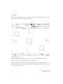
User Guide
iGrafx IDEF0® 2009 User Guide
The contents of this iGrafx IDEF0 user guide and the associated iGrafx IDEF0 software are the property
of Corel Corporation and its respective licensors, and are protected by copyright. Any reproduction in
whole or in part is strictly prohibited. For more complete copyright information about iGrafx IDEF0,
please refer to the About iGrafx section in the Help menu of the software.
© 2009 Corel Corporation. All rights reserved. iGrafx®, iGrafx FlowCharter™, iGrafx®
Process™, iGrafx® Process™ for Six Sigma, iGrafx® Process™ for Enterprise Modeler®, iGrafx
IDEF0®, iGrafx® Process Central™, iGrafx® Enterprise Central™, and iGrafx® Enterprise
Modeler® are all trademarks or registered trademarks of Corel Corporation and/or its
subsidiaries in Canada, the U.S. and/or other countries. Microsoft and Windows are trademarks
or registered trademarks of Microsoft Corporation in the U.S. and/or other countries. Adobe,
Acrobat, and Reader are registered trademarks of Adobe systems Incorporated in the United
States and/or other countries. Java and JavaScript are trademarks of Sun Microsystems, Inc.
Other product, font, and company names and logos may be trademarks or registered trademarks
of their respective companies.
Microsoft SQL Server 2005© Copyright 2005, Microsoft Corporation. All rights reserved.
AIAG Tables 2, 3, and 4 from Chao, L.P., and Ishii, K., (2004), “Challenges and Methods in the
Quantification of Design Errors and Solution Elements,” Proceedings of the ASME International
Mechanical Engineering Congress and Exposition, November 2004, Anaheim, CA.
IMECE2004-59190, © 2004 ASME, used with permission by ASME.
Rev: March 2, 2009
Table of Contents
Introduction . . . . . . . . . . . . . . . . . . . . . . . . . . . . . . . . . . . . . . . . . . . . . . . . . . . . . . . . . . . . 3
The IDEF0 Modeling Language . . . . . . . . . . . . . . . . . . . . . . . . . . . . . . . . . . . . . . . . . . .
The IDEF0 Notation . . . . . . . . . . . . . . . . . . . . . . . . . . . . . . . . . . . . . . . . . . . . . . . .
IDEF0 Models . . . . . . . . . . . . . . . . . . . . . . . . . . . . . . . . . . . . . . . . . . . . . . . . . . . . .
IDEF0 Diagrams . . . . . . . . . . . . . . . . . . . . . . . . . . . . . . . . . . . . . . . . . . . . . . . . . . . . . . .
Top-Level Context Diagram . . . . . . . . . . . . . . . . . . . . . . . . . . . . . . . . . . . . . . . . . .
Child Diagram . . . . . . . . . . . . . . . . . . . . . . . . . . . . . . . . . . . . . . . . . . . . . . . . . . . . .
Parent Diagram . . . . . . . . . . . . . . . . . . . . . . . . . . . . . . . . . . . . . . . . . . . . . . . . . . . .
Node Tree Diagram . . . . . . . . . . . . . . . . . . . . . . . . . . . . . . . . . . . . . . . . . . . . . . . . .
Text Diagram . . . . . . . . . . . . . . . . . . . . . . . . . . . . . . . . . . . . . . . . . . . . . . . . . . . . .
Glossary . . . . . . . . . . . . . . . . . . . . . . . . . . . . . . . . . . . . . . . . . . . . . . . . . . . . . . . . . .
For Exposition Only Diagram . . . . . . . . . . . . . . . . . . . . . . . . . . . . . . . . . . . . . . . . .
3
4
5
5
5
7
8
8
8
8
8
Creating an iGrafx IDEF0 Model . . . . . . . . . . . . . . . . . . . . . . . . . . . . . . . . . . . . . . . . . . . . . . 9
Start IDEF0. . . . . . . . . . . . . . . . . . . . . . . . . . . . . . . . . . . . . . . . . . . . . . . . . . . . . . . . . . . 9
Define the Model. . . . . . . . . . . . . . . . . . . . . . . . . . . . . . . . . . . . . . . . . . . . . . . . . . . . . . 10
Add Diagrams to Your Model . . . . . . . . . . . . . . . . . . . . . . . . . . . . . . . . . . . . . . . . . . . . 11
Add a Child Diagram . . . . . . . . . . . . . . . . . . . . . . . . . . . . . . . . . . . . . . . . . . . . . . 11
Add a FEO Diagram . . . . . . . . . . . . . . . . . . . . . . . . . . . . . . . . . . . . . . . . . . . . . . . 13
Add a Text Diagram . . . . . . . . . . . . . . . . . . . . . . . . . . . . . . . . . . . . . . . . . . . . . . . 14
Editing an iGrafx IDEF0 Model . . . . . . . . . . . . . . . . . . . . . . . . . . . . . . . . . . . . . . . . . . . . . . 15
Change Properties . . . . . . . . . . . . . . . . . . . . . . . . . . . . . . . . . . . . . . . . . . . . . . . . . . . . .
Change ICOM Labels . . . . . . . . . . . . . . . . . . . . . . . . . . . . . . . . . . . . . . . . . . . . . .
Work with Model Templates . . . . . . . . . . . . . . . . . . . . . . . . . . . . . . . . . . . . . . . . . . . .
Edit a Model Template . . . . . . . . . . . . . . . . . . . . . . . . . . . . . . . . . . . . . . . . . . . . .
Create a Model Template . . . . . . . . . . . . . . . . . . . . . . . . . . . . . . . . . . . . . . . . . . . .
Customize Text and the Glossary . . . . . . . . . . . . . . . . . . . . . . . . . . . . . . . . . . . . . . . . .
Validate a Model . . . . . . . . . . . . . . . . . . . . . . . . . . . . . . . . . . . . . . . . . . . . . . . . . .
Print IDEF0 Models . . . . . . . . . . . . . . . . . . . . . . . . . . . . . . . . . . . . . . . . . . . . . . .
15
16
16
16
17
20
25
26
Using iGrafx IDEF0 Menus and Tools . . . . . . . . . . . . . . . . . . . . . . . . . . . . . . . . . . . . . . . . . 29
Menus . . . . . . . . . . . . . . . . . . . . . . . . . . . . . . . . . . . . . . . . . . . . . . . . . . . . . . . . . . . . . . 29
Diagram Context Menu . . . . . . . . . . . . . . . . . . . . . . . . . . . . . . . . . . . . . . . . . . . . . 30
Shape Context Menu . . . . . . . . . . . . . . . . . . . . . . . . . . . . . . . . . . . . . . . . . . . . . . . 31
iGrafx IDEF0 2009 User Guide
1
iGrafx IDEF0 Tools . . . . . . . . . . . . . . . . . . . . . . . . . . . . . . . . . . . . . . . . . . . . . . . . . . . 31
The IDEF0 Model Setup Wizard . . . . . . . . . . . . . . . . . . . . . . . . . . . . . . . . . . . . . . 32
The IDEF Explorer . . . . . . . . . . . . . . . . . . . . . . . . . . . . . . . . . . . . . . . . . . . . . . . . . 33
The IDEF Rules Validator . . . . . . . . . . . . . . . . . . . . . . . . . . . . . . . . . . . . . . . . . . . 35
The IDEF0 Toolbar . . . . . . . . . . . . . . . . . . . . . . . . . . . . . . . . . . . . . . . . . . . . . . . . 36
IDEF0 Model Templates . . . . . . . . . . . . . . . . . . . . . . . . . . . . . . . . . . . . . . . . . . . . 37
2
iGrafx IDEF0 2009 User Guide
Introduction
1
iGrafx IDEF0® is a custom add-on to iGrafx® that lets you build business process models
based on the Integration Definition language 0 (IDEF0).
This language is defined by the Integration Definition for Function Modeling (IDEF0)
Standard issued by the Federal Information Processing Standards Publications (FIPS PUBS)
on December 21, 1993.
System requirements are published in the release notes and on the iGrafx IDEF0 product
page under FAQs.
iGrafx IDEF0 Features
iGrafx IDEF0 gives you the following capabilities:
•
IDEF0 Model Setup Wizard- The Model Wizard prompts you for model and diagram
properties when adding a new model to a document.
•
IDEF Rules Enforcement- IDEF0 uses correct-by-design and rules checking
technology to insure the accuracy and consistency of your model.
•
IDEF Explorer- The Explorer lets you navigate the components of a model.
•
Associated Components- iGrafx IDEF0 lets you add components to models such as
FEO diagrams, text diagrams, and glossaries.
•
IDEF0 Model Templates- You can use model templates to help build models.
The IDEF0 Modeling Language
The IDEF0 modeling language is a graphics and text based notation used to model a system
or process. An IDEF0 model is composed of a hierarchical series of diagrams that gradually
display increasing levels of detail within the context of a process.
Introduction
3
The IDEF0 Notation
The IDEF0 notation consists of boxes and arrows. Boxes represent the activities of a process
while arrows represent data or objects related to each activity.
IDEF0 Activities
You give each activity a name, usually a verb-noun phrase such as plan project or conduct
review. Activity boxes also include a number in the lower right-hand corner of the box. This
number is a Detail Reference Expression (DRE) indicating the relative position of the
activity within the diagram hierarchy.
Arrows enter and exit each activity box and represent Inputs, Control, Outputs, and
Mechanisms (ICOM). Each arrow is labeled to describe the data or object it represents.
Arrow
Purpose
Inputs
Enter boxes from the left and represent data or objects transformed or
consumed by the function to produce outputs.
Controls
Enter activities from the top and represent the conditions required for
the function to produce correct outputs.
Outputs
Exit activities to the right and represent data or objects produced by the
function.
Mechanisms
Enter activities from the bottom and identifies some of the means that
support the execution of the function.
4
iGrafx IDEF0 2009 User Guide
IDEF0 Models
IDEF0 models include three types of diagrams: graphic diagrams, text, and glossary. These
diagrams cross-reference each other. The graphic diagram is the major component of an
IDEF0 model containing boxes, arrows, box/arrow interconnections, and associated
relationships.
The top-level diagram in the model provides the most general or abstract description of the
subject represented by the model. This diagram is followed by a series of child diagrams
providing more detail about the subject.
IDEF0 Diagrams
IDEF0 models include three types of diagrams: graphic diagrams, text, and glossary.
Graphic diagrams include the top-level context diagram, parent/child diagrams, FEO
diagrams, and the Node Tree diagram.
Top-Level Context Diagram
The top-level context diagram, also called the A-0 diagram (pronounced A minus zero), is a
graphics diagram representing the entire system or process as a single box with bounding
arrows. The A-0 diagram sets the model scope or boundary and orientation of the process.
Introduction
5
The arrows on this diagram represent data or objects outside the process and are the
complete set of external interfaces to the process.
Example Top-Level Context Diagram
The A-0 diagram also includes a statement of the diagrams purpose and viewpoint. The
statement of purpose expresses the reason why the model is created, and viewpoint describes
the perspective from which you view the model.
6
iGrafx IDEF0 2009 User Guide
Child Diagram
You can decompose the single function represented on the top-level context diagram into
subfunctions by creating its child diagram. You can also decompose each of these child
diagrams into subfunctions by creating lower-level child diagrams.
A Child Diagram
The child diagram that results from the decomposition of a function covers the same scope
as the parent box it details. Thus, you can think of a child diagram as being inside its parent
box.
Introduction
7
Parent Diagram
Any diagram that has a child diagram is a parent diagram. Thus a diagram may be both a
parent diagram (containing parent boxes) and a child diagram (detailing its own parent
box). Likewise, a box may be both a parent box (detailed by a child diagram) and a child box
(appearing on a child diagram).
The fact that a child box is detailed, and is therefore also a parent box, is indicated by the
presence of a Detail Reference Expression (DRE). The DRE is a short code written below the
lower right corner of the detailed (parent) box that points to its child diagram.
Node Tree Diagram
A node tree diagram is a graphics diagram showing the relationship between parent and
child activities as a hierarchical tree. Each activity in your model is represented by a node on
the tree.
Text Diagram
You can associate text with a diagram by creating a text diagram. Use text to highlight
features, flows, and inter-box connections to clarify the intent of items and patterns.
Glossary
You can create a glossary for each graphic diagram in your mode. Each glossary defines text
that appears on the diagram such as acronyms and key words and phrases used in
conjunction with diagram graphics. The glossary defines words in the model that convey a
common understanding to correctly interpret the model content.
For Exposition Only Diagram
For Exposition Only (FEO, pronounced fee-oh) diagrams are free-form diagrams (i.e., they
need not comply with IDEF0 syntax rules) that provide an additional level of
supplementary knowledge for specific areas of a model.
8
iGrafx IDEF0 2009 User Guide
Creating an iGrafx IDEF0 Model
2
The first step in creating an iGrafx IDEF0 model is to start the IDEF0 application and use
the Model Setup Wizard to define your model.
Start IDEF0
iGrafx IDEF0 treats an IDEF0 model as another iGrafx document type. Therefore, you can
start IDEF0 from iGrafx using the Welcome dialog box, the New command, or the From Template
command.
Start from iGrafx
On the iGrafx File menu, point to New and choose IDEF0 (A-0). You can define the basic
characteristics of a model from the Model Setup Wizard that appears.
Start from the Welcome dialog box
1 On the Windows Start menu, point to iGrafx and choose Flowcharter or Process.
2 In the Welcome dialog box, click New Document, and click IDEF0 (A-0).
Start from a Template
1 On the File menu, point to New and choose From Template.
2 In the New dialog box, click the IDEF0 tab.
3 Select a template from the template list, and click OK.
Creating an iGrafx IDEF0 Model
9
Define the Model
When you start a new IDEF0 document, the Model Setup Wizard opens automatically. The
information you enter through the Model Setup Wizard defines the complete A-0 diagram
for your model.
Define an A-0 Diagram
1 In the Model Setup Wizard, click Next.
2 In the Setup Data dialog box, type the model name, function, purpose, and viewpoint.
3 Click Select Template.
4 Use the Template Browser in the Template Browser dialog box to locate and select a
template, and click OK.
5 Click Next.
6 In the Input dialog box, click Add and type the name of a model input in the Input
box.
Repeat step 7 for each input to your model. Click Rename to change the name
of any inputs. Click Delete to remove an input.
7 Click Next.
8 In the Control dialog box, type the name of a model control in the Control box.
Click Add to add additional controls. Click Rename to change the name of a
control. Click Delete to delete a control.
9 Click Next.
10 Type the name of a model output in the Output box.
11 Click Next.
10
iGrafx IDEF0 2009 User Guide
12 Click Add, and type the name of a model mechanism in the Mechanism box.
Repeat step 12 for each mechanism of your model. Click Rename to change the
name of any mechanism. Click Delete to remove a mechanism.
13 Click Next.
14 Click Finish. The IDEF0 Setup Wizard closes and displays the A-0 diagram for your
model.
Add Diagrams to Your Model
After you have defined a model, you are ready to add diagrams to it.
Add a Child Diagram
1 Right-click an activity in the diagram and choose Add Detailed Diagram on the context
menu.
or
On the IDEF0 menu, point to Add and choose Add Detailed Diagram.
2 Use the slide bar in the Create Detailed Diagram dialog box to specify the number of
activities in the child diagram.
Creating an iGrafx IDEF0 Model
11
3 Click OK.
You can create a child diagram for any activity in a process model. When you create a new
child diagram, a template for the diagram opens.
A Detailed Diagram
The new diagram contains the number of activities you specified. The activities are
unnamed, so you need to provide a name for each activity.
Notice that all of the arrows from the parent diagram appear on the child diagram.
However, they do not connect to any activity on the diagram. You must connect the arrows
to the appropriate activities.
12
iGrafx IDEF0 2009 User Guide
Also notice that there are no arrows between the activities of the child diagram. You must
add arrows to connect the activities. Such arrows typically represent the flow of data or
objects between the activities.
Name an Activity
1 Right-click an activity in the diagram and choose Activity Properties on the context menu.
or
On the IDEF0 menu, point to Current Model Properties and choose Activity Properties.
2 In the IDEF0 Options dialog box, click the Index tab.
3 Type an activity name in the Name text box.
4 Click OK.
Connect Arrows to an Activity
1 Place the cursor over an arrow.
2 Click and hold the left mouse button.
3 Drag the arrow until it intersects an activity.
4 Release the mouse button.
Add a FEO Diagram
Right-click a diagram and choose Add FEO Diagram on the context menu.
or
In the IDEF Explorer, right-click a diagram icon and choose Add FEO Diagram on the context
menu.
or
On the IDEF0 menu, point to Add and choose Add FEO Diagram.
Creating an iGrafx IDEF0 Model
13
Add a Node Tree Diagram
In the IDEF Explorer, right-click a Model icon and choose Add Node Tree on the context
menu.
or
On the IDEF0 menu, point to Add and choose Add Node Tree.
Add a Text Diagram
You can create a Text diagram for any activity in your process model. When you add a text
diagram, a text editor opens. The text editor is connected to the standard text formatting
toolbar for customizing a text diagram. To add a text diagram:
Right-click a diagram and choose Add Text Diagram on the context menu.
or
In the IDEF Explorer, right-click a diagram icon and choose Add Text Diagram on the context
menu.
or
On the IDEF0 menu, point to Add and choose Add Text Diagram.
Add a Glossary
1 Highlight the text in a graphic diagram that you would like to add to the glossary.
2 On the IDEF0 menu, point to Glossary and choose Add To Glossary.
3 In the Add Term dialog box, type a definition for the selected text in the Definition text
box, and click Add. A Glossary icon appears in the Explorer window. Click this icon to
view your new glossary entry.
14
iGrafx IDEF0 2009 User Guide
Editing an iGrafx IDEF0 Model
3
In addition to adding diagrams to your model, you can change model, diagram, activity, and
ICOM properties.
You can also add custom data fields and data groups, and customize text, glossaries, and
arrows.
Change Properties
You can change the name of your model, redefine the activity prefix character, and change
the DRE format. To change model properties:
1 Right-click a diagram and choose Model Properties on the context menu.
or
On the IDEF0 menu, point to Current Model Properties and choose Model Properties.
or
On the IDEF0 toolbar, click the Model Properties
tool.
2 In the Current IDEF0 Model Properties dialog box, click the Model tab, and type any
model property changes.
3 Click OK.
Editing an iGrafx IDEF0 Model
15
Change Diagram Properties
For each diagram in your model you can change the diagram name, specify the author and
readers of the diagram, enter revision dates, and set the current status of the diagram. To
change diagram properties:
1 Right-click a diagram and choose Diagram Properties on the context menu.
or
On the IDEF0 menu, point to Current Model Properties and choose Diagram Properties.
or
On the IDEF0 toolbar, click the Model Properties
tool.
2 In the Current IDEF0 Model Properties dialog box, click the Diagram tab, and type any
diagram property changes.
3 Click OK.
Change ICOM Labels
To rename an ICOM:
1 Double-click the line. The Arrow Name dialog box appears.
2 Use the Arrow Name dialog box to change the label.
3 Click OK.
Work with Model Templates
You can customize the template assigned to your model or you can create new templates.
Edit a Model Template
You can edit your model template to customize the look of your model. You can add a logo,
move lines, change field labels, and delete fields from your template. Edits made to the
template are propagated back to all existing diagrams in your model and are used in all new
diagrams added to the model.
Note that you cannot resize the drawing area of your template. To resize the drawing area,
you must create a new template.
16
iGrafx IDEF0 2009 User Guide
Create a Model Template
You can also create your own templates by editing the template file directly. To create a new
template, start with an existing template, make your customizations, and save the changes
under a new file name. In your new template, you can customize the following elements:
Element
Description
Print Frame
Area that encompasses all printed items when you use the Print
command. You can resize the print frame.
Resizing the print frame may cause unpredictable results. A better
approach is to resize the entire template.
Draw Frame
Area that contains the graphics for each diagram. You can resize the
draw frame to create a larger or smaller drawing area.
Frame
Area that contains headers and lines. You can add, edit, move, delete,
and change the fonts of headers, and add, move, delete, and change the
line style of lines in the frame.
A-0
Area that contains items appearing only on the top level context
diagram of your model. Typically, this includes the model purpose and
viewpoint. You can add or remove items from this area. Items added to
the area appear only in the A-0 diagram of your model.
Fields
Area that contains the text fields for your model. You can move or
delete fields.
Customize the Fields of Your Template
1 On the IDEF0 menu, choose Edit Template.
2 In the Template Editor dialog box, click the Fields tab at the bottom of the template
diagram.
3 Click a field in the template.
Fields begin with <<. For example, the Author field is <<Author and appear
as layer tabs at the bottom of the diagram.
Editing an iGrafx IDEF0 Model
17
4 Delete the selected field, drag it to a new location, or double-click the field to edit the
field name.
5 Click Apply.
6 Click Done.
Customize the Frame of Your Template
1 On the IDEF0 menu, choose Edit Template.
2 In the Template Editor dialog box, click the Frame tab at the bottom of the template
3
4
5
6
diagram.
Click a frame item in the template.
Delete the selected frame item, drag it to a new location, or resize it.
Click Apply.
Click Done.
Create a New Template
1 On the File menu, choose Open.
Template files have the suffix .IGT. You can find templates supplied with IDEF0
at \Program Files\iGrafx\Pro\13.0\Template\1033\Idef0.
2 In the Open dialog box, click iGrafx Template in the Files of type list.
3 Double-click an IDEF0 template file.
4 On the File menu, choose Save As to save your template under a new template name.
When prompted, click No to place the new template in the IDEF0 template
directory. Click YES to place it in the default template directory.
18
iGrafx IDEF0 2009 User Guide
Customize the Print Frame
1 On the File menu, choose Open.
2 In the Open dialog box, click iGrafx Template in the Files of type list.
3 Double-click an IDEF0 template file to open it.
4 Click the <<PrintFrame tab.
5 Click the print frame.
6 Click the Zoom Control
tool on the Standard toolbar and set the view to a
small enough percentage to see the outside of the print frame (typically the outer
rectangle of the template).
7 Resize the print frame.
8 On the File menu, choose Save As to save your template under a new template name.
Customize the Draw Frame
1 On the File menu, choose Open.
2 In the Open dialog box, click iGrafx Template in the Files of type list.
3 Double-click an IDEF0 template file to open it.
4 Click the <<DrawFrame tab.
5 Click the draw frame (typically the inner rectangle of the template).
6 Click theZoom Control
tool on the Standard toolbar and set the view to a
small enough percentage to see the outside of the draw frame.
7 Resize the draw frame.
8 On the File menu, choose Save As to save your template under a new template name.
Customize the Frame
1 On the File menu, choose Open.
2 In the Open dialog box, click iGrafx Template in the Files of type list.
3 Double-click an IDEF0 template file to open it.
4 Click the Frame tab.
5 Select and customize lines or headers in the frame.
6 On the File menu, choose Save As to save your template under a new template name.
Editing an iGrafx IDEF0 Model
19
Customize the A-0 Diagram
1 On the File menu, choose Open.
2 In the Open dialog box, click iGrafx Template in the Files of type list.
3 Double-click an IDEF0 template file to open it.
4 Click the A-0 tab.
5 Make desired changes to the A-0 area.
6 On the File menu, choose Save As to save your template under a new template name.
Create New Field Name Objects
1 Click the Draw
2
3
4
5
6
tool on the Draw toolbar, and click Rectangle.
Draw a rectangle for the size of the field you want.
Right-click the rectangle and choose Format on the context menu.
In the Format Graphic dialog box, click the None Fill Style option, and click OK.
Double-click inside the rectangle to add text.
Type a field name. You can only type one of the valid field names provided by IDEF0
(see IDEF0 Model Templates on page 37).
Customize Fields
1 On the File menu, choose Open.
2 In the Open dialog box, click iGrafx Template in the Files of type list.
3 Double-click an IDEF0 template file to open it.
4 Click the Fields tab.
5 Click fields to edit, delete, move, or customize fonts.
6 On the File menu, choose Save As to save your template under a new template name.
Customize Text and the Glossary
You can add text to your diagram and customize your model’s glossary by adding new
terms, removing terms, modifying the definition of any term in the glossary, and
20
iGrafx IDEF0 2009 User Guide
reanchoring terms. IDEF0 also lets you check the spelling of any term and definition in your
glossary.
Add text to a diagram
1 In the IDEF Explorer window, double-click a text diagram
icon.
2 In the text diagram, type any text necessary to describe the
diagram.
View Text For a Diagram In the IDEF Explorer window, double-click a text diagram icon.
Change Font Properties
1 On the IDEF0 menu, point to Current Model Properties and
choose Font Properties.
2 Click a text category from the Category list, and click
Choose Font.
3 Make any font changes in the Font dialog box, and click
OK.
4 Click OK to close the Properties dialog box.
Add Terms To a Glossary 1 Highlight the text in the graphic diagram that you want to
add as a glossary term.
2 On the IDEF0 menu, point to Glossary and choose Add To
Glossary.
3 In the New Glossary Entry dialog box, type a definition for
the selected text in the Definition text box.
4 Click Add.
Remove Terms From a
Glossary Using the
IDEF0 Menu
1 Highlight the text in the graphic diagram that you would
Remove Terms From a
Glossary Using the
IDEF Explorer
1 In the IDEF Explorer window, double-click a glossary icon.
like to remove from the glossary terms.
2 On the IDEF0 menu, point to Glossary and choose Delete
Glossary Entry.
2 On the IDEF0 menu, point to Glossary and choose Modify
Glossary.
3 In the Edit Glossary Definitions dialog box, click a term
from the Term list, and click Delete.
Editing an iGrafx IDEF0 Model
21
Modify Terms In a
Glossary Using the
IDEF0 Menu
1 Highlight the text in a graphic diagram that you would
Modify Terms In a
Glossary Using the
IDEF Explorer
1 In the IDEF Explorer window, double-click a glossary icon.
like to modify the glossary term for.
2 On the IDEF0 menu, point to Glossary and choose Modify
Glossary Definition.
3 In the New Glossary Entry dialog box, type a new
definition for the term in the Definition text box.
4 Click Add.
2 On the IDEF0 menu, point to Glossary and choose Modify
Glossary.
3 In the Edit Glossary Definitions dialog box, click a term in
the Term list.
4 In the Definition text box, type a new definition for the
term. (You can click Reset to set the term back to its
original definition.)
5 Click Apply.
Check the Spelling of
Terms in a Glossary
1 In the IDEF Explorer window, double-click a glossary icon.
2 On the IDEF0 menu, point to Glossary and choose Modify
Glossary.
3 In the Edit Glossary Definitions dialog box, click a term in
the Term list.
4 Click Check Spelling.
or
Click Check Spelling in all Definitions.
22
iGrafx IDEF0 2009 User Guide
Arrows
Arrows are used to represent the flow of data or objects in your model. You can add arrows
to your model, remove arrows from your model, or tunnel the display of arrows.
Add Arrows
Typically, you add new arrows to connect activities of detailed diagrams. However, you can
also add arrows to parent diagrams. Arrows added to parent diagrams appear in the
corresponding detailed diagrams. To draw a new arrow to an activity:
1 On the Toolbox toolbar, click the Connector Line
tool.
2 Locate the cursor in a blank area of the diagram.
3 Click and hold the left mouse button, and drag the arrow until it intersects an activity.
4 Release the mouse button.
5 In the Arrow Name dialog box, type a name in the Enter the Arrow Name text box.
6 Click OK.
If the activity has a detail diagram, the new arrow appears in the detail diagram.
Draw a New Arrow Between Activities
1 On the Toolbox toolbar, click the Connector Line
tool.
2 Locate the cursor over an activity.
3 Click and hold the left mouse button, and drag the arrow until it intersects an activity.
4 Release the mouse button.
5 In the Arrow Name dialog box, type a name in the Enter the Arrow Name text box.
6 Click OK.
Editing an iGrafx IDEF0 Model
23
Delete Arrows
If you choose to delete an arrow that appears at more than one level of your model, you can
choose to delete the arrow completely from your model or to tunnel the arrow (see Tunnel
Arrows). To delete an arrow:
1 Click an arrow.
2 On the Edit menu, choose Cut.
or
On the Standard toolbar, click the Cut tool.
3 If the arrow appears at more than one level of your model, the Resolve Arrow dialog
box opens.
4 Click Delete.
5 Click OK.
Tunnel Arrows
Tunneled arrows are arrows with special notations that indicate that the arrows do not
appear at all levels of the model.
For example, on a parent diagram you can select an arrow and tunnel it at the point it is
connected to an activity box. An arrow tunneled at the point it is connected to an activity
box means the arrow is not necessary for understanding the detail diagram for activity. The
tunneled arrow is deleted from the activities’ detail diagram and all subsequent
decompositions of the activity.
On a child diagram, you can draw an arrow and connect it to an activity box. The arrow is
shown tunneled at the unconnected end. An arrow tunneled at the unconnected end means
that the arrow is not necessary for understanding at the parent level and is not shown
connected to the parent box.
On a parent diagram, you can select an arrow and detach it from an activity box or delete it.
If the activity box is detailed, you are asked if you want to delete the arrow from the child
diagram or tunnel the arrow in the child diagram at its unconnected end.
To tunnel an arrow, right-click an arrow and choose Tunnel Arrow Tail or Tunnel Arrow Head on
the context menu.
or
24
iGrafx IDEF0 2009 User Guide
Click an arrow, and click the Tunnel Arrow Tail
IDEF0 toolbar.
or Tunnel Arrow Head
tool on the
Validate a Model
You can use the IDEF Rules Validator (see The IDEF Rules Validator on page 35) to check the
adherence of your model to the IDEF0 modeling rules.
Set the IDEF Rules Validator Properties
You can set the IDEF Rules Validator properties to check for any, all, or none of the
modeling rules. To set IDEF Rules Validator properties:
1 On the IDEF0 menu, point to Current Model Properties and choose Rules Properties. The
Current Model Properties dialog box opens with the Rules tab selected.
2 In the Design area, select the appropriate check boxes for specific design rules.
or
Click Select All to select all design rules.
or
Click Clear All to turn off design rule validation.
3 In the Validator area, select the appropriate check boxes for specific validator rules.
or
Click Select All to select all validator rules.
or
Click Clear All to turn off validator rules.
4 Click OK.
Editing an iGrafx IDEF0 Model
25
View the IDEF Rules Validator
Rules violations appear automatically in the IDEF Rules Validator window when it is open
at the bottom of your diagram. When you correct a rules violation, it disappears from the
window. You may need to refresh the window periodically to insure that an accurate set of
violations is displayed. To view the IDEF Rules Validator:
On the IDEF0 menu, point to IDEF Rules Options and choose IDEF Rules Validator.
or
On the IDEF0 toolbar, click the Rules Validator
tool.
Refresh the IDEF Rules Validator Window
On the IDEF0 menu, point to IDEF Rules Options and choose Refresh Rules Validator.
or
On the IDEF0 toolbar, click the Refresh Rules Validator
tool.
Print IDEF0 Models
You can print the active window of your model or the entire document. If the active window
is more than one page long, you can print a range of pages.
When you print the entire document, all parts of your model are printed including nonIDEF0 components. Printing the entire document also updates the page numbering for
IDEF0 components.
Print Your Model
1 On the IDEF0 menu, choose Print Model.
or
Click an icon in the IDEF Explorer, and choose Print Model on the context menu. The
Print Model dialog box opens.
2 In the Choose Components to Print area, select the appropriate check boxes for specific
printing items.
or
26
iGrafx IDEF0 2009 User Guide
Click Select All to select all components.
or
Click Clear All to deselect all components.
3 Click a printer in the Printers list.
4 Click OK.
Preview Your Model
You can preview the currently active window of your model prior to printing. Only the
active window can be previewed.
1 On the File menu, choose Print Preview. A preview of the currently active window opens.
2 Click Close to dismiss the preview.
Print to a Different Page Size or Orientation
To change the page size or orientation of your model printout, you must edit your model
template.
1 On he IDEF0 menu, choose Edit Templates. The Template Editor dialog box opens.
2 On the File menu, choose Page Setup. The Page Setup dialog box opens.
3 Choose the desired orientation and page size and click OK.
4 In the Template Editor dialog box, click Done.
5 On the IDEF0 menu, choose Print Model.
or
Click an icon in the IDEF Explorer, and choose Print Model on the context menu. The
Print Model dialog box opens.
6 In the Choose Components to Print, area select the appropriate check boxes for printing
items.
or
Click Select All to select all components.
or
Click Clear All to deselect all components.
7 Click a printer in the Printers list.
8 Click OK.
Editing an iGrafx IDEF0 Model
27
28
iGrafx IDEF0 2009 User Guide
Using iGrafx IDEF0 Menus and Tools
4
iGrafx IDEF0 uses menus and toolbars to provide much of its functionality.
Menus
Several menus and their corresponding commands exist for creating, editing, and refreshing
IDEF0 models.
IDEF0 Menu
The IDEF0 menu appears on the main menu bar when you create a new IDEF0 document.
The IDEF0 menu commands display windows, refresh windows, go to diagrams, add
detailed diagrams, and change model properties.
IDEF0 Menu
Commands
Description
Add
Displays a submenu of commands for adding diagrams to your
model (see Add Diagrams to Your Model). You can also add a
table of contents, and a node tree to a model using the Add
command.
Refresh
Displays a submenu of commands for refreshing the display of
certain IDEF0 windows, diagrams, and page numbers.
Go To
Displays a submenu of commands for displaying different
diagrams in your model.
Glossary
Displays a submenu of commands for creating and editing your
glossary.
Using iGrafx IDEF0 Menus and Tools
29
IDEF0 Menu
Commands
Description
Model Properties
Displays a submenu of commands for customizing your model,
diagram, activity, rule, and font properties (see Change
Properties)
Edit Model Page
Template
Opens the Template Editor.
Save Model as Webpage Lets you save your model to a specified directory in HTML
format.
Print Model
Lets you print your model.
IDEF Explorer Options Displays a submenu of commands for changing the display of the
IDEF Explorer.
IDEF Rules Options
Displays a submenu of commands for changing the display of the
IDEF Rules Validator (see Set the IDEF Rules Validator
Properties).
Diagram Context Menu
The diagram context menu appears when you right-click the diagram outside of any
diagram shape. The diagram context menu contains commands for viewing the glossary,
adding FE0 diagrams, adding detailed diagrams, viewing FE0 diagrams, and viewing or
changing model properties.
Diagram Menu
Commands
Description
Add Text
Diagram
Adds a text diagram to the current diagram.
Add FE0 diagram Adds an FE0 diagram to the current diagram.
Diagram
Properties
Changes the properties of the current diagram.
Model Properties Views and changes the model properties.
30
iGrafx IDEF0 2009 User Guide
Shape Context Menu
The shape context menu appears when you right-click an activity in a model. The shape
context menu contains commands for cutting, copying, or adding Detailed diagrams,
viewing or changing model properties, and editing a glossary.
Shape Context Menu
Commands
Description
Cut Detailed Diagram
Deletes the detailed diagram for the currently selected
activity.
Copy Detailed Diagram Copies the detailed diagram for the currently selected
activity.
Paste Detailed Diagram Pastes the detailed diagram from the Clipboard.
Add Detailed Diagram
Adds a detailed diagram to the currently selected activity.
Add Process
Opens the New Component dialog box for adding a new
process.
Activity Properties
Changes the properties of the currently selected activity.
Modify Glossary
Definition
Modifies the glossary entry for the current activity.
Add to Glossary
Adds a definition for the current activity to the Glossary.
Delete Glossary Entry
Deletes the glossary entry for the current activity.
iGrafx IDEF0 Tools
iGrafx IDEF0 also provides several tools for creating, editing, and verifying your IDEF0
model.
Using iGrafx IDEF0 Menus and Tools
31
The IDEF0 Model Setup Wizard
The Model Setup Wizard is a series of dialogs that let you define the following
characteristics of a model:
•
Model Name
•
Model Function
•
Model Purpose
•
Model Viewpoint
•
Template
•
Inputs
•
Outputs
•
Controls
•
Mechanism
The Model Setup Wizard starts automatically when you create a new IDEF0 document.
The information you enter using the Wizard defines the A-0 diagram for your model.
32
iGrafx IDEF0 2009 User Guide
The IDEF Explorer
The IDEF Explorer is a dialog box that lets you navigate through the components of your
model. The Explorer appears automatically when you create a new model. You can turn the
Explorer display on or off using the IDEF0 menu.
IDEF Explorer
With the Explorer you can view, add, rename, delete, print, and change the properties of the
components of your model. You can also right-click in the Explorer window and click Copy
Explorer to place a text object of the current view on the Clipboard.
The components of a model appear as labeled icons in the Explorer window.
Using iGrafx IDEF0 Menus and Tools
33
Explorer
Icons
Purpose
The top-level icon for the model.
Represents the A-0 diagram.
Represents an FEO diagram.
Represents a detailed diagram.
Represents an activity.
Represents a table of contents (TOC).
Represents a node tree diagram.
Represents a text diagram.
Represents a glossary.
To view a component such as a diagram or glossary, double-click its icon in the Explorer
window. To perform a command on a component, right-click the icon and select a command
on the context menu.
34
iGrafx IDEF0 2009 User Guide
The IDEF Rules Validator
The IDEF Rules Validator displays any syntax or semantic rule’s violations for the IDEF0
notation in your model. The Rules Validator displays the diagram name, activity, and error
description for each error that occurs in a model.
Rules Validator
You can toggle the display of the IDEF Rules Validator using the IDEF0 menu.
Using iGrafx IDEF0 Menus and Tools
35
The IDEF0 Toolbar
The IDEF0 toolbar contains tools for each command found in the IDEF0 main menu. You
can toggle the display of the toolbar using the View menu.
Tools
Purpose
Toggles the display in the IDEF Explorer window on or
off.
Toggles the display in the IDEF Rules Validator window
on or off.
Opens the Model Properties dialog box.
Refreshes the display of the IDEF Rules Validator
window.
Refreshes the display of all windows.
Switches the display to the parent activity of the detailed
diagram.
Switches the display to the detailed diagram for the
currently selected activity.
Creates a detailed diagram for the currently selected
activity.
Shows the callout squiggle line. The squiggle callout on a
line is the only valid callout in an IDEF diagram. The
callout squiggle line attaches the line label to the line.
Shows a tunnel at the tail of an arrow.
Shows a tunnel at the head of an arrow.
Straighten the edge of an arrow.
36
iGrafx IDEF0 2009 User Guide
IDEF0 Model Templates
IDEF0 provides several model templates that for creating a model. A template is an iGrafx
FlowCharter/Process document containing an IDEF0 diagram. This diagram contains
special graphics objects with text labels that identify what data is displayed in the object.
Each label begins with << followed by a text descriptor. For example, the labels
<<PrintFrame and <<DrawFrame describe the drawing area of the document.
Labels such as <<Author and <<Model describe replaceable text for the author name and
model name.
Using iGrafx IDEF0 Menus and Tools
37
Field Name
Purpose
<<Used At
Used At
<<Author
Author Name
<<Model
Model Name
<<CreateDate
Creation Date
<<RevDate
Revision Date
<<W
Working Status Date
<<D
Draft Status Box
<<R
Recommended Status Box
<<P
Publication Status Box
<<Reader1
Reader 1 Name
<<Reader2
Reader 2 Name
<<Reader3
Reader 3 Name
<<Date1
Reader 1 Date
<<Date2
Reader 2 Date
<<Date3
Reader 3 Date
<<ContextFrame Defines the context box location
<<Parent Node
Parent Node Name
<<Node
Current Node Name
<<Activity
Activity Name
<<CNumber
C-Number
38
iGrafx IDEF0 2009 User Guide
Field Name
Purpose
<<Pg
Page Number
<<Purpose
Purpose
<<ViewPoint
Viewpoint
iGrafx IDEF0 ships with a number of templates based on page size. For example, there are
templates that generate models in Letter size and A4 size.
Select a template when first creating a model (see Start IDEF0). After creating a model, you
can edit the template to customize the look of the diagram (see Work with Model
Templates).
You can also create your own templates by editing the template file directly (see Create a
Model Template).
Using iGrafx IDEF0 Menus and Tools
39
40
iGrafx IDEF0 2009 User Guide
Index
A
A-0 diagrams 5
customize 20
define 10
Activities
connect arrows to 13
draw arrows between 23
draw arrows to 23
name 13
Add a glossary 14
Add a text diagram 14
Add child diagrams 11
Add FEO diagrams 13
Add glossary terms 21
Add Node Tree diagrams 14
Add text to a diagram 21
Arrows 4
connect to activities 13
delete 24
draw between activities 23
draw to activities 23
tunnel 24
types 23
Customize frames 19
Customize print frames 19
Customize template fields 17
Customize template frames 18
Customizie A-0 diagrams 20
D
Define A-0 diagrams 10
Delete arrows 24
Detail Reference Expression 4
Diagram Context menu 30
Diagram properties, change 16
Diagrams
A-0 5
add text 21
Child 7
For Exposition Only (FEO) 8
Node Tree 8
Parent 8
Text 8
Top-Level Context 5
view text 21
Draw Frames, customize 19
C
Change diagram properties 16
Change font properties 21
Change ICOM labels 16
Changing
model properties 15
Child diagrams 7
add 11
Create field name objects 20
Create model templates 18
Customize draw frames 19
Customize fields 20
iGrafx IDEF0 2009 User Guide
E
Expressions 4
F
Field name objects, create 20
Fields
customize 20
customize for templates 17
41
Font properties, change 21
For Exposition Only diagrams (FEO)
about 8
add 13
Frames
customize 19
customize for templates 18
G
Glossary 8
add 14
add terms 21
modify terms using the IDEF Explorer 22
modify terms using the IDEFO menu 22
remove terms using the IDEF Explorer 21
remove terms using the IDEFO menu 21
spell check 22
I
ICOM
change name 16
change properties 16
IDEF Explorer
copy the current view to the clipboard 33
modify glossary terms 22
remove glossary terms 21
IDEF Rules Validator
refresh the window 26
set properties 25
view 26
IDEF0
Explorer 33
Menu 29
modeling language 3
notation 4
toolbar 36
IDEFO menu
modify glossary terms 22
42
remove glossary terms 21
M
Menus
Diagram Context 30
IDEF0 29
Shape Context 31
Model properties, changing 15
Model Setup Wizard 32
Model Templates 37
create 18
customize 16
customize fields 17
customize frames 18
Model Validation 25
Modeling Language 3
Models
preview 27
N
Name an activity 13
Node Tree diagrams 8
add 14
Notation 4
P
Parent diagrams 8
Preview models 27
Print Frames
customize 19
iGrafx IDEF0 2009 User Guide
R
rename ICOM 16
Rules Validator, IDEF 35
S
Shape Context menu 31
Spell check glossary terms 22
Start from a template 9
Start from iGrafx 9
Start from the Welcome dialog 9
T
Templates 9
create 18
customize fields 17
customize frames 18
Text diagram
add 14
Text diagrams 8
Text, add a diagram 14
Toolbars, IDEFO 36
Top-Level Context diagrams 5
add 10
Tunnel arrows 24
V
View diagram text 21
W
Welcome dialog 9
iGrafx IDEF0 2009 User Guide
43
44
iGrafx IDEF0 2009 User Guide