1
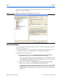
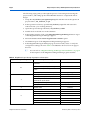
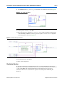
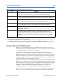
Megafunction Overview User Guide
© February 2009
UG-01056-1.0
Introduction
Megafunctions are vendor-specific intellectual property (IP) blocks that are parameterizable
and optimized for Altera® device architectures. Altera provides a library of megafunctions,
including the Library of Parameterized Modules (LPM) functions and other parameterized
functions, which offer more efficient logic synthesis and device implementation.
f
For more information about a particular megafunction, refer to the user guide of the
specific megafunction in the Literature: User Guides section of the Altera website.
f
For the latest list of available megafunctions and LPMs, refer to the Megafunctions or
the LPM section in the Quartus® II Help.
Overview
The MegaWizard™ Plug-In Manager allows you to create and modify design files that
contain custom megafunction variations, which you can then instantiate in a design file.
These custom megafunction variations are based on Altera-provided megafunctions. You
can use the MegaWizard Plug-In Manager to create Altera megafunctions, LPM functions,
and IP functions for use in designs in the Quartus II software, the EDA design entry, and
synthesis tools.
You can start the MegaWizard Plug-In Manager from the Quartus II software through one of
the following ways:
■
On the Tools menu, click MegaWizard Plug-In Manager.
■
When working in the Block Editor, from the Edit menu, click Insert Symbol Block, or
right-click in the Block Editor, point to Insert, and click Symbol as Block. In the Symbol
window, click MegaWizard Plug-In Manager.
■
Start the stand-alone version of the MegaWizard Plug-In Manager by typing the
following command at the command prompt:
qmegawiz r
■
© February 2009
In Windows, go to All Programs in the Start menu, select Quartus II in the Altera folder,
and click Quartus II MegaWizard Plug-In Manager.
Altera Corporation
Megafunction Overview User Guide
Page 2
Introduction
Figure 1 shows the categories of megafunctions that are available from the
MegaWizard Plug-In Manager.
Figure 1. Categories of Megafunctions Available in the MegaWizard Plug-In Manager
Device Family Support
You can check the device families supported for a particular megafunction through
one of the following ways:
■
Quartus II Help file—The latest information about the device family support is
individually stated for each megafunction in the Quartus II Help file.
■
MegaWizard Plug-In Manager:
■
Select a megafunction from the Which megafunction would you like to
customize? list on page 2a of the MegaWizard Plug-In Manager.
The device families supported for that megafunction are automatically shown
in the Which device family will you be using? pull-down list on the similar
page of the MegaWizard Plug-In Manager.
■
Select a device family from the Which device family will you be using?
pull-down list on page 2a of the MegaWizard Plug-In Manager.
The megafunctions that are supported for that family are shown in the Which
megafunction would you like to customize? list on the similar page of the
MegaWizard Plug-In Manager. The device families that are not supported are
grayed out.
Megafunction Overview User Guide
© February 2009
Altera Corporation
Design Example: Creating a New Megafunction Using the Quartus II MegaWizard Plug-In Manager
Page 3
Design Example: Creating a New Megafunction Using the Quartus II
MegaWizard Plug-In Manager
This example uses the MegaWizard Plug-In Manager to create a new instance of the
ALTCLKCTRL megafunction, and then connect the instance with an existing ALTPLL
instance in the top-level design schematic. You can download the project archive of
this design example from the Literature: User Guides section of the Altera website.
The ALTCLKCTRL megafunction is a clock control block megafunction that acts as a
clock buffer that selects clock signals. There are four clock signals: global clocks,
regional clocks, dual regional clocks, and external clock paths.
Figure 2 shows a block diagram of an ALTCLKCTRL megafunction with four input
clock ports, an output enable port, a two-bit selector port, and an output port.
Figure 2. ALTCLKCTRL Megafunction Block Diagram
ena
inclk 3x
inclk 2x
outclk
inclk 1x
inclk 0x
clkselect[1..0]
Table 1 shows the clock source selection using the two-bit selector port.
Table 1. Clock Source Selection
1
Binary Value
Signal Selection
clkselect[1..0] = 00
inclk 0x
clkselect[1..0] = 01
inclk 1x
clkselect[1..0] = 10
inclk 2x
clkselect[1..0] = 11
inclk 3x
For more information about the ALTCLKCTRL megafunction, refer to the
ALTCLKCTRL Megafunction User Guide or the Quartus II Help.
In this example, the ALTPLL instance implements a phase-locked loop (PLL) that uses
100 MHz of input clock to generate two output clock signals of 50 MHz and 200 MHz.
The ALTCLKCTRL instance implements a clock selector that contains four clock input
ports, with two of the input ports connected to the output ports of the ALTPLL, and
another two ports connected to dedicated clock pins. This example uses a
Stratix III® EP3SE50F484C2 device.
© February 2009
Altera Corporation
Megafunction Overview User Guide
Page 4
Design Example: Creating a New Megafunction Using the Quartus II
The following steps guide you through the process of extracting and restoring the
project archive, and setting up the ALTCLKCTRL instance to complete the whole
design:
1. Unzip the mo_altclkctrl_DesignExample.zip file and then extract the Quartus II
project archive, mo_altclkctrl_ex.qar.
2. In the Quartus II software, open the mo_altclkctrl_ex.qar file and restore the
archive file into your working directory.
3. Open the top-level design schematic, mo_altclkctrl_ex.bdf.
4. Double-click on a blank area in the schematic.
5. In the Symbol window, click on the MegaWizard Plug-In Manager button. Page 1
of the MegaWizard Plug-In Manager appears.
6. Select the Create a new custom megafunction variation option.
7. Click Next. Page 2a of the MegaWizard Plug-In Manager appears.
8. In the MegaWizard Plug-In Manager page 2a and onwards, select or verify the
configuration settings shown in Table 2. Click Next to advance from one page to
the next.
1
You can refer to “MegaWizard Plug-In Manager Generated Files” on page 6
for descriptions of the MegaWizard Plug-In Manager generated files.
Table 2. MegaWizard Plug-In Manager Page Option and Description
MegaWizard Plug-In Manager Page
2a
Configuration Setting
Which megafunction would you like to
customize?
ALTCLKCTRL
Which device family will you be using?
Stratix III
Which type of output file do you want to
create?
AHDL
What name do you want for the output file?
‘mo_clkctrl_gclk’
How do you want to use the altclkctrl?
For global clock
How many clock inputs would you like?
3
Create ‘ena’ port to enable or disable the clock
network driven by this buffer
How do you want to register the ‘ena’ port?
4
5
Megafunction Overview User Guide
Value
4
Selected
Falling edge of input clock
Ensure glitch-free switchover implementation
Selected
Generate netlist
Selected
Variation file
Selected
AHDL Include file
Selected
VHDL component declaration file
Selected
Quartus II symbol file
Selected
Instantiation template file
Selected
Verilog HDL black-box file
Selected
Synthesis area and timing estimation netlist
Selected
© February 2009
Altera Corporation
Design Example: Creating a New Megafunction Using the Quartus II MegaWizard Plug-In Manager
Page 5
9. Click Finish. The mo_clkctrl_gclk module is now built as shown in Figure 3.
Figure 3. mo_clkctrl_gclk Module
10. In the Symbol window, click OK.
11. Move the mouse to align the mo_clkctrl_gclk symbol with the existing ports
in the altclkctrl_ex.bdf file. Click to place the symbol. You have now completed
your design file as shown in Figure 4.
Figure 4. Complete Design Schematics
12. On the File menu, click Save.
13. Run a full compilation.
Simulation Libraries
To properly simulate the generated design files, you must include the simulation
model file or files in your simulation tool. You can find the information about the file
or files in the EDA tab in the MegaWizard Plug-In Manager. The Quartus II
simulation libraries are located at the <Quartus II installed path>\eda\sim_lib
directory.
© February 2009
Altera Corporation
Megafunction Overview User Guide
Page 6
Instantiating Megafunctions in HDL Code
1
For designs coded in VHDL, the simulation model libraries (<library_name>.vhd or
<library_name>_atoms.vhd) contain functional descriptions or atom declarations, and
these simulation model libraries must be simulated together with PACK file
(<library_name>_pack.vhd) or COMPONENT file (<library_name>_components.vhd).
1
For LPM simulation models, use the 220model.vhd and 220pack.vhd files for designs
coded in VHDL, and the 220model.v file for designs coded in Verilog HDL. Both files
are written based on the LPM version 220 (EIA-IS103 October 1998).
Instantiating Megafunctions in HDL Code
You can use megafunctions by instantiating them in your HDL code with the
following methods:
■
“Instantiating Megafunctions Using the MegaWizard Plug-In Manager” on page 6.
You can use the MegaWizard Plug-In Manager to parameterize the function and
create a wrapper file.
■
“Creating a Netlist for Other Synthesis Tools” on page 7. You can optionally create
a netlist file instead of a wrapper file.
■
“Instantiating Megafunctions Using the Port and Parameter Definition” on page 8.
You can instantiate the function directly into your HDL code.
Instantiating Megafunctions Using the MegaWizard Plug-In Manager
Use the MegaWizard Plug-In Manager as described in this section to create
megafunctions in the Quartus II GUI that you can instantiate into your HDL code.
The MegaWizard Plug-In Manager provides a GUI to customize and parameterize
megafunctions, and ensures that you set all megafunction parameters properly. When
you finish setting parameters, you can specify which files you want to generate.
Depending on which language you choose, the MegaWizard Plug-In Manager
instantiates the megafunction with the correct parameters and generates a
megafunction variation file (wrapper file) in Verilog HDL (.v), VHDL (.vhd), or
AHDL (.tdf), along with other supporting files.
The MegaWizard Plug-In Manager provides options to create the following files listed
in Table 3.
Table 3. MegaWizard Plug-In Manager Generated Files (Part 1 of 2)
File
Description
<output file>.v (1)
Verilog HDL Variation Wrapper File
This is a megafunction wrapper file for instantiation in a Verilog HDL design.
<output file>.vhd (1)
VHDL Variation Wrapper File
This is a megafunction wrapper file for instantiation in a VHDL design.
<output file>.tdf (1)
AHDL Variation Wrapper File
This is a megafunction wrapper file for instantiation in an AHDL design.
<output file>.inc
AHDL Include File
This file is used in AHDL designs.
<output file>.cmp
Component Declaration File
This file is used in VHDL designs.
Megafunction Overview User Guide
© February 2009
Altera Corporation
Instantiating Megafunctions in HDL Code
Page 7
Table 3. MegaWizard Plug-In Manager Generated Files (Part 2 of 2)
File
Description
<output file>.bsf
Block Symbol File
This file is for schematic designs and is used in Quartus II Block Design Files (.bdf).
<output file>_inst.v
Verilog HDL Instantiation Template
This file is a sample Verilog HDL instantiation of the module in the megafunction wrapper file.
<output file>_inst.vhd
VHDL Instantiation Template
This is a sample VHDL instantiation of the entity in the megafunction wrapper file.
<output file>_inst.tdf
Text Design File Instantiation Template
This is a sample AHDL instantiation of the subdesign in the megafunction wrapper file.
<output file>_bb.v
Black box Verilog HDL Module Declaration
This is a module declaration file that is used when instantiating the megafunction as a black box
in a third-party synthesis tool.
<output file>_syn.v (2)
Synthesis area and timing estimation netlist
If you enable the option to generate a synthesis area and timing estimation netlist, the
MegaWizard Plug-In Manager generates this additional synthesis netlist file. This file is the
megafunction netlist used by certain third-party synthesis tools to improve area and timing
estimations
Notes to Table 3:
(1) The MegaWizard Plug-In Manager generates a Verilog HDL, VHDL, or AHDL Variation Wrapper File, depending on the language you select for
the output file on the megafunction-selection page of the wizard.
(2) The MegaWizard Plug-In Manager generates this file only if you turn on the Generate a synthesis area and timing estimation netlist option
on the EDA page of the wizard. This file is generated in Verilog HDL format regardless of the HDL language selected.
Creating a Netlist for Other Synthesis Tools
When you use certain megafunctions with third-party EDA synthesis tools (tools
other than the Quartus II Integrated Synthesis), you can optionally create a netlist for
area and timing estimation instead of a wrapper file.
The netlist file is a representation of the customized logic used in the Quartus II
software. The file provides the connectivity of architectural elements in the
megafunction but may not represent true functionality (grey box). This information
enables certain third-party synthesis tools to better report area and timing estimates.
In addition, synthesis tools can use the timing information to focus on timing-driven
optimizations and improve the quality of results.
To generate the netlist, turn on the Generate a synthesis area and timing estimation
netlist option on the EDA page of the MegaWizard Plug-In Manager. The netlist file is
called <output file>_syn.v file. This file is in Verilog HDL format regardless of the HDL
language selected in the MegaWizard Plug-In Manager. If you use this netlist for
synthesis, you must include the megafunction wrapper file <output file>.v or
<output file>.vhd file in your Quartus II project for placement and routing.
Your synthesis tool can call the Quartus II software in the background to generate this
netlist, so you are not required to perform the extra step of turning on this option.
© February 2009
Altera Corporation
Megafunction Overview User Guide
Page 8
Instantiating Megafunctions in HDL Code
f
For information about support for area and timing estimation netlists in your
synthesis tool, refer to the vendor’s documentation or the appropriate chapter in the
Synthesis section in volume 1 of the Quartus II Handbook.
Instantiating Megafunctions Using the Port and Parameter Definition
You can instantiate the megafunction directly in your Verilog HDL, VHDL, or AHDL
code by calling the megafunction and setting its parameters as you would in any
other module, component, or subdesign.
f
For a list of the megafunction ports and parameters, refer to the specific megafunction
in the Quartus II Help. The Quartus II Help also provides a sample VHDL component
declaration and AHDL function prototype for each megafunction.
1
Altera strongly recommends using the MegaWizard Plug-In Manager for complex
megafunctions such as PLLs, transceivers, and LVDS drivers. For more information
about using the MegaWizard Plug-In Manager, refer to “Instantiating Megafunctions
Using the MegaWizard Plug-In Manager” on page 6.
The Verilog HDL and VHDL code samples shown in Example 1 and Example 2
instantiate an ALTFP_MULT in the top level module with one of the input connected
to a 2:1 multiplexer. The parameters for the instance are defined directly in the code as
well. For the correct megafunction name to be used in the instantiation, refer to the
Quartus II Help.
1
When instantiating a megafunction in VHDL, be sure to include the correct libraries.
Example 1. Instantiating ALTFP_MULT in Verilog HDL
module MF_top (a, b, sel, datab, clock, result);
input [31:0] a, b, datab;
input clock, sel;
output [31:0] result;
wire [31:0] wire_dataa;
assign wire_dataa = (sel)? a : b;
altfp_mult inst1 (.dataa(wire_dataa), .datab(datab), .clock(clock),
.result(result));
defparam
inst1.pipeline = 11,
inst1.width_exp = 8,
inst1.width_man = 23,
inst1.exception_handling = "no";
endmodule
Megafunction Overview User Guide
© February 2009
Altera Corporation
Inferring Megafunctions from HDL Code
Page 9
Example 2. Instantiating ALTFP_MULT in VHDL
library ieee;
use ieee.std_logic_1164.all;
library altera_mf;
use altera_mf.altera_mf_components.all;
entity MF_top is
port (clock, sel : in std_logic;
a, b, datab : in std_logic_vector(31 downto 0);
result
: out std_logic_vector(31 downto 0));
end entity;
architecture arch_MF_top of MF_top is
signal wire_dataa : std_logic_vector(31 downto 0);
begin
wire_dataa <= a when (sel = '1') else b;
inst1 : altfp_mult
generic map(
pipeline => 11,
width_exp => 8,
width_man => 23,
exception_handling => "no")
port map (
dataa => wire_dataa,
datab => datab,
clock => clock,
result => result);
end arch_MF_top;
Inferring Megafunctions from HDL Code
Synthesis tools, including Quartus II Integrated synthesis, recognize certain types of
HDL code and automatically infer the appropriate megafunction when a
megafunction can provide optimal results. The Quartus II software uses the Altera
megafunction code when compiling your design, even though you did not
specifically instantiate the megafunction. The Quartus II software infers
megafunctions because they are optimized for Altera devices, so area usage and
performance may be better than generic HDL code. Additionally, you must use
megafunctions to access certain Altera architecture-specific features, including
memory, DSP blocks, and shift registers. These features provide improved
performance when compared to basic logic elements (LEs).
Example 3 and Example 4 are code samples that show Verilog HDL examples for an
unsigned and a signed multiplier that synthesis tools can infer as an LPM_MULT or
ALTMULT_ADD megafunction. Each example fits into one DSP block 9-bit element.
In addition, when register packing occurs, no extra logic cells for registers are
required.
Example 3. Verilog HDL Unsigned Multiplier
module unsigned_mult (out, a, b);
output [15:0] out;
input [7:0] a;
input [7:0] b;
assign out = a * b;
endmodule
© February 2009
Altera Corporation
Megafunction Overview User Guide
Page 10
Identifying a Megafunction After Compilation
Example 4. Verilog HDL Signed Multiplier with Input and Output Registers (Pipelining = 2)
module signed_mult (out, clk, a, b);
output [15:0] out;
input clk;
input signed [7:0] a;
input signed [7:0] b;
reg signed [7:0] a_reg;
reg signed [7:0] b_reg;
reg signed [15:0] out;
wire signed [15:0] mult_out;
assign mult_out = a_reg * b_reg;
always @ (posedge clk)
begin
a_reg <= a;
b_reg <= b;
out <= mult_out;
end
endmodule
f
For more information about sample codes, refer to the Recommended HDL Coding
Styles chapter in volume 1 of the Quartus II Handbook.
f
For more information about the synthesis options to control the megafunction
inference, refer to the Quartus II Integrated Synthesis chapter in volume 1 of the
Quartus II Handbook.
Identifying a Megafunction After Compilation
During compilation with the Quartus II software, analysis and elaboration is
performed to build the structure of your design. To locate your megafunction in the
Project Navigator window, expand the compilation hierarchy and find the
megafunction by its name. To search for node names in the megafunction (using the
Node Finder), click Browse in the Look in box and select the megafunction in the
Hierarchy box.
Updating Megafunctions in New Quartus II Software Versions
It is not necessary to update the MegaWizard-generated files when a newer version of
the Quartus II software is used; however, certain advanced-info megafunctions (for
example, the ALTGX transceiver variants) need updating to a newer software release.
Failing to update results in a compilation error when the design is compiled in the
Quartus II software. In such cases, a release note prompts you to update the wizard
wrappers before you attempt to compile the design.
Megafunction Overview User Guide
© February 2009
Altera Corporation
Conclusion
Page 11
Conclusion
The Quartus II software provides parameterizable megafunctions ranging from
simple arithmetic units, such as adders and counters, to advanced PLL blocks,
divisions, and memory structures. These megafunctions are performance-optimized
for Altera devices. Therefore, they provide more efficient logic synthesis and device
implementation because they automate the coding process and save valuable design
time. Altera recommends using these functions during design implementation so you
can consistently meet your design goals.
Revision History
The following table shows the revision history for this user guide.
Date
February 2009
Document
Version
1.0
Changes Made
Initial release.
How to Contact Altera
For the most up-to-date information about Altera products, see the following table.
Contact (Note 1)
Contact
Method
Address
Technical support
Website
www.altera.com/support
Technical training
Website
www.altera.com/training
Email
[email protected]
Altera literature services
Email
[email protected]
Non-technical support (General)
Email
[email protected]
(Software Licensing)
Email
[email protected]
Note:
(1) You can also contact your local Altera sales office or sales representative.
© February 2009
Altera Corporation
Megafunction Overview User Guide
Typographic Conventions
Page 12
Typographic Conventions
The following table shows the typographic conventions that this document uses.
Visual Cue
Meaning
Bold Type with Initial Capital
Letters
Indicates command names and dialog box titles. For example, Save As dialog box.
bold type
Indicates directory names, project names, disk drive names, file names, file name
extensions, dialog box options, software utility names, and other GUI labels. For
example, \qdesigns directory, d: drive, and chiptrip.gdf file.
Italic Type with Initial Capital Letters
Indicates document titles. For example, AN 519: Stratix IV Design Guidelines.
Italic type
Indicates variables. For example, n + 1.
Variable names are enclosed in angle brackets (< >). For example, <file name> and
<project name>.pof file.
Initial Capital Letters
Indicates keyboard keys and menu names. For example, Delete key and the Options
menu.
“Subheading Title”
Quotation marks indicate references to sections within a document and titles of
Quartus II Help topics. For example, “Typographic Conventions.”
Courier type
Indicates signal, port, register, bit, block, and primitive names. For example, data1,
tdi, and input. Active-low signals are denoted by suffix n. For example,
resetn.
Indicates command line commands and anything that must be typed exactly as it
appears. For example, c:\qdesigns\tutorial\chiptrip.gdf.
Also indicates sections of an actual file, such as a Report File, references to parts of
files (for example, the AHDL keyword SUBDESIGN), and logic function names (for
example, TRI).
1., 2., 3., and
a., b., c., and so on.
Numbered steps indicate a list of items when the sequence of the items is important,
such as the steps listed in a procedure.
■ ■
Bullets indicate a list of items when the sequence of the items is not important.
1
The hand points to information that requires special attention.
c
A caution calls attention to a condition or possible situation that can damage or
destroy the product or your work.
w
A warning calls attention to a condition or possible situation that can cause you
injury.
r
The angled arrow instructs you to press Enter.
f
The feet direct you to more information about a particular topic.
101 Innovation Drive
San Jose, CA 95134
www.altera.com
Technical Support
www.altera.com/support
Copyright © 2009 Altera Corporation. All rights reserved. Altera, The Programmable Solutions Company, the stylized
Altera logo, specific device designations, and all other words and logos that are identified as trademarks and/or service
marks are, unless noted otherwise, the trademarks and service marks of Altera Corporation in the U.S. and other
countries. All other product or service names are the property of their respective holders. Altera products are protected
under numerous U.S. and foreign patents and pending applications, maskwork rights, and copyrights. Altera warrants
performance of its semiconductor products to current specifications in accordance with Altera's standard warranty,
but reserves the right to make changes to any products and services at any time without notice. Altera assumes no
responsibility or liability arising out of the application or use of any information, product, or service
described herein except as expressly agreed to in writing by Altera Corporation. Altera customers are
advised to obtain the latest version of device specifications before relying on any published
information and before placing orders for products or services .