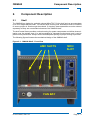
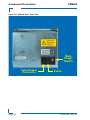
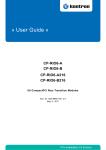
1
» User Guide «
OM6040
MicroTCA™ Four-Slot
Single-Width, Full-Size
Single-Tier
Cube Shelf
Doc. ID:1027-6427, Rev. 2.0
December 10, 2010
If it’s embedded, it’s Kontron.
Preface
OM6040
Revision History
Publication Title: OM6040: MicroTCA™ Four-Slot, Single-Width, Single-Tier Cube Shelf
User Guide
Doc. ID: 1027-6427
Rev.
Brief Description of Changes
Date of Issue
1.0
Initial issue
19-Jan-2009
2.0
Updated to reflect extensive system modifications
10-Dec-2010
Imprint
Kontron Modular Computers GmbH may be contacted via the following:
MAILING ADDRESS
TELEPHONE AND E-MAIL
Kontron Modular Computers GmbH
+49 (0) 800-SALESKONTRON
Sudetenstraße 7
[email protected]
D - 87600 Kaufbeuren Germany
For information about other
Kontron products, please
visit our Internet web site:
www.kontron.com
Disclaimer
Copyright © 2009-2010 Kontron AG. All rights reserved. All data is for information purposes
only and not guaranteed for legal purposes. Information has been carefully checked and is believed to be accurate; however, no responsibility is assumed for inaccuracies. Kontron and the
Kontron logo and all other trademarks or registered trademarks are the property of their respective owners and are recognized. Specifications are subject to change without notice.
Page ii
ID 1027-6427, Rev. 2.0
OM6040
Preface
Table of Contents
Revision History .........................................................................................................ii
Imprint ........................................................................................................................ii
Disclaimer ..................................................................................................................ii
Table of Contents ...................................................................................................... iii
List of Tables ..............................................................................................................v
List of Figures .......................................................................................................... vii
Proprietary Note ........................................................................................................ix
Trademarks ...............................................................................................................ix
Environmental Protection Statement .........................................................................ix
Explanation of Symbols .............................................................................................x
For Your Safety .........................................................................................................xi
Temperature and High Voltage Safety Instructions ..............................................xi
Special Handling and Unpacking Instructions ......................................................xi
General Instructions on Usage ................................................................................ xii
Two Year Warranty .................................................................................................. xiii
1.
Introduction ................................................................................................ 1 - 3
1.1 Overview ................................................................................................. 1 - 3
1.2 Components ............................................................................................ 1 - 3
1.3 Technical Specification ............................................................................ 1 - 5
1.4 Standards ................................................................................................ 1 - 7
1.5 Related Publications ............................................................................... 1 - 8
2.
Component Description ............................................................................ 2 - 3
2.1 Shelf ........................................................................................................ 2 - 3
2.2 Backplane and CM .................................................................................. 2 - 8
2.3 MicroTCA Carrier Hub - MCH ............................................................... 2 - 10
3.
Installation .................................................................................................. 3 - 3
3.1 General ................................................................................................... 3 - 3
3.2 Safety ...................................................................................................... 3 - 4
ID 1027-6427, Rev. 2.0
Page iii
Preface
OM6040
3.3 Prerequisites ............................................................................................3 - 5
3.3.1
Cooling ............................................................................................3 - 5
3.3.2
Filler Panels ....................................................................................3 - 5
3.4 Mounting ..................................................................................................3 - 5
3.5 Adding or Replacing OM6040 Components ............................................3 - 6
3.6 MCH/AMC Module Hot-Swapping ...........................................................3 - 6
3.7 AMC Connector Mating Cycles ................................................................3 - 6
Page iv
ID 1027-6427, Rev. 2.0
OM6040
Preface
List of Tables
1-1
OM6040 Subrack Specifications .............................................................. 1 - 5
1-2
Standards ................................................................................................. 1 - 7
1-3
Related Publications ................................................................................ 1 - 8
3-1
OM6040 Base Solution Configuration ...................................................... 3 - 3
ID 1027-6427, Rev. 2.0
Page v
Preface
OM6040
This page has been intentionally left blank.
Page vi
ID 1027-6427, Rev. 2.0
OM6040
Preface
List of Figures
1-1
OM6040 Shelf - Perspective View ........................................................... 1 - 4
2-1
OM6040 Shelf - Front View ...................................................................... 2 - 3
2-2
OM6040 Shelf - Rear View ...................................................................... 2 - 4
2-3
OM6040 Shelf - Bottom View ................................................................... 2 - 5
2-4
OM6040 Shelf - Top View ........................................................................ 2 - 5
2-5
OM6040 Shelf - Left Side View ................................................................ 2 - 6
2-6
OM6040 Shelf - Right Side View ............................................................. 2 - 6
2-7
OM6040 Shelf - Dimensions .................................................................... 2 - 7
2-8
OM6040 Shelf - Subrack View ................................................................. 2 - 8
2-9
Backplane Topology ................................................................................. 2 - 9
ID 1027-6427, Rev. 2.0
Page vii
Preface
OM6040
This page has been intentionally left blank.
Page viii
ID 1027-6427, Rev. 2.0
OM6040
Preface
Proprietary Note
This document contains information proprietary to Kontron. It may not be copied or transmitted
by any means, disclosed to others, or stored in any retrieval system or media without the prior
written consent of Kontron or one of its authorized agents.
The information contained in this document is, to the best of our knowledge, entirely correct.
However, Kontron cannot accept liability for any inaccuracies or the consequences thereof, or
for any liability arising from the use or application of any circuit, product, or example shown in
this document.
Kontron reserves the right to change, modify, or improve this document or the product
described herein, as seen fit by Kontron without further notice.
Trademarks
This document may include names, company logos and trademarks, which are registered
trademarks and, therefore, proprietary to their respective owners.
Environmental Protection Statement
This product has been manufactured to satisfy environmental protection requirements where
possible. Many of the components used (structural parts, printed circuit boards, connectors,
batteries, etc.) are capable of being recycled.
Final disposition of this product after its service life must be accomplished in accordance with
applicable country, state, or local laws or regulations.
ID 1027-6427, Rev. 2.0
Page ix
Preface
OM6040
Explanation of Symbols
Caution, Electric Shock!
This symbol and title warn of hazards due to electrical shocks (> 60V)
when touching products or parts of them. Failure to observe the precautions indicated and/or prescribed by the law may endanger your
life/health and/or result in damage to your material.
Please refer also to the section “High Voltage Safety Instructions” on
the following page.
Warning, ESD Sensitive Device!
This symbol and title inform that electronic boards and their components are sensitive to static electricity. Therefore, care must be taken
during all handling operations and inspections of this product, in
order to ensure product integrity at all times.
Please read also the section “Special Handling and Unpacking
Instructions” on the following page.
Warning!
This symbol and title emphasize points which, if not fully understood
and taken into consideration by the reader, may endanger your health
and/or result in damage to your material.
Note ...
This symbol and title emphasize aspects the reader should read
through carefully for his or her own advantage.
Page x
ID 1027-6427, Rev. 2.0
OM6040
Preface
For Your Safety
Your new Kontron product was developed and tested carefully to provide all features necessary to ensure its compliance with electrical safety requirements. It was also designed for a
long fault-free life. However, the life expectancy of your product can be drastically reduced by
improper treatment during unpacking and installation. Therefore, in the interest of your own
safety and of the correct operation of your new Kontron product, you are requested to conform
with the following guidelines.
Temperature and High Voltage Safety Instructions
Warning!
All operations on this device must be carried out by sufficiently skilled
personnel only.
Be careful, this device will heat up during operation, and if touched
may cause burns. The temperature of the product housing may reach
up to approximately 50° C. Allow for sufficient cool down before handling after power is turned off.
Caution, Electric Shock!
Before installing your new Kontron product into a system always
ensure that your mains power is switched off. This applies also to the
installation of piggybacks.
Serious electrical shock hazards can exist during all installation,
repair and maintenance operations with this product. Therefore,
always unplug the power cable and any other cables which provide
external voltages before performing work.
Special Handling and Unpacking Instructions
ESD Sensitive Device!
Electronic boards and their components are sensitive to static electricity. Therefore, care must be taken during all handling operations
and inspections of this product, in order to ensure product integrity at
all times.
Do not handle this product out of its protective enclosure while it is not used for operational purposes unless it is otherwise protected.
Whenever possible, unpack or pack this product only at EOS/ESD safe work stations. Where
a safe work station is not guaranteed, it is important for the user to be electrically discharged
before touching the product with his/her hands or tools. This is most easily done by touching a
metal part of your system housing.
It is particularly important to observe standard anti-static precautions when changing piggybacks, ROM devices, jumper settings etc. If the product contains batteries for RTC or memory
backup, ensure that the board is not placed on conductive surfaces, including anti-static plastics or sponges. They can cause short circuits and damage the batteries or conductive circuits
on the board.
ID 1027-6427, Rev. 2.0
Page xi
Preface
OM6040
General Instructions on Usage
In order to maintain Kontron’s product warranty, this product must not be altered or modified in
any way. Changes or modifications to the device, which are not explicitly approved by Kontron
and described in this manual or received from Kontron’s Technical Support as a special handling instruction, will void your warranty.
This device should only be installed in or connected to systems that fulfill all necessary technical and specific environmental requirements. This applies also to the operational temperature
range of the specific board version, which must not be exceeded. If batteries are present, their
temperature restrictions must be taken into account.
In performing all necessary installation and application operations, please follow only the instructions supplied by the present manual.
Keep all the original packaging material for future storage or warranty shipments. If it is necessary to store or ship the board, please re-pack it as nearly as possible in the manner in which
it was delivered.
Special care is necessary when handling or unpacking the product. Please consult the special
handling and unpacking instruction on the previous page of this manual.
Page xii
ID 1027-6427, Rev. 2.0
OM6040
Preface
Two Year Warranty
Kontron grants the original purchaser of Kontron’s products a TWO YEAR LIMITED HARDWARE
WARRANTY as described in the following. However, no other warranties that may be granted or
implied by anyone on behalf of Kontron are valid unless the consumer has the express written
consent of Kontron.
Kontron warrants their own products, excluding software, to be free from manufacturing and
material defects for a period of 24 consecutive months from the date of purchase. This warranty
is not transferable nor extendible to cover any other users or long-term storage of the product.
It does not cover products which have been modified, altered or repaired by any other party
than Kontron or their authorized agents. Furthermore, any product which has been, or is
suspected of being damaged as a result of negligence, improper use, incorrect handling,
servicing or maintenance, or which has been damaged as a result of excessive current/voltage
or temperature, or which has had its serial number(s), any other markings or parts thereof
altered, defaced or removed will also be excluded from this warranty.
If the customer’s eligibility for warranty has not been voided, in the event of any claim, he may
return the product at the earliest possible convenience to the original place of purchase,
together with a copy of the original document of purchase, a full description of the application
the product is used on and a description of the defect. Pack the product in such a way as to
ensure safe transportation (see our safety instructions).
Kontron provides for repair or replacement of any part, assembly or sub-assembly at their own
discretion, or to refund the original cost of purchase, if appropriate. In the event of repair,
refunding or replacement of any part, the ownership of the removed or replaced parts reverts
to Kontron, and the remaining part of the original guarantee, or any new guarantee to cover the
repaired or replaced items, will be transferred to cover the new or repaired items. Any
extensions to the original guarantee are considered gestures of goodwill, and will be defined in
the “Repair Report” issued by Kontron with the repaired or replaced item.
Kontron will not accept liability for any further claims resulting directly or indirectly from any
warranty claim, other than the above specified repair, replacement or refunding. In particular,
all claims for damage to any system or process in which the product was employed, or any loss
incurred as a result of the product not functioning at any given time, are excluded. The extent
of Kontron liability to the customer shall not exceed the original purchase price of the item for
which the claim exists.
Kontron issues no warranty or representation, either explicit or implicit, with respect to its
products’ reliability, fitness, quality, marketability or ability to fulfil any particular application or
purpose. As a result, the products are sold “as is,” and the responsibility to ensure their
suitability for any given task remains that of the purchaser. In no event will Kontron be liable for
direct, indirect or consequential damages resulting from the use of our hardware or software
products, or documentation, even if Kontron were advised of the possibility of such claims prior
to the purchase of the product or during any period since the date of its purchase.
Please remember that no Kontron employee, dealer or agent is authorized to make any modification or addition to the above specified terms, either verbally or in any other form, written or
electronically transmitted, without the company’s consent.
ID 1027-6427, Rev. 2.0
Page xiii
Preface
OM6040
This page has been intentionally left blank.
Page xiv
ID 1027-6427, Rev. 2.0
OM6040
Introduction
Chapter
1
Introduction
ID 1027-6427, Rev. 2.0
Page 1 - 1
Introduction
OM6040
This page has been intentionally left blank.
Page 1 - 2
ID 1027-6427, Rev. 2.0
OM6040
1.
Introduction
1.1
Overview
Introduction
The OM6040 is a cost-optimized, compact and modular MicroTCA™ platform designed for the
implementation of high-performance MicroTCA™ solutions for industrial automation, energy
and medical applications.
The OM6040 single-tier MicroTCA™ Cube shelf consists of a MicroTCA™ backplane, an AC
power supply unit, two cooling fans, a Kontron Single Full-size MicroTCA™ Carrier Hub (MCH),
and four slots for accommodating up to four Single Full-size AMC modules with various configurations of AMC CPUs and peripheral devices. The components are enclosed in a chassis with
a wall-mount panel and two fixed feet allowing the OM6040 to either stand alone on any flat
surface in development environments or be fix mounted using the wall-mount panel. The
OM6040 is closed with the exception of the front slots and cooling air inlets on the bottom and
outlets on the top of the chassis.
The OM6040 is equipped with one large fan that provides forced-air cooling for the front slots
of the system, and a second, smaller fan that provides forced-air cooling for the power supply
and backplane in the rear area of the chassis.
The OM6040’s outstanding features are:
•
•
•
•
MicroTCA™ Cube design
Support for up to four Single Full-size AMCs
Full-size MCH with up to three tongues
Integrated, high-power, low-cost AC power supply unit (instead of high-cost power modules)
• Two integrated cooling fans
• MicroTCA™ backplane:
• Four Single, Full-size AMC module slots
• One three-tongue, Full-size MCH slot
• Fabric support: Gigabit Ethernet, PCI Express, Serial Rapid I/O, SATA/SAS
• Integrated generation of 3.3 VDC management power
• Payload power switching on mezzanine compatiblilty module
• Storage for FRU data
1.2
Components
The OM6040 shelf is comprised of the following elements:
•
•
•
•
•
•
Chassis
Backplane with CM integrated
Subrack
Power Supply Unit (PSU)
Fans
MCH (Kontron AM490n)
ID 1027-6427, Rev. 2.0
Page 1 - 3
Introduction
OM6040
The following figure illustrates the OM6040 shelf configured with the AM4901 MCH. The chassis is provided with a wall-mount panel on the left side of the chassis. The cooling fans are located at the bottom of the chassis and the power supply at the rear. These units are not userserviceable.
Figure 1-1: OM6040 Shelf - Perspective View
Mounting Holes
AMC 1
SLOT
Page 1 - 4
AMC 2
SLOT
MCH
AMC 3
SLOT
AMC 4
SLOT
ID 1027-6427, Rev. 2.0
OM6040
1.3
Introduction
Technical Specification
Table 1-1:
OM6040 Subrack Specifications
FEATURES
Shelf
SPECIFICATIONS
MicroTCA™ cube form designed for Single Full-size AMC Modules
•
Dimensions: 250mm x 157mm x 150mm (depth x width x height)
(with mounting panel)
•
Slot geometry (from left side of the subrack):
slot 1: allocated for Single Full- or Mid-size AMC module
to
slot 4: allocated for Single Full- or Mid-size AMC module
slot 5: allocated for MicroTCA™ Single Full-size Carrier Hub - MCH
•
Two fans: one located at bottom-front area of the shelf, and one in bottom of the
rear bay
•
Rear bay area occupied by the power supply unit, CM, and small fan
Temperature Ranges:
• Operating: 0°C to +55°C
• Storage: -40°C to +70°C
Humidity: 93% RH at 40°C, non-condensing
Weight: 2.8 kg shelf with fans and power supply unit
3.1 kg as above, plus MCH
Backplane and
Compatibility Module
MicroTCA™ compliant, single-tier backplane with:
• Four AMC module connectors
• One three tongue MCH connector
• DC/DC converters for 3.3 VDC management power
• PCIe clock routing to all AMC slots
• Two connectors for interfacing to the MCH Compatibility Module (CM)
Input power distribution and control functionality
Fan power distribution
Backplane FRU data EEPROM
Fabrics:
• Single-star Gigabit Ethernet Fabric (port 0 to each AMC slot; port 1 to AMC slots
1 and 3)
• Fat pipes are routed in a star configuration between AMC ports 4-7 to the MCH.
Depending on the MCH configuration (PCIe switch or SRIO switch) the fat pipes
may be used for 4x lanes of PCIe or 4x lanes of SRIO.
• Fat pipes routing: AMC ports 8-11: AMC slots 1-2 and 3-4
• SATA/SAS porting (AMC Ports 2 and 3):
•
•
•
AMC#1 port 2 to AMC#2 port 2
AMC#1 port 3 to AMC#3 port 2
AMC#3 port 3 to AMC#4 port 2
IPMB-L and I²C interfacing supported for IPMI and local monitor and control
ID 1027-6427, Rev. 2.0
Page 1 - 5
Introduction
Table 1-1:
OM6040
OM6040 Subrack Specifications (Continued)
FEATURES
SPECIFICATIONS
Fans
Two auto restart, brushless DC motors, axial fans:
• Input voltage range: 10 to 14 VDC, nominal 12 VDC
• Maximum air flow: 170 m³/h and 13.5 m³/h
• Power consumption: 5.3 and 1.6 watts
Power Supply Unit
Built-in single AC power supply unit:
• Input voltage range: 85 to 264 VAC; 47 to 63 Hz
• Output voltage: +12 VDC
• Output power: maximum continuous: 250 watts (forced air cooling required)
• Maximum current rating: 20 A
• Power derating: 2.5% per degree from 50°C to 70°C ambient temperature
Page 1 - 6
ID 1027-6427, Rev. 2.0
OM6040
1.4
Introduction
Standards
This Kontron MicroTCA™ Subrack complies with the requirements of the following standards.
Table 1-2:
Standards
COMPLIANCE
CE
TYPE
STANDARD
TEST LEVEL
Emission
EN55022
EN61000-6-3
--
Immission
EN55024
EN61000-6-2
--
Electrical Safety
EN60950-1
--
Mechanical
Mechanical Dimensions IEEE 1101.10
--
Environmental and
Health Aspects
Climatic Humidity
IEC60068-2-78
93% RH at 40°C, non-condensing
WEEE
Directive 2002/96/EC
Waste electrical and electronic equipment
RoHS
Directive 2002/95/EC
Restriction of the use of certain
hazardous substances in electrical and
electronic equipment
Note ...
Kontron performs comprehensive environmental testing of its products in accordance with applicable standards.
Customers desiring to perform further environmental testing of Kontron products must contact Kontron for assistance prior to performing any such testing.
This is necessary, as it is possible that environmental testing can be destructive
when not performed in accordance with the applicable specifications.
In particular, for example, boards without conformal coating must not be
exposed to a change of temperature exceeding 1K/minute, averaged over a
period of not more than five minutes. Otherwise, condensation may cause irreversible damage, especially when the board is powered up again.
Kontron does not accept any responsibility for damage to products resulting
from destructive environmental testing.
ID 1027-6427, Rev. 2.0
Page 1 - 7
Introduction
1.5
OM6040
Related Publications
The following publications contain information relating to this product.
Table 1-3:
Related Publications
PRODUCT
MicroTCA
AMC
PUBLICATION
PICMG® MTCA.0 Micro Telecommunications Computing Architecture R1.0, July 6,
2006
PICMG® AMC.0, Advanced Mezzanine Card Specification R2.0, Nov. 15, 2006
PICMG® AMC.1, PCI Express R2.0, Oct. 8, 2008
PICMG® AMC.2, Gigabit Ethernet R1.0
PICMG® AMC.3, Storage Interfaces R1.0, Aug. 25, 2005
PICMG® AMC.4, Serial Rapid IO R1.0, July 11, 2009
IPMI
IPMI - Intelligent Platform Management Interface Specification, v1.5
IPMI - Platform Management FRU Information Storage Definition, V1.0 Document
Revision 1.1, September 27, 1999
PCI Express
PCI Express Base Specification Revision 1.0a
Rapid IO
Rapid IO Specification Revision 1.3
Serial ATA
Serial ATA 2.5 Specification
All Kontron products
Product Safety and Implementation Guide, ID 1021-9142
Page 1 - 8
ID 1027-6427, Rev. 2.0
OM6040
Component Description
Chapter
21
Component Description
ID 1027-6427, Rev. 2.0
Page 2 - 1
Component Description
OM6040
This page has been intentionally left blank.
Page 2 - 2
ID 1027-6427, Rev. 2.0
OM6040
Component Description
2.
Component Description
2.1
Shelf
The OM6040 is a single-tier, vertically oriented MicroTCA™ Cube shelf and can accommodate
up to four Single Mid-size AMC. For unused slots, dummy filler assemblies must be installed
to ensure proper air flow through the subrack. If required, these assemblies must be ordered
separately as they are not standard elements of the OM6040 shelf.
The shelf’s steel frame provides a robust housing for system components and airflow channelization over the system slots. It is wall-mountable for industrial environments, and it can be
placed on any flat surface. Always ensure that adequate spacing for proper cooling is provided.
The following figures illustrate the mechanical design of the OM6040 shelf.
Figure 2-1: OM6040 Shelf - Front View
AMC SLOTS
MCH
SLOT
FAN BAY
ID 1027-6427, Rev. 2.0
Page 2 - 3
Component Description
OM6040
Figure 2-2: OM6040 Shelf - Rear View
Main
Power
Switch
Input Power
Connector
Page 2 - 4
Fuses
ID 1027-6427, Rev. 2.0
OM6040
Component Description
Figure 2-3: OM6040 Shelf - Bottom View
F
R
O
N
T
Figure 2-4: OM6040 Shelf - Top View
F
R
O
N
T
ID 1027-6427, Rev. 2.0
Page 2 - 5
Component Description
OM6040
Figure 2-5: OM6040 Shelf - Left Side View
MOUNTING HOLES
F
R
O
N
T
MOUNTING HOLES
Figure 2-6: OM6040 Shelf - Right Side View
F
R
O
N
T
Page 2 - 6
ID 1027-6427, Rev. 2.0
OM6040
Component Description
Figure 2-7: OM6040 Shelf - Dimensions
250.00
146.25
150.00
140.00
R1
.75
R4.00
11.25
30.00
220.00
5.00
120.00
157.00
ID 1027-6427, Rev. 2.0
Page 2 - 7
Component Description
2.2
OM6040
Backplane and CM
The OM6040 backplane and CM (MCH Compatibility Module) provide the following basic
functions:
• Fabric interconnectivity for:
• Gigabit Ethernet
• SATA/SAS
• PCIe or SRIO (depends on MCH used)
• Input power distribution and control for payload and management power
• Point-to-point connectivity: slot 1-2 and slot 3-4: ports 8-11
• PCIe clock distribution
• IPMI monitor and control interfacing (IPMB-L)
• Backplane FRU data storage (EEPROM)
• MCH IPMB-0 monitor and control interfacing
• Interfacing for MCH module
The following figures illustrate the basic layout of the backplane and power supply. In addition,
a block diagram of the backplane and the backplane topology are provided.
Figure 2-8: OM6040 Shelf - Subrack View
Page 2 - 8
ID 1027-6427, Rev. 2.0
OM6040
Component Description
Figure 2-9: Backplane Topology
MCH Fabric [A]
to AMC Port 0
MCH Fabric [A]
to AMC Port 1
AMC Port 2
(SATA/SAS)
AMC Port 3
(SATA/SAS)
4
4
/
4
/
4
4
/
4
/
Fat Pipes
MCH Ports [D:G]
to AMC Ports [4:7]
/
AMC Ports
[8:11]
/
Clocks
MCH CLK1
to AMC TCLKA
Clocks
MCH CLK3
to AMC TCLKA
Clocks
(terminated)
AMC TCLKB
to MCH CLK2
12 V
DC-DC
Converter
3.3 V
PRESENT#
ENABLE#
AMC1
AMC2
AMC3
ID 1027-6427, Rev. 2.0
AMC4
MCH
Backplane
Power Management
Page 2 - 9
Component Description
OM6040
The topology of the OM6040 backplane permits a wide range of module configurations. There
are, however, some restrictions as to the use of particular module combinations.
If, for example, CPU modules are installed in both slots 1 and 2 (or 3 and 4), there must be no
SATA functionality active on AMC ports 2 and 3. If both CPUs have SATA active on these ports,
neither of the CPUs will not properly boot.
If PCIe functionality is implemented, by default, slot 1 is configured as the root complex. This
can be changed by setting appropriate PCIe configuration parameters in the MCH.
2.3
MicroTCA Carrier Hub - MCH
The OM6040 is supplied with an appropriate MCH installed at the factory. There are three possible configrations which must be specified at the time the OM6040 is ordered.
There is a base MCH which supports only GbE Fabric, the second version supports GbE and
PCIe, and the third version provides GbE and SRIO.
Page 2 - 10
ID 1027-6427, Rev. 2.0
OM6040
Installation
Chapter
31
Installation
ID 1027-6427, Rev. 2.0
Page 3 - 1
Installation
OM6040
This page has been intentionally left blank.
Page 3 - 2
ID 1027-6427, Rev. 2.0
OM6040
Installation
3.
Installation
3.1
General
The OM6040 shelf itself is an application support platform for MicroTCA™ solutions. In order
to satisfy solution requirements it must be configured accordingly. To assist application developers and system implementers in achieving their goals, the OM6040 is provided with a minimum configuration. Specifically, it is delivered with an appropriate MCH module.
The following table and figures illustrate the base solution configuration of the OM6040. This
configuration is the basis for the information and procedures provided in the following Installation sections.
Table 3-1: OM6040 Base Solution Configuration
COMPONENT
QTY
SYSTEM LOCATION - DESCRIPTION
Subrack
1
Mechanical chassis of OM6040
Backplane
1
-
Power Supply Unit (PSU)
1
Built-in to the rear bay area
Fan
2
One fan in the bottom-front bay area, and one fan in the rear bay area
Filler Panels
0
Must be ordered separately as required. Available are 2HP filler panels and
Full-size dummies
MCH
1
FSA-5: Single Full-size with extraction handle
Required configuration must be specified at time OM6040 is ordered
Legend for Table 3-1:
FSA = front slot area, as seen from front - numbered left to right
QTY = quantity
ID 1027-6427, Rev. 2.0
Page 3 - 3
Installation
3.2
OM6040
Safety
The following precautions must be observed.
Caution, Electric Shock Hazard!
The OM6040 requires AC mains power in the range from 90 to 240 volts for
operation. Therefore, due caution must be exercised when handling or performing operations on the OM6040 when power is applied.
Failure to comply with the above could endanger your life or health and may
cause damage to the OM6040 or other system components including process-side signal conditioning equipment.
ESD Equipment!
The OM6040 contains electrostatic sensitive devices. Ensure that the following precautions are observed to avoid damaging the OM6040:
Discharge clothing before touching the assembly. Tools must also be discharged before use.
Do not touch any board components, connector pins, or board conductive circuits.
If working at an anti-static workbench with professional discharging equipment, ensure compliance with its usage when handling this product.
Page 3 - 4
ID 1027-6427, Rev. 2.0
OM6040
Installation
3.3
Prerequisites
3.3.1
Cooling
The OM6040 requires forced-air cooling which is provided by the cooling fans located on the
bottom side of the subrack in the front and rear bay areas. Adequate ambient airflow to the fan
inlet areas must be ensured. In addition, the area above the subrack must also provide for adequate outlet airflow. Direct re-cycling of outlet air to the inlet area must be avoided to preclude
overheating of the system.
Warning!
Failure to comply with the above can result in improper operation or damage
to the OM6040 or other components installed in the OM6040.
Kontron rejects any and all liability for damage resulting from inadequate
cooling of the OM6040 or components installed in the OM6040.
Warning!
If the OM6040 is operated at temperatures above 45°C, ensure that an inlet
area and an outlet area of 1U (44.45 mm) are provided.
Failure to comply with the above may cause improper operation of or damage
to the OM6040.
3.3.2
Filler Panels
Filler panels for the OM6040 are available as required. Depending on solution requirements
these components may be removed or reconfigured as necessary.
3.4
Mounting
The OM6040 is supplied with a fixed mounting panel for installation in a system cabinet. This
will require mounting hardware which is not supplied with the OM6040.
For operation of the OM6040 on a flat surface, desktop or rack shelf, there are no special
mounting fixtures. In this case, for operation ensure adequate airflow to the OM6040. Care
must also be taken to ensure that the OM6040 cannot fall off of the flat surface.
ID 1027-6427, Rev. 2.0
Page 3 - 5
Installation
3.5
OM6040
Adding or Replacing OM6040 Components
Solution requirements determine the operational configuration of the OM6040. Therefore, it
may or will be necessary to add, remove, or reconfigure components.
Warning!
Remove power from the system before performing any reconfiguration of
these components.
Failure to comply with the above could endanger your life or health and may
cause damage to the OM6040 or other system components including process-side signal conditioning equipment.
Kontron rejects any and all liability for damage resulting from failure to
remove power before performing the above.
AMC modules are normally supplied with documentation which provides instructions or guidelines on their installation or replacement. Please refer to their respective documentation for further assistance. For replacement of the MCH, refer to the MCH User Guide.
The power supply, fans and backplane are not user replaceable.
3.6
MCH/AMC Module Hot-Swapping
The OM6040 as such is designed to support hot-swapping under IPMI control. Hot-swapping,
however, is a function of the individual application requirements and the ability of system components (hardware and software) to support these requirements. Therefore, it is the responsibility of the system integrator to ensure the system operability and compliance with hot-swap
requirements prior to application implementation.
More specifically, for example, the MCH used supports hot-swapping of itself. This in return results effectively in a power off and on cycling of the system as a whole. If this is not desired,
then precautions must be taken to ensure proper hot-swapping of system components.
3.7
AMC Connector Mating Cycles
The OM6040 backplane connectors and the AMC module card-edge connectors are designed
to support at least 200 insertion/extraction cycles. As systems used in a laboratory or development environment may exceed this number of mating cycles over the product life time, the
card-edge connector of each AMC module should be inspected for wear or damage before insertion or after extraction. If a card-edge connector exhibits excessive wear or damage, the
AMC module must be replaced to preclude improper operation of the system.
Page 3 - 6
ID 1027-6427, Rev. 2.0