1
TP20 user's guide
http://www.renishaw.com
TP20 user's guide
Document part number H-1000-5008-04-A
Issued 11 2014
1
TP20 user's guide
http://www.renishaw.com
General information
© 1998 2014 Renishaw plc. All rights reserved.
This document may not be copied or reproduced in whole or in part, or transferred to any other media or language, by any means, without
the prior written permission of Renishaw.
The publication of material within this document does not imply freedom from the patent rights of Renishaw plc.
Disclaimer
RENISHAW HAS MADE CONSIDERABLE EFFORTS TO ENSURE THE CONTENT OF THIS DOCUMENT IS CORRECT AT THE DATE
OF PUBLICATION BUT MAKES NO WARRANTIES OR REPRESENTATIONS REGARDING THE CONTENT. RENISHAW EXCLUDES
LIABILITY, HOWSOEVER ARISING, FOR ANY INACCURACIES IN THIS DOCUMENT.
Trademarks
RENISHAW® and the probe emblem used in the RENISHAW logo are registered trademarks of Renishaw plc in the UK and other
countries.
apply innovation is a trademark of Renishaw plc.
All brand names and product names used in this document are trade names, service marks, trademarks, or registered trademarks of their
respective owners.
Windows XP, Windows 2000, Vista and Windows 7 are registered trade names of the Microsoft Corporation.
All trademarks and trade names are acknowledged.
WEEE
The use of this symbol on Renishaw products and/or accompanying documentation indicates that the product should not be mixed with the
general household waste upon disposal. It is the responsibility of the end user to dispose of this product at a designated collection point for
waste electrical and electronic equipment (WEEE) to enable reuse or recycling. Correct disposal of this product will help save valuable
resources and prevent potential negative effects on the environment. For more information, please contact your local waste disposal service
or Renishaw distributor.
Warranty
Renishaw plc warrants its equipment for a limited period (as set out in our Standard Terms and Conditions of Sale) provided that it is
installed exactly as defined in associated Renishaw documentation.
Prior consent must be obtained from Renishaw if non-Renishaw equipment (e.g. interfaces and/or cabling) is to be used or substituted.
Failure to comply with this will invalidate the Renishaw warranty.
Claims under warranty must be made from authorised service centres only, which may be advised by the supplier or distributor.
Issued 11 2014
2
TP20 user's guide
http://www.renishaw.com
Care of equipment
Renishaw probes and associated systems are precision tools used for obtaining precise measurements and must therefore be treated with
care.
Changes to Renishaw products
Renishaw reserves the right to improve, change or modify its hardware or software without incurring any obligations to make changes to
Renishaw equipment previously sold.
Patents
Features of Renishaw's TP20 product, and other associated and similar Renishaw products, are the subject of one or more of the following
patents and / or patent applications:
US6012230
Issued 11 2014
3
TP20 user's guide
http://www.renishaw.com
Warnings
The use of eye protection is recommended. Pinch hazards exist between parts and between moving and static parts. Beware of
unexpected movement. You should remain outside the full working envelope of probe head/extension bar/probe combinations.
It is the machine supplier's responsibility to ensure that the user is made aware of any hazards involved in operation, including those
mentioned in renishaw product documentation, and to ensure that adequate guards and safety interlocks are provided.
Under certain circumstances, the probe signal may falsely indicate a probe seated condition. Do not rely on probe signals to stop the
machine.
Limitations of use
CAUTION: One option of the TP20 probe system uses a magnetically-actuated inhibit system. It is important to apply the following
limitations when using the inhibit version TP20. Neglecting to do so may result in failure of the probe to trigger.
1. The inhibit TP20 may not be armed at a distance of up to 100 mm from the front of the MCR20 probe module change rack.
2. Do not use the inhibit TP20 to gauge magnetised parts or parts held in magnetic fixtures.
3. Do not use the Renishaw PE series extension bars with the inhibit TP20 unless they have been fully de-magnetised. In all these instances
the use of the non-inhibit TP20 probe body will ensure that the probe system operates fully.
CAUTION: The TP20 non-inhibit probe can only be used for automatic stylus changing using the MCR20 probe module change rack
when the probe inhibit is controlled by the CMM. In the case of any uncertainty, do not attempt to perform automatic stylus changing
with a TP20 non-inhibit probe and an MCR20 until the CMM supplier has checked the CMM for compliance to this requirement.
Issued 11 2014
4
TP20 user's guide
http://www.renishaw.com
Introduction
This installation and user's guide supports the following Renishaw products:
The TP20 touch-trigger probe system which includes the probe body and probe module (inhibit and non-inhibit versions)
The MCR20 probe module change rack (automatic operation)
The TCR20 probe module change rack (automatic operation)
The MSR1 module storage rack (manual operation)
The Renishaw TP20 touch-trigger probe is a 5-way or 6-way kinematic probe with the facility to change stylus configurations without the
need for re-qualification. A direct replacement for the industry-proven Renishaw TP2, the TP20 can be easily retrofitted into existing TP2
applications to bring this additional facility to both manual and DCC co-ordinate measuring machines (CMMs).
The TP20 comprises a twopiece design – a probe body (with or without magnetic actuation device) and detachable probe modules. TP20
probe modules can be stored in the MSR1 for manually exchanging the probe modules, or in the MCR20 where automatic changing of the
probe module(s) is possible under measurement program control. The TCR20 rack should be used for TP20 probe module changing with
a PH20 system.
Forming part of Renishaw's comprehensive CMM touch-trigger probe range, the TP20 is fully compatible with all Renishaw M8 probe
heads, including those fitted with the Renishaw autojoint incorporating Renishaw's PAA range of adaptors and extension bars. Wherever
necessary, probe reach may be increased in M8 applications by use of the Renishaw PEL range of extension bars.
Further information on these products may be obtained from Renishaw's website.
Issued 11 2014
5
TP20 user's guide
http://www.renishaw.com
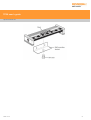
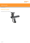
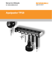
TP20 touch-trigger probe kit
The standard Renishaw TP20 touch-trigger probe kit (see following figure) comprises the following primary components:
One TP20 probe body
One or two TP20 probe modules (see TP20 probe kits for available combinations)
Probe and stylus tools
TP20 probe body
The probe body incorporates a standard Renishaw M8 × 1.25 mm screw connector mount and is designed to house the mating half of the
probe module's kinematic coupling.
TP20 inhibit probe body
This contains the magnetic proximity switch necessary to inhibit triggering of the probe during automatic changing of the probe modules.
TP20 non-inhibit probe body
This probe body does not include the magnetic proximity switch and so can be used for any application, including those where strong
magnetic fields are present.
Issued 11 2014
6
TP20 user's guide
http://www.renishaw.com
Issued 11 2014
7
TP20 user's guide
http://www.renishaw.com
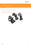
TP20 probe modules
Each probe module, which houses the kinematic switching touch sensor mechanism, carries the stylus assembly and provides overtravel in
the X, Y and +Z axes (–Z is offered when using the TP20 6way probe module). Incorporating an M2 stylus mounting, each probe module is
compatible with Renishaw's comprehensive range of M2 styli.
Designed to minimise the possibility of probe module misalignment generating a probe ‘seated' signal, the probe module is held in position
by a magnetically retained, highly repeatable kinematic coupling.
Electrical contact pins conduct the probe sense voltage through the coupling.
Trigger force options
The standard force probe module is suitable for most applications (when used with the recommended stylus range), but sometimes the
effects of stylus length and mass, combined with machine acceleration and vibration, can cause the probe to false trigger (these are
referred to as ‘spurious triggers').
To allow the TP20 to be used on co-ordinate measuring machines where acceleration forces or vibration would otherwise result in spurious
triggers, a choice of higher force probe modules is available. A low force probe module is also available for measurement of delicate
materials. Refer to the applications guide later in this document for information on how to select the correct probe module for your
application.
The type of probe modules supplied with your probe will be clearly marked on each probe module's front ring. The probe modules also carry
a colour-coded front cap as follows:
Low force (LF) probe module (green cap)
Standard force (SF) probe module (black cap)
Medium force (MF) probe module (grey cap)
Extended force (EF) probe module (brown cap)
6-way (6W) probe module (blue cap)
Extension module 1 standard force (EM1 STD) (black cap)
Extension module 2 standard force (EM2 STD) (black cap)
Issued 11 2014
8
TP20 user's guide
http://www.renishaw.com
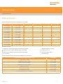
TP20 probe kits
The following TP20 probe kits are available from your supplier:
Inhibit probe body
Non-inhibit probe body
LF probe module
MF probe module
A-1371-0290
A-1371-0640
A-1371-0291
A-1371-0641
1
A-1371-0292
A-1371-0642
1
A-1371-0293
A-1371-0643
2
A-1371-0294
A-1371-0644
1
A-1371-0295
A-1371-0645
A-1371-0428
A-1371-0603
1
A-1371-0429
A-1371-0604
1
A-1371-0370
A-1371-0656
A-1371-0371
A-1371-0657
A-1371-0372
A-1371-0658
A-1371-0390
A-1371-0602
SF probe module
EF probe module
2
1
1
1
2
1
1
1
1
1
1
All probe kits contain:
Probe body - inhibit or non-inhibit as selected from the table
S9 doubleended ‘C' spanner
Number and type of probe modules as given in the table
S7 stylus tools (× 2)
TP20 system installation and user's guide (H-1000-5008)
CK200 cleaning material
S1 ‘C' spanner
Test certificates
The following TP20 probe module kits are available from your supplier:
Issued 11 2014
TP20 probe module kit (probe module only)
Part number
Low force probe module
A-1371-0392
Standard force probe module
A-1371-0270
Medium force probe module
A-1371-0271
Extended force probe module
A-1371-0272
6-way probe module
A-1371-0419
EM1 STD probe module
A-1371-0430
EM2 STD probe module
A-1371-0431
EM1 STD and EM2 STD probe modules
A-1371-0432
9
TP20 user's guide
http://www.renishaw.com
MCR20 probe module changing rack kit
NOTE: Renishaw supplies eight types of MCR20 probe module changing rack kit, each kit providing a different combination of probe
modules.
The MCR20 probe module changing rack kit comprises the following primary components:
One Renishaw MCR20 probe module changing rack
One Renishaw SCR200 mounting kit
One location piece
One Renishaw PS2R stylus
Two Renishaw TP20 probe modules (probe module combination supplied will depend on part number of kit)
The MCR20 probe module changing rack, which can be easily mounted onto a CMM using the Renishaw SCR200 mounting kit and
location piece, is designed to securely hold stored probe modules for automatic changing, and to protect these stored probe modules from
airborne contaminants that may be present within the working environment. Only seven datum points are needed to set the MCR20 rack
alignment and probe module changing co-ordinates.
When using the rack, the inhibit version of the TP20 probe must be used. By generating a magnetic field about the front of each docking
port lid, the MCR20 effectively ‘closes' the probe's inhibit switch during a probe module changing cycle. Rack function is completely passive
and no electrical input is required.
During automatic changing of probe modules, limited crash protection is provided by hinged overtravel mechanisms incorporated within
both the base and the docking port assembly of the MCR20. Provided any collision occurs in the direction of overtravel, the hinged
overtravel mechanisms can be manually reset and it should not normally be necessary to re-datum the rack.
MCR20 probe module changing rack kits are available with the following combinations of probe modules and may be ordered from your
supplier:
Issued 11 2014
10
TP20 user's guide
http://www.renishaw.com
MCR20 kit part number
LF probe module
SF probe module
A-1371-0261
2
A-1371-0262
1
A-1371-0263
1
MF probe module
1
1
A-1371-0264
2
A-1371-0265
1
A-1371-0266
1
2
A-1371-0267
1
A-1371-0268
1
A-1371-1100
2
Issued 11 2014
EF probe module
1
1
11
TP20 user's guide
http://www.renishaw.com
TCR20 module change rack for PH20
TCR20 is a compact probe module rack for use with PH20 that provides the capability for quick and repeatable tool changing and tip
correction.
Based on the industry standard range of MCR20 rack systems, TCR20 securely stores modules for rapid automatic changing, protecting
mating surfaces from any airborne contaminants within the working envelope of the machine.
TCR20 carries the full range of TP20 modules which are compatible with the PH20 system and can accommodate up to six module / stylus
combinations.
TCR20 features an integrated tip datum artefact in the centre of the rack assembly, minimising the cycle time of the tip correct procedure.
Tip correction is key when the highest level of accuracy is required. It compensates for any residual variations following a tool change,
maintaining a market leading level of accuracy from PH20.
The TCR20 module change rack kit is not supplied with any TP20 probe modules. It can be ordered from your supplier under the following
part number:
Issued 11 2014
Part number
Description
A-1371-1001
TCR20 rack kit
12
TP20 user's guide
http://www.renishaw.com
MSR1 module storage rack kit
The optional MSR1 module storage rack kit is not supplied with any TP20 probe modules. It is available in two different mounting options
(please refer to the installation section for details).
The two different versions can be ordered from your supplier under the following part numbers:
Issued 11 2014
Mounting option
Part number
CMM table mounted
A-1371-0347
Wall mounted
A-1371-0330
13
TP20 user's guide
http://www.renishaw.com
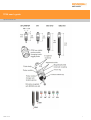
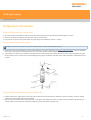
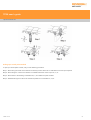
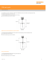
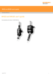
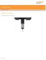
Component connection
Fitting a TP20 probe onto a probe head
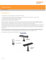
1. By hand, screw the threaded end of the probe body into the M8 bush of the probe head and hand-tighten to secure.
2. Fit the S1 ‘C' spanner (supplied) onto the probe body as shown below.
3. Using the S1 ‘C' spanner, fully handtighten the probe body into the M8 bush (0.3 Nm 0.5 Nm).
Fitting a stylus onto a probe module
NOTE: For advice on both stylus and probe module selection, refer to the applications guide.
1. Ensuring that you have selected the correct probe module for your given application (see probe module selection), screw the threaded
end of your chosen stylus into the M2 stylus mount of the probe module and hand-tighten to secure.
2. Using the type S7 stylus tools provided, or type S20 spanner if fi tting a stylus from the Renishaw GF range, fully hand-tighten the stylus
into the stylus mount to achieve the recommended tightening torque of between 0.05 Nm and 0.15 Nm (maximum permissible torque is
0.3 Nm).
Fitting a probe module and stylus onto a probe body
1. Visually examine the mating faces of both the probe module and the probe head for cleanliness. Where necessary, clean the mating
surfaces using the CK200 cleaning kit (supplied).
2. Offer up the probe module to the probe body and, ensuring the three alignment marks on both the probe module and probe body are
correctly aligned, allow the probe module to engage the probe body under magnetic force.
Issued 11 2014
14
TP20 user's guide
http://www.renishaw.com
Issued 11 2014
15
TP20 user's guide
http://www.renishaw.com
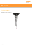
Mounting MCR20 onto the CMM
To mount the MCR20 probe module change rack onto your CMM, carry out the following procedure:
CAUTION: For optimum crash protection, it is recommended that the MCR20 is mounted as close as possible to the extreme edge
of the CMM's operating envelope.
1. Place the location piece in the desired position on the CMM table and secure in place using the M8 / M10 bolt and washer supplied.
Using the appropriate Allen key (supplied), fully hand-tighten the M8 / M10 bolt into the threaded insert within the CMM table
2. Mount the lower base of the MCR20 probe module change rack over the location piece and rotate the X axis of the rack until the required
alignment is obtained.
3. Using the 1.5 mm hexagonal key supplied, fully hand-tighten the M3 cone point grubscrew (0.5 Nm - 1 Nm) to lock the MCR20 in position.
NOTES: Whilst the TP20 system does not require that the MCR20 is aligned with the CMM axes, ease of programming or software
constraints may make alignment with the CMM axes desirable.
The MCR20 is not designed for horizontal operation with the ports in a vertical orientation.
Issued 11 2014
16
TP20 user's guide
http://www.renishaw.com
Datuming MCR20
NOTES: Renishaw recommends that datuming of the MCR20 is performed using the Renishaw PS2R stylus supplied. If a different
stylus is to be used, the length (L) must be either 20 mm or 30 mm and the appropriate ball radius (R) must be used to calculate
offsets.
It is strongly recommended that the EM1 STD and EM2 STD probe extension modules are not used for datuming of the MCR20, as
the extended probe length may lead to increased concentricity errors within the probe system.
The following instructions assume that uncompensated probing points are taken, and therefore that the target positions for port
docking are absolute machine co-ordinates.
Aligning MCR20 to the CMM axes
To align the MCR20 probe module changing rack to the axes of your CMM, carry out the following procedures:
1.
2.
3.
4.
Latch all port lids in their open position by pushing each lid fully open and engaging the locking pegs into the slots in the docking plate.
Take points P1 and P2.
Using the 1.5 mm hexagonal key supplied, fully release the M3 cone point grubscrew within the base of the MCR20.
Adjust the orientation of the MCR20 until the runout between points P1 and P2 is less than 0.25 mm. Retaining the MCR20 in this
position, re-tighten the M3 cone point grubscrew (0.5 Nm - 1 Nm) using the 1.5 mm hexagonal key supplied.
Establishing the docking depth (Y)
To establish the docking depth (Y) of the MCR20 ports, carry out the following procedure:
1. Take points P1 and P2.
2. Establish the docking depth for all ports using the following formula:
{Y value of line P1/P2 + R (1 mm) + 8.75 mm}
where R = stylus ball radius
Establishing the docking height (Z)
To establish the docking height (Z) of the MCR20 ports, carry out the following procedure:
1. Take points P3, P4 and P5. From the three points taken, construct a Z axis plane for the rack.
2. Establish the docking height for all ports using the following formula:
{Z value of plane P3/P4/P5 – L (20 mm) – R (1 mm) – 21.25 mm}
where L = stylus length
Issued 11 2014
17
TP20 user's guide
http://www.renishaw.com
Establishing the docking centre for port 1
To establish the docking centre for port 1 (X1), carry out the following procedure:
NOTE: The stylus shank may be used to take points P6 and P7.
1. Take points P6 and P7.
2. Establish the docking centre for port 1 (X1) using the following formula:
{centre point of P6/P7 = X1}
Issued 11 2014
18
TP20 user's guide
http://www.renishaw.com
Establishing the docking centre for ports 2 to 6
To establish the docking centre for ports 2 (X2) to 6 (X6), perform the following calculations:
Docking centre port 2 (X2) = X1 + 30 mm
Docking centre port 3 (X3) = X2 + 30 mm
Docking centre port 4 (X4) = X3 + 30 mm
Docking centre port 5 (X5) = X4 + 30 mm
Docking centre port 6 (X6) = X5 + 30 mm
Establishing the docking target co-ordinates
CAUTION: The Y values may be different for each port if the MCR20 is not aligned with the CMM axes.
To establish the docking centre co-ordinates of ports 1 (X1) to 6 (X6), perform the following calculations:
Port 1 = X1, Y, Z
Port 2 = X2, Y, Z
Port 3 = X3, Y, Z
Port 4 = X4, Y, Z
Port 5 = X5, Y, Z
Port 6 = X6, Y, Z
Issued 11 2014
19
TP20 user's guide
http://www.renishaw.com
Mounting TCR20 onto the CMM
NOTE: To minimise the machine volume lost it is recommended that the TCR20 is mounted as close as possible to the extreme edge
of the CMM's operating envelope.
1. Fix the rack base to the CMM bed using the appropriate fixing screw. Depending upon the size of screw required it may be necessary to
also use a washer.
2. Fit the TCR20 leg into the base and orientate the rack. Secure the rack in the correct orientation by tightening the three grubscrews that
are located in the rack base.
TCR20 alignment and change routine
The following routines are handled through UCCserver for TCR20:
Alignment routine
Put down and pick up routine
Safe position
Issued 11 2014
20
TP20 user's guide
http://www.renishaw.com
Mounting MSR1 onto the CMM
CAUTION: The MSR1 rack is not crash-protected. It is recommended that the rack is mounted outside or close to the edge of the
working volume of the CMM.
Two mounting options are available for the MSR1 - CMM table mounted and wall mounted.
Mounting MSR1 onto a CMM table
To mount MSR1 onto your CMM table, carry out the following procedure:
1. Place the base over a threaded insert at the desired location on the CMM table and screw down using the M8 or M10 bolt supplied.
2. Screw the leg a few turns into the M10 nut located in the underside of the rack extrusion. Slide the rack along to the centre or other
location, as required, and tighten by hand.
3. Push the lower end of the leg firmly into the base and rotate the rack to the required orientation. Tighten the grubscrews using the
hexagonal key supplied.
Issued 11 2014
21
TP20 user's guide
http://www.renishaw.com
Mounting MSR1 onto a wall
To mount MSR1 onto a wall, carry out the following procedure:
1. Fix the wall mounting bracket (supplied) in the desired location using the holes or other secure means.
2. Locate the rack on the bracket and secure by engaging the M10 bolt (supplied) a few turns into the M10 nut located in the underside of
the rack extrusion. Slide the rack along until it is centralised or otherwise located as required and tighten the bolt.
Issued 11 2014
22
TP20 user's guide
http://www.renishaw.com
Issued 11 2014
23
TP20 user's guide
http://www.renishaw.com
Product operation
Storing and changing probe modules
NOTES: The inhibit switch in the inhibit version of the TP20 body will be automatically actuated by the magnetic field when it
approaches the front of the MCR20 probe module changing rack. The minimum distance from the MCR20 probe module changing
rack at which the TP20 is armed will vary with height.
When using long styli fitted to the EM1 STD or EM2 STD probe modules, do not store them in ports three or four of the MCR20 or
MSR1 rack.
Calculating the safe clearance position
The recommended safe clearance position is located at the minimum distance from the port centre (at docking height Z) where the probe
will be armed, if the probe module is attached.
The safe clearance position for any port (n) can be calculated from:
{Xn, Ys, Z} where Ys = Y – 100 mm
Storing a probe module
To store a probe module, carry out the following procedure:
Step 1.- Move to the safe clearance position Xn, Ys, Z for the vacant port (n).
Step 2.- Move to the docking target co-ordinate for port (n) along the Y-axis at the docking height (Z).
Step 3.- Move up to the release height Zr, where: {Zr = Z + 3 mm}
Step 4.- Withdraw from the release co-ordinate, maintaining the release height, along the Y-axis to a point clear of the port lids where the
probe remains inhibited. This point is known as the ‘retract point' (RP) and has the coordinates: {RP = Xn, Yr, Zr} where Yr = Y – 17.2 mm
Issued 11 2014
24
TP20 user's guide
http://www.renishaw.com
Picking up a stored probe module
To pick up a stored probe module, carry out the following procedure:
Step 1.- Move along the X-axis in the direction necessary to arrive at the RP co-ordinates for the next port required.
Step 2.- Move along the Y-axis to the release co-ordinates above the centre of port Xn, Y, Zr.
Step 3.- Move down to the docking co-ordinates Xn, Y, Z to attach the probe module.
Step 4.- Withdraw along the Y-axis to the clearance position at co-ordinates Xn, Ys, Z.
Issued 11 2014
25
TP20 user's guide
http://www.renishaw.com
Summary of probe module changing procedure
Operation
X axis
Y axis
Z axis
Xn
Ys
Z
Move to docking position
*
Y
*
Release probe module
*
*
Zr
Move to retract point (RP)
*
Yr
*
Xn
*
*
Enter port
*
Y
*
Move to docking position
*
*
Z
Move to safe clearance position
*
Ys
*
Safe clearance position for port (n)
Select next port (n)
Xn = X1 to X6 as selected by the user
Ys = Y – 100 mm
Zr = Z + 3 mm
Yr = Y – 17.2 mm
* = No change to the previous setting of the axis register
Issued 11 2014
26
TP20 user's guide
http://www.renishaw.com
Using the MSR1 module storage rack
The location points for the TP20 probe modules are positioned approximately below the numbered labels on the rack. Accurate positioning
is not necessary, as the magnetic force will pull them into the correct position.
The probe modules are held magnetically in the MSR1 and can be rotated if required.
Issued 11 2014
27
TP20 user's guide
http://www.renishaw.com
Technical data
Measuring performance
NOTE: The following data is derived from high accuracy test rig measurements and may not represent the performance achievable
on a CMM. Please consult your CMM supplier for overall system accuracy information.
Performance at 10mm stylus length
Probe module type
Unidirectional repeatability*
(2σ)
2D (XY) form measurement deviation*
LF
0.35 µm
± 0.6 µm
MF
0.35 µm
± 0.8 µm
SF
0.5 µm
± 1 µm
EF
0.65 µm
± 2 µm
6-way
0.8 µm
± 1.5 µm
EM1 STD
0.35 µm
± 0.8 µm
EM2 STD
0.35 µm
± 0.8 µm
* Measured at a trigger speed of 8 mm/s
Test stylus ball diameter 4 mm
Probing forces and overtravel limits
Probe
module
type and
stylus
length
XY (Trigger Z (Trigger
XY
+Z
-Z
XY
+Z
-Z (Overtravel
force
force
(Overtravel (Overtravel (Overtravel
(Overtravel
(Overtravel displacement)
(nominal at (nominal at force (max. force (max. force (max. displacement) displacement)
stylus tip)) stylus tip)) at stylus tip)) at stylus tip)) at stylus tip))
LF 10 mm
0.055 N
(5.5 gf)
0.65 N
(65 gf)
0.09 N
(9 gf)
1.15 N
(115 gf)
-
±14°
3.1 mm
-
SF 10 mm
0.08 N
(8 gf)
0.75 N
(75 gf)
0.2 N - 0.3 N
(20 gf - 30 gf)
3.5 N
(350 gf)
-
±14°
4 mm
-
MF 25 mm
0.1 N
(10 gf)
1.9 N
(190 gf)
0.2 N - 0.4 N
20 gf - 40 gf)
7N
(700 gf)
-
±14°
3.7 mm
-
EF 50 mm
0.1 N
(10 gf)
3.2 N
(320 gf)
0.2 N - 0.5 N
(20 gf - 50 gf)
10 N
(1kgf)
-
±14°
2.4 mm
-
6-way 10
mm
0.14 N
(14 gf)
1.6 N
(160 gf)
0.25 N
(25 gf)
2.5 N
(250 gf)
9N
(900 gf)
±14°
4.5 mm
1.5 mm
EM1 STD
10 mm
0.08 N
(8 gf)
0.75 N
(75 gf)
0.2 N - 0.3 N
(20 gf - 30 gf)
3.5 N
(350 gf)
-
±14°
4 mm
-
EM2 STD
10 mm
0.08 N
(8 gf)
0.75 N
(75 gf)
0.2 N - 0.3 N
(20 gf - 30 gf)
3.5 N
(350 gf)
-
±14°
4 mm
-
Issued 11 2014
28
TP20 user's guide
http://www.renishaw.com
* NOTE: The probe module may detach if this value is exceeded.
Probe module changing repeatability
Probe module changing method
Repeatability
Automatic changing
±0.5 µm
Manual changing
±1 µm
Technical specifications
TP20
Product compatibility
The TP20 is suitable for use with all Renishaw probe interfaces and probe heads which service
the TP1, TP2 and TP6 touch-trigger probes.
The TP20 is compatible with the PEL, PK, PAA and PEM series of probe extensions /
adaptors.
Diameter
13.2 mm
Length - LF / SF / MF / EF
38 mm
Length - EM1 STD
88 mm
Length - EM2 STD
113 mm
Length - 6-way
42 mm
Probe mount
Thread M8 x 1.25 x 5 mm
Stylus mount
Thread M2 x 0.4
Sense directions - LF / SF / MF / EF /
EM1 STD / EM2 STD
5way (± X, ± Y, + Z)
Sense directions - 6-way
6way (± X, ± Y, ± Z)
Probe module pull-off force
10 N (1 kgf) maximum
Sealing
IP30
Cable length
50 m with (24 awg) conductors
Probe modules life
25,000 changes
Issued 11 2014
29
TP20 user's guide
http://www.renishaw.com
MCR20
Length
200 mm
Width
60 mm
Height
145 mm
Port entry velocity
Maximum 800 mm/s
Mounting orientation
Not designed for horizontal operation with the ports in a vertical orientation
Y axis overtravel
Hinged breakout from base
55 mm travel at port height
Z axis overtravel
Hinged docking port assembly
90° travel in –Z axis
Inhibit range
100 mm from port centre
TCR20
Width
200 mm (7.87 in)
Depth
57 mm (2.24 in)
Base diameter
50 mm (1.97 in)
Height to top of rack
186 mm (7.32 in)
Height to bottom of ports
159 mm (6.26 in)
Port entry velocity
Maximum 800 mm/s (31.5 in/sec)
Mounting orientation
Ports in a horizontal position only
Tip correct artefact
Centre of rack assembly
Overtravel
Not required - protection provided by PH20 head
Inhibit range
Not required - provided by UCC controller
MSR1
Length
285 mm
Width
86 mm
Height
285 mm
Number of ports
6
Mounting
Wall mounted
CMM table mounted
Issued 11 2014
30
TP20 user's guide
http://www.renishaw.com
Applications guide
Probe module selection
To obtain the best possible performance from your TP20 probe, it is important to select the correct probe module for your specific
application. When choosing the probe module to be used, the following considerations should be addressed:
The mass of the stylus assembly and its centre of gravity - it is always best to use the shortest stylus possible
The orientation of the probe body
The levels of acceleration and vibration to which the TP20 probe will be subjected - these will vary with each type of CMM and movement
velocity
The following probe modules are available for use with the TP20 probe. Each probe module is clearly marked on its front ring and also
carries a colour-coded front cap as follows:
Low force probe module (green cap)
Standard force probe module (black cap)
Medium force probe module (grey cap)
Extended force probe module (brown cap)
6-way probe module (blue cap)
EM1 STD probe module (black cap)
EM2 STD probe module (black cap)
NOTE: It is recommended that a standard force probe module is always used, except where the application or machine acceleration
or vibration would cause the TP20 to false trigger.
Low force probe module
The low force probe module, identified by a green cap, is suited to applications that require a low trigger force, for example rubber seals.
Standard force probe module
The standard force probe modules (SF, EM1 STD and EM2 STD) are identified by black caps and are suited to the majority of
applications.
Medium force probe module
The medium force probe module, identified by a grey cap, is provided for use where a higher trigger force than standard is required.
Extended force probe module
The extended force probe module is identified by a brown cap. Typically, this probe module will only be required with large stylus
assemblies, and where spurious triggers caused by machine vibration and acceleration preclude the use of either the standard or medium
force probe modules.
6-way probe module
The 6-way probe module is identified by a blue cap. This probe module is designed for 6-way operation where there is a requirement to
measure in the –Z direction, for example when measuring undercuts.
Issued 11 2014
31
TP20 user's guide
http://www.renishaw.com
Stylus selection
NOTE: Choosing the best stylus for a given application is an important factor in achieving optimum probe performance. For further
information on the full range of Renishaw styli, please refer to Renishaw's styli and accessories brochure (H 1000-3200) which can be
ordered from your supplier or downloaded from Renishaw's web site, www.renishaw.com.
When selecting a stylus, it is important that the stylus length is kept to the minimum required to access all features to be measured, and that
the stylus type offers the maximum possible stiffness. Factors that affect stiffness are:
Joints in the styli that tend to reduce rigidity and should therefore be kept to the absolute minimum
Stem diameters that are governed by the ball tip diameter of the stylus
Stem material that can be stainless steel, ceramic or graphite fibre (GF)
It is also important to ensure that the stylus ball diameter chosen is as large as is practical. This not only ensures that the stylus will be as stiff
as possible, but also reduces the stylus's susceptibility to surface form and surface finish.
Owing to the modular construction of the TP20, when selecting and using styli the following criteria should be applied:
Work only within the recommended stylus limits for each probe module (refer to Recommended stylus limits)
Always use the shortest possible stylus
If using larger styli than those recommended for use with each probe module, always conduct trials to establish the effect on measuring
performance
Minimise the mass of styli by using either ceramic or graphite fibre (GF) stems
Recommended stylus limits
Owing to the modular construction of the TP20 probe, it is recommended that the limits shown in the figures below are applied when
selecting styli to be used.
Low force probe module
The low force probe module has the following recommended stylus limits:
Steel and carbide styli up to 30 mm long
No star or cranked styli
Standard force probe module
Issued 11 2014
32
TP20 user's guide
http://www.renishaw.com
The standard force probe modules (SF, EM1 STD and EM2 STD) can be used with the following range of styli:
Steel and carbide styli up to 40 mm long
Renishaw graphite fibre (GF) type styli up to 50 mm long
Star and cranked styli up to 20 mm offset
Medium force and extended force probe modules
The medium force and extended force probe modules have the following recommended stylus limits:
Any stylus type up to 60 mm long
Star and cranked styli up to 20 mm offset
6-way probe module
The recommended stylus limits for the 6-way probe module are:
Any stylus type up to 30 mm long
Star and cranked styli up to 10 mm offset
Issued 11 2014
33
TP20 user's guide
http://www.renishaw.com
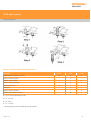
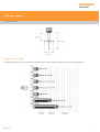
Comparative stylus lengths
A comparison of the minimum and maximum stylus lengths for use with each probe module is shown in the following figure:
Issued 11 2014
34
TP20 user's guide
http://www.renishaw.com
Product maintenance
NOTE: Maintenance of the TP20 probe is restricted to the periodic cleaning of the kinematic couplings of both the probe body and
the probe module(s). To aid cleaning of these couplings, each TP20 probe is supplied with a Renishaw CK200 cleaning kit.
Each Renishaw CK200 cleaning kit contains a specialised material to effectively remove contamination from the precision ball / V groove
seatings, electrical contacts and permanent magnets of the kinematic couplings.
NOTE: When operating the TP20 probe in environments subjected to airborne contamination, the user should determine the
frequency of cleaning required to ensure the kinematic couplings remains uncontaminated.
Whilst the kinematic coupling mechanism is highly tolerant of nonmetallic dust, regular inspection and cleaning with the material provided is
recommended to ensure continued high performance. Instructions for use are included with the cleaning kit. If required, replacement kits
can be ordered from your supplier (Renishaw part number A-1085-0016).
Probe modules that are not attached to the probe body should be stored in the MCR20, TCR20 or MSR1 rack, or in their transport boxes, to
prevent contamination.
Issued 11 2014
35
Renishaw plc
New Mills, Wotton-under-Edge,
Gloucestershire, GL12 8JR
United Kingdom
T +44 (0)1453 524524
F +44 (0)1453 524901
www.renishaw.com/cmmsupport
For worldwide contact details,
please visit our main website at
www.renishaw.com/contact
Issued 11 2014