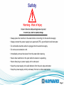
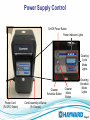
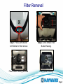
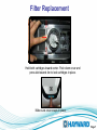
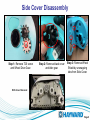
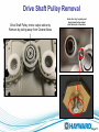
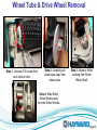
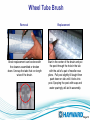
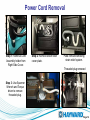
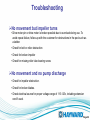
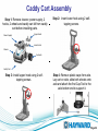
1
AquaVac 500 Troubleshooting Guide ® © 2014 Hayward Industries Inc. Table of Contents Safety Precautions Page 1 Service Tools Power Supply Motor Unit Filter Removal & Replacement Wheel and Tire Removal Side Cover Removal Drive Track & Pulley Bearing Removal Drive Shaft Pulley Removal Wheel Tube & Drive Wheel Removal Wheel Tube Brush Power Cord Removal & Installation Motor Box Removal Power Supply and Flotation Cord Testing Troubleshooting Caddy Cart Assembly Page Page Page Pages Page Page Page Page Page Page Pages Pages Pages Pages Pages 2 3 4 5-7 8 9 10 11 12 13 14-15 16-17 18-19 20-23 24-25 Safety ! • Always place the machine in the water before connecting it to the electrical supply. • Always connect the power supply to an approved GFCI, ground fault circuit interrupter. • Do not handle machine while it is plugged into the electrical supply. • Do not use an extension cord. • Immediately remove the cleaner from the water after cleaning. • Never allow swimmers in the pool while the cleaner is operating. • Never allow plug or power supply unit to enter pool. • Keep the power supply unit a safe distance from the pool edge and water. • Keep the power supply unit dry and away from rain or other water spray. Page 1 Service Tools Pin Removal Tool Torque Driver Flat Head & Phillips Head Screwdrivers (not shown) Torx Bit T10 & T20 Spanner Tool Torx Driver T10 & T20 Page 2 Power Supply Control On/Off Power Button Power Indicator Lights Cleaning Cycle Mode Lights Cleaner Schedule Button Power Cord (To GFCI Outlet) Cleaner Mode Button Cleaning Schedule Mode Lights Cord Assembly w/Swivel (To Cleaner) Page 3 Motor Unit Top view with filter assembly removed. Cord to Power Supply Impeller Cover Motor assembly Motor output shaft. Drive end. Page 4 Filter Removal Step 1: Press Dome Button to lift Dome for filter removal. Step 2: Lift to remove Filter Bucket Housing. Filter Bucket Housing removed Filter Bucket Housing Page 5 Filter Removal Step 3: Open filter doors by unsnapping and lifting up both filter door latches. Step 4: Lift filter cartridges out. Spring cleanup filter elements. For temporary use in heavy spring cleaning. Note: Elements can be cleaned by gently spraying with a garden hose. Be careful not to use high pressure or this may damage the element. Elements can be cleaned within Filter Housing or after being removed as shown in Step 4. Page 6 Filter Replacement Hold both cartridges toward center. Push down cover and press tab towards fan to lock cartridges in place. Make sure cover snaps in place. Page 7 Wheel and Tire Removal Step 1: Remove snap retainers by unsnapping from Side Cover. Step 3: Remove wedge from wheel bushing Step 2: Remove Side Cover from Cleaner Base. Step 4: Remove wheel from wheel bushing and cleaner base. Page 8 Side Cover Disassembly Step 1: Remove T20 screw and Wheel Drive Gear. Step 2: Remove black cover and idler gear. Step 3: Remove Wheel Shield by unsnapping tabs from Side Cover. With Cover Removed Page 9 Drive Track & Pulley Bearing Removal Drive Side Pulley Bearings Check for missing/broken drive cogs on inner loop of belt and also for cracks in belt. Bearings should rotate smoothly and freely. Note that flange faces inward. Page 10 Drive Shaft Pulley Removal Drive Shaft Pulley, motor output side only. Remove by pulling away from Cleaner Base. Note drive ‘key’ in pulley and how it mates to the output shaft drive pin of the motor. Page 11 Wheel Tube & Drive Wheel Removal Step 1: Unscrew T20 screw from each side of roller. Step 2: Carefully pull wheel tube away from wheel axles. Step 3: Remove Roller bushing from Roller Wheel Shaft. Step 4: Slide Roller Wheel Shafts away from the Roller Wheels. Page 12 Wheel Tube Brush Removal Brush replacement can be done with the cleaner assembled or broken down. Unsnap the tabs that run length wise of the brush. Replacement Start in the center of the brush and put the post through the hole in the tab with the aid of a pair of needle nose pliers. Pull post slightly till taught then push down on tab until it locks into post. Spraying the post with soap and water sparingly will aid in assembly. Page 13 Power Cord Removal Step 1: Remove Cord Assembly holder from Right Side Cover. Step 2: Remove strain relief cover plate. Plate removed showing strain relief system. Threaded plug removed Step 3: Use Spanner Wrench and Torque driver to remove threaded plug. Page 14 Power Cord Installation Note: Connector must be installed with tab on connector placed in mating hole of motor assembly. Step 1: After connector is installed, apply RTV 162 Sealant to Motor connection. Note the order of the seals and washers. Remember to mate the taper of the seal to the threaded plug. Step 2: Use the Torque driver and spanner wrench to install the threaded plug. Tighten the threaded plug until you feel the Torque wrench click or slip. Page 15 Motor Box Removal Remove 4 T20 screws securing motor to base. When removing motor assembly without complete removal of side cover, gently separate motor output shaft from keyed drive gear using a screwdriver. The drive gear will remain in place. Be sure to remove all 4 motor securing screws. Page 16 Motor Box Removal Rotate motor slightly to remove drive output shaft from side of unit, then lift out motor assembly. Note: The motor assembly is a sealed unit and cannot be serviced, only replaced. It does not contain oil and is water cooled. The impeller can be replaced. Output shaft key on motor, mates with drive gear. Impeller removal Page 17 Testing Power Supply Note: Make sure the Power Supply is plugged in and on prior to proceeding. If power LEDs are pulsing, the output voltage is disabled on the power supply. You must press the power button and wait for the power LEDs to light up solid before taking the voltage measurement Step 1: Set the multimeter to measure DC volts. Step 2: Disconnect floatation cord from power supply and check power supply for 30-38 VDC on the holes shown. If voltage is not correct, verify proper line voltage from GFCI outlet. If line voltage is correct, replace Power Supply. Page 18 Flotation Cord / Motor box Testing If the voltage is more than 0.1VDC, there is likely water in the Cord or Motor Assembly. Continue to Step 3. Step 1: Set the multimeter to measure DC volts. Step 3: Set the multimeter to measure continuity. Step 2: With the floatation cord disconnected from the power supply for at least 30 seconds, measure the voltage on the floatation connector pins. Step 4: Remove cord from motor box and check ohm’s reading between each pin and the other end of each. .4 to .8 ohm’s is acceptable. If resistance is greater, replace the Cord. Otherwise, replace the Motor Assembly. Note: Pins by the notches on each end signify same wire. Page 19 Troubleshooting Navigation • The unit navigates itself primarily by running in a diagonal direction at the water line. • This is the key to complete pool coverage. Shutdown • The power supply will continue to supply low voltage to the unit and the diagnostic memory will continue to record hours until the power switch is turned off. Cleaner flips upside down and continues to run • The machine should correct itself and flip upright. •Replace motor. Page 20 Troubleshooting Runs only a few seconds or minutes • Make sure the machine is submerged in the water. An out of water detection within a few minutes will cause the machine to stop if not completely submerged. • Check electrical source for proper voltage. • If using an extension cord, test for proper voltage. An extension cord is not recommended. • Check for missing or broken impeller blades. • Check for pump impeller obstruction. • Check pump impeller for hard rotation and pump motor binding. Cord twisting • Be sure machine is not getting caught on obstructions in the pool such as raised drains, in floor cleaning heads, toys, etc. Page 21 Troubleshooting No movement but impeller turns • Drive motor pin or drive motor is broken possible due to overload during use. To avoid repeat failure, follow-up with the customer for obstructions in the pool such as a ladder. • Check for belt or roller obstruction • Check for broken impeller • Check for missing roller tube bearing screw. No movement and no pump discharge • Check for impeller obstruction. • Check for broken blades. • Check electrical source for proper voltage range of 115-125v, including extension cord if used. Page 22 Troubleshooting Debris falls from unit when removed from pool • Filter overload, increase frequency of filter cleaning. • Large debris blocking intake. Remove large debris from pool before using machine. • Drain flaps out of place on bottom lid. Snap flaps back into place. Page 23 Caddy Cart Assembly Step 1: Remove cleaner, power supply, 2 hooks, 2 wheels and caddy cart kit from caddy cart before installing parts. Power Supply Step 2: Insert lower hook using 2 selftapping screws. Upper Hook Lower Hook Cleaner 2 wheels Caddy Cart Step 3: Install upper hook using 2 selftapping screws. Step 4: Remove plastic caps from axle. Lay cart on side, slide both wheels onto axle and attach the first Cap Tool to the axle bottom end to support it. Page 24 Caddy Cart Assembly Step 5: Use the second Cap Tool to tap axle cap on the axle top. Cap Tool Step 6: Turn caddy cart over and support the axle cap at the bottom with the Cap Tool. Axle cap Cap is attached to the axle Cap Tool Step 7: Install remaining axle cap as described in Step 5. Step 8: Replace Cleaner and Power Supply. Page 25