1
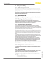
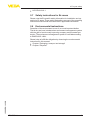
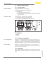
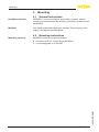
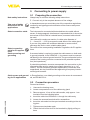
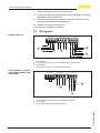
Operating Instructions
VEGADIS 11
Document ID: 19888
Contents
Contents
1 About this document
1.1Function............................................................................................................................ 3
1.2 Target group...................................................................................................................... 3
1.3 Symbols used................................................................................................................... 3
2 For your safety
2.1 Authorised personnel........................................................................................................ 4
2.2 Appropriate use................................................................................................................. 4
2.3 Warning about incorrect use.............................................................................................. 4
2.4 General safety instructions................................................................................................ 4
2.5 Safety label on the instrument........................................................................................... 4
2.6 CE conformity.................................................................................................................... 4
2.7 Safety instructions for Ex areas......................................................................................... 5
2.8 Environmental instructions................................................................................................ 5
3 Product description
3.1 Configuration..................................................................................................................... 6
3.2 Principle of operation........................................................................................................ 6
3.3Operation.......................................................................................................................... 6
3.4 Packaging, transport and storage...................................................................................... 7
4Mounting
4.1 General instructions.......................................................................................................... 8
4.2 Mounting instructions........................................................................................................ 8
5 Connecting to power supply
5.1 Preparing the connection.................................................................................................. 9
5.2 Connection procedure....................................................................................................... 9
5.3 Wiring plan...................................................................................................................... 10
6Setup
6.1 Adjustment system.......................................................................................................... 11
6.2 Indication scaling............................................................................................................ 11
7 Maintenance and fault rectification
7.1Maintenance................................................................................................................... 14
7.2 Rectify faults.................................................................................................................... 14
7.3 How to proceed if a repair is needed............................................................................... 15
8Dismount
8.1 Dismounting steps.......................................................................................................... 16
8.2Disposal.......................................................................................................................... 16
9Supplement
9.1 Technical data................................................................................................................. 17
9.2Dimensions..................................................................................................................... 18
19888-EN-140801
2
VEGADIS 11 •
1 About this document
1 About this document
1.1Function
This operating instructions manual provides all the information you
need for mounting, connection and setup as well as important instructions for maintenance and fault rectification. Please read this information before putting the instrument into operation and keep this manual
accessible in the immediate vicinity of the device.
1.2 Target group
This operating instructions manual is directed to trained specialist
personnel. The contents of this manual should be made available to
these personnel and put into practice by them.
1.3 Symbols used
Information, tip, note
This symbol indicates helpful additional information.
Caution: If this warning is ignored, faults or malfunctions can result.
Warning: If this warning is ignored, injury to persons and/or serious
damage to the instrument can result.
Danger: If this warning is ignored, serious injury to persons and/or
destruction of the instrument can result.
Ex applications
This symbol indicates special instructions for Ex applications.
•
→
1
SIL applications
This symbol indicates instructions for functional safety which must be
taken into account particularly for safety-relevant applications.
List
The dot set in front indicates a list with no implied sequence.
Action
This arrow indicates a single action.
Sequence of actions
Numbers set in front indicate successive steps in a procedure.
19888-EN-140801
Battery disposal
This symbol indicates special information about the disposal of batteries and accumulators.
VEGADIS 11 •
3
2 For your safety
2 For your safety
2.1 Authorised personnel
All operations described in this operating instructions manual must
be carried out only by trained specialist personnel authorised by the
plant operator.
During work on and with the device the required personal protective
equipment must always be worn.
2.2 Appropriate use
VEGADIS 11 is a digital indicating instrument for 4 … 20 mA circuits.
2.3 Warning about incorrect use
Inappropriate or incorrect use of the instrument can give rise to
application-specific hazards, e.g. vessel overfill or damage to system
components through incorrect mounting or adjustment.
2.4 General safety instructions
This is a state-of-the-art instrument complying with all prevailing
regulations and guidelines. The instrument must only be operated in a
technically flawless and reliable condition. The operator is responsible
for the trouble-free operation of the instrument.
During the entire duration of use, the user is obliged to determine the
compliance of the necessary occupational safety measures with the
current valid rules and regulations and also take note of new regulations.
The safety instructions in this operating instructions manual, the national installation standards as well as the valid safety regulations and
accident prevention rules must be observed by the user.
For safety and warranty reasons, any invasive work on the device
beyond that described in the operating instructions manual may be
carried out only by personnel authorised by the manufacturer. Arbitrary conversions or modifications are explicitly forbidden.
The safety approval markings and safety tips on the device must also
be observed.
2.5 Safety label on the instrument
The safety approval markings and safety tips on the device must be
observed.
2.6 CE conformity
Conformity has been judged according to the following standards:
•
4
EMC:
–– Emission EN 50081-1
–– Susceptibility EN 50082-2
VEGADIS 11 •
19888-EN-140801
The instrument is CE conform to EMVG (89/336/EWG), NSR (73/23/
EWG) and corresponds to NAMUR recommendation NE 21.
2 For your safety
•
LVD: EN 61010-1
2.7 Safety instructions for Ex areas
Please note the Ex-specific safety information for installation and operation in Ex areas. These safety instructions are part of the operating
instructions manual and come with the Ex-approved instruments.
2.8 Environmental instructions
Protection of the environment is one of our most important duties.
That is why we have introduced an environment management system
with the goal of continuously improving company environmental protection. The environment management system is certified according
to DIN EN ISO 14001.
Please help us fulfill this obligation by observing the environmental
instructions in this manual:
Chapter "Packaging, transport and storage"
Chapter "Disposal"
19888-EN-140801
•
•
VEGADIS 11 •
5
3 Product description
3 Product description
3.1 Configuration
Scope of delivery
The scope of delivery encompasses:
Constituent parts
The VEGADIS 11 consists of the components:
•
•
•
•
Digital indicating instrument VEGADIS 11
Documentation
–– this operating instructions manual
–– Ex specific safety instructions (with Ex versions), if necessary
further certificates
Housing with integrated adjustment insert
Housing cover with integrated indicating module
1
OPERATE
ZERO
END
POINT
TRANSMITTER
DISPLAY
2
3
4
+ 4...20mA
VEGADIS 12
+
Fig. 1: VEGADIS 11
1 Adjustment insert
2Indication
3Cover
4Housing
3.2 Principle of operation
Area of application
VEGADIS 11 is a digital indicating instrument for measured value
indication in 4 … 20 mA circuits. The measured value is displayed
digitally or as bargraph via the LC display. The digital indication can
be scaled. VEGADIS 11 is suitable for wall and carrier rail mounting.
Voltage supply
VEGADIS 11 is looped directly into the 4 … 20 mA circuits and
requires no separate external energy. Connection is carried out via
screw terminals in the housing.
3.3Operation
6
VEGADIS 11 •
19888-EN-140801
For scaling the indication, VEGADIS 11 is equipped with an adjustment module. Adjustment is carried out via a rotary switch and two
keys.
3 Product description
Packaging
3.4 Packaging, transport and storage
Your instrument was protected by packaging during transport. Its
capacity to handle normal loads during transport is assured by a test
based on ISO 4180.
The packaging of standard instruments consists of environmentfriendly, recyclable cardboard. For special versions, PE foam or PE
foil is also used. Dispose of the packaging material via specialised
recycling companies.
Transport
Transport must be carried out in due consideration of the notes on the
transport packaging. Nonobservance of these instructions can cause
damage to the device.
Transport inspection
The delivery must be checked for completeness and possible transit
damage immediately at receipt. Ascertained transit damage or concealed defects must be appropriately dealt with.
Storage
Up to the time of installation, the packages must be left closed and
stored according to the orientation and storage markings on the
outside.
Unless otherwise indicated, the packages must be stored only under
the following conditions:
•
Not in the open
Dry and dust free
Not exposed to corrosive media
Protected against solar radiation
Avoiding mechanical shock and vibration
Storage and transport temperature see chapter "Supplement Technical data - Ambient conditions"
Relative humidity 20 … 85 %
19888-EN-140801
Storage and transport
temperature
•
•
•
•
•
•
VEGADIS 11 •
7
4 Mounting
4Mounting
4.1 General instructions
Installation position
VEGADIS 11 can be mounted in any position. However, vertical
mounting is recommended. By doing so, penetration of moisture can
be avoided.
Moisture
Use the recommended cables (see chapter "Connecting to power
supply") and tighten the cable gland.
Mounting versions
VEGADIS 11 can be mounted as follows:
4.2 Mounting instructions
•
•
on carrier rail 35 x 7.5 according to EN 50022
on mounting plate or on the wall
19888-EN-140801
8
VEGADIS 11 •
5 Connecting to power supply
5 Connecting to power supply
Note safety instructions
Take note of safety
instructions for Ex
applications
Select connection cable
5.1 Preparing the connection
Always keep in mind the following safety instructions:
•
Connect only in the complete absence of line voltage
In hazardous areas you must take note of the respective regulations,
conformity and type approval certificates of the sensors and power
supply units.
The instrument is connected with standard two-wire cable without
screen. If electromagnetic interference is expected which is above the
test values of EN 61326 for industrial areas, screened cable should
be used.
Use cable with round cross-section. A cable outer diameter of
5 … 9 mm (0.2 … 0.35 in) ensures the seal effect of the cable gland.
If you are using cable with a different diameter or cross-section,
exchange the seal or use a suitable cable gland.
Select connection
cable for Ex applications
Cable screening and
grounding
Take note of the corresponding installation regulations for Ex applications.
If screened cable is required, connect the cable screen on both ends
to ground potential. In the VEGADIS 11, the screen must be connected directly to the internal ground terminal. The ground terminal on the
outside of the housing must be connected to the potential equalisation (low impedance).
If potential equalisation currents are expected, the connection on the
processing side must be made via a ceramic capacitor (e. g. 1 nF,
1500 V). The low-frequency potential equalisation currents are thus
suppressed, but the protective effect against high frequency interference signals remains.
Cable screen and ground- In Ex applications, one-sided grounding on the sensor is recommending for Ex applications
ed, see EN 60079-14.
5.2 Connection procedure
Proceed as follows:
1. Unscrew the housing cover
2. Loosen compression nut of the cable entry gland
3. Remove approx. 10 cm of the cable mantle, strip approx. 1 cm
insulation from the individual wires
4. Insert the cable into VEGADIS 11 through the cable entry
5. Loosen the screwed terminals with a screwdriver
19888-EN-140801
6. Insert the wire ends into the open terminals according to the wiring plan
7. Tighten screw terminals again
8. Check the hold of the wires in the terminals by lightly pulling on
them
VEGADIS 11 •
9
5 Connecting to power supply
9. Connect the screen to the ground terminal
10. Connect the ground terminal outside on the housing according to
specification (low impedance)
11. Tighten the compression nut of the cable entry gland. The seal
ring must completely encircle the cable
12. Screw the housing cover back on
The electrical connection is finished.
Passive sensors
5.3 Wiring plan
OUTPUT
1
2
DISPLAY
3
5
6
1 +-
7
8
4... 20mA
10
11
12
+ 4
3
+ 2
Fig. 2: Wiring plan - passive sensor
1
2
3
4
Active sensors, sensors
with signal conditioning
instrument
To the sensor
For voltage supply or to the processing system (active input)
for indication
Control instrument (4 … 20 mA measurement)
OUTPUT
1
2
DISPLAY
3
5
6
7
8
4... 20mA
10
11
12
+ 3
2
+ -
1
Fig. 3: Wiring plan - active sensor
1 To the sensor or to the signal conditioning instrument
2 for indication
3 To the processing system (passive input)
19888-EN-140801
10
VEGADIS 11 •
6 Setup
6Setup
Adjustment elements
6.1 Adjustment system
1
2
OPERATE
ZERO
END
POINT
1 2 3
TRANSMITTER
3
5 6 7 8
DISPLAY
10 11 12
+
-
4...20mA
-
+
VEGADIS 12
Fig. 4: Adjustment elements of VEGADIS 11
1 Rotary switch: choose the requested function
2 [+] key, change value (rising)
3 [-] key, change value (falling)
Adjustment volume
Adjustment system
• operate - operation
• zero - adjustment of the min. value (4 mA)
• span - adjustment of the max. value (20 mA)
• point - shifting of the decimal point
• The desired function is selected with the rotary switch
• With the [+] and [-] keys the signal current or the integration time is
•
set or the indication is scaled
The respective rotary switch is finally set to position "OPERATE"
The set values are transmitted to the EEPROM memory and remain
there even in case of voltage loss.
6.2 Indication scaling
For scaling the indication, it is recommended to screw the housing
cover laterally or displaced to the bottom on the housing.
19888-EN-140801
Preparation
VEGADIS 11 •
11
6 Setup
1
OPERATE
ZERO
END
POINT
1
2
3
4
5
TRANSMITTER
6
7
8
DISPLAY
VEGADIS 11
+
-
10
11
+ 4...20mA
12
+
2
Fig. 5: With an individual instrument
1 Indicating module
2 Fixing screws
OPERATE
ZERO
END
POINT
TRANSMITTER
1
DISPLAY
+
-
+
4...20mA
+
2
Fig. 6: With several instruments mounted next to each other
1 Indicating module
2 Fixing screws
19888-EN-140801
12
VEGADIS 11 •
6 Setup
Display elements
2
1
3
Fig. 7: Indicating elements of VEGADIS 11
1 Bar graph
2 Tendency indication
3 Digital value
•
•
four positions as well as signa and decimal point
individual scaling between -9999 … +9999
The display outputs the current 4 … 20 mA as bar graph and digital
value.
With 4 mA no segment of the bar graph appears, with 20 mA all segments appear. This assignment is fix.
You can scale the digital value to any value between -9999 … +9999
via the adjustment module.
Adjustment steps, scaling To scale the indication, proceed as follows:
1. Initial value: Set rotary switch to "zero"
2. Set the requested value, e.g. 0 with the [+] and [-] keys
3. Final value: Set the rotary switch to "span"
4. Set the requested value, e.g. 1000 with the [+] and [-] keys
5. Decimal point: Set the rotary switch to "point"
6. With the [+] and [-] keys you can adjust the requested value, e.g.
8888 (no decimal point)
7. Set rotary switch to "OPERATE"
8. Screw the housing cover back on
19888-EN-140801
The adjustment data are effective, the output current 4 … 20 mA corresponds to the actual level.
VEGADIS 11 •
13
7 Maintenance and fault rectification
7 Maintenance and fault rectification
7.1Maintenance
If the instrument is used properly, no special maintenance is required
in normal operation.
7.2 Rectify faults
Reaction when malfunctions occur
The operator of the system is responsible for taking suitable measures to rectify faults.
Causes of malfunction
VEGADIS 11 offers maximum reliability. Nevertheless, faults can occur during operation. These may be caused by the following, e.g.:
•
•
•
•
24 hour service hotline
Check the 4 … 20 mA
signal
Sensor
Process
Voltage supply
Signal processing
Should these measures not be successful, please call in urgent cases
the VEGA service hotline under the phone no. +49 1805 858550.
The hotline is manned 7 days a week round-the-clock. Since we offer
this service worldwide, the support is only available in the English
language. The service is free, only standard call charges are incurred.
Connect a multimeter in the suitable measuring range according to
the wiring plan.
Error code
Cause
Rectification
4 … 20 mA
signal not
stable
Level fluctuations
–– Adjust integration time via PACTware
4 … 20 mA
signal missing
Wrong connection to
voltage supply
–– Check connection according to
chapter "Connection steps" and
if necessary, correct according to
chapter "Wiring plan"
No power supply
–– Check cables for breaks; repair if
necessary
No atmospheric pres- –– Check pressure compensation
sure compensation
with pressure transmitters
Operating voltage
–– Check, adapt if necessary
too low or load resistance too high
Current signal 3.6 mA;
22 mA
Electronics module in –– Exchange the instrument or send it
the sensor defective
in for repair
Reaction after fault rectification
14
Depending on the reason for the fault and the measures taken, the
steps described in chapter "Set up" may have to be carried out again.
VEGADIS 11 •
19888-EN-140801
In Ex applications, the regulations for the wiring of intrinsically safe
circuits must be observed.
7 Maintenance and fault rectification
7.3 How to proceed if a repair is needed
You can find a repair form as well as detailed information on how to
proceed at www.vega.com/downloads and "Forms and certificates".
By doing this you help us carry out the repair quickly and without having to call back for needed information.
If a repair is necessary, please proceed as follows:
•
•
•
19888-EN-140801
•
Print and fill out one form per instrument
Clean the instrument and pack it damage-proof
Attach the completed form and, if need be, also a safety data
sheet outside on the packaging
Please contact the agency serving you to get the address for
the return shipment. You can find the agency on our home page
www.vega.com.
VEGADIS 11 •
15
8 Dismount
8Dismount
8.1 Dismounting steps
Warning:
Before dismounting, be aware of dangerous process conditions such
as e.g. pressure in the vessel or pipeline, high temperatures, corrosive or toxic products etc.
Take note of chapters "Mounting" and "Connecting to power supply"
and carry out the listed steps in reverse order.
8.2Disposal
The instrument consists of materials which can be recycled by specialised recycling companies. We use recyclable materials and have
designed the parts to be easily separable.
WEEE directive 2002/96/EG
This instrument is not subject to the WEEE directive 2002/96/EG and
the respective national laws. Pass the instrument directly on to a specialised recycling company and do not use the municipal collecting
points. These may be used only for privately used products according
to the WEEE directive.
Correct disposal avoids negative effects on humans and the environment and ensures recycling of useful raw materials.
Materials: see chapter "Technical data"
If you have no way to dispose of the old instrument properly, please
contact us concerning return and disposal.
19888-EN-140801
16
VEGADIS 11 •
9 Supplement
9Supplement
9.1
Technical data
General data
316L corresponds to 1.4404 or 1.4435, 316Ti corresponds to 1.4571
Materials
ƲƲ Housing
ƲƲ Ground terminal
ƲƲ Inspection window of the indication
316Ti/316L
Weight
approx. 0.5 kg (1.102 lbs)
Ambient conditions
Ambient temperature
-20 … +70 °C (-40 … +158 °F)
Electromechanical data
Cable gland
2 x cable entry M20 x 1.5 (cable: ø 5 … 9 mm)
Adjustment and display elements
Adjustment elements
2 keys, 1 rotary switch
Storage and transport temperature
Screw terminals for cable cross-section
up to
Indication
Measured value indication
-40 … +85 °C (-40 … +185 °F)
2.5 mm² (AWG 14)
LC multiple function display with bar graph, digital value
4-digit and tendency indicator for rising or falling values
ƲƲ Number of figures - digital value
4
ƲƲ Number of segments - bar graph
20
ƲƲ Size of digits
W x H = 5.5 x 10 mm
Voltage supply
Voltage supply
via the signal circuit
Voltage loss with 20 mA
approx. 4.5 V
Max. input current
Current range
150 mA
3.5 … 22.5 mA1)
Electrical protective measures
Protection rating
IP 66
Protection class
III
Overvoltage category
19888-EN-140801
plastic PBT
Approvals2)
ATEX ia
1)
2)
III
ATEX II 2G EEx ia IIC T6
The indication remains dark if the loop current is not sufficient for operation.
Deviating data in Ex applications: see separate safety instructions.
VEGADIS 11 •
17
9 Supplement
9.2Dimensions
VEGADIS 11
108mm (4 1/4")
118mm (4 41/64")
135mm (5 5/16")
85mm (3 11/32")
82mm (3 15/64")
ø
( 13 5m
/6 m
4"
)
38mm
(1 1/2")
M20x1,5
Fig. 8: VEGADIS 11, size of digits W x H = approx. 5 x 9 mm
19888-EN-140801
18
VEGADIS 11 •
9 Supplement
9.3
Industrial property rights
VEGA product lines are global protected by industrial property rights. Further information see
www.vega.com.
Only in U.S.A.: Further information see patent label at the sensor housing.
VEGA Produktfamilien sind weltweit geschützt durch gewerbliche Schutzrechte.
Nähere Informationen unter www.vega.com.
Les lignes de produits VEGA sont globalement protégées par des droits de propriété intellectuelle. Pour plus d'informations, on pourra se référer au site www.vega.com.
VEGA lineas de productos están protegidas por los derechos en el campo de la propiedad industrial. Para mayor información revise la pagina web www.vega.com.
Линии продукции фирмы ВЕГА защищаются по всему миру правами на интеллектуальную
собственность. Дальнейшую информацию смотрите на сайте www.vega.com.
VEGA系列产品在全球享有知识产权保护。
进一步信息请参见网站<www.vega.com。
9.4Trademark
19888-EN-140801
All the brands as well as trade and company names used are property of their lawful proprietor/
originator.
VEGADIS 11 •
19
All statements concerning scope of delivery, application, practical use and operating conditions of the sensors and processing systems correspond to the information
available at the time of printing.
Subject to change without prior notice
© VEGA Grieshaber KG, Schiltach/Germany 2014
VEGA Grieshaber KG
Am Hohenstein 113
77761 Schiltach
Germany
Phone +49 7836 50-0
Fax +49 7836 50-201
E-mail: [email protected]
www.vega.com
19888-EN-140801
Printing date: