1
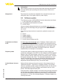
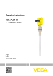
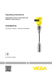
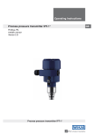
Operating Instructions
Ultrasonic sensor for continuous level
measurement
VEGASON 62
Foundation Fieldbus
Document ID: 28791
Contents
Contents
1 About this document
1.1Function............................................................................................................................ 4
1.2 Target group...................................................................................................................... 4
1.3 Symbols used................................................................................................................... 4
2 For your safety
2.1 Authorised personnel........................................................................................................ 5
2.2 Appropriate use................................................................................................................. 5
2.3 Warning about incorrect use.............................................................................................. 5
2.4 General safety instructions................................................................................................ 5
2.5 Safety label on the instrument........................................................................................... 6
2.6 CE conformity.................................................................................................................... 6
2.7 Fulfillment of NAMUR recommendations.......................................................................... 6
2.8 Safety instructions for Ex areas......................................................................................... 6
2.9 Environmental instructions................................................................................................ 6
3 Product description
3.1 Configuration..................................................................................................................... 7
3.2 Principle of operation........................................................................................................ 7
3.3Operation.......................................................................................................................... 8
3.4 Packaging, transport and storage...................................................................................... 8
4Mounting
4.1 General instructions........................................................................................................ 10
4.2 Mounting instructions...................................................................................................... 11
5 Connecting to power supply
5.1 Preparing the connection................................................................................................ 18
5.2 Connection procedure..................................................................................................... 19
5.3 Wiring plan, single chamber housing.............................................................................. 20
5.4 Wiring plan, double chamber housing............................................................................. 21
5.5 Wiring plan - version IP 66/IP 68, 1 bar............................................................................ 23
5.6 Switch-on phase............................................................................................................. 24
6 Set up with the display and adjustment module PLICSCOM
6.1 Short description............................................................................................................. 25
6.2 Insert display and adjustment module............................................................................. 25
6.3 Adjustment system.......................................................................................................... 26
6.4 Setup steps..................................................................................................................... 27
6.5 Menu schematic.............................................................................................................. 32
6.10 Saving the parameter adjustment data............................................................................ 33
8 Maintenance and fault rectification
8.1 Maintenance................................................................................................................... 37
8.2 Rectify faults.................................................................................................................... 37
8.3 Exchanging the electronics module................................................................................. 38
2
VEGASON 62 • Foundation Fieldbus
28791-EN-141015
7 Set up with PACTware and other adjustment programs
7.1 Connect the PC via VEGACONNECT............................................................................. 34
7.2 Parameter adjustment with PACTware............................................................................. 35
7.3 Parameter adjustment with AMS™................................................................................. 36
7.4 Saving the parameter adjustment data............................................................................ 36
Contents
8.4
8.5
Software update.............................................................................................................. 39
How to proceed if a repair is needed............................................................................... 40
9Dismount
9.1 Dismounting steps.......................................................................................................... 41
9.2Disposal.......................................................................................................................... 41
10Supplement
10.1 Technical data................................................................................................................. 42
10.2 Foundation Fieldbus........................................................................................................ 46
10.3Dimensions..................................................................................................................... 50
Supplementary documentation
Information:
Supplementary documents appropriate to the ordered version come
with the delivery. You can find them listed in chapter "Product description".
Instructions manuals for accessories and replacement parts
28791-EN-141015
Tip:
To ensure reliable setup and operation of your VEGASON 62, we offer
accessories and replacement parts. The corresponding documentations are:
•
•
•
•
•
27835 - Display and adjustment module PLICSCOM
32628 - Interface adapter VEGACONNECT
27720 - External indication VEGADIS 61
34296 - Protective cover
30176 - Electronics module VEGASON series 60
Editing status: 2014-02-28
VEGASON 62 • Foundation Fieldbus
3
1 About this document
1 About this document
1.1Function
This operating instructions manual provides all the information you
need for mounting, connection and setup as well as important instructions for maintenance and fault rectification. Please read this information before putting the instrument into operation and keep this manual
accessible in the immediate vicinity of the device.
1.2 Target group
This operating instructions manual is directed to trained specialist
personnel. The contents of this manual should be made available to
these personnel and put into practice by them.
1.3 Symbols used
Information, tip, note
This symbol indicates helpful additional information.
Caution: If this warning is ignored, faults or malfunctions can result.
Warning: If this warning is ignored, injury to persons and/or serious
damage to the instrument can result.
Danger: If this warning is ignored, serious injury to persons and/or
destruction of the instrument can result.
Ex applications
This symbol indicates special instructions for Ex applications.
•
→
1
SIL applications
This symbol indicates instructions for functional safety which must be
taken into account particularly for safety-relevant applications.
List
The dot set in front indicates a list with no implied sequence.
Action
This arrow indicates a single action.
Sequence of actions
Numbers set in front indicate successive steps in a procedure.
Battery disposal
This symbol indicates special information about the disposal of batteries and accumulators.
28791-EN-141015
4
VEGASON 62 • Foundation Fieldbus
2 For your safety
2 For your safety
2.1 Authorised personnel
All operations described in this operating instructions manual must
be carried out only by trained specialist personnel authorised by the
plant operator.
During work on and with the device the required personal protective
equipment must always be worn.
2.2 Appropriate use
VEGASON 62 is a sensor for continuous level measurement.
You can find detailed information about the area of application in
chapter "Product description".
Operational reliability is ensured only if the instrument is properly
used according to the specifications in the operating instructions
manual as well as possible supplementary instructions.
For safety and warranty reasons, any invasive work on the device
beyond that described in the operating instructions manual may be
carried out only by personnel authorised by the manufacturer. Arbitrary conversions or modifications are explicitly forbidden.
2.3 Warning about incorrect use
Inappropriate or incorrect use of the instrument can give rise to
application-specific hazards, e.g. vessel overfill or damage to system
components through incorrect mounting or adjustment.
2.4 General safety instructions
This is a state-of-the-art instrument complying with all prevailing
regulations and guidelines. The instrument must only be operated in a
technically flawless and reliable condition. The operator is responsible
for the trouble-free operation of the instrument.
During the entire duration of use, the user is obliged to determine the
compliance of the necessary occupational safety measures with the
current valid rules and regulations and also take note of new regulations.
The safety instructions in this operating instructions manual, the national installation standards as well as the valid safety regulations and
accident prevention rules must be observed by the user.
28791-EN-141015
For safety and warranty reasons, any invasive work on the device
beyond that described in the operating instructions manual may be
carried out only by personnel authorised by the manufacturer. Arbitrary conversions or modifications are explicitly forbidden.
The safety approval markings and safety tips on the device must also
be observed.
VEGASON 62 • Foundation Fieldbus
5
2 For your safety
2.5 Safety label on the instrument
The safety approval markings and safety tips on the device must be
observed.
2.6 CE conformity
The device fulfills the legal requirements of the applicable EC guidelines. By affixing the CE marking, we confirm successful testing of the
product.
2.7 Fulfillment of NAMUR recommendations
NAMUR is the automation technology user association in the process
industry in Germany. The published NAMUR recommendations are
accepted as the standard in field instrumentation.
The device fulfills the requirements of the following NAMUR recommendations:
•
•
•
NE 21 – Electromagnetic compatibility of equipment
NE 43 – Signal level for malfunction information from measuring
transducers
NE 53 – Compatibility of field devices and display/adjustment
components
For further information see www.namur.de.
2.8 Safety instructions for Ex areas
Please note the Ex-specific safety information for installation and operation in Ex areas. These safety instructions are part of the operating
instructions manual and come with the Ex-approved instruments.
2.9 Environmental instructions
Protection of the environment is one of our most important duties.
That is why we have introduced an environment management system
with the goal of continuously improving company environmental protection. The environment management system is certified according
to DIN EN ISO 14001.
Please help us fulfill this obligation by observing the environmental
instructions in this manual:
•
•
Chapter "Packaging, transport and storage"
Chapter "Disposal"
28791-EN-141015
6
VEGASON 62 • Foundation Fieldbus
3 Product description
3 Product description
3.1 Configuration
Scope of delivery
The scope of delivery encompasses:
Constituent parts
The VEGASON 62 consists of the components:
•
•
•
•
•
VEGASON 62 ultrasonic sensor
Documentation
–– this operating instructions manual
–– Operating instructions manual 27835 "Display and adjustment
module PLICSCOM" (optional)
–– Supplementary instructions manual 31708 "Heating for display
and adjustment module" (optional)
–– Supplementary instructions manual "Plug connector" (optional)
–– Ex-specific "Safety instructions" (with Ex versions)
–– if necessary, further certificates
Process fitting with transducer
Housing with electronics, optionally available with plug connector
Housing cover, optionally available with display and adjustment
module PLICSCOM
The components are available in different versions.
1
2
3
Fig. 1: VEGASON 62 - threaded version with plastic housing
28791-EN-141015
1 Housing cover with integrated PLICSCOM (optional)
2 Housing with electronics
3 Process fitting with transducer
Application area
3.2 Principle of operation
VEGASON 62 is an ultrasonic sensor for continuous level measurement. It is suitable for liquids and solids in virtually all industries,
particularly in the water and waste water industry.
VEGASON 62 • Foundation Fieldbus
7
3 Product description
Functional principle
The transducer of the ultrasonic sensor transmits short ultrasonic
pulses to the measured product. These pulses are reflected by
product surface and received back by the transducer as echoes.
The running time of the ultrasonic pulses from emission to reception
is proportional to the distance and hence the level. The determined
level is converted into an appropriate output signal and outputted as
measured value.
Power supply and bus
communication
Power is supplied via the H1 Fieldbus. A two-wire cable according to
Fieldbus specification serves as carrier of both power and digital data
for multiple sensors. This cable can be operated in two versions:
•
•
DD/CFF
via an H1 interface card in the control system and additional power
supply
via a Linking device with HSE (High speed Ethernet) and additional power supply according to IEC 61158-2
The DD (Device Descriptions) and CFF (capability files) necessary
for planning and configuration of your FF (Foundation Fieldbus) communication network are available in the download area of the VEGA
homepage www.vega.com under "Services - Downloads - Software
- Foundation Fieldbus". The appropriate certificates are also available
there. A CD with the appropriate files and certificates can be ordered
via e-mail under [email protected] or by phone from one of the
VEGA agencies under the order number "DRIVER.S".
The backlight of the display and adjustment module is powered by the
sensor. Prerequisite is a certain level of operating voltage.
The data for power supply are specified in chapter "Technical data".
The optional heating requires its own operating voltage. You can find
details in the supplementary instructions manual "Heating for display
and adjustment module".
This function is generally not available for approved instruments.
3.3Operation
The instrument can be adjusted with the following adjustment media:
•
•
•
Packaging
With the display and adjustment module
with the suitable VEGA DTM in conjunction with an adjustment
software according to the FDT/DTM standard, e.g. PACTware and
PC
a configuration tool
3.4 Packaging, transport and storage
The packaging of standard instruments consists of environmentfriendly, recyclable cardboard. For special versions, PE foam or PE
foil is also used. Dispose of the packaging material via specialised
recycling companies.
8
VEGASON 62 • Foundation Fieldbus
28791-EN-141015
Your instrument was protected by packaging during transport. Its
capacity to handle normal loads during transport is assured by a test
based on ISO 4180.
3 Product description
Transport
Transport must be carried out in due consideration of the notes on the
transport packaging. Nonobservance of these instructions can cause
damage to the device.
Transport inspection
The delivery must be checked for completeness and possible transit
damage immediately at receipt. Ascertained transit damage or concealed defects must be appropriately dealt with.
Storage
Up to the time of installation, the packages must be left closed and
stored according to the orientation and storage markings on the
outside.
Unless otherwise indicated, the packages must be stored only under
the following conditions:
•
Not in the open
Dry and dust free
Not exposed to corrosive media
Protected against solar radiation
Avoiding mechanical shock and vibration
Storage and transport temperature see chapter "Supplement Technical data - Ambient conditions"
Relative humidity 20 … 85 %
28791-EN-141015
Storage and transport
temperature
•
•
•
•
•
•
VEGASON 62 • Foundation Fieldbus
9
4 Mounting
4Mounting
4.1 General instructions
Suitability for the process Make sure that all parts of the instrument coming in direct contact
conditions
with the process, especially the sensor element, process seal and
process fitting, are suitable for the existing process conditions, such
as process pressure, process temperature as well as the chemical
properties of the medium.
You can find the specifications in chapter "Technical data" and on the
nameplate.
Installation position
Select an installation position you can easily reach for mounting and
connecting as well as later retrofitting of a display and adjustment
module. The housing can be rotated by 330° without the use of any
tools. You can also install the display and adjustment module in four
different positions (each displaced by 90°).
Moisture
Use the recommended cables (see chapter "Connecting to power
supply") and tighten the cable gland.
You can give your instrument additional protection against moisture
penetration by leading the connection cable downward in front of the
cable entry. Rain and condensation water can thus drain off. This applies mainly to outdoor mounting as well as installation in areas where
high humidity is expected (e.g. through cleaning processes) or on
cooled or heated vessels.
Fig. 2: Measures against moisture ingress
Measuring range
The reference plane for the measuring range is the lower edge of the
transducer.
Make sure that a minimum distance from the reference plane - the
so-called dead zone, in which measurement is not possible - is
maintained. The exact value of the dead zone is stated in chapter
"Technical data".
28791-EN-141015
10
VEGASON 62 • Foundation Fieldbus
4 Mounting
1
2
Fig. 3: Minimum distance to the max. level
1 Dead zone
2 Reference plane
Information:
If the medium reaches the transducer, buildup can form on it and
cause faulty measurements later on.
1
2
3
100%
0%
Fig. 4: Measuring range (operating range) and max. measuring distance
1full
2 empty (max. measuring distance)
3 Measuring range
28791-EN-141015
Pressure/Vacuum
Screwing in
Gauge pressure in the vessel does not influence VEGASON 62. Low
pressure or vacuum does, however, damp the ultrasonic pulses. This
influences the measuring result, particularly if the level is very low.
With pressures under -0.2 bar (-20 kPa) you should use a different
measuring principle, e.g. radar or guided microwave.
4.2 Mounting instructions
Screw VEGASON 62 into the mounting socket with an appropriate
spanner applied to the hexagon of the process fitting. Max. torque see
chapter "Technical data".
VEGASON 62 • Foundation Fieldbus
11
4 Mounting
Warning:
The housing must not be used to screw the instrument in! Applying
tightening force can damage internal parts of the housing.
Installation position
When mounting the sensor, keep a distance of at least 200 mm
(7.874 in) to the vessel wall. If the sensor is installed in the center of
dished or round vessel tops, multiple echoes can arise. These can,
however, be suppressed by an appropriate adjustment (see chapter
"Setup").
2
1
> 200 mm
Fig. 5: Mounting on round vessel tops
1 Reference plane
2 Vessel center or symmetry axis
If this distance cannot be maintained, a false signal storage should
be carried out during setup. This applies particularly if buildup on the
vessel wall is expected. In such cases, we recommend repeating the
false signal storage at a later date with existing buildup.
In vessels with conical bottom it can be advantageous to mount the
sensor in the center of the vessel, as measurement is then possible
down to the lowest point of the vessel bottom.
28791-EN-141015
12
VEGASON 62 • Foundation Fieldbus
4 Mounting
Fig. 6: Vessel with conical bottom
Socket pieces should be dimensioned so that the lower end of the
transducer protrudes at least 10 mm (0.394 in) out of the socket.
ca. 10 mm
Socket
Fig. 7: Recommended socket mounting
28791-EN-141015
If the reflective properties of the medium are good, you can mount
VEGASON 62 on sockets which are higher than the length of the
transducer. You will find recommended values for socket heights in the
following illustration. The socket end should be smooth and burr-free,
if possible also rounded. Carry out a false echo storage.
VEGASON 62 • Foundation Fieldbus
13
4 Mounting
h
d
100 mm/4"
150 mm/6"
200 mm/8"
h
300 mm/12"
400 mm/16"
500 mm/20"
d
Fig. 8: Deviating socket dimensions
Sensor orientation
In liquids, direct the sensor as perpendicular as possible to the product surface to achieve optimum measurement results.
Fig. 9: Alignment in liquids
00
x4
00
~4
45°
To reduce the min. distance to the medium, you can also mount VEGASON 62 with a beam deflector. By doing this, it is possible to fill the
vessel nearly to maximum. Such an arrangement is suitable primarily
for open vessels such as e.g. overflow basins.
~200
Fig. 10: Beam deflector
Vessel installations
The ultrasonic sensor should be installed at a location where no
installations cross the ultrasonic beam.
In case of existing vessel installations, a false echo storage should be
carried out during setup.
14
VEGASON 62 • Foundation Fieldbus
28791-EN-141015
Vessel installations such as for example, ladders, limit switches, heating spirals, struts etc. can cause false echoes that interfere with the
useful echo. Make sure when planning your measuring site that the
ultrasonic signals have a "clear view" to the measured product.
4 Mounting
If large vessel installations such as struts or supports cause false
echoes, these can be attenuated through supplementary measures.
Small, inclined sheet metal or plastic baffles above the installations
scatter the ultrasonic signals and avoid direct false echoes.
α
α
α
α
α
α
Fig. 11: Cover flat, large-area profiles with deflectors
Agitators
If there are agitators in the vessel, a false signal storage should be
carried out with the agitators in motion. This ensures that the interfering reflections from the agitators are saved with the blades in different
positions.
Fig. 12: Agitators
Do not mount the instruments in or above the filling stream. Make sure
that you detect the product surface, not the inflowing product.
28791-EN-141015
Inflowing medium
VEGASON 62 • Foundation Fieldbus
15
4 Mounting
Fig. 13: Inflowing liquid
Foam
Through the action of filling, stirring and other processes in the vessel,
dense foams which considerably damp the emitted signals may form
on the product surface.
If foams are causing measurement errors, the sensor should be used
in a standpipe or, alternatively, the more suitable guided radar sensors (TDR) should be used.
Guided wave radar is unaffected by foam generation and is particularly suitable for such applications.
Air turbulences
If there are strong air currents in the vessel, e.g. due to strong winds
in outdoor installations or air turbulence, e.g. by cyclone extraction
you should mount VEGASON 62 in a standpipe or use a different
measuring principle, e.g. radar or guided radar (TDR).
Standpipe measurement
By using a standpipe (surge or bypass tube), the influence of vessel
installations, foam generation and turbulence is excluded.
Standpipes must extend all the way down to the requested min. level,
as measurement is only possible within the tube.
28791-EN-141015
16
VEGASON 62 • Foundation Fieldbus
4 Mounting
max.
1
min.
Fig. 14: Standpipe in the tank
1 Vent hole: ø 5 … 10 mm (0.197 … 0.394 in)
VEGASON 62 can be used from tube diameters of 50 mm (1.969 in).
Avoid large gaps and thick welding joints when connecting the tubes.
Generally carry out a false echo storage.
28791-EN-141015
Measurement in a standpipe is not recommended for extremely
adhesive products.
VEGASON 62 • Foundation Fieldbus
17
5 Connecting to power supply
5 Connecting to power supply
Safety instructions
5.1 Preparing the connection
Always keep in mind the following safety instructions:
•
•
Connect only in the complete absence of line voltage
If overvoltage surges are expected, overvoltage arresters should
be installed according to Foundation Fieldbus specification
Tip:
We recommend VEGA overvoltage arrester B63-32.
In hazardous areas you must take note of the respective regulations,
conformity and type approval certificates of the sensors and power
supply units.
Voltage supply
The instrument requires a operating voltage of 9 … 32 V DC. Operating voltage and the digital bus signal are carried on the same two-wire
connection cable. Power is supplied via the H1 power supply.
Connection cable
Connection is carried out with screened cable according to Fieldbus
specification.
Use cable with round cross-section. A cable outer diameter of
5 … 9 mm (0.2 … 0.35 in) ensures the seal effect of the cable gland.
If you are using cable with a different diameter or cross-section,
exchange the seal or use a suitable cable gland.
Make sure that the entire installation is carried out according to the
Fieldbus specification. In particular, make sure that the bus is terminated with suitable terminating resistors.
Cable gland ½ NPT
On the instrument with cable entry ½ NPT and plastic housing there is
a metallic ½" threaded insert moulded into the plastic housing.
Caution:
No grease should be used when screwing the NPT cable gland or
steel tube into the threaded insert. Standard grease can contain
additives that corrode the connection between threaded insert and
housing. This would influence the stability of the connection and the
tightness of the housing.
Cable screening and
grounding
In systems with potential equalisation, connect the cable screen
directly to ground potential at the power supply unit, in the connection
box and at the sensor. The screen in the sensor must be connected
directly to the internal ground terminal. The ground terminal outside
on the housing must be connected to the potential equalisation (low
impedance).
18
VEGASON 62 • Foundation Fieldbus
28791-EN-141015
In systems without potential equalisation, connect the cable screen
directly to ground potential at the power supply unit and at the sensor.
In the connection box or T-distributor, the screen of the short stub to
the sensor must not be connected to ground potential or to another
cable screen. The cable screens to the power supply unit and to the
next distributor must be connected to each other and also connected
to ground potential via a ceramic capacitor (e.g. 1 nF, 1500 V). The
5 Connecting to power supply
low frequency potential equalisation currents are thus suppressed,
but the protective effect against high frequency interference signals
remains.
The total capacitance of the cable and of all capacitors must not
exceed 10 nF in Ex applications.
Take note of the corresponding installation regulations for Ex applications. In particular, make sure that no potential equalisation currents
flow over the cable screen. In case of grounding on both sides this
can be achieved by the use of a capacitor or a separate potential
equalisation.
5.2 Connection procedure
Proceed as follows:
1. Unscrew the housing cover
2. If a display and adjustment module is installed, remove it by turning it to the left.
3. Loosen compression nut of the cable entry gland
4. Remove approx. 10 cm (4 in) of the cable mantle, strip approx.
1 cm (0.4 in) of insulation from the ends of the individual wires
5. Insert the cable into the sensor through the cable entry
6. Lift the opening levers of the terminals with a screwdriver (see
following illustration)
28791-EN-141015
7. Insert the wire ends into the open terminals according to the wiring plan
Fig. 15: Connection steps 6 and 7
8. Press down the opening levers of the terminals, you will hear the
terminal spring closing
9. Check the hold of the wires in the terminals by lightly pulling on
them
VEGASON 62 • Foundation Fieldbus
19
5 Connecting to power supply
10. Connect the screen to the internal ground terminal, connect the
outer ground terminal to potential equalisation
11. Tighten the compression nut of the cable entry gland. The seal
ring must completely encircle the cable
12. Screw the housing lid back on
The electrical connection is finished.
5.3 Wiring plan, single chamber housing
Housing overview
The following illustrations apply to the non-Ex as well as to the Ex-ia
version.
5
5
1
5
5
2
3
4
Fig. 16: Material versions, single chamber housing
1Plastic
2Aluminium
3 Stainless steel, precision casting
4 Stainless steel, electro-polished
5 Filter element for air pressure compensation of all material versions. Blind
plug with version IP 66/IP 68, 1 bar for Aluminium and stainless steel
28791-EN-141015
20
VEGASON 62 • Foundation Fieldbus
5 Connecting to power supply
Electronics and terminal
compartment
Typ:
Bus
Display
Sim.
5
1
4
2
1
I²C
5 6 7 8
2
3
Fig. 17: Electronics and terminal compartment, single chamber housing
1 Plug connector for VEGACONNECT (I²C interface)
2 Spring-loaded terminals for connection of the external indication VEGADIS
61
3 Ground terminal for connection of the cable screen
4 Spring-loaded terminals for Foundation Fieldbus connection
5 Simulation switch ("on" = simulation mode)
Wiring plan
Display
I2C
1
2
5
6
7
8
1
Fig. 18: Wiring plan, single chamber housing
1 Voltage supply, signal output
5.4 Wiring plan, double chamber housing
28791-EN-141015
The following illustrations apply to the non-Ex as well as to the Ex-ia
version.
VEGASON 62 • Foundation Fieldbus
21
5 Connecting to power supply
Housing overview
1
2
3
5
4
Fig. 19: Double chamber housing
1
2
3
4
5
Housing cover, connection compartment
Blind plug or plug M12 x 1 for VEGADIS 61 (optional)
Housing cover, electronics compartment
Filter element for air pressure compensation
Cable gland
Electronics compartment
1
Typ:
Sim.
Bus
1
2
Display
I²C
2
5 6 7 8
3
Fig. 20: Electronics compartment, double chamber housing
1 Simulation switch ("on" = simulation mode)
2 Connection for VEGACONNECT (I²C interface)
3 Internal connection cable to the connection compartment
28791-EN-141015
22
VEGASON 62 • Foundation Fieldbus
5 Connecting to power supply
Display
Terminal compartment
2
1
1
2
I2C
3
Fig. 21: Terminal compartment, double chamber housing
1 Spring-loaded terminals for voltage supply
2 Plug connector for VEGACONNECT (I²C interface)
3 Ground terminal for connection of the cable screen
Wiring plan
I2C
1
2
1
Fig. 22: Wiring plan, double chamber housing
1 Voltage supply, signal output
Wire assignment, connection cable
5.5 Wiring plan - version IP 66/IP 68, 1 bar
1
2
28791-EN-141015
Fig. 23: Wire assignment, connection cable
1 brown (+) and blue (-) to power supply or to the processing system
2Shielding
VEGASON 62 • Foundation Fieldbus
23
5 Connecting to power supply
Switch-on phase
5.6 Switch-on phase
After VEGASON 62 is connected to voltage supply or after voltage
recurrence, the instrument carries out a self-check for approx. 30
seconds. The following steps are carried out:
•
•
•
Internal check of the electronics
Indication of the instrument type, the firmware as well as the sensor TAGs (sensor designation)
Status byte goes briefly to fault value
Then the current measured value will be displayed and the corresponding digital output signal will be outputted to the cable.1)
24
The values correspond to the actual measured level as well as to the settings
already carried out, e.g. default setting.
VEGASON 62 • Foundation Fieldbus
28791-EN-141015
1)
6 Set up with the display and adjustment module PLICSCOM
6 Set up with the display and adjustment
module PLICSCOM
Function/Configuration
6.1 Short description
The display and adjustment module is used for measured value
display, adjustment and diagnosis. It can be mounted in the following
housing versions and instruments:
•
•
All sensors of the plics® instrument family, in the single as well as
in the double chamber housing (optionally in the electronics or
connection compartment)
External display and adjustment unit VEGADIS 61
From a hardware version …- 01 or higher of PLICSCOM as well as a
hardware version …- 01, 03 or higher of the corresponding sensor, an
integrated backlight can be switched on via the adjustment menu. The
hardware version is stated on the type label of the PLICSCOM or the
sensor electronics.
Note:
You can find detailed information on adjustment in the operating
instructions manual "Display and adjustment module".
Mount/Dismount display
and adjustment module
6.2 Insert display and adjustment module
The display and adjustment module can be inserted into the sensor
and removed again at any time. It is not necessary to interrupt the
power supply.
Proceed as follows:
1. Unscrew the housing cover
2. Place the display and adjustment module in the desired position
on the electronics (you can choose any one of four different positions - each displaced by 90°)
3. Press the display and adjustment module onto the electronics
and turn it to the right until it snaps in.
4. Screw housing cover with inspection window tightly back on
Disassembly is carried out in reverse order.
28791-EN-141015
The display and adjustment module is powered by the sensor, an additional connection is not necessary.
VEGASON 62 • Foundation Fieldbus
25
6 Set up with the display and adjustment module PLICSCOM
Fig. 24: Insert display and adjustment module
Note:
If you intend to retrofit the instrument with a display and adjustment
module for continuous measured value indication, a higher cover with
an inspection glass is required.
6.3 Adjustment system
2
1
1.1
3
1 LC display
2 Indication of the menu item number
3 Adjustment keys
Key functions
26
•
[OK] key:
VEGASON 62 • Foundation Fieldbus
28791-EN-141015
Fig. 25: Display and adjustment elements
6 Set up with the display and adjustment module PLICSCOM
•
•
•
Adjustment system
Parameter adjustment
––
––
––
––
Move to the menu overview
Confirm selected menu
Edit parameter
Save value
[->] key to select:
–– Menu change
–– Select list entry
–– Select editing position
[+] key:
–– Change value of the parameter
[ESC] key:
–– Interrupt input
–– Jump to next higher menu
The sensor is adjusted via the four keys of the display and adjustment module. The LC display indicates the individual menu items. The
functions of the individual keys are shown in the above illustration.
Approx. 10 minutes after the last pressing of a key, an automatic reset
to measured value indication is triggered. Any values not confirmed
with [OK] will not be saved.
6.4 Setup steps
As VEGASON 62 is a distance measuring instrument, the distance
from the sensor to the product surface is measured. To have the real
product level displayed, an allocation of the measured distance to the
percentage height must be made. To carry out this adjustment, the
distance is entered with full and empty vessel. If these values are not
known, an adjustment with the distance values, e.g. 10 % and 90 %
is also possible. Starting point for these distance specifications is
always the lower side of the flange, with all other versions the lower
side of the transducer.
The actual level is then calculated on the basis of these entered
values. At the same time, the operating range of the sensor is limited
from maximum range to the requested range.
The real product level during this adjustment is not important, because the min./max. adjustment is always carried out without changing the product level. These settings can be made ahead of time
without the instrument having to be installed.
28791-EN-141015
In the main menu item "Basic adjustment", the individual submenu
items should be selected one after the other and provided with the
correct parameter values.
Start your parameter adjustment with the following menu items of the
basic adjustment:
Carry out min. adjustment Proceed as follows:
1. Move from the measured value display to the main menu by
pushing [OK].
VEGASON 62 • Foundation Fieldbus
27
6 Set up with the display and adjustment module PLICSCOM
▶ Basic adjustment
Display
Diagnostics
Service
Info
2. Select the menu item "Basic adjustment" with [->] and confirm
with [OK]. Now the menu item "Min. adjustment" is displayed.
Min. adjustment
0.00 %
=
5.000 m(d)
4.000 m(d)
3. Prepare the % value for editing with [OK] and set the cursor to the
requested position with [->]. Set the requested percentage value
with [+] and save with [OK]. The cursor jumps now to the distance
value.
4. Enter the suitable distance value in m for the empty vessel (e.g.
distance from the sensor to the vessel bottom) corresponding to
the percentage value.
5. Save the settings with [OK] and move to "Max. adjustment" with
[->].
Carry out max. adjustment
Proceed as follows:
Max. adjustment
100.00 %
=
1.000 m(d)
2.000 m(d)
1. Prepare the % value for editing with [OK] and set the cursor to the
requested position with [->]. Set the requested percentage value
with [+] and save with [OK]. The cursor jumps now to the distance
value.
2. Enter the appropriate distance value in m (corresponding to the
percentage value) for the full vessel. Keep in mind that the max.
level must lie below the dead band.
3. Save the settings with [OK] and move to "Medium selection" with
[->].
Medium selection
Each product has different reflective properties. In addition, there
are various interfering factors which have to be taken into account:
agitated product surfaces and foam generation (with liquids); dust
generation, material cones and echoes from the vessel wall (with
solids). To adapt the sensor to these different conditions, you should
first select "Liquid" or "Solid".
Medium
With solids, you can also choose between "Powder/Dust", "Granular/
Pellets" or "Ballast/Pebbels".
28
VEGASON 62 • Foundation Fieldbus
28791-EN-141015
Liquid
6 Set up with the display and adjustment module PLICSCOM
Through this additional selection, the sensor is adapted perfectly to
the product and measurement reliability, particularly in products with
poor reflective properties, is considerably increased.
Enter the requested parameters via the appropriate keys, save your
settings and jump to the next menu item with the [->] key.
Vessel form
Apart from the medium, the vessel shape can also influence the
measurement. To adapt the sensor to these measuring conditions,
this menu item offers different options depending on whether liquid
or bulk solid is selected. With "Liquids" these are "Storage tank",
"Stilling tube","Open vessel" or "Stirred vessel", with "Solid", "Silo" or
"Bunker".
Vessel form
Storage tank
Enter the requested parameters via the appropriate keys, save your
settings and jump to the next menu item with the [->] key.
Damping
To suppress fluctuations in the measured value display, e. g. caused
by an agitated product surface, a damping can be set. This time can
be between 0 and 999 seconds. Keep in mind that the reaction time of
the entire measurement will then be longer and the sensor will react
to measured value changes with a delay. In general, a period of a few
seconds is sufficient to smooth the measured value display.
Damping
0 s
Enter the requested parameters via the appropriate keys, save your
settings and jump to the next menu item with the [->] key.
Linearisation curve
A linearisation is necessary for all vessels in which the vessel volume
does not increase linearly with the level - e.g. in a horizontal cylindrical or spherical tank - and the indication or output of the volume is
required. Corresponding linearisation curves are preprogrammed for
these vessels. They represent the correlation between the level percentage and vessel volume. By activating the appropriate curve, the
volume percentage of the vessel is displayed correctly. If the volume
should not be displayed in percent but e.g. in l or kg, a scaling can be
also set in the menu item "Display".
Linearisation curve
28791-EN-141015
Linear
Enter the requested parameters via the appropriate keys, save your
settings and jump to the next menu item with the [->] key.
VEGASON 62 • Foundation Fieldbus
29
6 Set up with the display and adjustment module PLICSCOM
False signal suppression
High sockets or vessel installations, such as e. g. struts or agitators as
well as buildup and weld joints on the vessel walls, cause interfering
reflections which can impair the measurement. A false echo storage
detects and marks these false echoes, so that they are no longer
taken into account for the level measurement. A false echo memory
should be created with low level so that all potential interfering reflections can be detected.
False signal suppression
Change now?
Proceed as follows:
1. Move from the measured value display to the main menu by
pushing [OK].
2. Select the menu item "Service" with [->] and confirm with [OK].
Now the menu item "False signal suppression" is displayed.
3. Confirm "False signal suppression - Change now" with [OK] and
select in the below menu "Create new". Enter the actual distance
from the sensor to the product surface. All false signals in this
area are detected by the sensor and saved after confirming with
[OK].
Note:
Check the distance to the product surface, because if an incorrect
(too large) value is entered, the existing level will be saved as a false
signal. The level would then no longer be detectable in this area.
Extended setting/Quick
level change
The menu item "Extended setting" offers the possibility to optimise
VEGASON 62 for applications in which the level changes very quickly.
To do this, select the function "Quick level change > 1 m/min.".
Extended setting
quick level change > 1 m/min.
Note:
Since with the function "Quick level change > 1 m/min." the generation of an average value of the signal processing is considerably
reduced, false reflections by agitators or vessel installations can
cause measured value fluctuations. A false echo memory is thus
recommended.
Copy sensor data
The following data are read out or written with this function:
•
•
•
•
30
Measured value presentation
Adjustment
Medium
Vessel form
VEGASON 62 • Foundation Fieldbus
28791-EN-141015
This function enables reading out parameter adjustment data as well
as writing parameter adjustment data into the sensor via the display
and adjustment module. A description of the function is available in
the operating instructions manual "Display and adjustment module".
6 Set up with the display and adjustment module PLICSCOM
•
•
•
•
•
•
Damping
Linearisation curve
Sensor-TAG
Displayed value
Unit of measurement
Language
•
PIN
The following safety-relevant data are not read out or written:
Copy sensor data
Copy sensor data?
Reset
Basic adjustment
If the "Reset" is carried out, the sensor resets the values of the following menu items to the reset values (see chart):2)
Function
Reset value
Max. adjustment
0 m(d)
Min. adjustment
Meas. range end in m(d)3)
Medium
Liquid
Vessel form
not known
Damping
0 s
Linearization
Linear
Sensor-TAG
Sensor
Displayed value
AI-Out
Unit of measurement
m(d)
Function
Reset value
Language
No reset
The values of the following menu items are not reset to the reset
values (see chart) with "Reset":
Default setting
Like basic adjustment, but in addition, special parameters are reset to
default values.4)
Peak value indicator
The min. and max. distance and temperature values are reset to the
actual value.
28791-EN-141015
Optional settings
Additional adjustment and diagnosis options such as e.g. scaling,
simulation or trend curve presentation are shown in the following
menu schematic. You will find a detailed description of these menu
2)
3)
4)
Sensor-specific basic adjustment.
Depending on the sensor type, see chapter "Technical data".
Special parameters are parameters which are set customer-specifically on
the service level with the adjustment software PACTware.
VEGASON 62 • Foundation Fieldbus
31
6 Set up with the display and adjustment module PLICSCOM
items in the operating instructions manual "Display and adjustment
module".
6.5 Menu schematic
Information:
Depending on the version and application, the highlighted menu
windows may not always be available.
Basic adjustment
▶ Basic adjustment
Display
1
Diagnostics
Service
Info
Min. adjustment
000.0 %
1.1
=
Max. adjustment
100.0 %
1.2
=
10.000 m(d)
1.3
Liquid
0.000 m(d)
1.245 m(d)
Medium
Vessel form
1.4
Storage tank
6.789 m(d)
Damping
1.5
0 s
Linearisation curve
1.6
Linear
Display
Basic adjustment
▶ Display
2
Diagnostics
Service
Info
Displayed value
2.1
AI-Out
Diagnostics
Basic adjustment
Display
3
▶ Diagnostics
Service
Info
Distance min.: 0.580 m(d)
Dist. max.: 16.785 m(d)
T-max.: 30.6 °C
T-min.: 4.5 °C
32
3.1
Meas. reliability
36 dB
Sensor status
OK
3.2
Curve selection
Echo curve
3.3
Echo curve
3.4
Presentation of the echo
curve
VEGASON 62 • Foundation Fieldbus
28791-EN-141015
Peak value indicator
6 Set up with the display and adjustment module PLICSCOM
Service
Basic adjustment
Display
4
Diagnostics
▶ Service
Info
False signal suppression
4.1
Change now?
Extended setting
Fast
4.2
Simulation
4.3
Reset
Start simulation?
level change
4.4
Reset now?
(> 1 m/min.)
Unit of measurement
4.5
Language
m(d)
4.6
German
Copy sensor data
4.7
Copy sensor data?
PIN
4.8
Enable?
Info
Basic adjustment
Display
5
Diagnostics
Service
▶ Info
Device ID
5.1
< max. 32 characters >
Sensor-TAG (PD_TAG)
< max. 32 characters >
Sensor characteristics
Instrument type
VEGASON 6x
Serial number
12345678
5.2
Date of manufacture
10. April 2007
Software version
3.50
5.3
Last change using PC
5.4
10. April 2007
5.5
Display now?
6.10 Saving the parameter adjustment data
We recommended noting the adjusted data, e.g. in this operating
instructions manual, and archiving them afterwards. They are thus
available for multiple use or service purposes.
28791-EN-141015
If VEGASON 62 is equipped with a display and adjustment module,
the most important data can be read out of the sensor into the display
and adjustment module. The procedure is described in the operating
instructions manual "Display and adjustment module" in the menu
item "Copy sensor data". The data remain there permanently even if
the sensor power supply fails.
If it is necessary to exchange the sensor, the display and adjustment
module is inserted into the replacement instrument and the data are
written into the sensor under the menu item "Copy sensor data".
VEGASON 62 • Foundation Fieldbus
33
7 Set up with PACTware and other adjustment programs
7 Set up with PACTware and other
adjustment programs
7.1 Connect the PC via VEGACONNECT
VEGACONNECT directly
on the sensor
2
1
3
Fig. 26: Connection of the PC via VEGACONNECT directly to the sensor
1 USB cable to the PC
2VEGACONNECT
3Sensor
VEGACONNECT externally
1
2
TWIST
OP
CK
EN
LO
USB
3
4
Fig. 27: Connection via VEGACONNECT externally
Necessary components:
•
•
34
VEGASON 62
PC with PACTware and suitable VEGA DTM
VEGASON 62 • Foundation Fieldbus
28791-EN-141015
1 I²C bus (com.) interface on the sensor
2 I²C connection cable of VEGACONNECT
3VEGACONNECT
4 USB cable to the PC
7 Set up with PACTware and other adjustment programs
•
•
Prerequisites
VEGACONNECT
Power supply unit or processing system
7.2 Parameter adjustment with PACTware
For parameter adjustment of the instrument via a Windows PC, the
configuration software PACTware and a suitable instrument driver
(DTM) according to FDT standard are required. The latest PACTware
version as well as all available DTMs are compiled in a DTM Collection. The DTMs can also be integrated into other frame applications
according to FDT standard.
Note:
To ensure that all instrument functions are supported, you should
always use the latest DTM Collection. Furthermore, not all described
functions are included in older firmware versions. You can download
the latest instrument software from our homepage. A description of
the update procedure is also available in the Internet.
Further setup steps are described in the operating instructions manual "DTM Collection/PACTware" attached to each DTM Collection and
which can also be downloaded from the Internet. Detailed descriptions are available in the online help of PACTware and the DTMs.
Fig. 28: Example of a DTM view
28791-EN-141015
Standard/Full version
All device DTMs are available as a free-of-charge standard version
and as a full version that must be purchased. In the standard version,
all functions for complete setup are already included. An assistant for
simple project configuration simplifies the adjustment considerably.
Saving/printing the project as well as import/export functions are also
part of the standard version.
In the full version there is also an extended print function for complete
project documentation as well as a save function for measured value
VEGASON 62 • Foundation Fieldbus
35
7 Set up with PACTware and other adjustment programs
and echo curves. In addition, there is a tank calculation program as
well as a multiviewer for display and analysis of the saved measured
value and echo curves.
The standard version is available as a download under
www.vega.com/downloads and "Software". The full version is available on CD from the agency serving you.
7.3 Parameter adjustment with AMS™
For VEGA sensors, instrument descriptions for the adjustment
program AMS™ are available as DD. The instrument descriptions are
already implemented in the current version of AMS™. For older versions of AMS™, a free-of-charge download is available via Internet.
Go via www.vega.com and "Downloads" to the item "Software".
7.4 Saving the parameter adjustment data
It is recommended to document or save the parameter adjustment
data. That way they are available for multiple use or service purposes.
The VEGA DTM Collection and PACTware in the licensed, professional version provide suitable tools for systematic project documentation
and storage.
28791-EN-141015
36
VEGASON 62 • Foundation Fieldbus
8 Maintenance and fault rectification
8 Maintenance and fault rectification
8.1Maintenance
If the instrument is used properly, no special maintenance is required
in normal operation.
8.2 Rectify faults
Reaction when malfunctions occur
The operator of the system is responsible for taking suitable measures to rectify faults.
Causes of malfunction
VEGASON 62 offers maximum reliability. Nevertheless, faults can occur during operation. These may be caused by the following, e.g.:
•
•
•
•
Sensor
Process
Voltage supply
Signal processing
Fault rectification
The first measures to be taken are to check the output signals as well
as to evaluate the error messages via the display and adjustment
module. The procedure is described below. Further comprehensive
diagnostics can be carried out on a PC with the software PACTware
and the suitable DTM. In many cases, the causes can be determined
and the faults rectified this way.
24 hour service hotline
Should these measures not be successful, please call in urgent cases
the VEGA service hotline under the phone no. +49 1805 858550.
The hotline is manned 7 days a week round-the-clock. Since we offer
this service worldwide, the support is only available in the English
language. The service is free, only standard call charges are incurred.
The following table describes possible errors and helps to remove
them:
Error
Cause
When an additional instrument is
connected, the H1
segment fails.
Max. supply
Measure the current consumption, recurrent of the seg- duce size of segment
ment coupler
exceeded
Rectification
Measured value on the display
and adjustment
module does not
correspond to the
value in the PLC
The menu item
Check values and correct, if neces"Display - Display sary
value" is not set to
"AI-Out"
28791-EN-141015
Checking Foundation
Fieldbus
VEGASON 62 • Foundation Fieldbus
37
8 Maintenance and fault rectification
Error
Cause
Rectification
Instrument does
Profibus DP cable Check cable and correct, if necessary
not appear during pole-reversed
connection setup
Incorrect termiCheck termination at the beginning
nation
and end points of the bus and terminate, if necessary, according to the
specification
Instrument not
connected to the
segment
Error messages via the
display and adjustment
module
Reaction after fault rectification
Check and correct, if necessary
In Ex applications, the regulations for the wiring of intrinsically safe
circuits must be observed.
Error code
Cause
Rectification
E013
no measured value
available
–– Sensor in boot phase
–– Sensor does not find an echo, e.g.
due to faulty installation or wrong
parameter adjustment
E017
Adjustment span too
small
–– Carry out a fresh adjustment and
increase the distance between min.
and max. adjustment
E036
no operable sensor
software
–– Carry out a software update or send
instrument for repair
E041
Hardware error, elec- –– Exchange the instrument or send it
tronics defective
in for repair
E113
Communication con- –– Exchange the instrument or send it
flict
in for repair
Depending on the reason for the fault and the measures taken, the
steps described in chapter "Set up" may have to be carried out again.
8.3 Exchanging the electronics module
If the electronics module is defective, it can be replaced by the user.
In Ex applications, only instruments and electronics modules with appropriate Ex approval may be used.
If there is no electronics module available on site, one can be ordered
from the VEGA agency serving you.
Sensor serial number
The new electronics module must be loaded with the settings of the
sensor. These are the options:
•
•
At the factory by VEGA
Or on site by the user
38
VEGASON 62 • Foundation Fieldbus
28791-EN-141015
In both cases, the sensor serial number is necessary. The serial numbers are stated on the type label of the instrument, inside the housing
or on the delivery note.
8 Maintenance and fault rectification
Information:
When loading on site, first of all the order data must be downloaded
from the Internet (see operating instructions manual "Electronics
module").
Assignment
The electronics modules are adapted to the respective sensor and
distinguish also in the signal output or power supply.
8.4 Software update
The software version of VEGASON 62 can be determined as follows:
•
•
•
on the type label of the electronics
Via the display and adjustment module
via PACTware
You can view all software histories on our website www.vega.com.
Make use of this advantage and get registered for update information
via e-mail.
The following components are required to update the sensor software:
28791-EN-141015
•
•
•
•
•
Sensor
Voltage supply
VEGACONNECT
PC with PACTware
Current sensor software as file
Load sensor software
to PC
At "www.vega.com/downloads" go to "Software". Select under "plics
sensors and instruments", "Firmware updates" the respective instrument series and software version. Load the zip file via the right mouse
key with "Save target as" e.g. on the desktop of your PC. Move with
the right mouse key to the folder and select "Extract all". Save the
extracted files, for example on the desktop.
Prepare update
Connect the signal conditioning instrument to power supply and
provide the connection from the PC to the instrument via the interface
adapter. Start PACTware and go via the menu "Project" to the VEGA
project assistant. Select "USB" and "Set instruments online". Activate
the project assistant with "Start". The assistant establishes the connection automatically and opens the parameter adjustment window
"Sensor # online parameter adjustment". Connect this parameter
adjustment window before you carry out further steps.
Load software into sensor
Select with the right mouse key the sensor in the project and go to
"Additional function". Then click to "Software update". The window
"Sensor # software update" opens. PACTware checks now the sensor
data and displays the actual hardware and software version of the
sensor. This takes approximately 60 s.
Push the button "Update software" and select the previously extracted
hex file. Then the software update can be started. The additional files
are installed automatically. Depending on the sensor, this procedure
can last up to 1 h. Then the message appears ""Software update successfully executed".
VEGASON 62 • Foundation Fieldbus
39
8 Maintenance and fault rectification
8.5 How to proceed if a repair is needed
You can find a repair form as well as detailed information on how to
proceed at www.vega.com/downloads and "Forms and certificates".
By doing this you help us carry out the repair quickly and without having to call back for needed information.
If a repair is necessary, please proceed as follows:
•
•
•
•
Print and fill out one form per instrument
Clean the instrument and pack it damage-proof
Attach the completed form and, if need be, also a safety data
sheet outside on the packaging
Please contact the agency serving you to get the address for
the return shipment. You can find the agency on our home page
www.vega.com.
28791-EN-141015
40
VEGASON 62 • Foundation Fieldbus
9 Dismount
9Dismount
9.1 Dismounting steps
Warning:
Before dismounting, be aware of dangerous process conditions such
as e.g. pressure in the vessel or pipeline, high temperatures, corrosive or toxic products etc.
Take note of chapters "Mounting" and "Connecting to power supply"
and carry out the listed steps in reverse order.
9.2Disposal
The instrument consists of materials which can be recycled by specialised recycling companies. We use recyclable materials and have
designed the parts to be easily separable.
WEEE directive 2002/96/EG
This instrument is not subject to the WEEE directive 2002/96/EG and
the respective national laws. Pass the instrument directly on to a specialised recycling company and do not use the municipal collecting
points. These may be used only for privately used products according
to the WEEE directive.
Correct disposal avoids negative effects on humans and the environment and ensures recycling of useful raw materials.
Materials: see chapter "Technical data"
28791-EN-141015
If you have no way to dispose of the old instrument properly, please
contact us concerning return and disposal.
VEGASON 62 • Foundation Fieldbus
41
10 Supplement
10Supplement
10.1 Technical data
General data
Materials, wetted parts
ƲƲ Process fitting, transducer
ƲƲ Seal transducer/process fitting
Materials, non-wetted parts
ƲƲ Housing
ƲƲ Seal between housing and housing
cover
ƲƲ Inspection window in housing cover
ƲƲ Ground terminal
Weight
Max. torque mounting boss
Output variable
Output
ƲƲ Signal
ƲƲ Physical layer
Cycle time
ƲƲ Damping (63 % of the input variable)
ƲƲ Met NAMUR recommendation
Channel Numbers
PVDF
EPDM, FKM
Plastic PBT (polyester), Alu die-casting powder-coated,
316L
NBR (stainless steel housing), silicone (Alu/plastic housing)
Polycarbonate
316Ti/316L
1.8 … 4 kg (4 … 8.8 lbs), depending on the process
fitting and housing
25 Nm
digital output signal, Foundation Fieldbus protocol
according to IEC 61158-2
min. 1 s (dependent on the parameter setting)
0 … 999 s, adjustable
NE 43
ƲƲ Channel 1
Primary value
ƲƲ Channel 3
Secondary value 2
ƲƲ Channel 2
Transmission rate
Current value
Resolution, digital
Input variable
Measured variable
Measuring range
ƲƲ Liquids
Dead zone
42
31.25 Kbit/s
10 mA, ±0.5 mA
> 1 mm (0.039 in)
distance between lower edge of the transducer and
product surface
up to 8 m (26.25 ft)
up to 3.5 m (11.48 ft)
0.4 m (1.312 ft)
VEGASON 62 • Foundation Fieldbus
28791-EN-141015
ƲƲ Bulk solids
Secondary value 1
10 Supplement
Reference conditions to measuring accuracy (according to DIN EN 60770-1)
Reference conditions according to DIN EN 61298-1
ƲƲ Temperature
+18 … +30 °C (+64 … +86 °F)
ƲƲ Air pressure
860 … 1060 mbar/86 … 106 kPa (12.5 … 15.4 psig)
ƲƲ Relative humidity
45 … 75 %
Other reference conditions
ƲƲ Reflector
ideal reflector, e.g. metal plate 2 x 2 m (6.56 x 6.56 ft)
ƲƲ False reflections
Biggest false signal, 20 dB smaller than the useful signal
Measuring characteristics
Ultrasonic frequency
55 kHz
Abstrahlwinkel at -3 dB
11°
Interval
> 2 s (dependent on the parameter adjustment)
Adjustment time5)
> 3 s (dependent on the parameter adjustment)
Measuring accuracy
Resolution, general
max. 1 mm
Deviation6)
see diagram
16 mm (0.63 in)
10 mm (0.394 in)
4 mm (0.157 in)
-4 mm (-0.157 in)
1m
2m
(3.28 ft) (6.562 ft)
3m
4m
5m
6m
7m
8m
(9.843 ft) (13.123 ft) (16.404 ft) (19.685 ft) (22.966 ft) (26.247 ft)
-10 mm (-0.394 in)
-16 mm (-0.63 in)
Fig. 29: Deviation VEGASON 62
Influence of the ambient temperature to the sensor electronics7)
28791-EN-141015
Average temperature coefficient of the
zero signal (temperature error)
0.06 %/10 K
Ambient conditions
Ambient, storage and transport tempera- -40 … +80 °C (-40 … +176 °F)
ture
Time to output the correct level (with max. 10 % deviation) after a sudden level change.
Incl. non-linearity, hysteresis and non-repeatability.
7)
Relating to the nominal measuring range.
5)
6)
VEGASON 62 • Foundation Fieldbus
43
10 Supplement
Process conditions
Process pressure
-20 … 200 kPa/-0.2 … 2 bar (-2.9 … 29 psig)
Process temperature (transducer temperature)
ƲƲ Seal EPDM
ƲƲ Seal FKM
Vibration resistance
-40 … +80 °C (-40 … +176 °F)
-20 … +80 °C (-4 … +176 °F)
mechanical vibrations with 4 g and 5 … 100 Hz8)
Electromechanical data - version IP 66/IP 67 and IP 66/IP 68; 0.2 bar
Cable entry/plug9)
ƲƲ Single chamber housing
–– 1 x cable gland M20 x 1.5 (cable: ø 5 … 9 mm), 1 x
blind plug M20 x 1.5
or:
–– 1 x closing cap M20 x 1.5; 1 x blind plug M20 x 1.5
or:
–– 1 x closing cap ½ NPT, 1 x blind plug ½ NPT
or:
ƲƲ Double chamber housing
–– 1␣x plug (depending on the version), 1␣x blind stopper
M20␣x␣1.5
–– 1 x cable entry M20 x 1.5 (cable: ø 5 … 9 mm), 1 x
blind plug M20 x 1.5; 1 x blind plug M16 x 1.5 or
optionally available with 1 x plug M12 x 1 for external
display and adjustment unit
or:
–– 1 x closing cap ½ NPT, 1 x blind plug ½ NPT, 1 x blind
plug M16 x 1.5 or optionally 1 x plug M12 x 1 for external display and adjustment unit
or:
Spring-loaded terminals for wire crosssection
–– 1 x plug (depending on the version), 1 x blind plug
M20 x 1.5; 1 x blind plug M16 x 1.5 or optionally available with 1 x plug M12 x 1 for external display and
adjustment unit
< 2.5 mm² (AWG 14)
Electromechanical data - version IP 66/IP 68 (1 bar)
Cable entry
ƲƲ Single chamber housing
ƲƲ Double chamber housing
Connection cable
1 x IP 68 cable gland M20 x 1.5; 1 x blind plug M20 x 1.5
1␣x IP␣68 cable gland M20␣x␣1.5; 1␣x blind stopper
M20␣x␣1.5; 1␣x blind stopper M16␣x␣1.5
0.5 mm² (AWG 20)
ƲƲ Tensile strength
< 1200 N (270 lbf)
ƲƲ Wire resistance
ƲƲ Standard length
8)
9)
< 0.036 Ω/m (0.011 Ω/ft)
5 m (16.4 ft)
Tested according to the guidelines of German Lloyd, GL directive 2.
Depending on the version M12 x 1, according to DIN 43650, Harting, 7/8" FF.
44
VEGASON 62 • Foundation Fieldbus
28791-EN-141015
ƲƲ Wire cross-section
10 Supplement
ƲƲ Max. length
1000 m (3280 ft)
ƲƲ Diameter approx.
8 mm (0.315 in)
ƲƲ Min. bending radius
ƲƲ Colour - standard PE
ƲƲ Colour - standard PUR
ƲƲ Colour - Ex-version
25 mm (0.984 in) with 25 °C (77 °F)
Black
Blue
Blue
Display and adjustment module
Voltage supply and data transmission
through the sensor
Adjustment elements
4 keys
Indication
Protection rating
ƲƲ unassembled
LC display in dot matrix
IP 20
ƲƲ mounted into the sensor without cover IP 40
Material
ƲƲ Housing
ƲƲ Inspection window
Voltage supply
Operating voltage
ABS
Polyester foil
ƲƲ Non-Ex instrument
9 … 32 V DC
ƲƲ Ex-d instrument
16 … 32 V DC
ƲƲ Ex-ia instrument
9 … 24 V DC
Operating voltage with illuminated display and adjustment module
ƲƲ Non-Ex instrument
12 … 32 V DC
ƲƲ Ex-d instrument
20 … 32 V DC
ƲƲ Ex-ia instrument
Power supply by/max. number of sensors
ƲƲ Fieldbus
Electrical protective measures
Protection, depending on housing version
ƲƲ Plastic housing
ƲƲ Aluminium housing, stainless steel
housing - investment casting, stainless steel housing - electro-polished
12 … 24 V DC
max. 32 (max. 10 with Ex)
IP 66/IP 67 (NEMA 4X)
IP 66/IP 68 (0.2 bar) NEMA 6P10)
28791-EN-141015
ƲƲ Aluminium and stainless housing, in- IP 66/IP 68 (1 bar) NEMA 6P
vestment casting (optionally available)
Overvoltage category
Protection class
10)
III
II
A suitable cable is the prerequisite for maintaining the protection rating.
VEGASON 62 • Foundation Fieldbus
45
10 Supplement
Approvals
Instruments with approvals can have different technical specifications depending on the version.
For that reason the associated approval documents of these instruments have to be carefully
noted. They are part of the delivery or can be downloaded under www.vega.com via "VEGA Tools"
and "Instrument search" as well as via "Downloads" and "Approvals".
10.2 Foundation Fieldbus
Block diagram, measured value processing
The following illustration shows the Transducer Block (TB) and Function block (FB) in simplified
form.
min/max
adjustment
Sensor_Value
Linearization
%
m(d)
Lin%
Temperature
TB
AI 3
PV
Out
ti
INDIRECT
SQRT
FIELD-VALUE
AI 2
ALARMS
INDIRECT
PVF-TIME
L-TYPE
Primary
Value
LOW-CUTOFF
DIRECT
OUT-SCALE
Secondary
Value 1
Mode & Status
Simulate
PV-SCALE
Channel
Secondary
Value 2
AI 1
Channel = 1: Primary Value
Channel = 2: Secondary Value 1
Channel = 3: Secondary Value 2
Channel = 4: Temperature
Fig. 30: VEGASON 62 measured value processing
28791-EN-141015
Diagram, adjustment
The following illustration shows the function of the adjustment:
46
VEGASON 62 • Foundation Fieldbus
10 Supplement
Secondary_value_1
cal_level_hi
cal_level_lo
Calibration
Calibration
Lowest Point Highest Point
Sensor_value
Sensor reference plane
cal_level_hi [%]
Calibration
Highest Point
cal_level_lo [%]
Calibration
Lowest Point
Fig. 31: Adjustment VEGASON 62
Parameter list for Device revision 3.0
The following list contains the most important parameters and their meaning:
28791-EN-141015
•
primary_value
–– This is the process value after adjustment and Linearization with the status of the transducer
block
• primary_value_unit
–– Unit code of 'Primary_value'
• secondary_value_1
–– Value after min./max.-adjustment (level + level offset). Selected as input to AIFB by setting
'Channel' = 2. Unit derives from 'Secondary_value_1_unit'
• secondary_value_1_unit
–– Unit code of 'Secondary_value_1'
• secondary_value_2
–– Sensor value + sensor offset. Selected as input to AIFB by setting 'Channel' = 3. Unit derives
from 'Secondary_value_2_unit'
• secondary_value_2_unit
–– Unit code of 'Secondary_value_2'
• sensor_value
–– Raw sensor value, i.e. the uncalibrated measurement value from the sensor. Unit derives from
'Sensor_range.unit'
• sensor_range
–– Sensor_range.unit' refers to 'Sensor_value', 'Max/Min_peak_sensor_value', 'Cal_point_hi/lo'
• simulate_primary_value
• simulate_secondary_value_1
• simulate_secondary_value_2
• Device Status
• Linearization Type
–– Possible types of linearization are: linear, user defined, cylindrical lying container, spherical
container
• CURVE_POINTS_1_10
–– X and Y values for the user defined linearization curve
• CURVE_POINTS_11_20
–– X and Y values for the user defined linearization curve
• CURVE_POINTS_21_30
–– X and Y values for the user defined linearization curve
• CURVE_POINTS_31_33
–– X and Y values for the user defined linearization curve
VEGASON 62 • Foundation Fieldbus
47
10 Supplement
•
48
VEGASON 62 • Foundation Fieldbus
28791-EN-141015
CURVE_STATUS
–– Result of table plausibility check
• SUB_DEVICE_NUMBER
• SENSOR_ELEMENT_TYPE
• display_source_selector
–– Selects the type of value, which is displayed on the indicating and adjustment module
• max_peak_sensor_value
–– Holds the maximum sensor value. Write access resets to current value. Unit derives from 'Sensor_range.unit'
• min_peak_sensor_value
–– Holds the minimum sensor value. Write access resets to current value. Unit derives from 'Sensor_range.unit'
• CAL_POINT_HI
–– Min./max.-adjustment: Upper calibrated point of the sensor. It refers to 'Cal_level_hi'. The unit
is defined in 'Sensor_range.unit'hi
• CAL_POINT_LO
–– Min./max.-adjustment: Lower calibrated point of the sensor. It refers to 'Cal_level_lo'. The unit
is defined in 'Sensor_range.unit'
• CAL_LEVEL_HI
–– Min./max.-adjustment: Level at 'Cal_point_hi'. When writing 'Cal_level_hi' and 'Cal_type' = 1
(Online) the 'Cal_point_hi' is automatically set to the current sensor value. The unit is defined in
'Level_unit'
• CAL_LEVEL_LO
–– Min./max.-adjustment: Level at 'Cal_point_lo'. When writing 'Cal_level_lo' and 'Cal_type' = 1
(Online), the 'Cal_point_lo' is automatically set to the current sensor value. The unit is defined
in 'Level_unit'
• CAL_TYPE
–– Min./max.-adjustment: Defines type of calibration: Dry: no influence of sensor value. Online:
current sensor value determines 'Cal_point_hi/lo'
• level
–– Value after min./max. adjustment
• level_unit
–– Unit code of 'Level', 'Level_offset', 'Cal_level_hi', 'Cal_level_lo'
• level_offset
–– Offset that is added to the 'Level' value. Unit derives from 'Level_unit'
• SENSOR_OFFSET
–– Offset that is added to the 'Sensor_value'. Unit derives from 'Sensor_range.unit'
• end_of_operation_range
–– Set up to suit the process conditions
• begin_of_operation_range
–– Set up to suit the process conditions
• product_type
–– Set up to suit the process conditions. If Special-Parameter adjustment has been utilized this
parameter cannot be written
• liquids_medium_type
–– Set up to suit the process conditions. If Special-Parameter adjustment has been utilized this
parameter cannot be written
• solids_medium_type
–– Set up to suit the process conditions. If Special-Parameter adjustment has been utilized this
parameter cannot be written
• liquids_vessel_type
–– Set up to suit the process conditions. If Special-Parameter adjustment has been utilized this
parameter cannot be written
10 Supplement
•
28791-EN-141015
solids_vessel_type
–– Set up to suit the process conditions. If Special-Parameter adjustment has been utilized this
parameter cannot be written
• fast_level_change
–– Set up to suit the process conditions. If Special-Parameter adjustment has been utilized this
parameter cannot be written
• first_echo_factor
–– Set up to suit the process conditions
• pulse_velocity_correction
–– Set up to suit the process conditions
• echo_quality
–– Signal/Noise ratio
• empty_vessel_curve_corr_dist
–– Distance from the sensor to the product surface. Unit derives from 'Sensor_range.unit'
• empty_vessel_curve_corr_op_code
–– Update, create new or delete the empty vessel curve
• sound_velocity
–– Set up to suit the process conditions
• sound_velocity_unit
–– Unit code of 'Sound_velocity'
• Temperature
–– Process temperature. Selected as input to AIFB by setting 'Channel' = 4. Unit derives from
'Temperature.unit'
• temperature_unit
–– Unit code of 'Temperature', 'Max./Min._peak_temperature_value'
• max_peak_temperature_value
–– Holds the maximum process temperature. Write access resets to current value. Unit derives
from 'Temperature.unit'
• min_peak_temperature_value
–– Holds the minimum process temperature. Write access resets to current value. Unit derives
from 'Temperature.unit'
VEGASON 62 • Foundation Fieldbus
49
10 Supplement
10.3Dimensions
Housing in protection IP 66/IP 68 (0.2 bar)
M20x1,5/
½ NPT
1
~ 59 mm
(2.32")
M16x1,5
M20x1,5
M20x1,5/
½ NPT
2
~ 69 mm
(2.72")
ø 80 mm
(3.15")
ø 84 mm
(3.31")
120 mm (4.72")
112 mm (4 13/32")
ø 77 mm
(3.03")
M20x1,5/
½ NPT
~ 87 mm (3.43")
~ 116 mm (4.57")
ø 84 mm (3.31")
116 mm (4.57")
~ 69 mm
(2.72")
~ 87 mm (3.43")
ø 77 mm
(3.03")
3
ø 84 mm
(3.31")
M20x1,5/
½ NPT
4
M20x1,5/
½ NPT
5
120 mm (4.72")
112 mm (4.41")
117 mm (4.61")
M16x1,5
M20x1,5/
½ NPT
6
Fig. 32: Housing versions in protection IP 66/IP 68 (0.2 bar) - with integrated display and adjustment module the
housing is 9 mm/0.35 in higher
1
2
3
4
5
6
Plastic housing
Aluminium housing
Aluminium double chamber housing
Stainless steel housing, electropolished
Stainless steel housing - precision casting
Stainless steel double chamber housing - precision casting
28791-EN-141015
50
VEGASON 62 • Foundation Fieldbus
10 Supplement
Housing in protection IP 66/IP 68 (1 bar)
~ 103 mm
(4.06")
~ 150 mm (5.91")
ø 84 mm (3.31")
ø 84 mm
(3.31")
M16x1,5
M20x1,5
120 mm (4.72")
117 mm (4.61")
116 mm (4.57")
M20x1,5
~ 105 mm (4.13")
ø 77 mm
(3.03")
M20x1,5
1
M20x1,5/
½ NPT
2
3
Fig. 33: Housing versions with protection rating IP␣66/IP␣68 (1␣bar) - with integrated display and adjustment
module the housing is 9␣mm/0.35␣in higher
1
2
2
Aluminium housing
Stainless steel housing - precision casting
Stainless steel double chamber housing - precision casting
20mm (25/32")
60mm
(2 23/64")
G2A /
2"NPT
63mm
(2 31/64")
153mm (6 1/32")
VEGASON 62
1
2
ø 50mm
(1 31/32")
ø 74mm
(2 58/64")
Fig. 34: VEGASON 62
Dead zone: 0.4 m (1.312 ft)
Measuring range: with liquids up to 8 m (26.25 ft), with solids up to 3.5 m (11.48 ft)
28791-EN-141015
1
2
VEGASON 62 • Foundation Fieldbus
51
10 Supplement
10.4 Industrial property rights
VEGA product lines are global protected by industrial property rights. Further information see
www.vega.com.
Only in U.S.A.: Further information see patent label at the sensor housing.
VEGA Produktfamilien sind weltweit geschützt durch gewerbliche Schutzrechte.
Nähere Informationen unter www.vega.com.
Les lignes de produits VEGA sont globalement protégées par des droits de propriété intellectuelle. Pour plus d'informations, on pourra se référer au site www.vega.com.
VEGA lineas de productos están protegidas por los derechos en el campo de la propiedad industrial. Para mayor información revise la pagina web www.vega.com.
Линии продукции фирмы ВЕГА защищаются по всему миру правами на интеллектуальную
собственность. Дальнейшую информацию смотрите на сайте www.vega.com.
VEGA系列产品在全球享有知识产权保护。
进一步信息请参见网站<www.vega.com。
10.5Trademark
All the brands as well as trade and company names used are property of their lawful proprietor/
originator.
28791-EN-141015
52
VEGASON 62 • Foundation Fieldbus
28791-EN-141015
Notes
VEGASON 62 • Foundation Fieldbus
53
Notes
28791-EN-141015
54
VEGASON 62 • Foundation Fieldbus
28791-EN-141015
Notes
VEGASON 62 • Foundation Fieldbus
55
All statements concerning scope of delivery, application, practical use and operating conditions of the sensors and processing systems correspond to the information
available at the time of printing.
Subject to change without prior notice
© VEGA Grieshaber KG, Schiltach/Germany 2014
VEGA Grieshaber KG
Am Hohenstein 113
77761 Schiltach
Germany
Phone +49 7836 50-0
Fax +49 7836 50-201
E-mail: [email protected]
www.vega.com
28791-EN-141015
Printing date: