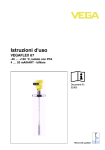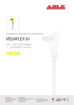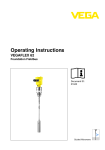
1
Operating Instructions
Electronics module
VEGAFLEX series 60
Contents
Contents
1
About this document
1.1
1.2
1.3
2
4.3
4.4
.
.
.
.
.
.
.
.
.
.
.
.
.
.
.
.
.
.
.
.
.
.
.
.
.
.
.
.
General instructions. . . . . . . . . . . . . . . . . . . . .
Mounting preparations VEGAFLEX 61, 62, 65,
66 . . . . . . . . . . . . . . . . . . . . . . . . . . . . . . . . .
Mounting preparations VEGAFLEX 67 . . . . . . .
Mounting procedure. . . . . . . . . . . . . . . . . . . . .
7
7
8
9
Setup . . . . . . . . . . . . . . . . . . . . . . . . . . . . . . . 11
Instrument repair . . . . . . . . . . . . . . . . . . . . . . . 13
Dismounting
7.1
7.2
8
6
6
6
.
.
.
.
Maintenance
6.1
7
Configuration. . . . . . . . . . . . . . . . . . . . . . . . . .
Principle of operation . . . . . . . . . . . . . . . . . . . .
Storage and transport . . . . . . . . . . . . . . . . . . .
.
.
.
.
Setup
5.1
6
5
5
5
5
.
.
.
.
Mounting
4.1
4.2
5
..
..
..
..
Authorised personnel . . . . . . . .
Appropriate use. . . . . . . . . . . .
Safety information for Ex areas.
Environmental instructions . . . .
Product description
3.1
3.2
3.3
4
4
4
4
For your safety
2.1
2.2
2.3
2.4
3
Function . . . . . . . . . . . . . . . . . . . . . . . . . . . . .
Target group . . . . . . . . . . . . . . . . . . . . . . . . . .
Symbolism used . . . . . . . . . . . . . . . . . . . . . . .
Dismounting procedure . . . . . . . . . . . . . . . . . . 14
Disposal . . . . . . . . . . . . . . . . . . . . . . . . . . . . . 14
Supplement
8.1
Technical data. . . . . . . . . . . . . . . . . . . . . . . . . 15
30207-EN-050607
2
Electronics module - VEGAFLEX series 60
About this document
1 About this document
1.1 Function
This operating instructions manual has all the information you
need for quick mounting and setup of a replacement
component. Please read this manual before you start setup.
1.2 Target group
This operating instructions manual is directed to trained
personnel. The contents of this manual should be made
available to these personnel and put into practice by them.
1.3 Symbolism used
Information, tip, note
This symbol indicates helpful additional information.
Caution, warning, danger
This symbol informs you of a dangerous situation that could
occur. Ignoring this cautionary note can impair the person and/
or the instrument.
Ex applications
This symbol indicates special instructions for Ex applications.
List
The dot set in front indicates a list with no implied sequence.
à
Action
This arrow indicates a single action.
1
Sequence
Numbers set in front indicate successive steps in a procedure.
30207-EN-050607
l
Electronics module - VEGAFLEX series 60
3
For your safety
2 For your safety
2.1 Authorised personnel
All operations described in this operating instructions manual
must be carried out only by trained specialist personnel
authorised by the operator. For safety and warranty reasons,
any internal work on the instruments must be carried out only
by personnel authorised by the manufacturer.
2.2 Appropriate use
Oscillator, emitting electronics, housing or process components are replacement components for existing sensors.
2.3 Safety information for Ex areas
Please note the Ex-specific safety information for installation
and operation in Ex areas. These safety instructions are part of
the operating instructions manual and come with the Exapproved instruments.
2.4 Environmental instructions
Protection of the environment is one of our most important
duties. That is why we have introduced an environment
management system with the goal of continuously improving
company environmental protection. The environment management system is certified acc. to DIN EN ISO 14001.
Please help us fulfil this obligation by observing the environmental instructions in this manual:
l
l
Chapter "Storage and transport"
Chapter "Disposal"
30207-EN-050607
4
Electronics module - VEGAFLEX series 60
Product description
3 Product description
3.1 Configuration
Scope of delivery
The scope of delivery encompasses:
l
l
Electronics module VEGAFLEX series 60
Documentation
- this operating instructions manual
3.2 Principle of operation
Area of application
The electronics module VEGAFLEX series 60 is suitable for
exchange with sensors acc. to the guided microwave principle
VEGAFLEX series 60.
3.3 Storage and transport
Packaging
Your instrument was protected by packaging during transport.
Its capacity to handle normal loads during transport is assured
by a test acc. to DIN EN 24180.
The packaging of standard instruments consists of environment-friendly, recyclable cardboard. For special versions PE
foam or PE foil is also used. Dispose of the packaging material
via specialised recycling companies.
Storage and transport temperature
l
30207-EN-050607
l
Storage and transport temperature see "Supplement –
Technical data – Ambient conditions"
Relative humidity 20 … 85 %
Electronics module - VEGAFLEX series 60
5
Mounting
4 Mounting
4.1 General instructions
If the electronics module is defective, it can be replaced by the
user.
In Ex applications, only one instrument and one oscillator with
appropriate Ex approval must be used.
If there is no electronics module available on site, it can be
ordered from the responsible VEGA agency.
Sensor serial number
The order data and company data of the sensor must be
loaded in the new oscillator. These are the options:
l
l
at the factory by VEGA personnel
or on site by the user.
Information:
When loading on site, first of all the order data must be
downloaded from the Internet (see "Setup").
In both cases, the sensor serial number is necessary. The
serial numbers are stated on the type label of the instrument,
inside the housing or on the delivery note.
Caution:
The order data and company data contain important presettings for the sensor. A reliable operation and a correction of the
measurement is not possible without these data.
Assignment
Electronics modules are adapted to the respective sensor.
They differ, e.g. in the signal output, the power supply or
approval.
First of all check by means of the overview in section Mounting
preparations, if you are using the suitable electronics module.
Compare the new electronics module with the existing one.
The specifications on the type label must correspond. This
applies mainly to instruments with approvals.
4 … 20 mA/HART
6
Electronics module FX-E.60H. suitable for VEGAFLEX 61, 62,
65, 66 – 4 … 20mA/HART:
Electronics module - VEGAFLEX series 60
30207-EN-050607
4.2 Mounting preparations VEGAFLEX 61, 62, 65,
66
Mounting
l
l
l
4 … 20 mA/HART four-wire
Electronics module FX-E.60V. suitable for VEGAPULS 61, 62,
63, 65, 66 – 4 … 20 mA/HART four-wire:
l
l
l
Profibus PA
FX-E.60VX (X = without approvals)
FX-E.60VA (A = approval DA 4 … 20 mA/HART-Vierleiter)
FX-E.60VC (C = approvals DX, EX , GX acc. to VEGA
product list).
Electronics module FX-E.60P. suitable for VEGAFLEX 61, 62,
63, 65, 66 – Profibus PA:
l
l
l
Foundation Fieldbus
FX-E.60HX (X = without approvals)
FX-E.60HA (A = approvals CA, DA acc. to VEGA product
list)
FX-E.60HC (C = approvals XM, CX, CM, CK, CI, DX, DM,
DI, GX, UX, UF acc. to VEGA product list).
FX-E.60PX (X = without approvals)
FX-E.60PA (A = approvals CA, DA acc. to VEGA product
list)
FX-E.60PC (C = approvals XM, CX, CM, CK, GX acc. to
VEGA product list).
Electronics module FX-E.60F. suitable for VEGAFLEX 61, 62,
63, 65, 66 – Foundation Fieldbus FF:
l
l
FX-E.60FX (X = without approvals)
FX-E.60KFC (C = approvals CX CK, GX acc. to VEGA
product list).
4.3 Mounting preparations VEGAFLEX 67
4 … 20 mA/HART
Electronics module FX-E.67H. suitable for VEGAFLEX 67 –
4 … 20 mA/HART:
l
l
Profibus PA
Electronics module FX-E.67P. suitable for VEGAFLEX 67 –
Profibus PA:
l
30207-EN-050607
l
Foundation Fieldbus
FX-E.67HX (X = without approvals)
FX-E.67HC (C = approvals XM, CX, CM, CK, CI, DX, DM,
DI acc. to VEGA product list).
FX-E.67PX (X = without approvals)
FX-E.67PC (C = approvals XM, CX, CM acc. to VEGA
product list).
Electronics module FX-E.67F. suitable for VEGAFLEX 67 –
Foundation Fieldbus FF:
l
l
FX-E.67FX X = without approvals)
FX-E.67CFC (C = approval CX acc. to VEGA product list).
Electronics module - VEGAFLEX series 60
7
Mounting
4.4 Mounting procedure
Mounting procedure
The electronics module is located in the electronics compartment. The below illustrations show the respective position of
the electronics compartment in a single or double chamber
housing.
1
Fig. 1: Single chamber housing
1 Position of the electronics module
1
Fig. 2: Double chamber housing
1 Position of the electronics module
Proceed as follows:
1
Switch off power supply
2
Unscrew housing cover of the electronics compartment
3
Disconnect the connection cables acc. to the operating
instructions manual of the respective sensor
4
Loosen the two screws with a Phillips screwdriver (size 1)
30207-EN-050607
8
Electronics module - VEGAFLEX series 60
Mounting
1
2
Fig. 3: Loosen the screws
1 Electronics module
2 Screws (2 pcs.)
5
Pull the previous electronics out by holding the opening
levers.
6
Insert the new oscillator carefully.
7
Screw in and tighten the two screws with a Phillips
screwdriver.
8
Connect the connection cables acc. to the operating
instructions manual of the respective sensor
9
Screw the housing cover back on
The electronics exchange is finished.
30207-EN-050607
As a rule, the exchange of the electronics must be
documented internally when used in Ex applications.
Electronics module - VEGAFLEX series 60
9
Setup
5 Setup
5.1 Setup
With sensor serial number
If you have ordered the electronics module by stating the
sensor serial number, it is ready for operation after
installation and connection to power supply.
Without sensor serial number
If you have ordered the electronics module without stating
the sensor serial number or you are using a suitable
electronics module from stock, you first have to load the
sensor data after installation.
Load sensor data
Move via www.vega.com to the item "serial number search".
The order data of the sensor will be displayed after entering
the serial number.
Fig. 4: Example for the order data of a sensor.
10
Electronics module - VEGAFLEX series 60
30207-EN-050607
Below the order data you will find as an XML file "Sensor data
for Service-DTM". Load these data with "Save target as" to
your PC and finally export them via PACTware™ and the
Service DTM to the sensor.
Setup
Adjustment
As a rule, settings already carried out on site with the previous
electronics module such as min./max. adjustment, gating out
of false echoes etc., however must be repeated.
30207-EN-050607
Tip:
Simply use the copy function of the adjustment module
PLICSCOM or the adjustment software PACTware™.
Electronics module - VEGAFLEX series 60
11
Maintenance
6 Maintenance
6.1 Instrument repair
If it is necessary to repair the replacement component, please
proceed as follows:
You can download a return form (23 KB) from our homepage
www.vega.com under: "Services – Downloads – Forms and
Certificates – Repair form".
By doing this you help us carry out the repair quickly and
without having to call back for needed information.
l
l
l
l
Print and fill out one form per instrument
Clean the instrument and pack it damage-proof
Attach the completed form and possibly also a safety data
sheet to the instrument.
Send the instrument to the respective address of your
agency. In Germany to the VEGA headquarters in
Schiltach.
30207-EN-050607
12
Electronics module - VEGAFLEX series 60
Dismounting
7 Dismounting
7.1 Dismounting procedure
Take note of chapters "Mounting" and "Connecting to power
supply" and carry out the listed steps in reverse order.
7.2 Disposal
The replacement component consists of materials which can
be recycled by specialised recycling companies. We have
purposely designed the electronic modules to be easily
separable. Mark the instrument as scrap and dispose of it
according to government regulations (electronic scrap ordinance, ...)
Materials: see "Technical data"
30207-EN-050607
If you cannot dispose of the instrument properly, please
contact us about disposal methods or return.
Electronics module - VEGAFLEX series 60
13
Supplement
8 Supplement
8.1 Technical data
Technical data
are stated in the operating instructions manual of the appropriate sensor.
30207-EN-050607
14
Electronics module - VEGAFLEX series 60
30207-EN-050607
Electronics module - VEGAFLEX series 60
15
VEGA Grieshaber KG
Am Hohenstein 113
77761 Schiltach
Germany
Phone +49 7836 50-0
Fax +49 7836 50-201
E-mail: [email protected]
www.vega.com
ISO 9001
All statements concerning scope of delivery, application,
practical use and operating conditions of the sensors and
processing systems correspond to the information available at the time of printing.
Technical data subject to alterations
30207-EN-050607