1
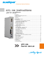
Professional Headend Solutions Professional Headend Solutions Operating instructions ATC-199 Operating instructions ASI Transmodulator TWIN TWIN ASI Transmodulator ASI-TS CI (AM) → ATV (AM) ASI-TS → CI →→ ATV Contents Contents 1. Safety and operating instructions ................................................................... 2 1. Safety and operating instructions ................................................................... 2 Device variants .............................................................................................. 2 2. Device2. variants .............................................................................................. 2 General ................. ........................................................................................... 2 3. General3.................. ........................................................................................... 2 4. Front view........................................................................................... ............. ........................................................................................... 3 4. Front view ............. 3 5. Functional description ...................................................................................... 3 5. Functional description ...................................................................................... 3 6. Adjustments ....... ............................................................................................. 3 6. Adjustments ....... ............................................................................................. 3 6.1 Adjustment with the Headend .................................................. 3 6.1 Adjustment with the Headend ControllerController .................................................. 3 6.2 Adjustment withlaptop the PC/ laptop ................................................................. 4 6.2 Adjustment with the PC/ ................................................................. 4 6.3 Adjustment with SNMP .............................................................................. 4 6.3 Adjustment with SNMP .............................................................................. 4 7. of Meaning of the LED`s ..................................................................................... 4 7. Meaning the LED`s ..................................................................................... 4 the ASI ports .............................................................................. 4 7.1 LED`s7.1 at LED`s the ASIatports .............................................................................. 4 Status........................................................................................... LED`s ........................................................................................... 4 7.2 Status7.2 LED`s 4 8. Programming by web server ...........................................................................5 8. Programming by web server ...........................................................................5 8.1 Main.............................................................................................. menu .............................................................................................. 5 8.1 Main menu 5 8.2 Configuration of ASI2channel 2 ................................................................. 6 8.2 Configuration of ASI channel ................................................................. 6 8.3 Configuration 1 ...... .................................................................. 6 8.3 Configuration of TS-PLLof1 TS-PLL ...... .................................................................. 6 8.4the Loading the programme list ...................................................................... 6 8.4 Loading programme list ...................................................................... 6 8.5 CA ..... ............................................................................................. 6 8.5 CA menu .....menu ............................................................................................. 6 8.6settings Factory........................................................................................ settings ........................................................................................ 7 8.6 Factory 7 8.7 options Software.......................................................................................7 options .......................................................................................7 8.7 Software 8.8 Extended settings ..................................................................................... 8 8.8 Extended settings ..................................................................................... 8 8.9settings Manual ........................................................................................ settings ........................................................................................ 9 8.9 Manual 9 8.10 of the device ................................................................................. 9 8.10 Status of Status the device ................................................................................. 9 Manual menu at the Headend ......................................... 10 9. Manual9.menu control atcontrol the Headend ControllerController ......................................... 10 10. Trap messages ... ......................................................................................... 11 10. Trap messages ... ......................................................................................... 11 Block diagram ............................................................................................ 11 11. Block 11. diagram ............................................................................................ 11 end bus ............................................................................... structure ............................................................................... 11 12. Head 12. endHead bus structure 11 13. Application example ..................................................................................... 12 13. Application example ..................................................................................... 12 14. Technical data .. ........................................................................................... 12 14. Technical data .. ........................................................................................... 12 15. Glossary .............................. ........................................................................ 13 15. Glossary .............................. ........................................................................ 13 16. Bibliography .... ........................................................................................... 13 16. Bibliography .... ........................................................................................... 13 17. Document history ................ ........................................................................ 13 17. Document history ................ ........................................................................ 13 ATCATC 199 199 No: 9613.01 PartPart No: 9613.01 ATC 199 Part N : 9613.01 TWIN ASI Transmodulator ASI-TS → CI → ATV (AM) o + C LINE 4. Front view LINE+ C managed by SNMP ASI-TS input port 1 LED input 1 ASI-TS input port 2/ output port LED input 2/ output ASI IN TWIN ASI TRANSMODULATOR ASI-TS CI ATV (AM) Type: ATC 199 Part No.: 9613.01 ASI/TS-MODE burst,continuous 188, 204 ASI/TS-RATE 270/0.625..78 Mbps INPUT LEVEL 200...880 mVpp TV-RF OUT 45...862 MHz OUTPUT LEVEL max. 94 dBµV TV-STANDARD B/G, D/K, I, L, M SUPPLY CURRENT 0.7 A ASI IN/OUT TWIN ASI TRANSMODULATOR ASI-TS CI ATV (AM) Type: ATC 199 Part No.:9613.01 ASI/TS-MODE burst,continuous/ 188,204 ASI/TS-Rate 270/0.625...78 Mbps INPUT LEVEL 200...880 mVpp TV - RF OUT 45 … 862 MHz OUTPUT LEVEL max. 94 dBµV TV-STANDARD B/G, D/K, I, L, M SUPPLY CURRENT 0.7 A X2 X1 STANDBY READY 1 READY 2 ADDR. IN OUTPUT LOOP TV - RF OUT gile Operating voltage/ control bus CI slot 1 CI slot 2 LED „STANDBY“ (red) LED „READY 1“ (green) LED „READY 2“ (green) LED „ADDR.“ (yellow) Address selector Output coupler “input“ Output coupler “output“ 5. Functional description With this transmodulator, the digital ASI signal is decoded and then transferred into a serial data stream. Next, that data stream is parallelised and fed into a FIFO system. The timing of this data input will in all cases be adapted to the general data input rate. The regeneration system for the transport stream SPI protocol follows at the FIFO system output, and at the same time, recognition of the transport stream being correct is ensured. It is at this level that the transport stream can be edited. The transport stream will be fed directly to the DVB module or via the Common Interface.* The DVB module consists of the demultiplexer and the MPEG decoder. The DVB module generates an analogue video- and audio signal. The ATC 199 supports services like Teletext, VPS, WSS, optional test lines, the flash of subtitles, the insertion of black bars and BISS decryption. The BISS mode 1 and the BISS mode E with input of the necessary Injected ID are supported, but not the BISS mode E with the additional input of the optional Buried ID. Using the black-bar-option it can be selected, where the black bar will be inserted (left, right, above or below the image). The width of the bar can be selected in % related to standard 4:3 format. Different values for 16:9- and special 16:9 format can be adjusted. The activation of the black bar is only possible when adjusted colour system is PAL and the video format is letterbox. A timer-controlled activation of this option is supported by HCB 100 (9650.04/.05) or HCB 200/ 300 with software version 3.26 or higher. The analogue signals feed the IF modulators. After IF filtering follows the conversion into the wanted output channels. Two independent adjustable channels (output frequency and level) are available at the output. The second ASI port can be adjusted as input or loop trough output by software. Outputs are performed in loop through technology therefore distribution and combining are realized within the module. * The design of the Common interface of this module is done according to DVB standards. Because of the dependencies in interaction of the DVB signals, CA modules and smart cards we can not assure a general functional capability for all application possibilities. Please contact our service department for further assistance. 6. Adjustments 6.1 Adjustment with the Headend Controller · Adjustment of the addresses at the Bus Extender BEB x00 and at the modules · Activation of the programming mode on each module by selecting the line (BEB x00) and the module position (01... 15) at the Headend Controller (HCB x00) → yellow LED illuminates until the beginning of the parameter adjustment · Adjustment of the ATC 199 parameters (see chapter 9) → green LED is switched on · After the programming the ATC 199 will be automatically switched into the operating mode → yellow LED flashes shortly/ green LED is switched on The manual instructions of the Headend Controller HCB x00 and the Bus Extender BEB x00 have to be considered! 3 ATC 199 Part N : 9613.01 o TWIN ASI Transmodulator ASI-TS → CI → ATV (AM) + C LINE 8. Programming by web server* 8.1 Main menu name of device, item number, address in head end ASI-Channel Status ASI-Channel 2 TS-PLL Channel Description Input ASI source displays the respective ASI channel (1/ 2) If channel is an input (channel 1 always, channel 2 after configuration), there is displays whether SYNChronization or noSYNChronization with input. If channel 2 is configured as output, there is displayed: “configured as output“ configuration button of ASI channel 2 (see menu 1) configuration button to enable or disable of the TS-PLL 1 (see menu 2) displays the respective modulator channel name of programme (max. 30 characters) displays which ASI channel is used as source of the TS. If ASI port 2 is configured as input, it will be the source of the modulator channel automatically. Otherwise the ASI port 1 is the TS source of both modulator channels. BISS-Settings (will only be available if “BISS decryption” option is on) BISS-Key BISS-E injected ID Program settings Program listing Service-ID Audio language Language code Service type Audio settings Mode Audio gain Common Interface Status CA-Menu Channel 1+2 Operating status SNMP-Trap mess. MPEG SYNC check Factory settings input of the 12-digit code in BISS mode 1 or of the 16-digit code in BISS mode E input of the 14-digit code in BISS mode E, no input in BISS mode 1! see menu 3 adjustment range: 0...65535 adjustment range: 0...255 displays the code for the language selected displays the type of service selected (TV, radio) selection: monoL+R, monoL, monoR, dual, dual invers, stereo, auto adjustment range: +6...-20 dB displays the type of the CA module per slot see menu 4 selection: On, Off, Reset On/ Off, if SNMP option in HCB x00 enabled, otherwise “locked“ displays selection: fast, normally, slowly see menu 5 Routing to the appropriate adjustment menu: Extended settings see menu 7 Software option see menu 6 Status see menu 9 * For further details see the HCB manual 5 ATC 199 Part N : 9613.01 o TWIN ASI Transmodulator ASI-TS → CI → ATV (AM) 8.2 Configuration of ASI channel 2 (menu 1) + C LINE name of device, item number, address in head end In this menu, the ASI channel 2 can be separately configured as an input or as an output to loop throught the ASI input stream. 8.3 Configuration of TS-PLL 1 (menu 2) name of device, item number, address in head end Sources with normal distributed PCR jitter may be improved by this option. For those reasons the ASI front end channel 1 contains a TS stabilization based on a PLL. This functionality can be enabled or disabled in this menu (default: off). Multiplexers and IP gateways used for feeding adjust the PCR themselves, therefore the PLL should remain deactivated in those cases. 8.4 Loading the programme list (menu 3) This menu contains a list of all services contained in the data stream. Language selection can take place here if available. Any service is adopted or given new settings by clicking the relevant “Set” button. 8.5 CA menu (menu 4) name of device, item number, address in head end On these pages all menus implemented in the CA module are offered.The available menus are selected individually or are invoked one-by-one to do necessary settings or to get all informations about the CA module. 6 ATC 199 Part N : 9613.01 TWIN ASI Transmodulator ASI-TS → CI → ATV (AM) o + C 10. Trap messages Item. Message Message type Explanation 01 Signal OK INFORMATION input synchronized 02 Input not sync WARNING input not synchronized 03 MPEG error CRITICAL MPEG error 04 IIC Error CRITICAL IIC bus or hardware error 05 System reset WARNING reset by internal error 06 MPEG-Decoder not sync WARNING MPEG decoder not synchronized 07 Power fail CRITICAL power supply error 08 Audio mode=mono INFORMATION Audio mode is set as mono 09 Audio mode=summ mono INFORMATION Audio mode is set as mono total 10 Audio mode=mono1 INFORMATION Audio mode is set as mono 1 11 Audio mode=mono2 INFORMATION Audio mode is set as mono 2 12 Audio mode=stereo INFORMATION Audio mode is set as stereo 13 Audio mode=dual INFORMATION Audio mode is set as dual LINE 11. Block diagram CAM MPEG decoder BISS descrambler CI ASI Video-/ audioprocessing Vestigial sideband IF modul. Video-/ audioprocessing Vestigial sideband IF modul. IF 2x FM modulator RF ASI front end MPEG decoder CI BISS descrambler 2x FM modulator CAM Module ADDR. 15 Module ADDR. 01 BEB x00 ADDR. 01 Module ADDR. 01 Module ADDR. 15 Module ADDR. 01 Module ADDR. 15 Module signal processing unit BEB x00 ADDR. 02 BEB x00 Bus Extender BEB x00 ADDR. 15 . HCB x00 Headend Controller HCB x00 12. Head end bus structure The number of the possible module connections (00 ... 15) to a BEB x00 depends on the total power consumption of this line! 11 RF 45...862 MHz IF RF ATC 199 Part N : 9613.01 TWIN ASI Transmodulator ASI-TS → CI → ATV (AM) o + C 13. Application example LINE Integration in existing C-LINE configuration Conversion of different programs of different multi program transport streams into PAL Feed from IP backbone HCB 200 Control ASI ASI ASI ASI ASI ASI ASI ASI ASI ASI ASI ASI ASI Stream ASI ASI 1 2 3 4 5 6 ATC 199 ATC 199 ATC 199 ATC 199 ATC 199 ATC 199 ATC 199 ITB 100 Output to existing combining 14 x PAL level opt. 86 dBµV 14. Technical data ASI input Level range Data rate Connector Impedance ASI polarity ASI output Level Data rate Connector Impedance ASI polarity ASI signal processing Data rate ASI transfer format Input Output TS transfer format Input Output Signal processing Decryption interface Common Interface 200 … 880 mVpp 270 Mbps BNC socket 75 Ω regular/ inverted 800 mVpp (± 10 %) 270 Mbps BNC socket 75 Ω normal 0.625…78 Mbps continuous, burst burst 188, 204 Byte 188, 204 Byte EN 50083-9 [3] Operating voltage per channel PCMCIA-slot according to EN 50221 [4] 5V TV output TV standards Sound procedure (B/G, D/K) Sound (B/G, D/K) Sound (I, L, M) Max. output level Level adjustment range Impedance Connector Through loss Output frequency range Tuning step B/G, D/K, I, L, M FM dual carrier mono/ stereo/ dual/ auto mono 94 dBµV 20 dB (0.5 dB steps) 75 Ω F socket ≤ 1.5 dB 45 … 862 MHz 125 kHz Operating parameters Voltage/ current Residual ripple of the supply voltage Environmental conditions Temperature range Temperature range for data keeping Relative humidity Method of mounting Location of mounting Miscellaneous Dimensions (l x w x h) without 19”-adapter with 19”-adapter Weight 12 V (± 0.2 V) / 700 mA (without CA module) ≤ 10 mVpp -10 ... +55 °C 5 ... 45 °C ≤ 80 % (non condensing) vertical splash-proof and drip-proof 50 x 276 x 148 mm 50 x 301 x 148 mm 1,130 g Delivery content 1 x bus connector 1 x F connecting cable 140 mm Software options Test lines Subtitling BISS decryption Insertion of black bars 12 CKB 101 CKB 102 CKB 104 CKB 106 9650.51 9650.52 9650.54 9650.56 Declaration of Conformity The Manufacturer BLANKOM Antennentechnik GmbH ∙ Hermann-Petersilge-Str. 1 ∙ 07422 Bad Blankenburg ∙ Germany herewith declares the conformity of the product Product name: TWIN ASI Transmodulator Type: ATC 199 Product number: 9613.01 according to the following regulations EN 50083-2 EN 60728-11 (as far as relevant) and additional device-specific regulations, enclosed above, which this product is subjected to. Date: 23.06.2010 Signature: (Managing Director) 14