1
Operating Instructions
TDR sensor for continuous level and
interface measurement of liquids
VEGAFLEX 83
Foundation Fieldbus
Polished rod probe
Document ID: 44224
Contents
Contents
About this document
1.1 Function ........................................................................................................................... 4
1.2 Target group ..................................................................................................................... 4
1.3 Symbols used................................................................................................................... 4
2
For your safety
2.1 Authorised personnel ....................................................................................................... 5
2.2 Appropriate use ................................................................................................................ 5
2.3 Warning about incorrect use............................................................................................. 5
2.4 General safety instructions ............................................................................................... 5
2.5 CE conformity................................................................................................................... 5
2.6 NAMUR recommendations .............................................................................................. 6
2.7 Environmental instructions ............................................................................................... 6
3
Product description
3.1 Configuration .................................................................................................................... 7
3.2 Principle of operation........................................................................................................ 8
3.3 Packaging, transport and storage ................................................................................... 11
3.4 Accessories and replacement parts ............................................................................... 11
4
Mounting
4.1 General instructions ....................................................................................................... 14
4.2 Mounting instructions ..................................................................................................... 14
5
Connecting to power supply
5.1 Preparing the connection ............................................................................................... 20
5.2 Connecting ..................................................................................................................... 20
5.3 Wiring plan, single chamber housing.............................................................................. 22
5.4 Wiring plan, double chamber housing ............................................................................ 22
5.5 Double chamber housing with DIS-ADAPT .................................................................... 24
5.6 Wiring plan - version IP 66/IP 68, 1 bar........................................................................... 25
5.7 Supplementary electronics ............................................................................................. 25
5.8 Switch-on phase............................................................................................................. 25
6
Set up with the display and adjustment module
6.1 Insert display and adjustment module ............................................................................ 27
6.2 Adjustment system ......................................................................................................... 28
6.3 Parameter adjustment - Quick setup .............................................................................. 29
6.4 Parameter adjustment - Extended adjustment................................................................ 32
6.5 Saving the parameter adjustment data ........................................................................... 47
7
Setup with PACTware
7.1 Connect the PC .............................................................................................................. 48
7.2 Parameter adjustment with PACTware ............................................................................ 48
7.3 Set up with the quick setup............................................................................................. 49
7.4 Saving the parameter adjustment data ........................................................................... 54
8
Set up with other systems
8.1 DD adjustment programs ............................................................................................... 55
8.2 Field Communicator 375, 475 ........................................................................................ 55
9
Diagnostics and service
9.1 Maintenance .................................................................................................................. 56
2
VEGAFLEX 83 • Foundation Fieldbus
44224-EN-140430
1
Contents
9.2
9.3
9.4
9.5
9.6
9.7
9.8
Diagnosis memory ......................................................................................................... 56
Status messages............................................................................................................ 57
Rectify faults ................................................................................................................... 61
Exchanging the electronics module ................................................................................ 65
Exchanging the rod ........................................................................................................ 66
Software update ............................................................................................................. 67
How to proceed if a repair is needed .............................................................................. 68
10 Dismounting
10.1 Dismounting steps.......................................................................................................... 69
10.2 Disposal ......................................................................................................................... 69
44224-EN-140430
11 Supplement
11.1 Technical data ................................................................................................................ 70
11.2 Supplementary information Foundation Fieldbus ........................................................... 77
11.3 Dimensions .................................................................................................................... 88
Safety instructions for Ex areas
PleasenotetheEx-specificsafetyinformationforinstallationandoperation in Ex areas. These safety instructions are part of the operating
instructions manual and come with the Ex-approved instruments.
Editing status: 2014-03-31
VEGAFLEX 83 • Foundation Fieldbus
3
1 About this document
1
About this document
1.1
Function
1.2
Target group
1.3
Symbols used
This operating instructions manual provides all the information you
need for mounting, connection and setup as well as important instructionsformaintenanceandfaultrectification.Pleasereadthisinformation before putting the instrument into operation and keep this manual
accessible in the immediate vicinity of the device.
This operating instructions manual is directed to trained specialist
personnel. The contents of this manual should be made available to
these personnel and put into practice by them.
Information, tip, note
This symbol indicates helpful additional information.
Caution: If this warning is ignored, faults or malfunctions can result.
Warning: If this warning is ignored, injury to persons and/or serious
damage to the instrument can result.
Danger: If this warning is ignored, serious injury to persons and/or
destruction of the instrument can result.
•
→
1
Ex applications
This symbol indicates special instructions for Ex applications.
List
The dot set in front indicates a list with no implied sequence.
Action
This arrow indicates a single action.
Sequence of actions
Numbers set in front indicate successive steps in a procedure.
Battery disposal
This symbol indicates special information about the disposal of batteries and accumulators.
44224-EN-140430
4
VEGAFLEX 83 • Foundation Fieldbus
2 For your safety
2
2.1
For your safety
Authorised personnel
All operations described in this operating instructions manual must
be carried out only by trained specialist personnel authorised by the
plant operator.
During work on and with the device the required personal protective
equipment must always be worn.
2.2
Appropriate use
VEGAFLEX 83 is a sensor for continuous level measurement.
Youcanfinddetailedinformationabouttheareaofapplicationin
chapter "Product description".
Operational reliability is ensured only if the instrument is properly
usedaccordingtothespecificationsintheoperatinginstructions
manual as well as possible supplementary instructions.
2.3
Warning about incorrect use
2.4
General safety instructions
Inappropriate or incorrect use of the instrument can give rise to
application-specifichazards,e.g.vesseloverfillordamagetosystem
components through incorrect mounting or adjustment.
This is a state-of-the-art instrument complying with all prevailing
regulations and guidelines. The instrument must only be operated in a
technicallyflawlessandreliablecondition.Theoperatorisresponsible
for the trouble-free operation of the instrument.
During the entire duration of use, the user is obliged to determine the
compliance of the necessary occupational safety measures with the
current valid rules and regulations and also take note of new regulations.
The safety instructions in this operating instructions manual, the national installation standards as well as the valid safety regulations and
accident prevention rules must be observed by the user.
For safety and warranty reasons, any invasive work on the device
beyond that described in the operating instructions manual may be
carried out only by personnel authorised by the manufacturer. Arbitraryconversionsormodificationsareexplicitlyforbidden.
44224-EN-140430
The safety approval markings and safety tips on the device must also
be observed.
2.5
CE conformity
ThedevicefulfillsthelegalrequirementsoftheapplicableECguidelines.ByaffixingtheCEmarking,weconfirmsuccessfultestingofthe
product.
YoucanfindtheCECertificateofConformityinthedownloadsection
of our homepage.
VEGAFLEX 83 • Foundation Fieldbus
5
2 For your safety
Electromagnetic compatibility
Instruments in four-wire or Ex-d-ia version are designed for use in an
industrial environment. Nevertheless, electromagnetic interference
from electrical conductors and radiated emissions must be taken into
account, as is usual with class A instruments according to EN 613261.Iftheinstrumentisusedinadifferentenvironment,theelectromagnetic compatibility to other instruments must be ensured by suitable
measures.
2.6
NAMUR recommendations
NAMUR is the automation technology user association in the process
industry in Germany. The published NAMUR recommendations are
acceptedasthestandardinfieldinstrumentation.
ThedevicefulfillstherequirementsofthefollowingNAMURrecommendations:
•
•
•
•
NE 21 – Electromagnetic compatibility of equipment
NE 43 – Signal level for malfunction information from measuring
transducers
NE53–Compatibilityoffielddevicesanddisplay/adjustment
components
NE107–Self-monitoringanddiagnosisoffielddevices
For further information see www.namur.de.
2.7
Environmental instructions
Protection of the environment is one of our most important duties.
That is why we have introduced an environment management system
with the goal of continuously improving company environmental protection.Theenvironmentmanagementsystemiscertifiedaccording
to DIN EN ISO 14001.
Pleasehelpusfulfillthisobligationbyobservingtheenvironmental
instructions in this manual:
•
•
Chapter "Packaging, transport and storage"
Chapter "Disposal"
44224-EN-140430
6
VEGAFLEX 83 • Foundation Fieldbus
3 Product description
3
Type label
Product description
3.1 Configuration
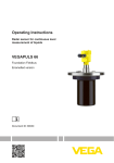
Thetypelabelcontainsthemostimportantdataforidentificationand
use of the instrument:
1
2
16
15
3
14
4
5
6
7
8
9
10
13
12
11
Fig. 1: Layout of the type label (example)
1 Instrument type
2 Product code
3 Approvals
4 Power supply and signal output, electronics
5 Protection rating
6 Probe length
7 Process and ambient temperature, process pressure
8 Material, wetted parts
9 Hardware and software version
10 Order number
11 Serial number of the instrument
12 Symbol of the device protection class
13 ID numbers, instrument documentation
14 Reminder to observe the instrument documentation
15 NotifiedauthorityforCEmarking
16 Approval directives
44224-EN-140430
Serial number - Instrument search
The type label contains the serial number of the instrument. With it
youcanfindthefollowinginstrumentdataonourhomepage:
•
•
•
•
•
•
Product code (HTML)
Delivery date (HTML)
Order-specificinstrumentfeatures(HTML)
Operating instructions and quick setup guide at the time of shipment (PDF)
Order-specificsensordataforanelectronicsexchange(XML)
Testcertificate(PDF)-optional
Go to www.vega.com, "VEGATools" and "Instrument search". Enter
the serial number.
Alternatively, you can access the data via your smartphone:
•
Download the smartphone app "VEGATools" from the "Apple App
Store" or the "GooglePlayStore"
VEGAFLEX 83 • Foundation Fieldbus
7
3 Product description
•
•
Scan the Data Matrix code on the type label of the instrument or
Enter the serial number manually in the app
Scope of this operating
instructions manual
This operating instructions manual applies to the following instrument
versions:
Versions
This electronics version can be determined via the product code on
the type label as well as on the electronics.
•
•
•
•
Hardware from 1.0.0
Software from 1.0.0
OnlyforinstrumentversionswithoutSILqualification
Standard electronics: Type FX80FF.-
Scope of delivery
The scope of delivery encompasses:
Application area
The VEGAFLEX 83 is a level sensor with polished rod probe for
continuous level or interface measurement, particularly suitable for
applications in the food processing and pharmaceutical industry.
•
•
Sensor
Documentation
– this operating instructions manual
– Testcertificatemeasuringaccuracy(optional)
– Operating instructions manual "Display and adjustment module" (optional)
– Supplementary instructions "GSM/GPRSradiomodule"
(optional)
– Supplementary instructions manual "Heating for display and
adjustment module" (optional)
– Supplementary instructions manual "Plug connector for continuously measuring sensors" (optional)
– Ex-specific"Safety instructions" (with Ex versions)
– ifnecessary,furthercertificates
3.2
Principle of operation
Optionally an autoclaved version with separable housing is available.
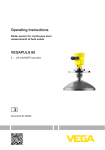
Functional principle level measurement
High frequency microwave pulses are guided along a steel cable or
a rod. Upon reaching the product surface, the microwave pulses are
reflected.Therunningtimeisevaluatedbytheinstrumentandoutputted as level.
44224-EN-140430
8
VEGAFLEX 83 • Foundation Fieldbus
3 Product description
1
d
h
Fig. 2: Level measurement
1 Sensorreferenceplane(sealsurfaceoftheprocessfitting)
d Distance to the interface
h Height - Level
Probe end tracking
To increase sensitivity, the probe is equipped with probe end tracking.
In products with a low dielectric constant, this function is very helpful.
This is the case, for example, in plastic granules, packing chips or in
vesselswithfluidizedproducts.
Between a dielectric constant of 1.5 and 3, the function switches on, if
required. As soon as the level echo can no longer be detected, probe
end tracking is automatically activated. The measurement is continued with the last calculated dielectric constant.
The accuracy thus depends on the stability of the dielectric constant.
If you measure a medium with a dielectric constant below 1.5, probe
end tracking is always active. In this case, you have to enter the
dielectric constant of the medium. A stable dielectric constant is very
important here.
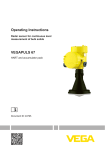
High frequency microwave impulses are guided along a steel cable or
rod. Upon reaching the product surface, a part of the microwave impulsesisreflected.Theotherpartpassesthroughtheupperproduct
andisreflectedbytheinterface.Therunningtimestothetwoproduct
layers are processed by the instrument.
44224-EN-140430
Functional principle - interface measurement
VEGAFLEX 83 • Foundation Fieldbus
9
3 Product description
h2
h1
L3
d2
L2
TS
1
d1
L1
Fig. 3: Interface measurement
1 Sensorreferenceplane(sealsurfaceoftheprocessfitting)
d1 Distance to the interface
d2 Distance to the level
TS Thicknessoftheuppermedium(d1-d2)
h1 Height - Interface
h2 Height - Level
L1 Lower medium
L2 Upper medium
L3 Gasphase
Prerequisites for interface measurement
Upper medium (L2)
• The upper medium must not be conductive
• The dielectric constant of the upper medium or the actual distance
to the interface must be known (input required). Min. dielectric constant:1.6.Youcanfindalistofdielectricconstantsonourhome
page: www.vega.com.
• The composition of the upper medium must be stable, no varying
products or mixtures
• Theuppermediummustbehomogeneous,nostratifications
within the medium
• Min. thickness of the upper medium 50 mm (1.97 in)
• Clear separation from the lower medium, emulsion phase or detritus layer max. 50 mm (1.97 in)
• If possible, no foam on the surface
Lower medium (L1)
The dielectric constant must be 10 higher than the dielectric
constant of the upper medium, preferably electrically conductive.
Example: upper medium dielectric constant 2, lower medium at
least dielectric constant 12.
•
10
VEGAFLEX 83 • Foundation Fieldbus
44224-EN-140430
Gas phase (L3)
Air or gas mixture
Gas phase - dependent on the application, gas pahse does not
always exist (d2 = 0)
•
•
3 Product description
Output signal
The instrument is always preset to the application "Level measurement".
For the interface measurement, you can select the requested output
signal with the setup.
Packaging
3.3
Packaging, transport and storage
Your instrument was protected by packaging during transport. Its
capacity to handle normal loads during transport is assured by a test
based on ISO 4180.
The packaging of standard instruments consists of environmentfriendly, recyclable cardboard. For special versions, PE foam or PE
foil is also used. Dispose of the packaging material via specialised
recycling companies.
Transport
Transport must be carried out in due consideration of the notes on the
transport packaging. Nonobservance of these instructions can cause
damage to the device.
Transport inspection
The delivery must be checked for completeness and possible transit
damage immediately at receipt. Ascertained transit damage or concealed defects must be appropriately dealt with.
Storage
Up to the time of installation, the packages must be left closed and
stored according to the orientation and storage markings on the
outside.
Unless otherwise indicated, the packages must be stored only under
the following conditions:
Storage and transport
temperature
PLICSCOM
•
•
•
•
•
•
•
Not in the open
Dry and dust free
Not exposed to corrosive media
Protected against solar radiation
Avoiding mechanical shock and vibration
Storage and transport temperature see chapter "Supplement Technicaldata-Ambientconditions"
Relative humidity 20 … 85 %
3.4
Accessories and replacement parts
The display and adjustment module PLICSCOM is used for measured
value indication, adjustment and diagnosis. It can be inserted into the
sensor or the external display and adjustment unit and removed at
any time.
44224-EN-140430
Youcanfindfurtherinformationintheoperatinginstructions"Display
andadjustmentmodulePLICSCOM" (Document-ID 27835).
VEGACONNECT
The interface adapter VEGACONNECT enables the connection of
communication-capable instruments to the USB interface of a PC. For
parameter adjustment of these instruments, the adjustment software
PACTware with VEGA-DTM is required.
VEGAFLEX 83 • Foundation Fieldbus
11
3 Product description
Youcanfindfurtherinformationintheoperatinginstructions"Interface
adapterVEGACONNECT" (Document-ID 32628).
VEGADIS 81
The VEGADIS 81 is an external display and adjustment unit for VEGA
plics® sensors.
For sensors with double chamber housing the interface adapter "DISADAPT" is also required for VEGADIS 81.
Youcanfindfurtherinformationintheoperatinginstructions"VEGADIS81" (Document-ID 43814).
DIS-ADAPT
The adapter "DIS-ADAPT" is an accessory part for sensors with
double chamber housings. It enables the connection of VEGADIS 81
to the sensor housing via an M12 x 1 plug.
Youcanfindfurtherinformationinthesupplementaryinstructions
"AdapterDISADAPT" (Document-ID 45250).
PLICSMOBILE T61
The PLICSMOBILE T61 is an external GSM/GPRS radio unit for
transmission of measured values and for remote parameter adjustment of plics® sensors. The adjustment is carried out via PACTware/
DTM by using the integrated USB connection.
Youcanfindfurtherinformationinthesupplementaryinstructions
"PLICSMOBILET61" (Document-ID 37700).
Protective cap
The protective cover protects the sensor housing against soiling and
intense heat from solar radiation.
Youwillfindadditionalinformationinthesupplementaryinstructions
manual "Protective cover" (Document-ID 34296).
Flanges
Screwedflangesareavailableindifferentversionsaccordingtothe
following standards: DIN 2501, EN 1092-1, BS 10, ANSI B 16.5,
JIS B 2210-1984, GOST 12821-80.
Youcanfindadditionalinformationinthesupplementaryinstructions
manual "FlangesaccordingtoDIN-EN-ASME-JIS" (Document-ID
31088).
Electronics module
The electronics module VEGAFLEX series 80 is a replacement part
forTDRsensorsofVEGAFLEXseries80.Thereisadifferentversion
available for each type of signal output.
Youcanfindfurtherinformationintheoperatinginstructionsmanual
"ElectronicsmoduleVEGAFLEXseries80".
Display and adjustment
module with heating
The display and adjustment module can be optionally replaced by a
display and adjustment module with heating function.
Youcanfindfurtherinformationintheoperatinginstructions"Display
and adjustment module with heating" (Document-ID 31708).
12
VEGAFLEX 83 • Foundation Fieldbus
44224-EN-140430
You can use this display and adjustment module in an ambient temperature range of -40 … +70 °C.
3 Product description
Spacer
If you mount the VEGAFLEX 83 in a bypass tube or standpipe, you
have to avoid contact to the bypass tube by using a spacer at the
probe end.
44224-EN-140430
Youcanfindadditionalinformationintheoperatinginstructions
manual "Centering".
VEGAFLEX 83 • Foundation Fieldbus
13
4 Mounting
4
Protection against moisture
Mounting
4.1
General instructions
Protect your instrument against moisture penetration through the following measures:
•
•
•
•
Use the recommended cable (see chapter "Connectingtopower
supply")
Tighten the cable gland
Turn the housing in such a way that the cable gland points downward
Loop the connection cable downward in front of the cable gland
This applies particularly to:
•
•
•
Protective caps
Outdoor mounting
Installations in areas where high humidity is expected (e.g. through
cleaning processes)
Installations on cooled or heated vessels
In the case of instrument housings with self-sealing NPT threads, it is
not possible to have the cable entries screwed in at the factory. The
openings for the cable glands are therefore covered with red protective caps as transport protection.
Prior to setup you have to replace these protective caps with approved cable glands or close the openings with suitable blind plugs.
The suitable cable glands and blind plugs come with the instrument.
Suitability for the process Make sure that all parts of the instrument exposed to the process are
conditions
suitable for the existing process conditions.
These are mainly:
•
•
•
Active measuring component
Processfitting
Process seal
•
•
•
•
Process pressure
Process temperature
Chemical properties of the medium
Abrasionandmechanicalinfluences
Process conditions are particularly:
Youcanfindthespecificationsoftheprocessconditionsinchapter
"Technicaldata" as well as on the type label.
Installation position
4.2
Mounting instructions
During operation, the probe must not touch any installations or the
vessel wall. If necessary, fasten the probe end.
14
VEGAFLEX 83 • Foundation Fieldbus
44224-EN-140430
Mount VEGAFLEX 83 in such a way that the distance to vessel installations or to the vessel wall is at least 300 mm (12 in). In non-metallic
vessels, the distance to the vessel wall should be at least 500 mm
(19.7 in).
4 Mounting
In vessels with conical bottom it can be advantageous to mount the
sensor in the center of the vessel, as measurement is then possible
nearly down to the lowest point of the bottom. Keep in mind that
measurement all the way down to the tip of the probe may not be possible. The exact value of the min. distance (lower dead band) is stated
in chapter "Technicaldata".
Fig. 4: Vessel with conical bottom
Type of vessel
Plastic vessel/Glass vessel
The guided microwave principle requires a metallic surface on the
processfitting.Therefore,inplasticvessels,etc.,useaninstrumentversionwithflange(fromDN50)orplaceametalsheet
(ø>200mm/8in)beneaththeprocessfittingwhenscrewingitin.
Makesurethattheplatehasdirectcontactwiththeprocessfitting.
44224-EN-140430
When installing rod or cable probes in vessels without metal walls,
e.g.inplasticvessels,themeasuredvaluecanbeinfluencedby
strongelectromagneticfields(emittedinterferenceaccordingto
EN 61326: class A). In this case, use a probe with coaxial version.
VEGAFLEX 83 • Foundation Fieldbus
15
4 Mounting
1
2
Fig. 5: Installation in non-metallic vessel
1
2
Socket
Flange
Metal sheet
Ifpossible,avoidsockets.Mountthesensorflushwiththevesseltop.
If this is not possible, use short sockets with small diameter.
Higher sockets or sockets with a bigger diameter can generally be
used. They can, however, increase the upper blocking distance (dead
band). Check if this is relevant for your measurement.
In such cases, always carry out a false signal suppression after installation.Youcanfindfurtherinformationunder"Setup procedure".
d
d
h
_ 150
<
_ 100
<
h
DN40 ... DN150
> DN150 ... DN200
Fig. 6: Mounting socket
16
VEGAFLEX 83 • Foundation Fieldbus
44224-EN-140430
Whenweldingthesocket,makesurethatthesocketisflushwiththe
vessel top.
4 Mounting
1
2
Fig.7:Socketmustbeinstalledflush
1 Unfavourable installation
2 Socketflush-optimuminstallation
Welding work
Before beginning the welding work, remove the electronics module
from the sensor. By doing this, you avoid damage to the electronics
through inductive coupling.
Inflowingmedium
Donotmounttheinstrumentsinorabovethefillingstream.Makesure
thatyoudetecttheproductsurface,nottheinflowingproduct.
44224-EN-140430
Fig.8:Mountingofthesensorwithinflowingmedium
Measuring range
The reference plane for the measuring range of the sensors is the
sealingsurfaceofthethreadorflange.
Keep in mind that a min. distance must be maintained below the reference plane and possibly also at the end of the probe - measurement
in these areas is not possible (dead band). The length of the cable
can be used all the way to the end only when measuring conductive
VEGAFLEX 83 • Foundation Fieldbus
17
4 Mounting
products.Theseblockingdistancesfordifferentmediumsarelisted
in chapter "Technicaldata". Keep in mind for the adjustment that the
default setting for the measuring range refers to water.
Pressure
Theprocessfittingmustbesealedifthereisgaugeorlowpressurein
the vessel. Before use, check if the seal material is resistant against
the measured product and the process temperature.
Themax.permissiblepressureisspecifiedinchapter"Technical
data" or on the type label of the sensor.
Lateral installation
Incaseofdifficultinstallationconditions,theprobecanbealso
mounted laterally. For this purpose, adapt the rod with rod extensions
or bow-shaped segments.
Let the probe length determine automatically by the instrument to
compensate the resulting running time changes.
The determine probe length can deviate from the actual probe length
when using bow-shaped segments.
If installations such as struts, ladders, etc. exist on the vessel wall,
then the probe should have a distance to the vessel wall of at least
300 mm (11.81 in).
Youcanfindfurtherinformationinthesupplementaryinstructionsof
the rod extension.
Rod extension
Incaseofdifficultinstallationconditions,forexampleinasocket,the
probe can be adapted respectively with a rod extension.
Let the probe length determine automatically by the instrument to
compensate the resulting running time changes.
Youcanfindfurtherinformationinthesupplementaryinstructionsof
the rod extension.
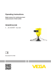
Autoclaved version
Foruseinanautoclave,e.g.forsterilization,theVEGAFLEX83is
available as autoclaved version.
Henceyoucanseparatethehousingfromtheprocessfitting.
Open the slotted nut with a hook wrench and remove the housing in
an upward direction.
Thesideoftheprocessfittingmustbecoveredwithalidafterthe
housing is removed. Screw the enclosed lid with slotted nut onto the
instrumentsideoftheprocessfittingandtightenthenutwithatorque
of 20 Nm.
Make sure that no liquid or contamination penetrates into the housing
or the process side.
18
VEGAFLEX 83 • Foundation Fieldbus
44224-EN-140430
Afterautoclaving,screwthelidoffagainandplacethehousingverticallyonthesideoftheprocessfitting.Tightentheslottednutwitha
torque of 20 Nm.
ø 54 mm
(2.13")
2
65,3 mm
(2.57")
112 mm
(4.84")
183 mm
(7.20")
4 Mounting
3
1
L
øw
øw
DIN DN25 DN32 DN40 / 1" 1 1/2"
DIN DN50 / 2"
DIN DN65 / 3"
ø 50,5
ø 64
ø 91
Fig. 9: Autoclaved version
44224-EN-140430
1 Groovenut
2 Processfitting
3 Coverwithgroovenut
VEGAFLEX 83 • Foundation Fieldbus
19
5 Connecting to power supply
5
Safety instructions
Connecting to power supply
5.1
Preparing the connection
Always keep in mind the following safety instructions:
•
•
Connect only in the complete absence of line voltage
If overvoltage surges are expected, overvoltage arresters should
be installed
Voltage supply
The instrument requires a operating voltage of 9 … 32 V DC. Operating voltage and the digital bus signal are carried on the same two-wire
connection cable. Power is supplied via the H1 power supply.
Connection cable
Connection is carried out with screened cable according to Fieldbus
specification.
Use cable with round cross section for instruments with housing and
cablegland.Toensurethesealeffectofthecablegland(IPprotection
rating),findoutwhichcableouterdiameterthecableglandissuitable
for.
Useacableglandfittingthecablediameter.
Make sure that the entire installation is carried out according to the
Fieldbusspecification.Inparticular,makesurethatthebusisterminated with suitable terminating resistors.
Cable gland ½ NPT
With plastic housing, the NPT cable gland or the Conduit steel tube
must be screwed without grease into the threaded insert.
Max. torque for all housings see chapter "Technicaldata".
Cable screening and
grounding
Make sure that the cable screen and grounding are carried out accordingtoFieldbusspecification.Werecommendtoconnectthe
cable screen to ground potential on both ends.
In systems with potential equalisation, connect the cable screen
directly to ground potential at the power supply unit, in the connection
box and at the sensor. The screen in the sensor must be connected
directly to the internal ground terminal. The ground terminal outside
on the housing must be connected to the potential equalisation (low
impedance).
Connection technology
5.2
Connecting
The voltage supply and signal output are connected via the springloaded terminals in the housing.
Connection to the display and adjustment module or to the interface
adapter is carried out via contact pins in the housing.
20
VEGAFLEX 83 • Foundation Fieldbus
44224-EN-140430
Information:
The terminal block is pluggable and can be removed from the
electronics. To do this, lift the terminal block with a small screwdriver
and pull it out. When reinserting the terminal block, you should hear it
snap in.
5 Connecting to power supply
Connection procedure
Proceed as follows:
1. Unscrew the housing cover
2. If a display and adjustment module is installed, remove it by turning it slightly to the left.
3. Loosen compression nut of the cable entry gland
4. Remove approx. 10 cm (4 in) of the cable mantle, strip approx.
1 cm (0.4 in) of insulation from the ends of the individual wires
5. Insert the cable into the sensor through the cable entry
44224-EN-140430
Fig.10:Connectionsteps5and6-Singlechamberhousing
Fig.11:Connectionsteps5and6-Doublechamberhousing
6. Insert the wire ends into the terminals according to the wiring plan
Information:
Solidcoresaswellasflexiblecoreswithwireendsleevesareinserteddirectlyintotheterminalopenings.Incaseofflexiblecoreswithout
VEGAFLEX 83 • Foundation Fieldbus
21
5 Connecting to power supply
end sleeves, press the terminal from above with a small screwdriver,
the terminal opening is then free. When the screwdriver is released,
the terminal closes again.
Youcanfindfurtherinformationonthemax.wirecross-sectionunder
"Technicaldata/Electromechanicaldata"
7. Check the hold of the wires in the terminals by lightly pulling on
them
8. Connect the screen to the internal ground terminal, connect the
outer ground terminal to potential equalisation
9. Tighten the compression nut of the cable entry gland. The seal
ring must completely encircle the cable
10. Reinsert the display and adjustment module, if one was installed
11. Screw the housing cover back on
Theelectricalconnectionisfinished.
5.3
Electronics and terminal
compartment
Wiring plan, single chamber housing
The following illustration applies to the non-Ex, Ex-ia and Ex-d version.
2
3
0
(+)1
4
1
1
0
Bus
2(-)
5
6
7
8
5
1
Fig.12:Electronicsandterminalcompartment,singlechamberhousing
1
2
3
4
5
Voltage supply, signal output
Contactpinsforthedisplayandadjustmentmoduleorinterfaceadapter
Simulation switch ("1" = mode for simulation release)
For external display and adjustment unit
Groundterminalforconnectionofthecablescreen
5.4
Wiring plan, double chamber housing
The following illustrations apply to the non-Ex as well as to the Ex-ia
version.
44224-EN-140430
22
VEGAFLEX 83 • Foundation Fieldbus
5 Connecting to power supply
Electronics compartment
2
3
1
1
0
0
Bus
(+)1
2(-)
5
6
1
7
8
1
Fig.13:Electronicscompartment,doublechamberhousing
1 Internal connection to the connection compartment
2 Contactpinsforthedisplayandadjustmentmoduleorinterfaceadapter
3 Simulation switch ("on" = simulation mode)
Terminal compartment
2
3
Bus
(+)1
2(-)
5
6
7
8
4
1
Fig.14:Terminalcompartment,doublechamberhousing
1
2
3
4
Voltage supply, signal output
For display and adjustment module or interface adapter
For external display and adjustment unit
Groundterminalforconnectionofthecablescreen
44224-EN-140430
Information:
The use of an external display and adjustment unit and a display and
adjustment module in parallel in the connection compartment is not
supported.
VEGAFLEX 83 • Foundation Fieldbus
23
5 Connecting to power supply
Connection compartment
- Radio module PLICSMOBILE
SIM-Card
Status
Test
USB
(+)1
2(-)
1
Fig.15:ConnectioncompartmentradiomodulePLICSMOBILE
1
Voltage supply
Youcanfinddetailedinformationonconnectioninthesupplementary
instructions "PLICSMOBILEGSM/GPRSradiomodule".
Electronics compartment
5.5
Double chamber housing with DIS-ADAPT
1
2
3
Fig.16:ViewtotheelectronicscompartmentwithDISADAPTforconnectionof
the external display and adjustment unit
1 DIS-ADAPT
2 Internal plug connection
3 Plug connector M12 x 1
Assignment of the plug
connector
4
3
1
2
1
2
3
4
24
Pin 1
Pin 2
Pin 3
Pin 4
VEGAFLEX 83 • Foundation Fieldbus
44224-EN-140430
Fig. 17: View to the plug connector M12 x 1
5 Connecting to power supply
Wire assignment, connection cable
Contact pin
Colour connection cable in the sensor
Terminal, electronics
module
Pin 1
Brown
5
Pin 2
White
6
Pin 3
Blue
7
Pin 4
Black
8
5.6
Wiring plan - version IP 66/IP 68, 1 bar
1
2
Fig. 18: Wire assignment in permanently connected connection cable
1
2
Supplementary electronics - Radio module
PLICSMOBILE
brown (+) and blue (-) to power supply or to the processing system
Shielding
5.7
Supplementary electronics
The radio module PLICSMOBILE is an external GSM/GPRS radio
unit for transmission of measured values and for remote parameter
adjustment.
SIM-Card
Status
Test
USB
(+)1
2(-)
1
Fig.19:RadiomodulePLICSMOBILEintegratedintheconnectioncompartment
1
Voltage supply
Youcanfinddetailedinformationonconnectioninthesupplementary
instructions "PLICSMOBILEGSM/GPRSradiomodule".
44224-EN-140430
5.8
Switch-on phase
After VEGAFLEX 83 is connected to the bus system, the instrument
carries out a self-test for approx. 30 seconds. The following steps are
carried out:
•
•
Internal check of the electronics
Indication of the instrument type, hardware and software version,
measurement loop name on the display or PC
VEGAFLEX 83 • Foundation Fieldbus
25
5 Connecting to power supply
•
•
Indication of the status message "F 105 Determine measured
value" on the display or PC
Statusbytegoesbrieflytofaultvalue
As soon as a plausible measured value is found, it is outputted to the
signal cable. The value corresponds to the actual level as well as the
settings already carried out, e.g. factory settings.
44224-EN-140430
26
VEGAFLEX 83 • Foundation Fieldbus
6 Set up with the display and adjustment module
6
6.1
Set up with the display and adjustment
module
Insert display and adjustment module
The display and adjustment module can be inserted into the sensor
andremovedagainatanytime.Youcanchooseanyoneoffourdifferent positions - each displaced by 90°. It is not necessary to interrupt
the power supply.
Proceed as follows:
1. Unscrew the housing cover
2. Place the display and adjustment module in the requested position onto the electronics and turn to the right until it snaps in
3. Screw housing cover with inspection window tightly back on
Removal is carried out in reverse order.
The display and adjustment module is powered by the sensor, an additional connection is not necessary.
44224-EN-140430
Fig. 20: Installing the display and adjustment module in the electronics compartment of the single chamber housing
VEGAFLEX 83 • Foundation Fieldbus
27
6 Set up with the display and adjustment module
1
2
Fig. 21: Insertion of the display and adjustment module into the double chamber
housing
1 In the electronics compartment
2 Intheconnectioncompartment(withEx-d-iaversionnotpossible)
Note:
Ifyouintendtoretrofittheinstrumentwithadisplayandadjustment
module for continuous measured value indication, a higher cover with
an inspection glass is required.
6.2
Adjustment system
1
2
1 LCdisplay
2 Adjustment keys
Key functions
28
•
[OK] key:
– Move to the menu overview
VEGAFLEX 83 • Foundation Fieldbus
44224-EN-140430
Fig. 22: Display and adjustment elements
6 Set up with the display and adjustment module
•
•
•
– Confirmselectedmenu
– Edit parameter
– Save value
[->] key:
– Presentation, change measured value
– Select list entry
– Select editing position
[+] key:
– Change value of the parameter
[ESC] key:
– Interrupt input
– Jump to next higher menu
Adjustment system
The sensor is adjusted via the four keys of the display and adjustment module. The LC display indicates the individual menu items. The
functions of the individual keys are shown in the above illustration.
Approx. 10 minutes after the last pressing of a key, an automatic reset
tomeasuredvalueindicationistriggered.Anyvaluesnotconfirmed
with [OK] will not be saved.
Switch-on phase
After switching on, the VEGAFLEX 83 carries out a short self-test
where the device software is checked.
The output signal transmits a fault signal during the switch-on phase.
The following information is displayed on the display and adjustment
module during the startup procedure:
•
•
•
•
Measured value indication
Instrument type
Device name
Software version (SW-Ver)
Hardware version (HW-Ver)
With the [->]keyyoucanmovebetweenthreedifferentindication
modes.
Inthefirstview,theselectedmeasuredvalueisdisplayedinlarge
digits.
In the second view, the selected measured value and a corresponding bar graph presentation are displayed.
44224-EN-140430
In the third view, the selected measured value as well as a second
selectable value, e.g. the temperature, are displayed.
Quick setup
6.3
Parameter adjustment - Quick setup
To quickly and easily adapt the sensor to the application, select
the menu item "Quick setup" in the start graphic on the display and
adjustment module.
VEGAFLEX 83 • Foundation Fieldbus
29
6 Set up with the display and adjustment module
Youcanfind"Extendedadjustment"inthenextsub-chapter.
General information
Application
In this menu item, you can select the application. You can choose
between level measurement and interface measurement. You can
also choose between measurement in a vessel or in a bypass or
standpipe.
Level measurement
Medium - dielectric constant
Inthismenuitem,youcandefinethetypeofmedium(product).
Max. adjustment
In this menu item, you can enter the max. adjustment for the level.
Enter the appropriate distance value in m (corresponding to the
percentage value) for the full vessel. The distance refers to the sensor
referenceplane(sealsurfaceoftheprocessfitting).Keepinmindthat
the max. level must lie below the dead band.
Min. adjustment
In this menu item, you can enter the min. adjustment for the level.
Enter the suitable distance value in m for the empty vessel (e.g.
distancefromtheflangetotheprobeend)correspondingtothepercentage value. The distance refers tot he sensor reference plane (seal
surfaceoftheprocessfitting).
Interface measurement
Dielectric constant - upper medium
Inthismenuitem,youcandefinethetypeofmedium(product).
Max. adjustment
In this menu item, you can enter the max. adjustment for the level.
Enter the appropriate distance value in m (corresponding to the
percentage value) for the full vessel. The distance refers to the sensor
referenceplane(sealsurfaceoftheprocessfitting).Keepinmindthat
the max. level must lie below the dead band.
Enter the suitable distance value in m for the empty vessel (e.g.
distancefromtheflangetotheprobeend)correspondingtotheper30
VEGAFLEX 83 • Foundation Fieldbus
44224-EN-140430
Min. adjustment
In this menu item, you can enter the min. adjustment for the level.
6 Set up with the display and adjustment module
centage value. The distance refers tot he sensor reference plane (seal
surfaceoftheprocessfitting).
Max. adjustment - Interface
Carry out the max. adjustment for the interface.
To do this, enter the percentage value and the suitable distance value
in m for the full vessel.
Min. adjustment - Interface
Carry out the min. adjustment for the interface.
To do this, enter the percentage value and the suitable distance value
in m for the empty vessel.
Linearization
Linearization
Alinearizationisnecessaryforallvesselsinwhichthevesselvolume
doesnotincreaselinearlywiththelevel-e.g.ahorizontalcylindrical or spherical tank, when the indication or output of the volume is
required.Correspondinglinearizationcurvesarepreprogrammed
for these vessels. They represent the correlation between the level
percentage and vessel volume.
Thelinearizationappliesforthemeasuredvalueindicationandthe
current output. By activating the suitable curve, the percentage vessel
volume is displayed correctly.
False signal suppression
Highsocketsandinternalvesselinstallationscauseinterferingreflectionsandcaninfluencethemeasurement.
A false signal suppression detects, marks and saves these false
signals so that they are no longer taken into account for the level and
interface measurement. We generally recommend carrying out a false
signal suppression to achieve the best possible accuracy. This should
be done with the lowest possible level so that all potential interfering
reflectionscanbedetected.
Enter the actual distance from the sensor to the product surface.
44224-EN-140430
All interfering signals in this section are detected by the sensor and
stored.
The instrument carries out an automatic false signal suppression
as soon as the probe is uncovered. The false signal suppression is
always updated.
VEGAFLEX 83 • Foundation Fieldbus
31
6 Set up with the display and adjustment module
6.4
Parameter adjustment - Extended adjustment
For technically demanding measuring points, you can carry out
extended settings in "Extendedadjustment".
Main menu
Themainmenuisdividedintofivesectionswiththefollowingfunctions:
Setup: Settings, e.g. medium, application, vessel, adjustment, damping,deviceunits,unitSV2,falsesignalsuppression,linearization
Display: Language setting, settings for the measured value indication
as well as lighting
Diagnosis: Information, e.g. on instrument status, pointer, measurement reliability, simulation, echo curve
Additional adjustments: e.g. date/time, reset, copy sensor data
Info: Instrument name, hardware and software version, date of manufacture, device ID, instrument features
Note:
For optimum adjustment of the measuring point, the individual submenu items in the main menu item "Setup" should be selected one
after the other and provided with the correct parameters. If possible,
go through the items in the given sequence.
The procedure is described below.
The following submenu points are available:
The submenu points described below.
32
In this menu item you select the distance unit and the temperature
unit.
VEGAFLEX 83 • Foundation Fieldbus
44224-EN-140430
Setup - Units
6 Set up with the display and adjustment module
With the distance units you can choose between m, mm and ft and
with the temperature units betwenn °C, °F and K.
Setup - Probe length
In this menu item you can enter the probe length or have the length
determined automatically by the sensor system.
When choosing "Yes", then the probe length will be determined
automatically. When choosing "No", you can enter the probe length
manually.
Setup - Type of medium
In this menu item you can select which type of medium you want to
measure. You can choose between liquid or bulk solid.
Setup - Application - Application
In this menu item, you can select the application. You can choose
between level measurement and interface measurement. You can
also choose between measurement in a vessel or in a bypass or
standpipe.
Note:
Theselectionoftheapplicationhasaconsiderableinfluenceonall
other menu items. Keep in mind that as you continue with the parameter adjustment, individual menu items are only optionally available.
You have the option of choosing the demonstration mode. This mode
is only suitable for test and demonstration purposes. In this mode, the
sensor ignores the parameters of the application and reacts immediately to each change.
44224-EN-140430
Setup - Application - Medium, dielectric constant
Inthismenuitem,youcandefinethetypeofmedium(product).
This menu item is only available if you have selected level measurement under the menu item "Application".
You can choose between the following medium types:
VEGAFLEX 83 • Foundation Fieldbus
33
6 Set up with the display and adjustment module
Setup - Application - Gas
phase
Dielectric constant
Type of medium
Examples
> 10
Water-based liquids
Acids, alcalis, water
3 … 10
Chemical mixtures
Chlorobenzene,nitrolacquer,aniline,
isocyanate, chloroform
<3
Hydrocarbons
Solvents, oils, liquid gas
This menu item is only available, if you have chosen interface measurement under the menu item "Application". In this menu item you can
enter if there is a superimposed gas phase in your application.
Only set the function to "Yes", if the gas phase is permanently present.
Setup - Application - Dielectric constant
This menu item is only available if you have selected interface measurement under the menu item "Application". In this menu item you can
choose the type of medium of the upper medium.
You can enter the dielectric constant of the upper medium directly or
have the value determined by the instrument. To do this you have to
enter the measured or known distance to the interface.
Setup - Max. adjustment
Level
In this menu item you can enter the max. adjustment for the level. With
interface measurement this is the maximum total level.
Adjust the requested percentage value with [+] and store with [OK].
34
VEGAFLEX 83 • Foundation Fieldbus
44224-EN-140430
Enter the appropriate distance value in m (corresponding to the
percentage value) for the full vessel. The distance refers to the sensor
referenceplane(sealsurfaceoftheprocessfitting).Keepinmindthat
the max. level must lie below the dead band.
6 Set up with the display and adjustment module
Setup - Min. adjustment
Level
In this menu item you can enter the min. adjustment for the level. With
interface measurement this is the minimum total level.
Adjust the requested percentage value with [+] and store with [OK].
Enter the suitable distance value in m for the empty vessel (e.g.
distancefromtheflangetotheprobeend)correspondingtothepercentage value. The distance refers tot he sensor reference plane (seal
surfaceoftheprocessfitting).
Setup - Max. adjustment - This menu item is only available if you have selected interface measInterface
urement under the menu item "Application".
You can accept the adjustment of the level measurement also for the
interface measurement. If you select "Yes", the current setting will be
displayed.
44224-EN-140430
If you have selected "No", you can enter the adjustment for the interface separately. Enter the requested percentage value.
For the full vessel, enter the distance value in m matching the percentage value.
VEGAFLEX 83 • Foundation Fieldbus
35
6 Set up with the display and adjustment module
Setup - Min. adjustment Interface
This menu item is only available if you have selected interface measurement under the menu item "Application". If you have selected "Yes"
in the previous menu item (accept adjustment of the level measurement), the current setting will be displayed.
If you have selected "No", you can enter the adjustment for the interface measurement separately.
Enter the respective distance value in m for the empty vessel corresponding to the percentage value.
Setup - False signal suppression
Thefollowingcircumstancescauseinterferingreflectionsandcan
influencethemeasurement:
•
•
High sockets
Vessel installations such as struts
Note:
A false signal suppression detects, marks and saves these false
signals so that they are no longer taken into account for the level and
interface measurement. We generally recommend carrying out a false
signal suppression to achieve the best possible accuracy. This should
be done with the lowest possible level so that all potential interfering
reflectionscanbedetected.
Proceed as follows:
Enter the actual distance from the sensor to the product surface.
All interfering signals in this section are detected by the sensor and
stored.
If a false signal suppression has already been created in the sensor,
the following menu window appears when selecting "False signal
suppression":
36
VEGAFLEX 83 • Foundation Fieldbus
44224-EN-140430
Note:
Check the distance to the product surface, because if an incorrect
(too large) value is entered, the existing level will be saved as a false
echo.Thefillinglevelwouldthennolongerbedetectableinthisarea.
6 Set up with the display and adjustment module
The instrument carries out an automatic false signal suppression
as soon as the probe is uncovered. The false signal suppression is
always updated.
The menu item "Delete" is used to completely delete an already created false signal suppression. This is useful if the saved false signal
suppression no longer matches the metrological conditions in the
vessel.
Setup - Damping
Todampprocess-dependentmeasuredvaluefluctuations,setan
integration time of 0 … 999 s in this menu item.
If you have selected interface measurement under the menu item
"Application", you can adjust the damping for the level and the interface separately.
The default setting is a damping of 0 s.
Setup - Linearization
Alinearizationisnecessaryforallvesselsinwhichthevesselvolume
doesnotincreaselinearlywiththelevel-e.g.ahorizontalcylindrical or spherical tank, when the indication or output of the volume is
required.Correspondinglinearizationcurvesarepreprogrammed
for these vessels. They represent the correlation between the level
percentage and vessel volume.
Thelinearizationappliestothemeasuredvalueindicationandthe
current output. By activating the appropriate curve, the volume percentage of the vessel is displayed correctly. If the volume should not
be displayed in percent but e.g. in l or kg, a scaling can be also set in
the menu item "Display".
44224-EN-140430
Warning:
Ifalinearizationcurveisselected,themeasuringsignalisnolonger
necessarilylineartothefillingheight.Thismustbeconsideredbythe
user especially when adjusting the switching point on the limit signal
transmitter.
In the following, you have to enter the values for your vessel, for
example the vessel height and the socket correction.
For non-linear vessel forms, enter the vessel height und the socket
correction.
For the vessel height, you have to enter the total height of the vessel.
VEGAFLEX 83 • Foundation Fieldbus
37
6 Set up with the display and adjustment module
D
-h
+h
For the socket correction you have to enter the height of the socket
above the upper edge of the vessel. If the socket is lower than the upper edge of the vessel, this value can also be negative.
Fig. 23: Vessel height und socket correction value
D Vessel height
+h Positive socket correction value
-h Negative socket correction value
Lock/release setup - Adjustment
In the menu item "Lock/unlockadjustment", you can protect the
sensorparametersagainstunauthorizedmodification.ThePINis
activated/deactivated permanently.
The following adjustment functions are possible without entering the
PIN:
38
Select menu items and show data
Read data from the sensor into the display and adjustment module.
VEGAFLEX 83 • Foundation Fieldbus
44224-EN-140430
•
•
6 Set up with the display and adjustment module
Caution:
With active PIN, adjustment via PACTware/DTM as well as other
systems is also blocked.
You can change the PIN number under "Additional adjustments PIN".
Display
In the main menu point "Display", the individual submenu points
should be selected subsequently and provided with the correct
parameters to ensure the optimum adjustment of the display options.
The procedure is described in the following.
The following submenu points are available:
The submenu points described below.
Display - Menu language
This menu item enables the setting of the requested national language.
In the delivery status, the sensor is set to the ordered national language.
Display - Displayed value
1
Inthismenuitem,youdefinetheindicationofthemeasuredvalue
onthedisplay.Youcandisplaytwodifferentmeasuredvalues.Inthis
menuitem,youdefinemeasuredvalue1.
The default setting for the displayed value 1 is "Filling height Level".
44224-EN-140430
Display - Displayed value
2
Inthismenuitem,youdefinetheindicationofthemeasuredvalue
onthedisplay.Youcandisplaytwodifferentmeasuredvalues.Inthis
menuitem,youdefinemeasuredvalue2.
The default setting for the displayed value 2 is the electronics temperature.
Display - Backlight
The optionally integrated background lighting can be adjusted via the
adjustment menu. The function depends on the height of the supply
voltage, see "Technicaldata".
VEGAFLEX 83 • Foundation Fieldbus
39
6 Set up with the display and adjustment module
Thelightingisswitchedoffindeliverystatus.
Diagnostics - Device
status
In this menu item, the device status is displayed.
Diagnostics - Peak values The respective min. and max. measured value is saved in the senDistance
sor. The two values are displayed in the menu item "Peak values,
distance".
If you have selected interface measurement under the menu item
"Setup - Application", the peak values of the interface measurement
are displayed in addition to the peak values of the level measurement.
In another window you can carry out a reset of the two peak values
separately.
Diagnostics - Peak values The respective min. and max. measured values are saved in the
Measurement certainty
sensor. The two values are displayed in the menu item "Peak values,
measurement certainty".
Themeasurementcanbeinfluencedbytheprocessconditions.In
this menu item, the measurement certainty of the level measurement
is displayed as percentage value. The higher the value, the more reliable the measurement. Values > 90 % indicate reliable measurement.
If you have selected interface measurement under the menu item
"Setup - Application", the peak values of the interface measurement
are displayed in addition to the peak values of the level measurement.
40
VEGAFLEX 83 • Foundation Fieldbus
44224-EN-140430
In another window you can carry out a reset of the two peak values
separately.
6 Set up with the display and adjustment module
Diagnostics - Peak values The respective min. and max. measured values are saved in the
Additional
sensor. The values are displayed in the menu item "Peak values Additional".
This menu item displays the peak values of the electronics temperature as well as the dielectric constant.
In another window you can carry out a reset of the two peak values
separately.
Diagnostics - Echo curve
The menu item "Echocurve" shows the signal strength of the echoes
over the measuring range in V. The signal strength enables an evaluation of the quality of the measurement.
Withthefollowingfunctionsyoucanzoompartsectionsoftheecho
curve.
•
•
•
44224-EN-140430
Diagnosis - Simulation
"X-Zoom": Zoom function for the meas. distance
"Y-Zoom":1,2,5and10xsignalmagnificationin"V"
"Unzoom":Resetthepresentationtothenominalmeasuringrange
withsinglemagnification
In this menu item you can simulate measured values via the current
output. This allows the signal path to be tested, e.g. through downstream indicating instruments or the input card of the control system.
Selecttherequestedsimulationsizeandadjusttherequestedvalue.
VEGAFLEX 83 • Foundation Fieldbus
41
6 Set up with the display and adjustment module
Caution:
During simulation, the simulated value is outputted as 4 … 20 mA current value and digital HART signal.
Push the [ESC] key to deactivate the simulation.
Information:
The simulation is terminated automatically 60 minutes after the last
key has been pressed.
Diagnostics - Echo curve
memory
With the menu item "Setup" the echo curve it is possible to save at
the time of setup. This is generally recommended; for using the Asset
Management functions it is necessary. If possible, the curve should
be saved with a low level in the vessel.
With this, you can detect signal changes over the operating time. With
the adjustment software PACTware and the PC, the high-resolution
echo curve can be displayed and used to compare the echo curve of
the setup with the actual echo curve.
The function "Echocurvememory" enables storing echo curves of
the measurement.
Under the sub-menu item "Echocurvememory" you can store the
current echo curve.
Parameter settings for recording the echo curve and the settings of
the echo curve itself can be carried out in the adjustment software
PACTware.
With the adjustment software PACTware and the PC the high-resolution echo curve can be displayed and used later on to assess the
quality of the measurement.
Additional settings - PIN
VEGAFLEX 83 • Foundation Fieldbus
44224-EN-140430
42
Enteringa4-digitPINprotectsthesensordataagainstunauthorized
accessandunintentionalmodification.Inthismenuitem,thePINis
displayed or edited and changed. However, this menu item is only
available if adjustment is enabled in the menu "Lock/Releasesetup/
adjustment".
6 Set up with the display and adjustment module
In delivery status, the PIN is "0000".
Additional adjustments Date Time
In this menu item, the internal clock of the sensor is adjusted.
Additional adjustments
- Reset
With a reset, certain parameter adjustments carried out by the user
are reset.
The following reset functions are available:
Delivery status: Restoring the parameter settings at the time of shipmentfromthefactoryincl.theorder-specificsettings.Acreatedfalse
signalsuppression,user-programmablelinearizationcurveaswellas
the measured value memory will be deleted.
Basic settings: Resetting the parameter settings incl. special parameters to the default values of the respective instrument. Any stored
falsesignalsuppression,userprogrammablelinearizationcurveas
well as the measured value memory is deleted.
The following table shows the default values of the instrument. Depending on the instrument version or application, all menu items may
notbeavailableorsomemaybedifferentlyassigned:
44224-EN-140430
Setup
Menu item
Default value
Block adjustment
Released
Measurement loop name
Sensor
Units
Distance unit: mm
Probe length
Length of the probe Ex factory
Type of medium
Liquid
Application
Level in the vessel
Medium, dielectric constant
Water-based, > 10
Superimposed gas phase
Yes
Dielectric constant, upper medium (TS)
1.5
Tube inner diameter
200 mm
Max. adjustment - Level
100 %
VEGAFLEX 83 • Foundation Fieldbus
Modifiedvalue
Temperature unit: °C
43
6 Set up with the display and adjustment module
Menu item
Default value
Max. adjustment - Level
Distance: 0.000 m(d) - note blocking distances
Modifiedvalue
Min. adjustment - Level
0%
Min. adjustment - Level
Distance: Probe length - take dead
band into account
Accept adjustment of the level measurement?
Yes
Max. adjustment - Interface
100 %
Max. adjustment - Interface
Distance: 0.000 m(d) - note blocking distances
Min. adjustment - Interface
0%
Min. adjustment - Interface
Distance: Probe length - take dead
band into account
Integration time - Level
0.0 s
Integration time - Interface
0.0 s
Linearizationtype
Linear
Linearization-Socketcorrection
0 mm
Linearization-Vesselheight
Probe length
Display
Menu item
Default value
Modifiedvalue
Language
Order-specific
Displayed value 1
Filling height Level
Displayed value 2
Electronics temperature
Backlight
Switchedoff
Diagnostics
Menu item
Default value
Status signals - Function control
Switched on
Statussignals-Outofspecification
Switchedoff
Status signals - Maintenance
Switchedoff
Device memory - Echo curve memory
Stopped
Modifiedvalue
Started
Device memory - Measured value memory Measured values
Distance level, percentage value
level, reliability level, electronics
temperature
Device memory - Measured value memory - Recording in time interval
3 min.
Device memory - Measured value memory - Recordingwithmeasuredvaluedifference
15 %
Device memory - Measured value memory - Start
with measured value
Not active
44
44224-EN-140430
Device memory - Measured value memory
VEGAFLEX 83 • Foundation Fieldbus
6 Set up with the display and adjustment module
Menu item
Default value
Device memory - Measured value memory - Stop
with measured value
Not active
Device memory - Measured value memory - Stop
recording when memory is full
Not active
Modifiedvalue
Additional adjustments
Menu item
Default value
PIN
0000
Date
Actual date
Time
Actual time
Time - Format
24 hours
Probe type
Device-specific
Modifiedvalue
Additional adjustments - The instrument settings are copied with this function. The following
Copy instrument settings functions are available:
•
•
Read from sensor: Read data from sensor and store into the
display and adjustment module
Write into sensor: Store data from the display and adjustment
module back to the sensor
The following data or settings for adjustment of the display and adjustment module are saved:
•
•
•
All data of the menu "Setup" and "Display"
In the menu "Additional adjustments" the items "Reset,Date/Time"
Special parameters
The copied data are permanently saved in an EEPROM memory in
the display and adjustment module and remain there even in case of
power failure. From there, they can be written into one or more sensors or kept as backup for a possible electronics exchange.
44224-EN-140430
Note:
Before the data are stored in the sensor, a check is carried out to
determineifthedatafitthesensor.Ifthedatadonotfit,afaultsignal
is triggered or the function is blocked. When data are being written
into the sensor, the display shows which instrument type the data
originate from and which TAG-no. this sensor had.
Additional adjustments Probe type
Inthismenuitemyoucanselectthetypeandsizeofyourprobefrom
a list of all possible probes. This is necessary to adapt the electronics
optimally to the probe.
VEGAFLEX 83 • Foundation Fieldbus
45
6 Set up with the display and adjustment module
Additional adjustments Special parameters
In this menu item you gain access to the protected area where
you can enter special parameters. In exceptional cases, individual
parameterscanbemodifiedinordertoadaptthesensortospecial
requirements.
Change the settings of the special parameters only after having contactedourservicestaff.
Info - Instrument name
In this menu, you read out the instrument name and the instrument
serial number.
Info - Instrument version
In this menu item, the hardware and software version of the sensor is
displayed.
Info - Factory calibration
date
In this menu item, the date of factory calibration of the sensor as well
as the date of the last change of sensor parameters are displayed via
the display and adjustment module or via the PC.
Info - Device ID
Inthismenuitem,theidentificationnumberoftheinstrumentina
Foundation Fieldbus system is shown.
Info - Sensor characteristics
In this menu item, the features of the sensor such as approval, processfitting,seal,measuringrange,electronics,housingandothers
are displayed.
44224-EN-140430
46
VEGAFLEX 83 • Foundation Fieldbus
6 Set up with the display and adjustment module
6.5
Saving the parameter adjustment data
We recommended noting the adjusted data, e.g. in this operating
instructions manual, and archiving them afterwards. They are thus
available for multiple use or service purposes.
If the instrument is equipped with a display and adjustment module,
the data in the sensor can be saved in the display and adjustment
module. The procedure is described in the operating instructions
manual "Display and adjustment module" in the menu item "Copy
sensor data". The data remain there permanently even if the sensor
power supply fails.
The following data or settings for adjustment of the display and adjustment module are saved:
•
•
•
All data of the menu "Setup" and "Display"
In the menu "Additional adjustments" the items "Sensor-specific
units, temperature unit and linearization"
Thevaluesoftheuserprogrammablelinearizationcurve
44224-EN-140430
The function can also be used to transfer settings from one instrument to another instrument of the same type. If it is necessary to
exchange a sensor, the display and adjustment module is inserted
into the replacement instrument and the data are likewise written into
the sensor via the menu item "Copysensordata".
VEGAFLEX 83 • Foundation Fieldbus
47
7 Setup with PACTware
7
7.1
Setup with PACTware
Connect the PC
Via the interface adapter
directly on the sensor
2
1
3
Fig.24:ConnectionofthePCdirectlytothesensorviatheinterfaceadapter
1 USBcabletothePC
2 InterfaceadapterVEGACONNECT
3 Sensor
Prerequisites
7.2
Parameter adjustment with PACTware
For parameter adjustment of the sensor via a Windows PC, the configurationsoftwarePACTwareandasuitableinstrumentdriver(DTM)
according to FDT standard are required. The up-to-date PACTware
version as well as all available DTMs are compiled in a DTM Collection. The DTMs can also be integrated into other frame applications
according to FDT standard.
Note:
To ensure that all instrument functions are supported, you should
always use the latest DTM Collection. Furthermore, not all described
functionsareincludedinolderfirmwareversions.Youcandownload
the latest instrument software from our homepage. A description of
the update procedure is also available in the Internet.
Further setup steps are described in the operating instructions manual "DTMCollection/PACTware" attached to each DTM Collection and
which can also be downloaded from the Internet. Detailed descriptions are available in the online help of PACTware and the DTMs.
44224-EN-140430
48
VEGAFLEX 83 • Foundation Fieldbus
7 Setup with PACTware
Fig.25:ExampleofaDTMview
Standard/Full version
All device DTMs are available as a free-of-charge standard version
and as a full version that must be purchased. In the standard version,
all functions for complete setup are already included. An assistant for
simpleprojectconfigurationsimplifiestheadjustmentconsiderably.
Saving/printing the project as well as import/export functions are also
part of the standard version.
In the full version there is also an extended print function for complete
project documentation as well as a save function for measured value
and echo curves. In addition, there is a tank calculation program as
well as a multiviewer for display and analysis of the saved measured
value and echo curves.
The standard version is available as a download under
www.vega.com/downloads and "Software". The full version is available on CD from the agency serving you.
7.3
Set up with the quick setup
The quick setup is another option for parameter adjustment of the
sensor. It allows fast, convenient adjustment of the most important
parameters to adapt the sensor quickly to standard applications. To
use it, select the function "Quick setup" in the start screen.
44224-EN-140430
General information
VEGAFLEX 83 • Foundation Fieldbus
49
7 Setup with PACTware
Fig. 26: Select quick setup
1 Quick setup
2 Extendedadjustment
3 Maintenance
Quick setup
With quick setup you can carry out the parameter adjustment of
VEGAFLEX 83 for your application in just a few simple steps. The
assistant-driven adjustment includes the basic settings for simple,
reliable setup and commissioning.
Information:
If the function is inactive, then possibly no instrument is connected.
Check the connection to the instrument.
Extended adjustment
With the extended adjustment, you carry out the parameter adjustment for the instrument via the clear menu structure in the DTM
(Device Type Manager). This enables additional and special settings
overandabovethoseofferedbyquicksetup.
Maintenance
Under the menu item "Maintenance" you get comprehensive and
important support for servicing and maintenance. You can call up
diagnostic functions and carry out an electronics exchange or a
software update.
Click to the button "Quick setup", to start the assistant-driven adjustmentforasimplifiedandreliablesetup.
Step 1
Instrumentconfiguration
Device name
Here,youcanfindtheinstrumentname.Youcannotchangethisline
becausetheinstrumentnameisunmodifiablysavedintheinstrument.
50
VEGAFLEX 83 • Foundation Fieldbus
44224-EN-140430
Start quick setup
7 Setup with PACTware
Serial number
Here,youcanfindtheserialnumberofyourinstrument.Youcannot
changethislinebecausetheserialnumberisunmodifiablysavedin
the instrument.
Measurement loop name
Here you can enter a suitable measurement loop name for your VEGAFLEX 83. You can enter a name with max. 19 characters. You can
use capital and small letters as well as numbers. The following special
characters are also possible: + - . : , ( ) / < >
Probelengthmodified?
Ifyouhavemodifiedtheprobelength,thismustbeenteredinthe
selectionfield.
•
•
If you select "No", then the instrument uses automatically the
preset length of the default setting.
If you select "Yes",thenyoucanenterinanotherfieldthemodified
length of the instrument.
Probe length L from seal surface
Ifyouhavemodifiedthelengthoftheprobe,youcanenterinthisfield
themodifiedprobelength.Keeptheselectedunitinmind.
Determine probe length automatically
If you do not know the probe length, you can have the length of the
probe determined automatically. The requirement for this is a probe
unrestricted and not covered by the medium.
Click to "Carryoutnow", to start the automatic length determination.
Step 2
Application
Type of medium
Here you can see which type of medium your instrument is suitable
for. If this function is inactive, the medium type your instrument is suitable for was already preset.
Information:
In special cases you can change the type of medium. This setting can
be changed under "Extendedadjustment".
Application
Inthisfieldyoucanselecttheapplicationyouwanttouseyourinstrument for. You have the following selection options:
44224-EN-140430
•
•
•
•
•
Level in the vessel
Level in the bypass/standpipe
Interface in the vessel
Interface in the bypass/standpipe
Demonstration mode
Level measurement: If you select "Level", you can select the propertiesofthemediuminanotherfield.
Interface measurement: If you select "Interface", the instrument needs
more information, such as the distance to the interface, the dielectric
constant of the upper medium or whether or not there is a superimposed gas phase.
VEGAFLEX 83 • Foundation Fieldbus
51
7 Setup with PACTware
Demonstration mode: This mode is only suitable for test and demonstration purposes. In this mode, the sensor ignores all parameters
and reacts immediately to all measured value changes within the
measuring range.
Application - Level measurement
The level measurement refers to the product surface which is the limit
to the gas phase.
As a standard feature, the instrument is set to level measurement of
liquids. You can switch over the instrument to the measurement of
bulk solids.
•
•
Liquids
– Solvents, oils, LPG - dielectric constant < 3
– Chemical mixtures - dielectric constant 3 … 10
– Water-based - dielectric constant > 10
Bulk solids
– Dusts, wood chips - dielectric constant < 1.5
– Granules, dusts, powders - dielectric constant 1.5 … 3
– Cereals,flour-dielectricconstant>3
Application - Interface measurement
The interface measurement refers to the phase limit between two
liquids. The total level is also available as a measured value.
•
•
Step 3
Adjustment
Superimposed gas phase present
– Check if there is a superimposed gas phase in the vessel. This
is always the case if the total level never touches the process
fitting.
Properties
– Here you can enter the dielectric constant of the upper medium
– As an alternative you can enter the distance to the interface
Adjustment for the level measurement
If you have selected level measurement in the previous menu, then
you can enter the values for the min. and max. adjustment. The value
to be entered refers to the distance from the sealing surface of the
processfitting(sensorreferenceplane)tothesurfaceoftheproduct.
Adjustment for the level and interface measurement
If you have selected interface measurement in the previous menu,
then you can enter the values for the min. and max. adjustment of
level and interface or accept the values of the level measurement. The
entered value refers to the distance from the sealing surface of the
processfitting(sensorreferenceplane)tothetotallevelorinterface.
Linearizationisrequiredifthemeasuredvalueshouldbeoutputted
inproportiontothevolumeandnotthelevel.Thelinearizationacts
identicallyonthelevelandtheinterfacemeasurement.Youcanfind
furtherlinearizationtypesintheextendedadjustment.
If you have a non-linear vessel, you can select here the respective
linearizationcurve.
•
52
Linear
VEGAFLEX 83 • Foundation Fieldbus
44224-EN-140430
Step 4
Linearization
7 Setup with PACTware
•
•
Spherical tank
Horizontalcylindricaltank
•
•
Height of the socket h
Vessel height D
You must enter the following vessel dimensions with non-linear conditions:
Step 5
Sensor optimization
Thesesettingsallowyoutooptimizethesensor.Withthemyoucan
compare a sounded distance with the indicated value and correct it, if
necessary.
Probe immersed in the liquid (covered)
Select whether or not the probe is immersed in the medium.
Measured distance to the medium
If the probe is immersed in the medium, you can enter here the measured distance to the medium.
Displayeddistancecorrect?
Is the displayed distance value correct? If you have the possibility, you
can enter here the sounded distance to the medium.
False signal suppression
With this function you can carry out the automatic false signal suppression. We recommend carrying out false signal suppression in any
case.
Step 6
Additional settings
Whenthesetupoftheinstrumentisfinished,additionalsettingscan
be made. These are various backups and the locking of the instrument against unauthorised or inadvertent adjustment.
Prepareabackupfileoftheinstrumentparameteradjustment?
For backup purposes, the current parameter adjustment of the instrumentisstoredinafile.Youcanusethisfilelaterontorestorethe
instrument parameter adjustment. The complete data set is downloaded from the device. This procedure can last several minutes.
44224-EN-140430
Createinstrumentdocumentation?
ThisfunctionisusedtoprintorcreateaPDFfileofthecurrentparameteradjustment.ToreadthePDFfile,youneedasuitableprogram
(forexampleAcrobatReader).ToprintorcreatethePDFfile,alldata
are downloaded from the device. For this function, the full version
of the DTM Collection is required. This procedure can last several
minutes.
Storeechocurveofthesetupinthesensor?
Have you completed the initial setup of the instrument? In such case,
we recommend storing the current signal conditions in the device for
later instrument tests and diagnostics.
LockadjustmentwithPINaftersetting?
The instrument is locked with the current PIN. A parameter adjustment is possible only after the PIN is entered again.
VEGAFLEX 83 • Foundation Fieldbus
53
7 Setup with PACTware
7.4
Saving the parameter adjustment data
We recommend documenting or saving the parameter adjustment
data via PACTware. That way the data are available for multiple use or
service purposes.
44224-EN-140430
54
VEGAFLEX 83 • Foundation Fieldbus
8 Set up with other systems
8
8.1
Set up with other systems
DD adjustment programs
Device descriptions as Enhanced Device Description (EDD) are
available for DD adjustment programs such as, for example, AMS™
and PDM.
Thefilescanbedownloadedatwww.vega.com/downloads under
"Software".
8.2
Field Communicator 375, 475
Device descriptions for the instrument are available as EDD for parameter adjustment with the Field Communicator 375 or 475.
44224-EN-140430
For the integration of the EDD in the Field Communicator 375 or 475,
the software "Easy Upgrade Utility" is required which is available from
the manufacturer. This software is updated via the Internet and new
EDDs are automatically taken over into the device catalogue of this
software after they are released by the manufacturer. They can then
be transferred to a Field Communicator.
VEGAFLEX 83 • Foundation Fieldbus
55
9 Diagnostics and service
9
Diagnostics and service
9.1
Maintenance
9.2
Diagnosis memory
If the device is used correctly, no maintenance is required in normal
operation.
The instrument has several memories which are available for diagnosis purposes. The data remain even with voltage interruption.
Measured value memory
Up to 100,000 measured values can be stored in the sensor in a ring
memory. Each entry contains date/time as well as the respective
measured value. Storable values are for example:
•
•
•
•
•
•
•
•
Distance
Filling height
Percentage value
Lin. percent
Scaled
Current value
Meas. reliability
Electronics temperature
When the instrument is shipped, the measured value memory is
active and stores distance, measurement certainty and electronics
temperature every 3 minutes.
In "Extended adjustment" you can select the respective measured
values.
The requested values and recording conditions are set via a PC with
PACTware/DTM or the control system with EDD. Data are thus read
out and also reset.
Event memory
Up to 500 events are automatically stored with a time stamp in the
sensor (non-deletable). Each entry contains date/time, event type,
event description and value. Event types are for example:
•
•
•
•
Modificationofaparameter
Switch-onandswitch-offtimes
Status messages (according to NE 107)
Error messages (according to NE 107)
The data are read out via a PC with PACTware/DTM or the control
system with EDD.
Echo curve memory
The echo curves are stored with date and time and the corresponding
echo data. The memory is divided into two sections:
•
•
56
PC with PACTware/DTM
Control system with EDD
VEGAFLEX 83 • Foundation Fieldbus
44224-EN-140430
Echo curve of the setup: This is used as reference echo curve for
the measurement conditions during setup. Changes in the measurement conditions during operation or buildup on the sensor can thus
berecognized.Theechocurveofthesetupisstoredvia:
9 Diagnostics and service
•
Display and adjustment module
•
•
•
PC with PACTware/DTM
Control system with EDD
Display and adjustment module
Further echo curves: Up to 10 echo curves can be stored in a ring
bufferinthismemorysection.Furtherechocurvesarestoredvia:
9.3
Status messages
The instrument features self-monitoring and diagnostics according
to NE 107 and VDI/VDE 2650. In addition to the status messages in
the following tables there are more detailed error messages available
under the menu item "Diagnostics" via the display and adjustment
module, PACTware/DTM and EDD.
Status messages
The status messages are divided into the following categories:
•
•
•
•
Failure
Function check
Outofspecification
Maintenance requirement
and explained by pictographs:
1
2
3
4
Fig. 27: Pictographs of the status messages
1
2
3
4
Failure - red
Outofspecification-yellow
Function check - orange
Maintenance - blue
Failure: Due to a malfunction in the instrument, a failure message is
outputted.
This status message is always active. It cannot be deactivated by the
user.
Function check: The instrument is in operation, the measured value
is temporarily invalid (for example during simulation).
44224-EN-140430
This status message is inactive by default. It can be activated by the
user via PACTware/DTM or EDD.
Outofspecification: The measured value is unstable because the
instrumentspecificationisexceeded(e.g.electronicstemperature).
This status message is inactive by default. It can be activated by the
user via PACTware/DTM or EDD.
Maintenance:Duetoexternalinfluences,theinstrumentfunction
islimited.Themeasurementisaffected,butthemeasuredvalueis
VEGAFLEX 83 • Foundation Fieldbus
57
9 Diagnostics and service
still valid. Plan in maintenance for the instrument because a failure is
expected in the near future (e.g. due to buildup).
This status message is inactive by default. It can be activated by the
user via PACTware/DTM or EDD.
Failure (failure)
The following table shows the codes and text messages of the status
message "Failure" and provides information on causes as well as
corrective measures.
Code
Text message
Rectification
PA DevSpec
Diagnosis
F013
– Sensor does not
– Check or correct
Bit 0
detect an echo during
installation and/or
operation
parameter adjustment
– Antenna system con- – Clean or exchange
taminated or defective
process component or
antenna
F017
– Adjustment not within
specification
F025
– Index markers are not – Checklinearization
continuously rising, for
table
example illogical value – Delete table/Create
pairs
new
Bit 2
F036
– Failed or interrupted
software update
– Repeat software
update
– Check electronics
version
– Exchanging the electronics
– Send instrument for
repair
Bit 3
F040
– Hardware defect
– Exchanging the electronics
– Send instrument for
repair
Bit 4
F080
– General software error – Disconnect operating
voltagebriefly
Bit 5
F105
– The instrument is still – Wait for the end of the Bit 6
in the start phase, the
switch-on phase
measured value could – Duration depending
not yet be determined
on the version and
parameter adjustment
up to approximately
3 min.
F113
– Error in the internal
instrument communication
no measured value
available
Adjustment
span too
small
Error in the
linearization table
No operable
software
Error in the
electronics
Determine
measured
value
– Change adjustment
according to the limit
values(difference
between min. and
max.≥10mm)
– Disconnect operating
voltagebriefly
– Send instrument for
repair
Bit 1
Bit 7
VEGAFLEX 83 • Foundation Fieldbus
44224-EN-140430
Communication error
58
Cause
9 Diagnostics and service
Code
Cause
F125
– Temperature of the
– Check ambient temelectronics in the nonperature
specifiedsection
– Isolate electronics
– Use instrument with
higher temperature
range
Bit 8
F260
– Error in the calibration carried out in the
factory
– Error in the EEPROM
– Exchanging the electronics
– Send instrument for
repair
Bit 9
– Repeat setup
– Repeat reset
Bit 10
Text message
Impermissible
electronics
temperature
Error in the
calibration
– Error during setup
Error in the – False signal suppression faulty
configura– Error when carrying
tion
out a reset
F264
– Adjustment not within – Check or correct
Bit 11
the vessel height/
installation and/or
measuring range
parameter adjustment
– Max. measuring range – Use an instrument
of the instrument not
with bigger measuring
sufficient
range
F265
Measurement
function
disturbed
– Sensor no longer
– Check operating
carries out a measurevoltage
ment
– Carry out a reset
– Operating voltage
– Disconnect operating
too low
voltagebriefly
Bit 12
F267
– Sensor cannot start
-
Installation/Setup
error
No executable sensor
software
Code
Cause
Rectification
C700
– A simulation is active
– Finish simulation
– Wait for the automatic end
after 60 mins.
Simulation active
44224-EN-140430
– Exchanging the electronics
– Send instrument for
repair
The following table shows the error codes and text messages in the
status message "Function check" and provides information on causes
as well as corrective measures.
Text message
Outofspecification
PA DevSpec
Diagnosis
F261
Function check
Rectification
The following table shows the error codes and text messages in the
status message "Outofspecification" and provides information on
causes as well as corrective measures.
VEGAFLEX 83 • Foundation Fieldbus
59
9 Diagnostics and service
Code
Cause
S600
Impermissible electronics
temperature
– Temperature of the elec– Check ambient temperature
tronicsinthenon-specified – Isolate electronics
section
– Use instrument with higher
temperature range
S601
– Dangerofvesseloverfilling
– Make sure that there is no
furtherfilling
– Check level in the vessel
S603
– Operating voltage below
specifiedrange
– Check electrical connection
– if necessary, increase
operating voltage
Text message
Overfilling
Impermissible operating
voltage
Maintenance
The following table shows the error codes and text messages in the
status message "Maintenance" and provides information on causes
as well as corrective measures.
Cause
Rectification
M500
– With the reset to delivery
status, the data could not
be restored
– Repeat reset
– LoadXMLfilewithsensor
data into the sensor
M501
– Hardware error EEPROM
– Exchanging the electronics
– Send instrument for repair
M502
– Hardware error EEPROM
– Exchanging the electronics
– Send instrument for repair
M503
Reliability too
low
– The echot/noise ratio is the
small for a reliable measurement
– Check installation and
process conditions
– Clean the antenna
– Change polarisation direction
– Use instrument with higher
sensitivity
M504
– Hardware defect
– Check connections
– Exchanging the electronics
– Send instrument for repair
Error with the
reset delivery
status
Error in the
non-active
linearization
table
Error in the
diagnosis
memory
Error on an
device interface
VEGAFLEX 83 • Foundation Fieldbus
44224-EN-140430
Code
Text message
60
Rectification
9 Diagnostics and service
Code
Cause
Rectification
M505
– Level echo can no longer
be detected
– Clean the antenna
– Use a more suitable
antenna/sensor
– Remove possible false
echoes
– Optimizesensorposition
and orientation
Text message
No echo available
9.4
Rectify faults
Reaction when malfunctions occur
The operator of the system is responsible for taking suitable measures to rectify faults.
Procedure for fault rectification
Thefirstmeasuresare:
•
•
•
Evaluation of fault messages, for example via the display and
adjustment module
Checking the output signal
Treatment of measurement errors
Further comprehensive diagnostics options are available with a PC
with PACTware and the suitable DTM. In many cases, the reasons can
bedeterminedinthiswayandfaultsrectified.
Treatment of measurement errors
The below tables show typical examples for application-relevant
measurement errors. There are two measurement errors:
•
•
•
Constant level
Filling
Emptying
Level
The images in column "Errorpattern" show the real level with a broken line and the level displayed by the sensor as a continuous line.
1
2
0
time
44224-EN-140430
Fig.28:Thebrokenline1showsthereallevel,thecontinuousline2showsthe
level displayed by the sensor
Note:
• Wherever the sensor displays a constant value, the reason could
also be the fault setting of the current output to "Hold value"
• In case of a too low level indication, the reason could be a line
resistance that is too high
VEGAFLEX 83 • Foundation Fieldbus
61
9 Diagnostics and service
Measurement error with constant level
1. Measured value
shows a too low or too
high level
Error pattern
Level
Fault description
0
Level
2. Measured value
jumps towards 100 %
time
0
time
Cause
Rectification
– Min./max. adjustment not
correct
– Adapt min./max. adjustment
– Wronglinearizationcurve
– Adaptlinearizationcurve
– Running time error (small
measurement error close to
100 %/serious error close to
0 %)
– Repeat setup
– Due to the process, the amplitude of the product echo sinks
– A false signal suppression was
not carried out
– Carry out a false signal suppression
– Amplitude or position of a
false signal has changed (e.g.
buildup); false signal suppression no longer matches
– Determine the reason for the
changed false signals, carry out
false signal suppression, e.g.
with buildup
Cause
Rectification
Measurementerrorduringfilling
3. Measured value remains in the area of the
bottomduringfilling
Error pattern
0
5. Measured value
jumps sporadically to
100%duringfilling
Level
time
0
0
– Check parameters, change if
necessary, e.g. in dosing vessel, reactor
– Changing condensation or
contamination on the probe
– Carry out a false signal suppression
time
Level
6. Measured value
jumpsto≥100%or
0 m distance
– Turbulence on the product
surface,quickfilling
time
Level
4. Measured value remains momentarily
unchangedduringfilling and then jumps to
the correct level
– Echo from the probe end larger – Check parameter "Medium"
than the product echo, for
and "Vessel height", adapt if
example, with products with
necessary
εr < 2.5 oil-based, solvents, etc.
Level
Fault description
0
time
– Level echo is no longer
– Eliminate false signals in the
detected in the close range
close range
due to false signals in the close – Check installation conditions
range. The sensor goes into
– Ifpossible,switchoffthefuncoverfillprotectionmode.The
tion"Overfillprotection"
max. level (0 m distance) as
well as the status message
"Overfillprotection"areoutputted.
44224-EN-140430
62
VEGAFLEX 83 • Foundation Fieldbus
9 Diagnostics and service
Measurement error during emptying
7. Measured value remains unchanged in
the close range during
emptying
Error pattern
0
time
0
Treatment of measurement errors with bulk
solids
Rectification
– Stored false signals in this
position are larger than the
level echo
Level
8. Measured value remains reproducible
in one position during
emptying
Cause
– False echo larger than the level – Eliminate false signals in the
echo
close range
– Level echo too small
– Remove contamination on the
probe. After having removed
the source of the false signals,
the false signal suppression
must be deleted.
– Carry out a new false signal
suppression
Level
Fault description
– Delete false signal memory
– Carry out a new false signal
suppression
time
The below tables show typical examples for application-relevant
measurement errors with bulk solids. There are two measurement
errors:
•
•
•
Constant level
Filling
Emptying
Level
The images in column "Errorpattern" show the real level with a broken line and the level displayed by the sensor as a continuous line.
1
2
0
1
2
time
Real level
Level displayed by the sensor
Notes:
•
•
Wherever the sensor displays a constant value, the reason could
also be the fault setting of the current output to "Hold value"
In case of a too low level indication, the reason could be a line
resistance that is too high
Measurement error with constant level
1. Measured value
shows a too low or too
high level
Error pattern
Level
44224-EN-140430
Fault description
0
Cause
Rectification
– Min./max. adjustment not
correct
– Adapt min./max. adjustment
– Wronglinearizationcurve
– Adaptlinearizationcurve
time
VEGAFLEX 83 • Foundation Fieldbus
63
9 Diagnostics and service
2. Measured value
jumps towards 100 %
Error pattern
Level
Fault description
0
time
Cause
Rectification
– Due to the process, the amplitude of the product echo sinks
– A false signal suppression was
not carried out
– Carry out a false signal suppression
– Amplitude or position of a
false echo has changed (e.g.
condensation, buildup); false
signal suppression no longer
matches
– Determine the reason for the
changed false echoes, carry
out false signal suppression,
e.g. with condensation
Cause
Rectification
Measurementerrorduringfilling
3. Measured value
jumps towards 0 %
duringfilling
Error pattern
Level
Fault description
0
time
– Amplitude of a multiple echo
– Check parameter "Application",
(vessel top - product surface) is
especially vessel top, type
larger than the level echo
of medium, dished end, high
dielectric constant, adapt if
necessary
– The level echo cannot be distin- – In case of interferences due to
guished from the false echo at
installations in the close range:
a false echo position (jumps to
Change polarisation direction
multiple echo)
– Chose a more suitable installation position
4. Measured valuefluctuatesaround
10 … 20 %
Level
– Transversereflectionfroman
extraction funnel, amplitude of
thetransversereflectionlarger
than the level echo
5. Measured value
jumps sporadically to
100%duringfilling
time
Level
0
0
time
– Direct sensor to the opposite
funnel wall, avoid crossing with
thefillingstream
– Various echoes from an uneven – Check parameter "Type of
product surface, e.g. a material
medium" and adapt, if necescone
sary
– Optimizeinstallationposition
and sensor orientation
– Reflectionsfromtheproduct
surface via the vessel wall
(deflection)
– Select a more suitable installationposition,optimizesensor
orientation, e.g. with a swivelling holder
– Varying condensation or contamination on the antenna
– Carry out a false signal suppression or increase false
signal suppression with condensation/contamination in the
close range by editing
– With bulk solids use radar sensor with purging air connection
orflexibleantennacover
44224-EN-140430
64
VEGAFLEX 83 • Foundation Fieldbus
9 Diagnostics and service
Measurement error during emptying
7. Measured value
jumps sporadically towards 100 % during
emptying
8. Measured valuefluctuatesaround
10 … 20 %
Error pattern
Cause
Level
0
0
0
Rectification
– False echo larger than the level – Remove false echoes in the
echo
close range. Check: Antenna
must protrude out of the socket
– Level echo too small
– Remove contamination on the
antenna
– In case of interferences due to
installations in the close range:
Change polarisation direction
– After removing the false echoes, the false signal suppression must be deleted. Carry out
a new false signal suppression
time
– Varying condensation or contamination on the antenna
Level
6. Measured value remains unchanged in
the close range during
emptying
time
– Carry out false signal suppression or increase false signal
suppression in the close range
by editing
– With bulk solids use radar sensor with purging air connection
orflexibleantennacover
– Various echoes from an uneven – Check parameter "Type of
product surface, e.g. an extracmedium" and adapt, if necestion funnel
sary
– Optimizeinstallationposition
– Reflectionsfromtheproduct
and sensor orientation
surface via the vessel wall
Level
Fault description
time
(deflection)
Reaction after fault rectification
Depending on the reason for the fault and the measures taken, the
steps described in chapter "Setup" must be carried out again or must
be checked for plausibility and completeness.
24 hour service hotline
Should these measures not be successful, please call in urgent cases
the VEGA service hotline under the phone no. +49 1805 858550.
The hotline is also available outside normal working hours, seven
days a week around the clock.
Sinceweofferthisserviceworldwide,thesupportisprovidedin
English. The service itself is free of charge, the only costs involved are
the normal call charges.
9.5
Exchanging the electronics module
If the electronics module is defective, it can be replaced by the user.
44224-EN-140430
In Ex applications, only instruments and electronics modules with appropriate Ex approval may be used.
If there is no electronics module available on site, the electronics
module can be ordered through the agency serving you. The electronicsmodulesareadaptedtotherespectivesensoranddifferinsignal
output or voltage supply.
The new electronics module must be loaded with the default settings
of the sensor. These are the options:
VEGAFLEX 83 • Foundation Fieldbus
65
9 Diagnostics and service
•
•
In the factory
Or on site by the user
In both cases, the serial number of the sensor is needed. The serial
numbers are stated on the type label of the instrument, on the inside
of the housing as well as on the delivery note.
Whenloadingonsite,firstofalltheorderdatamustbedownloaded
from the Internet (see operating instructions manual "Electronics
module").
Caution:
Alluser-specificsettingsmustbeenteredagain.Hence,youhaveto
carry out a new setup after the electronics exchange.
If you have stored the data of the parameter adjustment during the
firstsetupofthesensor,youcantransferthesetothereplacement
electronics module. A new setup is no more necessary.
Exchanging the rod
9.6
Exchanging the rod
The rod (meas. part) of the probe can be shortened, if necessary. To
loosen the meas. rod you need a fork spanner with spanner width 10.
Caution:
Remember that the polished rod of the food version is very sensitive
to damage and scratching. Use special tools in order to avoid damaging the surface.
1. Loosentherodbyapplyingaforkspannertotheflatsurfaces
(SW10),providecounterforcemanuallyontheprocessfitting
2. Twistofftheloosenedmeasuringrodmanually
3. Shift the attached new seal ring onto the thread.
4. Screw the new rod carefully by hand to the thread on the process
fitting.
5. Exertcounterforcemanuallyandtightentherodontheflatsurfaces with a torque of 6 Nm (4.43 lbf ft).
44224-EN-140430
66
VEGAFLEX 83 • Foundation Fieldbus
9 Diagnostics and service
1
Fig.46:Exchangingthemeasuringrod
1
Seal ring
Information:
Pleasemaintainthespecifiedtorquesothatthemax.tensilestrength
remains.
6. Enter new probe length and if necessary the new probe type and
then carry out a fresh adjustment (see "Setupprocedure,Carryingoutmin.adjustment-Carryingoutmax.adjustment").
9.7
Software update
The following components are required to update the instrument
software:
44224-EN-140430
•
•
•
•
•
Instrument
Voltage supply
Interface adapter VEGACONNECT
PC with PACTware
Currentinstrumentsoftwareasfile
Youcanfindthecurrentinstrumentsoftwareaswellasdetailed
information on the procedure under "www.vega.com/downloads" and
"Software".
Caution:
Instruments with approvals can be bound to certain software versions.
Thereforemakesurethattheapprovalisstilleffectiveafterasoftware
update is carried out.
VEGAFLEX 83 • Foundation Fieldbus
67
9 Diagnostics and service
Youcanfinddetailedinformationatwww.vega.com/downloads and
"Approvals".
9.8
How to proceed if a repair is needed
Youcanfindarepairformaswellasdetailedinformationonhowto
proceed at www.vega.com/downloads and "Formsandcertificates".
By doing this you help us carry out the repair quickly and without having to call back for needed information.
If a repair is necessary, please proceed as follows:
•
•
•
•
Printandfilloutoneformperinstrument
Clean the instrument and pack it damage-proof
Attach the completed form and, if need be, also a safety data
sheet outside on the packaging
Please contact the agency serving you to get the address for
thereturnshipment.Youcanfindtheagencyonourhomepage
www.vega.com.
44224-EN-140430
68
VEGAFLEX 83 • Foundation Fieldbus
10 Dismounting
10 Dismounting
10.1 Dismounting steps
Warning:
Before dismounting, be aware of dangerous process conditions such
as e.g. pressure in the vessel or pipeline, high temperatures, corrosive or toxic products etc.
Take note of chapters "Mounting" and "Connectingtopowersupply"
and carry out the listed steps in reverse order.
10.2 Disposal
The instrument consists of materials which can be recycled by specialised recycling companies. We use recyclable materials and have
designed the parts to be easily separable.
Correctdisposalavoidsnegativeeffectsonhumansandtheenvironment and ensures recycling of useful raw materials.
Materials: see chapter "Technicaldata"
If you have no way to dispose of the old instrument properly, please
contact us concerning return and disposal.
44224-EN-140430
WEEE directive 2002/96/EG
This instrument is not subject to the WEEE directive 2002/96/EG and
the respective national laws. Pass the instrument directly on to a specialised recycling company and do not use the municipal collecting
points. These may be used only for privately used products according
to the WEEE directive.
VEGAFLEX 83 • Foundation Fieldbus
69
11 Supplement
11 Supplement
11.1 Technical data
General data
316L corresponds to 1.4404 or 1.4435
Materials, wetted parts
Ʋ Processfitting
Ʋ Process seal on the instrument side
(rod leadthrough)
Ʋ Process seal
316L and PEEK
FFKM(Kalrez6221),EPDM(Freudenberg70EPDM 291), FEPM (Vi 602 Extreme-ETP, Messrs. COG)
On site
Ʋ Rod: ø 8 mm (0.315 in) - polished
316L (only 1.4435) - according to Basle Standard
Ʋ Polished (Basle Standard)
Ra < 0.76 µm (3-5 in)
Surface quality1)
Ʋ Electropolished (Basle Standard)
Ra < 0.38 µm (1.5-5 in)
Ʋ Plastic housing
plastic PBT (Polyester)
Materials, non-wetted parts
Ʋ Aluminium die-casting housing
Ʋ Stainless steel housing - precision
casting
Ʋ Stainless steel housing, electropolished
Ʋ Seal between housing and housing
cover
Ʋ Inspection window in housing cover
(optional)
Ʋ Ground terminal
Ohmic contact
Processfittings
Ʋ Clamp
Aluminium die-casting AlSi10Mg, powder-coated - basis:
Polyester
316L
316L
NBR (stainless steel housing, precision casting), silicone
(aluminium/plastic housing; stainless steel housing,
electropolished)
Polycarbonate (with Ex d version: glass)
316L
Betweengroundterminal,processfittingandprobe
from 2"
Ʋ Slotted nut
from DN 32 PN 40
Ʋ Instrument weight (depending on
processfitting)
approx. 0.8 … 8 kg (0.176 … 17.64 lbs)
Weight
Ʋ Rod: ø 8 mm (0.315 in) - polished
approx.400g/m(4.3oz/ft)
Ʋ Rod: ø 8 mm (0.315 in) - polished
up to 4 m (13.12 ft)
Probe length L (from seal surface)
Lateral load with rod: ø 8 mm (0.315 in)
- polished
1)
70
±1 mm + 0.05 % of the rod length
10 Nm (7.38 lbf ft)
All wetted parts
VEGAFLEX 83 • Foundation Fieldbus
44224-EN-140430
Ʋ Trimming accuracy - rod
11 Supplement
Torque for exchangeable rod probe (in
theprocessfitting)
4.5 Nm ±0.5 (3.32 lbf ft)
Torque for NPT cable glands and Conduit tubes
Ʋ Plastic housing
max. 10 Nm (7.376 lbf ft)
Ʋ Aluminium/Stainless steel housing
max. 50 Nm (36.88 lbf ft)
Input variable
Measured variable
Level of liquids
Min. dielectric constant of the medium
εr≥1.6
1
4
2
3
5
Fig.47:Measuringranges-VEGAFLEX83
1
2
3
4
5
Reference plane
Probe length L
Measuring range (default setting refers to the measuring range in water)
Upper dead band (see diagrams under Accuracy - grey section)
Lower dead band (see diagrams under Accuracy - grey section)
Output variable
Output
Ʋ Signal
44224-EN-140430
Ʋ Physical layer
Damping (63 % of the input variable)
Channel Numbers
Ʋ Channel 1
Ʋ Channel 8
Ʋ Channel 9
VEGAFLEX 83 • Foundation Fieldbus
digital output signal, Foundation Fieldbus protocol
according to IEC 61158-2
0 … 999 s, adjustable
Process value
Electronics temperature
Count rate
71
11 Supplement
Transmission rate
Current value
Ʋ Non-Ex and Ex ia instrument
Ʋ Ex-d instruments
Resolution, digital
31.25 Kbit/s
10 mA, ±0.5 mA
16 mA, ±0.5 mA
> 1 mm (0.039 in)
Accuracy (according to DIN EN 60770-1)
Process reference conditions according to DIN EN 61298-1
Ʋ Temperature
Ʋ Relative humidity
Ʋ Air pressure
Installation reference conditions
Ʋ Min. distance to installations
Ʋ Vessel
Ʋ Medium
Ʋ Installation
Sensor parameter adjustment
Typical deviation - Interface measurement
Typical deviation - Total level interface
measurement
+18 … +30 °C (+64 … +86 °F)
45 … 75 %
+860 … +1060 mbar/+86 … +106 kPa
(+12.5 … +15.4 psig)
> 500 mm (19.69 in)
metallic, ø 1 m (3.281 ft), centric installation, process
fittingflushwiththevesselceiling
Water/Oil (dielectric constant ~2.0)2)
Probe end does not touch the vessel bottom
No gating out of false signals carried out
± 5 mm (0.197 in)
See following diagrams
Typical deviation - Level measurement3)4) See following diagrams
3)
72
VEGAFLEX 83 • Foundation Fieldbus
44224-EN-140430
With interface measurement = 2.0
Depending on the installation conditions, there can be deviations which can be rectified with an adaptation of
theadjustmentorachangeofthemeasuredvalueoffsetintheDTMservicemode
4)
The dead bands can be optimizes by a false signal suppression.
2)
11 Supplement
L
15mm
(0.591")
2mm
(0.079")
0
-2mm
(-0.079")
-15mm
(-0.591")
1
0,08 m
(3.15")
0,2 m
(7.874")
0,04 m
(1.575")
Fig.48:DeviationVEGAFLEX83inrodversioninwater
1
L
Dead band - no measurement possible in this area
Probe length
L
15mm
(0.591")
2mm
(0.079")
0
-2mm
(-0.079")
-10mm
(-0.394")
-15mm
(-0.591")
1
1
0,15 m
(5.906")
0,35 m
(13.78")
0,05 m
(1.969")
0,1 m
(3.937")
Fig.49:DeviationVEGAFLEX83inrodversioninoil
1
L
Dead band - no measurement possible in this area
Probe length
44224-EN-140430
Repeatability
≤±1mm
Variablesinfluencingmeasurementaccuracy
Temperature drift - Digital output
±3 mm/10 K relating to the max. measuring range or
max. 10 mm (0.394 in)
Additional deviation through electromag- < ±10 mm (< ±0.394 in)
netic interference acc. to EN 61326
VEGAFLEX 83 • Foundation Fieldbus
73
11 Supplement
Influenceofthesuperimposedgasandpressuretotheaccuracy
The propagation speed of the radar impulses in gas or vapour above the medium is reduced by
highpressure.Thiseffectdependsonthesuperimposedgasorvapourandisespeciallylargeat
low temperatures.
Thefollowingtableshowstheresultingdeviationforsometypicalgasesandvapours.Thespecified
values refer to the distance. Positive values mean that the measured distance is too large, negative
values that the measured distance is too small.
Gas phase
Air
Hydrogen
Steam (saturated
steam)
Temperature
Pressure
1 bar (14.5 psig)
10 bar (145 psig)
50 bar (725 psig)
20 °C/68 °F
0.00 %
0.22 %
1.2 %
200 °C/392 °F
-0.01 %
0.13 %
0.74 %
400 °C/752 °F
-0.02 %
0.08 %
0.52 %
20 °C/68 °F
-0.01 %
0.10 %
0.61 %
200 °C/392 °F
-0.02 %
0.05 %
0.37 %
400 °C/752 °F
-0.02 %
0.03 %
0.25 %
100 °C/212 °F
0.26 %
-
-
180 °C/356 °F
0.17 %
2.1 %
-
264 °C/507 °F
0.12 %
1.44 %
9.2 %
366 °C/691 °F
0.07 %
1.01 %
5.7 %
Characteristics and performance data
Measuring cycle time
< 500 ms
Step response time5)
Max.filling/emptyingspeed
≤3s
1 m/min
Ambient conditions
Ambient, storage and transport tempera- -40 … +80 °C (-40 … +176 °F)
ture
Process conditions
Fortheprocessconditions,pleasealsonotethespecificationsonthetypelabel.Thelowestvalue
always applies.
Themeasurementerrorthroughtheprocessconditionsinthespecifiedpressureandtemperature
range is < 1 %.
Process pressure
Vesselpressurerelatingtotheflange
nominal stage
-1 … +16 bar/-100 … +1600 kPa (-14.5 … +232 psig),
dependingontheprocessfitting
see supplementary instructions manual "Flanges accordingtoDIN-EN-ASME-JIS"
Ʋ FFKM(Kalrez6621)
Ʋ EPDM (Freudenberg 70 EPDM 291)
5)
74
-20 … +150 °C (-4 … +302 °F)
-20 … +150 °C (-4 … +302 °F)
Time span after a sudden measuring distance change by max. 0.5 m in liquid applications, max 2 m with bulk
solids applications, until the output signal has taken for the first time 90 % of the final value (IEC 61298-2).
VEGAFLEX 83 • Foundation Fieldbus
44224-EN-140430
Processtemperature(Clamporflangetemperature)
11 Supplement
Ʋ FEPM (Vi 602 Extreme-ETP, Fa. COG) -10 … +150 °C (+14 … +302 °F)
1
80°C
(176°F)
-20°C
(-68°F)
2
0°C
(32°F)
150°C
(302°F)
-40°C
(-104°F)
Fig. 50: Ambient temperature - process temperature, standard version
1
2
3
4
Ambient temperature
Process temperature (depending on the seal material)
Maximum permissible temperature - standard
Limited temperature range - plastic housing and stainless steel housing, electropolished
Vibration resistance
Ʋ Instrument housing
Ʋ Rod probe
Shock resistance
Ʋ Instrument housing
Ʋ Rod probe
4gat5…200HzaccordingtoEN60068-2-6(vibration
with resonance)
1gwith5…200HzaccordingEN60068-2-6(vibration
at resonance) with rod length 50 cm (19.69 in)
100 g, 6 ms according to EN 60068-2-27 (mechanical
shock)
25 g, 6 ms according to EN 60068-2-27 (mechanical
shock) with rod length 50 cm (19.69 in)
Electromechanical data - version IP 66/IP 67 and IP 66/IP 68; 0.2 bar
Cable gland
M20 x 1.5 or ½ NPT
Wire cross-section (spring-loaded terminals)
Ʋ Massive wire, cord
Ʋ Stranded wire with end sleeve
0.2 … 2.5 mm² (AWG 24 … 14)
0.2 … 1.5 mm² (AWG 24 … 16)
Electromechanical data - version IP 66/IP 68 (1 bar)
Options of the cable entry
44224-EN-140430
Ʋ Cable gland with integrated connection cable
Ʋ Cable entry
M20 x 1.5 (cable: ø 5 … 9 mm)
½ NPT
Ʋ Blind plug
M20 x 1.5; ½ NPT
Ʋ Wire cross-section
0.5 mm² (AWG 20)
Connection cable
Ʋ Wire resistance
VEGAFLEX 83 • Foundation Fieldbus
<0.036Ω/m
75
11 Supplement
Ʋ Tensile strength
Ʋ Standard length
Ʋ Max. length
Ʋ Min. bending radius
Ʋ Diameter approx.
Ʋ Colour - Non-Ex version
Ʋ Colour - Ex-version
Display and adjustment module
Display element
Measured value indication
Ʋ Number of digits
Ʋ Sizeofdigits
Adjustment elements
Protection rating
Ʋ unassembled
Ʋ mounted into the housing without
cover
Materials
Ʋ Housing
Ʋ Inspection window
< 1200 N (270 lbf)
5 m (16.4 ft)
180 m (590.6 ft)
25 mm (0.984 in) with 25 °C (77 °F)
8 mm (0.315 in)
Black
Blue
Display with backlight
5
W x H = 7 x 13 mm
4 keys
IP 20
IP 40
ABS
Polyester foil
Integrated clock
Date format
Day.Month.Year
TimezoneExfactory
CET
Time format
Rate deviation max.
12 h/24 h
10.5 min/year
Measurement electronics temerature
Resolution
1 °C (1.8 °F)
Accuracy
Permissible temperature range
Voltage supply
Operating voltage
Ʋ Non-Ex instrument
Ʋ Ex-ia instrument - Power supply
FISCO model
-40 … +85 °C (-40 … +185 °F)
9 … 32 V DC
9 … 17.5 V DC
9 … 24 V DC
Ʋ Ex-d instrument
14 … 32 V DC
Ʋ Non-Ex instrument
13,5 … 32 V DC
Operating voltage UB - illuminated display and adjustment module
76
VEGAFLEX 83 • Foundation Fieldbus
44224-EN-140430
Ʋ Ex-ia instrument - Power supply
ENTITY model
±1 °C (1.8 °F)
11 Supplement
Ʋ Ex-ia instrument - Power supply
FISCO model
13.5 … 17.5 V DC
Ʋ Ex-ia instrument - Power supply
ENTITY model
13,5 … 24 V DC
Ʋ Fieldbus
max. 32 (max. 10 with Ex)
Power supply by/max. number of sensors
Electrical protective measures
Protection rating
Housing material
Version
IP-protection class
NEMA protection
Plastic
Single chamber
IP 66/IP 67
NEMA 4X
Double chamber
IP 66/IP 67
NEMA 4X
Aluminium
Single chamber
IP 66/IP 68 (0.2 bar)
NEMA 6P
Double chamber
IP 66/IP 67
NEMA 4X
IP 68 (1 bar)
IP 66/IP 68 (0.2 bar)
IP 68 (1 bar)
Stainless steel, electropolished
NEMA 6P
NEMA 6P
NEMA 6P
Single chamber
IP 66/IP 68 (0.2 bar)
NEMA 6P
Stainless steel, investment Single chamber
casting
IP 66/IP 68 (0.2 bar)
NEMA 6P
IP 66/IP 67
NEMA 4X
IP 68 (1 bar)
NEMA 6P
IP 68 (1 bar)
Double chamber
Overvoltage category
Protection class
IP 66/IP 68 (0.2 bar)
NEMA 6P
NEMA 6P
III6)
III7)
Approvals
Instrumentswithapprovalscanhavedifferenttechnicalspecificationsdependingontheversion.
For that reason the associated approval documents of these instruments have to be carefully
noted. They are part of the delivery or can be downloaded under www.vega.com, "VEGATools"
and "Instrument search" as well as under www.vega.com/downloads and "Approvals".
11.2 Supplementary information Foundation Fieldbus
44224-EN-140430
The following table gives you an overview of the instrument versions and the corresponding device
descriptions, the electrical characteristics of the bus system as well as the applied function blocks.
6)
7)
IEC 61010-1
IEC 61010-1
VEGAFLEX 83 • Foundation Fieldbus
77
11 Supplement
Revisions Data
Electricial Characteristics
Transmitter Function Blocks
Advanced Function Blocks
Diagnostics
General Information
DD-Revision
Rev_01
CFF-File
010101.cff
Device Revision
1
Cff-Revision
xx xx 01
Device software revision
> 1.1.0
ITK (Interoperability Test Kit) Number
6.1.0
Physicial Layer Type
Low-power signaling, bus-powered, FISCO I.S.
Input Impedance
> 3000 Ohms between
7.8KHz-39KHz
Unbalanced Capacitance
< 250 pF to ground from either
input terminal
Output Amplitude
0.8 V P-P
Electrical Connection
2 Wire
Polarity Insensitive
Yes
Max. Current Load
10 mA
Device minimum operating voltage
9V
Resource Block (RB)
1
Transducer Block (TB)
1
Standard Block (AI)
3
Execution Time
30 mS
Discret Input (DI)
Yes
PID Control
Yes
Output Splitter (OS)
Yes
SignalCharacterizer(SC)
Yes
Integrator
Yes
Input Selector (IS)
Yes
Arithmetic (AR)
Yes
Standard
Yes
Advanced
Yes
Performance
No
Function Blocks Instantiable
No
LAS (Link Active Scheduler)
Yes
Master Capable
Yes
Number of VCRs (Virtual Communication Relationships)
24
Transducer Block (TB)
The Transducer Block "Analog Input (AI)" takes the original measured value (Secondary Value 2),
carriesoutthemin./max.adjustment(SecondaryValue1),carriesoutalinearization(PrimaryValue)
78
VEGAFLEX 83 • Foundation Fieldbus
44224-EN-140430
Function blocks
11 Supplement
and makes the values on its output available for further function blocks.
min/max
adjustment
Sensor_Value
Linearization
%
m(d)
Lin%
TB
Secondary
Value 2
Secondary
Value 1
Primary
Value
Fig.51:SchematicpresentationTransducerBlock(TB)
Function block Analog Input (AI)
The function block "Analog Input (AI)" takes the original measured value selected by a Channel
Number and makes it available to additional function blocks on its output.
Fig. 52: Schematic presentation function block Analog Input (AI)
Function block Discret Input (DI)
44224-EN-140430
The function block "Discret Input (DI)" takes the original measured value selected by a Channel
Number and makes it available to additional function blocks on its output.
VEGAFLEX 83 • Foundation Fieldbus
79
11 Supplement
Fig. 53: Schematic presentation function block Discret Input (DI)
Function block PID Control
The function block "PIDControl" is a key component for various tasks in the process automation
andisuseduniversally.PIDblockscanbecascadedifthisisnecessaryorrequestedduetodifferent time constants with the primary and secondary process measurement.
Function block Output Splitter
The function block "Output Splitter" generates two control outputs out of one input. Each output is
80
VEGAFLEX 83 • Foundation Fieldbus
44224-EN-140430
Fig.54:SchematicpresentationfunctionblockPIDControl
11 Supplement
a linear image of a part of the input. A retrograde calculation function is realised by using the linear
imaging function inversely. A cascading of several Output Splitters is supported by an integrated
decision table for the combinability of inputs and outputs.
Fig. 55: Schematic presentation function block Output Splitter
Function block Signal Characterizer
44224-EN-140430
The function block "SignalCharacterizer" has two channels the outputs of which are not in linear
relationwiththerespectiveinput.Thenon-linearrelationisdefinedbyalook-uptablewithindividually selectable x/y-pairs. The respective input signal is imaged on the corresponding output, hence
this function block can be used in a control loop or signal path. Optionally the function axis can be
exchanged in channel 2 so that the block can be also used in a reverse control loop.
VEGAFLEX 83 • Foundation Fieldbus
81
11 Supplement
Fig.56:SchematicpresentationfunctionblockSignalCharacterizer
Function block Integrator
The function block "Integrator" integrates a continuous input signal over the time and sums the
resultsofanimpulseinputblock.Itisusedasatotalizeruptoaresetorasasubtotalizeruptoa
reference point at which the integrated and accumulated value is compared with the default values.
When these default values are reached, digital output signals will be outputted. The integration functioniscarriedoutupwardlystartingwithzeroanddownwardswithadefaultvalue.Twoflowvalues
arealsoavailablesothatthenetflowvolumecanbecalculatedandintegrated.Thiscanbeusedfor
calculationofvolumeandmasschangesinthevesselorforoptimisationofflowcontrols.
44224-EN-140430
82
VEGAFLEX 83 • Foundation Fieldbus
11 Supplement
Fig. 57: Schematic presentation function block Integrator
Function block Input Selector
44224-EN-140430
The function block "Input Selector"offersselectionpossibilitiesforuptofourinputsandgenerates
an output signal according to the selection criteria. Typical input signals are AI blocks. Selection
possibilitiesaremaximum,minimum,meanvalue,averagevalueandfirstusefulsignal.Through
parameter combination, the block can be used as rotary switch or as preselection switch for the
firstusefulvalue.Switchinformationcanbereceivedbyotherinputblocksortheuser.Meanvalue
selection is also supported.
VEGAFLEX 83 • Foundation Fieldbus
83
11 Supplement
Fig. 58: Schematic presentation function block Input Selector
Function block Arithmetic
The function block "Arithmetic" allows the simple integration of usual metrological calculation
functions. The user can select the requested algortihm according to the name without known the
formula.
The following algorithms are available:
•
•
•
•
•
•
•
•
•
•
Flow compensation, linear
Flow compensation, square root
Flow compensation, approximate
BTUflow
Traditional Multiply Divide
Average
Traditional Summer
Fourth order polynomial
Simple HTG compensated level
Fourth order Polynomial Based on PV
44224-EN-140430
84
VEGAFLEX 83 • Foundation Fieldbus
11 Supplement
Fig. 59: Schematic presentation function block Arithmetic
Parameter list
44224-EN-140430
The following table gives you an overview of the parameters used.
FF desciptor
Description
PRIMARY_VALUE
PRIMARY_VALUE(Linearizedvalue).Thisistheprocessvalueaftermin/maxadjustmentandLinearizationwiththestatus
ofthetransducerblock.Theunitisdefinedin"PRIMARY_VALUE_UNIT"
PRIMARY_VALUE_UNIT
Selected unit code for "PRIMARY_VALUE"
SECONDARY_VALUE_1
This is the measured value after min/max adjustment with the
statusofthetransducerblock.Theunitisdefinedin"SECONDARY_VALUE_1_UNIT"
SECONDARY_VALUE_1_
UNIT
Selected unit code for "SECONDARY_VALUE_1"
SECONDARY_VALUE_2
This is the distance value ("sensor_value") with the status of the
transducerblock.Theunitisdefinedin"SECONDARY_VALUE_2_UNIT"
FILL_HEIGHT_VALUE
Fillingheight.Theunitisdefinedin"FILL_HEIGHT_VALUE_
UNIT"
FILL_HEIGHT_VALUE_UNIT
Filling height unit
CONST_VALUE
Constant value
SECONDARY_VALUE_1_
TYPE
Secondary value 1 type
SECONDARY_VALUE_2_
TYPE
Secondary value 2 type
FILL_HEIGHT_VALUE_Type
Filling height value type
DIAGNOSIS
AITB Diagnosis
Unit
DIAG_MASK_1
DIAG_OUT_1
VEGAFLEX 83 • Foundation Fieldbus
85
11 Supplement
FF desciptor
Description
Unit
DIAG_MASK_2
DIAG_OUT_2
DEVICE_IDENTIFICATION
Manufacturer ID, device type, bus type ID, measurement principle, serial number, DTM ID, device revision
DEVICE_NAME
Device name
IS-SPARE_ELECTRONICS
Device name
DEVICE_VERSION_INFO
Hard- and software version for system, function and error
CALIBRATION_DATE
Day, month and year
FIRMWARE_VERSION_ASCII Software version
HW_VERSION_ASCII
Hardware version
ADJUSTMENT_DATA
Min./max.-adjustmentphysical,percentandoffset
FIRMWARE_VERSION_MAIN Firmware versions major, minor, revision and build
PHYSICAL_VALUES
Distance, distance unit, distance status, level and status
DEVICE_UNITS
Distance and temperature units of the instrument
APPLICATION_CONFIG
Medium type, media, application type, vessel bottom, vessel
height
LINEARIZATION_TYPE_SEL
Typeoflinearization
SIMULATION_PHYSCAL
INTEGRATION_DATA
Physicaloffsetandintegrationtime
DEVICE_CONFIG_PULS_
RADAR
Electronics variant, probe type, max. measuring range, antenna extension length, adjustment propagation antenna extension
lprapprovalconfiguration
ADJUSTMENT_LIMITS_MIN
Min.rangemin.-/max.-valuesphysical,percent,offset
ADJUSTMENT_LIMITS_MAX
Max.rangemin.-/max.-valuesphysical,percent,offset
FALSE_SIGNAL_COMMAND
%
%
FALSE_SIGNAL_CMD_CREATE_EXTEND
FALSE_SIGNAL_CMD_DELET_REGION
FALSE_SIGNAL_CMD_STATE Busy, last command, errorcode
Amplitude safety of the 0 % curve, safety of the false signal suppression, position of the 0 % and 100 % curve in near and far
range
FALSE_SIGNAL_CMD_CONFIGURATION2
Gradient of the manual sectors, safety at the end of false echo
memory and depending on the import range gating out the false
signals
ECP_CURVE_AVARAGING_
CONFIG
Averaging factor on increasing and decreasing amplitude
LEVEL_ECHO_MEASUREMENT
Functionmeasuredvaluefilter
44224-EN-140430
FALSE_SIGNAL_CMD_CONFIGURATION1
ECHO_CURVE_STATUS
PACKET_COUNT
86
VEGAFLEX 83 • Foundation Fieldbus
11 Supplement
FF desciptor
Description
Unit
GU_ID_END
ECHO_CURVE_READ
Echo curve data
ECHO_EVALUATOR
Echoparameters,firstlargeecho,amplitudethresholdfirst
large echo
ECHO_DECIDER
Echo selection criteria, fault signal on loss of echo, delay on
fault signal on loss of echo
DISPLAY_SETTINGS
Indication value, menu language, lightning
SIL_MODE
EDENVELOPE_CURVE_FILTER
Parametersofenvelopecurvefilter,activationofsmoothraw
value curve
EDDETECTION_CURVE_FIL- Parametersofthedetectionfilter,offsetthresholdvaluecurve
TER
EDECHO_COMBINATION
Parameters for echo combination, function combine echoes,
amplitudedifferenceofcombinedechoes,positiondifferenceof
combined echoes
LIN_TABLE_A … LIN_
TABLE_Q
32 couples of percentage and lin. percentage values
ELECTRONICS_INFORMATION
Electronics version
APPLICATION_CONFIG_
SERVICE
Limitation measuring range begin, safety of measuring range
end
LEVEL_ECHO_INFO
Level echo ID, amplitude, measurement safety
DEVICE_STATUS
Device status
FALSE_SIGNAL_LIMITS
False signal distance min./max.
USER_PEAK_ELEC_TEMP
Min.-/max.- values of electronics temperature, date
USER_MIN_MAX_PHYSICAL_VALUE
Min.-/max.- distance values, date
RESET_PEAK_PHYSICAL_
VALUE
44224-EN-140430
RESET_LINEARIZATION_
CURVE
DEVICE_STATUS_ASCII
Device status
ECHO_CURVE_PLICSCOM_
REQUEST
Parameters as curve selection and resolution
ECHO_CURVE_PLICSCOM_
LIMITS
Parameters as start and end
APPROVAL_WHG
Sensor acc. to WHG
DEVICE_STATE_CONFIG
Functioncheck,maintenancerequired,outofspecification
ELECTRONIC_TEMPERATURE
Electronics temperature
RESET_PEAK_ELECTRONIC_TEMP
FOCUS_RANGE_CONFIG
Width focusing range, time for opening the focusing range, min.
measurement reliability in and outside the focusing range
VEGAFLEX 83 • Foundation Fieldbus
87
11 Supplement
FF desciptor
Description
NOISE_DETECTION_INFO
Increase of the system noise
Unit
NOISE_DETECTION_CONFIG
System noise treatment
ECHO_MEM_SAVE_CURVE_
TYPE
ECHO_MEM_STATE
Busy, curve type, error code
11.3 Dimensions
The following dimensional drawings represent only an extract of all possible versions. Detailed
dimensional drawings can be downloaded at www.vega.com/downloads under "Drawings".
Plastic housing
~ 69 mm
(2.72")
ø 79 mm
(3.11")
~ 84 mm
(3.31")
ø 79 mm
(3.11")
M20x1,5/
½ NPT
112 mm
(4.41")
112 mm
(4.41")
M16x1,5
M20x1,5/
½ NPT
1
2
Fig.60:HousingversionsinprotectionIP66/IP68(0.2bar)-withintegrateddisplayandadjustmentmodulethe
housingis9mm/0.35inhigher
1
2
Single chamber version
Double chamber version
Aluminium housing
~ 116 mm
(4.57")
~ 87 mm
(3.43")
ø 86 mm
(3.39")
ø 86 mm
(3.39")
120 mm
(4.72")
116 mm
(4.57")
M16x1,5
M20x1,5
M20x1,5/
½ NPT
M20x1,5/
½ NPT
2
Fig.61:HousingversionsinprotectionIP66/IP68(0.2bar)-withintegrateddisplayandadjustmentmodulethe
housingis9mm/0.35inhigher
1
2
88
Single chamber version
Double chamber version
VEGAFLEX 83 • Foundation Fieldbus
44224-EN-140430
1
11 Supplement
Aluminium housing in protection rating IP 66/IP 68 (1 bar)
~ 105 mm
(4.13")
~ 150 mm
(5.91")
ø 86 mm
(3.39")
ø 86 mm
(3.39")
120 mm
(4.72")
116 mm
(4.57")
M16x1,5
M20x1,5
M20x1,5
M20x1,5/
½ NPT
1
2
Fig.62:HousingversionsinprotectionIP␣66/IP␣68(1␣bar)-withintegrateddisplayandadjustmentmodulethe
housingis9␣mm/0.35␣inhigher
1
2
Single chamber version
Double chamber version
Stainless steel housing
~ 87 mm
(3.43")
~ 69 mm
(2.72")
ø 79 mm
(3.11")
~ 59 mm
(2.32")
ø 80 mm
(3.15")
ø 86 mm
(3.39")
M20x1,5/
½ NPT
M20x1,5/
½ NPT
1
2
120 mm
(4.72")
112 mm
(4.41")
117 mm
(4.61")
M16x1,5
M20x1,5/
½ NPT
3
Fig.63:HousingversionsinprotectionIP66/IP68(0.2bar)-withintegrateddisplayandadjustmentmodulethe
housingis9mm/0.35inhigher
Single chamber version, electropolished
Single chamber version, precision casting
Double chamber version, precision casting
44224-EN-140430
1
2
3
VEGAFLEX 83 • Foundation Fieldbus
89
11 Supplement
Stainless steel housing in protection rating IP 66/IP 68, 1 bar
~ 93 mm
(3.66")
~ 103 mm
(4.06")
ø 80 mm
(3.15")
~ 105 mm
(4.13")
ø 79 mm
(3.11")
ø 86 mm
(3.39")
M20x1,5/
½ NPT
120 mm
(4.72")
112 mm
(4.41")
117 mm
(4.61")
M16x1,5
M20x1,5
1
M20x1,5/
½ NPT
2
3
Fig.64:HousingversionsinprotectionIP␣66/IP␣68(1␣bar)-withintegrateddisplayandadjustmentmodulethe
housingis9␣mm/0.35␣inhigher
1
2
3
Single chamber version, electropolished
Single chamber version, precision casting
Double chamber version, precision casting
L
56 mm
(2.20")
VEGAFLEX 83, rod version ø 8 mm (0.315 in), polished
44224-EN-140430
ø 8 mm
(0.32")
Fig.65:VEGAFLEX83,rodversionø8mm(0.315in),polished
L
90
Sensorlength,seechapter"Technicaldata"
VEGAFLEX 83 • Foundation Fieldbus
11 Supplement
2
65,3 mm
(2.57")
ø 54 mm
(2.13")
112 mm
(4.84")
183 mm
(7.20")
VEGAFLEX 83, rod version ø 8 mm (0.315 in), polished - autoclaved version
3
1
L
øw
øw
DIN DN25 DN32 DN40 / 1" 1 1/2"
DIN DN50 / 2"
DIN DN65 / 3"
ø 50,5
ø 64
ø 91
Fig.66:VEGAFLEX83,rodversionø8mm(0.315in),polished-autoclavedversion
Compressionnut
Processfitting
Coverlid
44224-EN-140430
1
2
3
VEGAFLEX 83 • Foundation Fieldbus
91
11 Supplement
11.4 Industrial property rights
VEGA product lines are global protected by industrial property rights. Further information see
www.vega.com.
Only in U.S.A.: Further information see patent label at the sensor housing.
VEGA Produktfamilien sind weltweit geschützt durch gewerbliche Schutzrechte.
Nähere Informationen unter www.vega.com.
Les lignes de produits VEGA sont globalement protégées par des droits de propriété intellectuelle. Pour plus d'informations, on pourra se référer au site www.vega.com.
VEGA lineas de productos están protegidas por los derechos en el campo de la propiedad industrial. Para mayor información revise la pagina web www.vega.com.
Линии продукции фирмы ВЕГА защищаются по всему миру правами на интеллектуальную
собственность. Дальнейшую информацию смотрите на сайте www.vega.com.
VEGA系列产品在全球享有知识产权保护。
进一步信息请参见网站<www.vega.com>。
11.5 Trademark
All the brands as well as trade and company names used are property of their lawful proprietor/
originator.
44224-EN-140430
92
VEGAFLEX 83 • Foundation Fieldbus
INDEX
INDEX
– Output Splitter 80
– PID Control 80
– SignalCharacterizer81
– Transducer Block (TB) 78
A
Adjustment
– Max. adjustment 34, 35
– Min. adjustment 35, 36
Adjustment system 29
Application 33, 34
Application area 8
Gas phase 34
B
I
C
K
Backlight 39
Block adjustment 38
Connecting
– Electrically 20
– To the PC 48
Connection
– Steps 21
– Technology 20
Copy sensor settings 45
Curve indication
– Echo curve 41
D
Damping 37
Date of manufacture 46
Date/Time 43
Default values 43
Deviation 61, 63
Device ID 46
E
Echo curve memory 56
Echo curve of the setup 42
EDD (Enhanced Device Description) 55
Error codes 59
Event memory 56
F
44224-EN-140430
G
Factory calibration date 46
False signal suppression 36
Faultrectification61
FF parameter 85
Functional principle 8
Function blocks
– Analog Input (AI) 79
– Arithmetic 84
– Discret Input (AI) 79
– Input Selector 83
– Integrator 82
VEGAFLEX 83 • Foundation Fieldbus
Inflowingmedium17
Installation position 14
Key function 28
L
Language 39
Linearization37
M
Main menu 32
Meas. reliability 40
Measured value indication 39
Measured value memory 56
N
NAMUR NE 107 60
– Failure 58
P
Peak value indicator 40, 41
PIN 42
Probe length 33
Probe type 45
Q
Quick setup 30
R
Read out info 46
Repair 68
Replacement parts
– Display and adjustment module with
heating 12
– Electronics module 12
– Spacer 13
Reset 43
S
Sensor characteristics 46
Sensor status 40
93
INDEX
Service hotline 65
Simulation 41
Special parameters 46
Status messages - NAMUR NE 107 57
T
Type label 7
Type of medium 33
U
Units 32
44224-EN-140430
94
VEGAFLEX 83 • Foundation Fieldbus
44224-EN-140430
Notes
VEGAFLEX 83 • Foundation Fieldbus
95
All statements concerning scope of delivery, application, practical use and operating conditions of the sensors and processing systems correspond to the information
available at the time of printing.
Subject to change without prior notice
© VEGA Grieshaber KG, Schiltach/Germany 2014
VEGA Grieshaber KG
Am Hohenstein 113
77761 Schiltach
Germany
Phone +49 7836 50-0
Fax +49 7836 50-201
E-mail: [email protected]
www.vega.com
44224-EN-140430
Printing date: