1
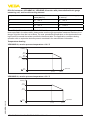
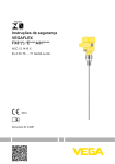
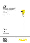
Safety instructions
VEGABAR B8*.IC/U/O/H/T
VEGABAR B8*.VC
Additional current output
IECEx TUN 13.0033 X
Ex ia IIC T6 … T1 Ga, Ga/Gb, Gb
0044
Document ID: 48818
Contents
1 Area of applicability.................................................................................................................. 3
2 General information.................................................................................................................. 3
3 Technical data........................................................................................................................... 4
4 Application conditions............................................................................................................. 5
5 Protection against static electricity........................................................................................ 8
6 Use of an overvoltage arrester................................................................................................ 8
7Grounding.................................................................................................................................. 8
8 Impact and friction sparks....................................................................................................... 9
9 Material resistance................................................................................................................... 9
10 Mounting with external indicating unit VEGADIS 61/81........................................................ 9
11Installation/mounting............................................................................................................... 9
12 Installation of the with separate housing.............................................................................. 9
Please note:
These safety instructions are part of the documentation:
•
•
•
•
•
2
VEGABAR 82
–– 45027 - 4 … 20 mA, 45028 - 4 … 20 mA/HART, 45031 - Profibus PA, 45032 - Foundation
Fieldbus
VEGABAR 83
–– 45033 - 4 … 20 mA, 45034 - 4 … 20 mA/HART, 45037 - Profibus PA, 45038 - Foundation
Fieldbus
VEGABAR 86
–– 45506 - 4 … 20 mA, 45039 - 4 … 20 mA/HART, 45042 - Profibus PA, 45043 - Foundation
Fieldbus
VEGABAR 87
–– 45507 - 4 … 20 mA, 45044 - 4 … 20 mA/HART, 45047 - Profibus PA, 45048 - Foundation
Fieldbus
48819 - Certificate of Conformity IECEx TUN 13.0033 X
VEGABAR B8*.IC/U/O/H/T VEGABAR B8*.VC Additional current output
48818-EN-141111
•
VEGABAR 81
–– 45025 - 4 … 20 mA, 45018 - 4 … 20 mA/HART, 45020 - Profibus PA, 45021 - Foundation
Fieldbus
1
Area of applicability
2
General information
These safety instructions apply to the pressuer transmitters VEGABAR B81/82/83/86/87.IC/U/
O/H/T and VEGABAR B81/82/83/86/87.VC with integrated electronics H (4 … 20 mA/HART), A
(4 … 20 mA/HART with SIL qualification) witht supplementary electronics (Z) according to Certificate of Conformity IECEx TUN 13.0033 X issue No. 1 (certificate number on the type label) and for
all instruments with the number of the safety instruction (48818) on the type label.
The pressure-based measuring instruments VEGABAR B8*.IC/U/O/H/T, VEGABAR B8*.VC are
also used for pressure and level measurement in hazardous areas.
The measured products can also be combustible liquids, gases, mist or vapour.
The VEGABAR B8*.IC/U/O/H/T, VEGABAR B8*.VC consist of an electronics housing with integrated
electronics module, a process connection element and a sensor, the pressure measuring cell with
optionally connected chemical seal. As an option, the display and adjustment module can also be
mounted.
The VEGABAR B8*.IC/U/O/H/T, VEGABAR B8*.VC are suitable for use in hazardous atmospheres
of all combustible materials of explosion group IIA, IIB and IIC for applications requiring instruments
of EPL-Ga, EPL-Ga/Gb or EPL-Gb.
If the VEGABAR B8*.IC/U/O/H/T, VEGABAR B8*.VC are installed and operated in hazardous areas,
the general Ex installation regulations IEC 60079-14 as well as these safety instructions must be
observed.
The operating instructions as well as the installation regulations and standards that apply for explosion protection of electrical systems must always be observed.
The installation of explosion-endangered systems must always be carried out by qualified personnel.
EPL-Ga instrument
The VEGABAR B8*.IC/U/O/H/T, VEGABAR B8*.VC are installed in hazardous areas requiring EPLGa instruments.
EPL-Ga/Gb instrument
The process connection element is installed in the separating wall, which separates areas in which
EPL-Ga or EPL-Gb instruments are required. The electronics housing is installed in hazardous
areas, requiring EPL-Gb instruments. The sensor is installed in hazardous areas requiring EPL-Ga
instruments.
48818-EN-141111
EPL-Gb instrument
The VEGABAR B8*.IC/U/O/H/T, VEGABAR B8*.VC are installed in hazardous areas requiring EPLGb instruments.
VEGABAR B8*.IC/U/O/H/T VEGABAR B8*.VC Additional current output
3
3
Technical data
VEGABAR B8*.IC/U/O/H/T, VEGABAR B8*.VC with integrated electronics H (4 … 20 mA/
HART) or A (4 … 20 mA/HART with SIL qualification) and with supplementary electronics
(Z)
Supply and signal circuit I: (terminals
In ignition protection type intrinsic safety Ex ia IIC/IIB
1[+], 2[-] in the "Ex-i" terminal compart- Only for connection to a certified, intrinsically safe circuit.
ment or plug connection)
Maximum values:
•
•
•
Ui = 30 V
Ii = 131 mA
Pi = 983 mW
The effective internal capacitance Ci is negligibly small.
In the version with permanently mounted connection cable, Ci wire/wire = 150 pF/m and Ci wire/screen = 270 pF/m must
be taken into account.
Power supply and signal circuit II:
(terminal 7[+], 8[-] in the "Ex-i" terminal
compartment)
The effective inner inductance Li is Li ≤ 5 µH. In the version with permanently mounted connection cable, Li =
0.62 µH/m must also be taken into account.
In ignition protection type intrinsic safety Ex ia IIC/IIB
Only for connection to a certified, intrinsically safe circuit.
Maximum values:
•
•
•
Ui = 30 V
Ii = 131 mA
Pi = 983 mW
The effective internal capacitance Ci is negligibly small.
In the version with permanently mounted connection cable, Ci wire/wire = 150 pF/m and Ci wire/screen = 270 pF/m must
be taken into account.
The effective inner inductance Li is Li ≤ 5 µH. In the version with permanently mounted connection cable, Li =
0.62 µH/m must also be taken into account.
48818-EN-141111
4
VEGABAR B8*.IC/U/O/H/T VEGABAR B8*.VC Additional current output
Display and adjustment circuit: (plug con- In ignition protection type intrinsic safety Ex ia IIC
nection of the double chamber housing) For connection to the intrinsically safe circuit of the associated external indicating instrument VEGADIS 61/81
(IECEx PTB 06.0048 X).
The rules for the interconnection of intrinsically safe
circuits between VEGABAR B8*.IC/U/O/H/T, VEGABAR
B8*.VC and the external indicating unit VEGADIS 61/81
are fulfilled, provided that the total inductance and total
capacitance of the connection cable between VEGABAR
B8*.IC/U/O/H/T, VEGABAR B8*.VC and the external
indicating unit VEGADIS 61/81 Lcable = 330 µH and Ccable
= 1.98 µF are not exceeded.
When using the delivered VEGA connection cable
between VEGABAR B8*.IC/U/O/H/T, VEGABAR B8*.
VC and the external indicating unit VEGADIS 61/81, the
following listed cable inductances Li and cable capacitances Ci must be taken into account.
Circuit for the display and adjustment
module: (spring contacts in the "Ex-i"
electronics compartment)
•
•
•
Li = 0.62 µH/m
Ci wire/wire = 150 pF/m
Ci wire/screen = 270 pF/m
In ignition protection type intrinsic safety Ex ia IIC
For connection to the display and adjustment module
PLICSCOM or VEGACONNECT.
VEGABAR B8*.IC/U/O/H/T, VEGABAR B8*.VC Version with separate cable outlet (all electronics)
Circuit between sensor unit and external In ignition protection type intrinsic safety Ex ia IIC
electronics (terminal 1- yellow, terminal With VEGABAR B8*.IC in the version with fix mounted
2 - white, terminal 3 - red, terminal 4 cable on the sensor unit and external electronics, the
black)
supplied cable between the external housing and the
sensor unit must not exceed a length of 180 m.
The intrinsically safe circuits for external connections are electrically separated from parts which
can be grounded.
The intrinsically safe circuits to the sensor are galvanically connected to ground potential.
The metallic parts of VEGABAR B8*.IC/U/O/H/T, VEGABAR B8*.VC are electrically connected with
the earth terminals.
For applications requiring equipment of type EPL-Ga or EPL-Ga/Gb, the intrinsically safe power
supply and signal circuit must correspond to protection class ia.
48818-EN-141111
For applications requiring EPL-Ga resp. EPL-Ga/Gb instruments the VEGABAR B8*.IC/U/O/H/T,
VEGABAR B8*.VC is preferably connected to appropriate instruments with electrically isolated,
intrinsically safe circuits.
4
Application conditions
VEGABAR B8*.IC/U/O/H/T, VEGABAR B8*.VC with integrated electronics Z (4 … 20 mA), H
(4 … 20 mA/HART) or A (4 … 20 mA/HART with SIL qualification), S, T (electronic differential pressure measurement), P (Profibus PA), F (Foundation Fieldbus)
The max. permissible ambient temperatures depending on the temperature classes are specified in
VEGABAR B8*.IC/U/O/H/T VEGABAR B8*.VC Additional current output
5
the following tables.
EPL-Ga instrument
Temperature class
Ambient temperature on the sensor and electronics
T6
-20 … +23 °C
T5, T4, T3, T2, T1
-20 … +60 °C
For applications requiring instruments of EPL-Ga the process pressure of the media must be
between 0.8 … 1.1 bar. The application conditions when operating in the absence of explosive
mixtures can be found in the manufacturer information.
EPL-Ga/Gb instrument
Temperature class
Ambient temperature on the elec- Product temperature on the sentronics
sor
T6
-50 … +39 °C
-20 … +23 °C
T5, T4, T3, T2, T1
-50 … +70 °C
-20 … +60 °C
For applications requiring EPL-Ga/Gb instruments the process pressure of the media must be
between 0.8 … 1.1 bar. If the VEGABAR B8*.IC/U/O/H/T, VEGABAR B8*.VC are operated at
temperatures higher than those specified in the above table, please make sure through appropriate measures that there is no danger of ignition from the hot surfaces. The maximum temperature
on the electronics/housing should not exceed the values specified in the above table. The application conditions during operation in areas with no explosive mixtures are stated in the manufacturer
information.
EPL-Gb instrument, VEGABAR 82, VEGABAR 83 with METEC measuring cell
Temperature class
Ambient temperature on the elec- Product temperature range (sentronics (Zone 1)
sor, zone 1)
T6
-50 … +39 °C
-50 … +39 °C
T5
-50 … +70 °C
-50 … +100 °C
T4
-50 … +50 °C
-50 … +135 °C
T3, T2, T1
-50 … +50 °C
-50 … +200 °C
EPL-Gb instrument, VEGABAR 83 version with piezoresistive/strain gauge measuring cell,
version without cooling element
Ambient temperature on the elec- Product temperature range (sentronics (Zone 1)
sor, zone 1)
T6
-50 … +39 °C
-50 … +39 °C
T5
-50 … +70 °C
-50 … +85 °C
T4
-50 … +40 °C
-50 … +105 °C
T4, T3, T2, T1
-50 … +30 °C
-50 … +120 °C
6
VEGABAR B8*.IC/U/O/H/T VEGABAR B8*.VC Additional current output
48818-EN-141111
Temperature class
EPL-Gb instrument, VEGABAR 81, VEGABAR 83 version with piezoresistive/strain gauge
measuring cell, version with cooling element
Temperature class
Ambient temperature on the elec- Product temperature range (sentronics (Zone 1)
sor, zone 1)
T6
-50 … +39 °C
-50 … +39 °C
T5
-50 … +70 °C
-50 … +85 °C
T4
-50 … +50 °C
-50 … +120 °C
T3, T2, T1
-50 … +40 °C
-50 … +150 °C
If the VEGABAR B8*.IC/U/O/H/T, VEGABAR B8*.VC are operated at temperatures higher than
those specified in the above table, please make sure through appropriate measures that there is no
danger of ignition from the hot surfaces. The max. permissible temperature on the electronics/housing should not exceed the values specified in the above table. The application conditions during
operation with no explosive mixtures present are stated in the manufacturer information.
Temperature derating
VEGABAR 82, version process temperature +130 °C
Tambient
housing
70°C
(158°F)
60°C
(140°F)
55°C
(131°F) 50°C
(122°F)
0°C
(32°F)
100°C
(212°F)
130°C
(266°F)
Tprocess
VEGABAR 82, version process temperature +150 °C
Tambient
housing
70°C
(158°F)
48818-EN-141111
50°C
(122°F)
0°C
(32°F)
100°C
(212°F)
150°C
(302°F)
VEGABAR B8*.IC/U/O/H/T VEGABAR B8*.VC Additional current output
Tprocess
7
VEGABAR 81, VEGABAR 83
Tambient
housing
70°C
(158°F)
65°C
(149°F) 60°C
(140°F)
55°C
(131°F)
0°C
(32°F)
1
2
3
4
5
4
80°C
(176°F)
5
105°C
(221°F)
110°C
(239°F)
1
150°C 160°C
(302°F) (320°F)
2
3
180°C
(356°F)
200°C
(392°F)
Tprocess
Version: METEC measuring cell, process temperature max. 150 °C
Version: METEC measuring cell, process temperature max. 180 °C
Version: METEC measuring cell, process temperature max. 200 °C
Version: Piezoresistive/strain gauge measuring cell, without cooling element
Version: Piezoresistive/strain gauge measuring cell, with cooling element
The temperature ranges for operation specified in the operating instruction must not be exceeded.
5
Protection against static electricity
The VEGABAR B8*.IC/U/O/H/T, VEGABAR B8*.VC in versions with electrostatically chargeable
plastic parts, such as e.g. plastic housing, metal housing with inspection window, with plastic
coated sensors, suspension cable or suspension hose, distance tube or connection cable with the
separated version, a caution label points out the safety measures that must be taken with regard to
electrostatic charges during operation.
Caution: Plastic parts! Danger of electrostatic charging!
•
•
•
6
Avoid friction
No dry cleaning
Do not mount in areas with flowing, non-conductive products
Use of an overvoltage arrester
If necessary, a suitable overvoltage arrester can be connected in front of the VEGABAR B8*.
IC/U/O/H/T, VEGABAR B8*.VC.
7Grounding
In order to avoid the danger of electrostatic charging of the metallic parts, the VEGABAR B8*.
IC/U/O/H/T, VEGABAR B8*.VC must be electrostatically connected to the local potential equalisation (transfer resistance ≤ 1 MΩ), e.g. via the ground terminal, when used as EPL-Ga instrument or
8
VEGABAR B8*.IC/U/O/H/T VEGABAR B8*.VC Additional current output
48818-EN-141111
When used as EPL-Ga or EPL-Ga/Gb instrument, as far as necessary analogue, a suitable
overvoltage arrester must be connected in front as protection against voltage surges according to
IEC 60079-14 chapter 12.3.
EPL-Ga/Gb instrument.
8
Impact and friction sparks
9
Material resistance
10
Mounting with external indicating unit VEGADIS 61/81
When used as EPL-Ga or EPL-Ga/Gb instruments, the VEGABAR B8*.IC/U/O/H/T, VEGABAR B8*.
VC in aluminium/titanium versions must be mounted in such a way that sparks from impact and friction between aluminium/titanium and steel (except stainless steel, if the presence of rust particles
can be excluded) cannot occur.
For applications requiring instruments of type EPL-Ga or EPL-Ga/Gb the VEGABAR B8*.IC/U/
O/H/T, VEGABAR B8*.VC must only be used in products against which the wetted materials are
sufficiently resistant.
The intrinsically safe signal circuit between VEGABAR B8*.IC/U/O/H/T, VEGABAR B8*.VC and the
external indicating unit VEGADIS 61/81 should be set up without grounding. The required insulation voltage is > 500 V AC. When using the VEGA connection cable included with the delivery, this
requirement is fulfilled. If grounding of the cable screen is required, it must be carried out according
to IEC 60079-14 paragr. 12.2.2.3.
11Installation/mounting
The VEGABAR B8*.IC/U/O/H/T, VEGABAR B8*.VC have to be mounted such that the sensor is effectively secured against touching the vessel wall, under consideration of other vessel installations
and flow conditions in the vessel. This applies especially to suspension pressure transmitters and
versions with distance tube lengths over 3 m.
12
Installation of the VEGABAR B8*.IC/U/O/H/T, VEGABAR B8*.VC with
separate housing
48818-EN-141111
With the version with separate housing of the pressure transmitter VEGABAR B8*.IC/U/O/H/T, VEGABAR B8*.VC, the potential equalization must be previded in the complete range of the connection cable between electronics housing and transmitter housing.
VEGABAR B8*.IC/U/O/H/T VEGABAR B8*.VC Additional current output
9
Notes
48818-EN-141111
10
VEGABAR B8*.IC/U/O/H/T VEGABAR B8*.VC Additional current output
48818-EN-141111
Notes
VEGABAR B8*.IC/U/O/H/T VEGABAR B8*.VC Additional current output
11
All statements concerning scope of delivery, application, practical use and operating conditions of the sensors and processing systems correspond to the information
available at the time of printing.
Subject to change without prior notice
© VEGA Grieshaber KG, Schiltach/Germany 2014
VEGA Grieshaber KG
Am Hohenstein 113
77761 Schiltach
Germany
Phone +49 7836 50-0
Fax +49 7836 50-201
E-mail: [email protected]
www.vega.com
48818-EN-141111
Printing date: